EP1498880A2 - Objective lens driving apparatus - Google Patents
Objective lens driving apparatus Download PDFInfo
- Publication number
- EP1498880A2 EP1498880A2 EP04251050A EP04251050A EP1498880A2 EP 1498880 A2 EP1498880 A2 EP 1498880A2 EP 04251050 A EP04251050 A EP 04251050A EP 04251050 A EP04251050 A EP 04251050A EP 1498880 A2 EP1498880 A2 EP 1498880A2
- Authority
- EP
- European Patent Office
- Prior art keywords
- lens holder
- objective lens
- center
- magnet
- driving apparatus
- Prior art date
- Legal status (The legal status is an assumption and is not a legal conclusion. Google has not performed a legal analysis and makes no representation as to the accuracy of the status listed.)
- Withdrawn
Links
Images




Classifications
-
- G—PHYSICS
- G11—INFORMATION STORAGE
- G11B—INFORMATION STORAGE BASED ON RELATIVE MOVEMENT BETWEEN RECORD CARRIER AND TRANSDUCER
- G11B7/00—Recording or reproducing by optical means, e.g. recording using a thermal beam of optical radiation by modifying optical properties or the physical structure, reproducing using an optical beam at lower power by sensing optical properties; Record carriers therefor
- G11B7/08—Disposition or mounting of heads or light sources relatively to record carriers
- G11B7/09—Disposition or mounting of heads or light sources relatively to record carriers with provision for moving the light beam or focus plane for the purpose of maintaining alignment of the light beam relative to the record carrier during transducing operation, e.g. to compensate for surface irregularities of the latter or for track following
- G11B7/0925—Electromechanical actuators for lens positioning
- G11B7/0932—Details of sprung supports
-
- G—PHYSICS
- G11—INFORMATION STORAGE
- G11B—INFORMATION STORAGE BASED ON RELATIVE MOVEMENT BETWEEN RECORD CARRIER AND TRANSDUCER
- G11B7/00—Recording or reproducing by optical means, e.g. recording using a thermal beam of optical radiation by modifying optical properties or the physical structure, reproducing using an optical beam at lower power by sensing optical properties; Record carriers therefor
- G11B7/08—Disposition or mounting of heads or light sources relatively to record carriers
- G11B7/09—Disposition or mounting of heads or light sources relatively to record carriers with provision for moving the light beam or focus plane for the purpose of maintaining alignment of the light beam relative to the record carrier during transducing operation, e.g. to compensate for surface irregularities of the latter or for track following
- G11B7/095—Disposition or mounting of heads or light sources relatively to record carriers with provision for moving the light beam or focus plane for the purpose of maintaining alignment of the light beam relative to the record carrier during transducing operation, e.g. to compensate for surface irregularities of the latter or for track following specially adapted for discs, e.g. for compensation of eccentricity or wobble
- G11B7/0956—Disposition or mounting of heads or light sources relatively to record carriers with provision for moving the light beam or focus plane for the purpose of maintaining alignment of the light beam relative to the record carrier during transducing operation, e.g. to compensate for surface irregularities of the latter or for track following specially adapted for discs, e.g. for compensation of eccentricity or wobble to compensate for tilt, skew, warp or inclination of the disc, i.e. maintain the optical axis at right angles to the disc
Definitions
- This invention relates to an objective lens driving apparatus used in an optical pickup for an optical disk drive.
- An optical disk drive is an apparatus for reading information recorded in an optical disk (such as CD, CD-ROM, CD-R, CD-RW, DVD-ROM, DVD+R, DVD-R, DVD-RAM, DVD+RW, and DVD-RW) and writing information into the optical disk.
- the optical disk drive of the type has an optical pickup for irradiating a laser beam onto the optical disk and detecting a reflected beam from the optical disk in order to read information from the optical disk and write information into the optical disk.
- the optical pickup comprises a laser source for emitting the laser beam and an optical system for guiding the laser beam to the optical disk and guiding the reflected beam to an optical detector.
- the optical system contains an objective lens faced to the optical disk.
- the objective lens used in the optical pickup must be accurately controlled in position with respect to a focusing direction along an optical axis and a tracking direction along a radial direction of the optical disk so as to precisely converge or focus the laser beam onto a recording surface (track) of the optical disk which is rotated.
- the objective lens must be controlled in tilt also.
- the objective lens is held and driven by an objective lens driving apparatus.
- the objective lens driving apparatus comprises a lens holder holding the objective lens and a plurality of suspension wires elastically supporting the lens holder so as to enable focusing control, tracking control, and tilting control.
- the lens holder is provided with a focusing coil, a tracking coil, and a tilting coil each of which is wound on or attached to the lens holder.
- Each of these coils is partly located within a gap of a magnetic circuit.
- the objective lens driving apparatus can finely control the position and the tilt of the objective lens by controlling an electric current flowing through each of the coils (for example, see Japanese Patent Application Publication (JP-A) 2001-93177).
- the conventional objective lens driving apparatus comprises an objective lens 11, a lens holder 12, a focusing coil 13, a plurality of tracking coils 14, a plurality of tilting coils 15, a pair of yokes 16, a pair of magnets 17, a plurality of suspension wires 18, and a base 19.
- the objective lens 11 is disposed on an upper surface of the lens holder 12.
- the focusing coil 13 is wound around side surfaces of the lens holder 12.
- the tracking coils 14 and the tilting coils 15 are attached to the side surfaces of the lens holder 12.
- Each of the suspension wires 18, four in number has one end fixed to the lens holder 12 and the other end fixed to the base 19.
- the lens holder 12 is elastically supported to be movable in the focusing direction (up-and-down direction in the figure) and in the tracking direction (forward-and-rearward direction in the figure) and to be tiltable in the radial direction of the optical disk (circumferential direction of a rotation axis extending in the leftward-and-rightward direction in the figure).
- a combination of one of the yokes 16 and one of the magnets 17 forms a magnetic circuit.
- a combination of the other yoke 16 and the other magnet 17 forms another magnetic circuit.
- each of the focusing coil 13, the tracking coils 14, and the tilting coils 15 is partly located.
- the lens holder 12 when each of the focusing coil 13, the tracking coils 14, and the tilting coils 15 is supplied with an appropriate electric current, the lens holder 12 (and the objective lens 11) can be moved and/or tilted in response to the electric current. As a consequence, the laser beam can be properly focused on a track on a recording surface of the optical disk.
- the lens holder is supported by the four suspension wires in a cantilevered fashion. Therefore, when focusing shift by the focusing control and tracking shift by the tracking control simultaneously occur, a force twisting the suspension wires (in the radial direction) is produced. This force makes the lens holder (i.e., the objective lens) be tilted with respect to the optical disk.
- the tilting coil may be used in order to correct such tilting.
- the magnitude of tilting tilt change
- the magnets are disposed so that their centers in a height direction are coincident with the center of driving (neutral position) of the lens holder.
- a two-wavelength optical pickup which is adaptable for both of a CD (Compact Disk) and a DVD (Digital Video or Versatile Disk).
- the position of the objective lens in the focusing direction must be changed between the CD and the DVD as the optical disk.
- an objective lens driving apparatus used in the two-wavelength optical pickup must have two reference positions (reference of driving) for the CD and the DVD. It is assumed here that one of these reference positions is coincident with the center of driving of the lens holder. In this event, the other reference position is widely separated from the center of driving and the displacement caused by the focusing control and the tracking control will be large.
- the center of driving of the lens holder is located between the reference positions for the CD and the DVD. More specifically, the reference position for the CD is nearer to the optical disk than the center of driving while the reference position for the DVD is farther from the optical disk than the center of driving.
- the objective lens driving apparatus used in the two-wavelength optical pickup may sometimes exhibit a tilt change beyond an allowable range if the lens holder is shifted by a predetermined amount.
- the objective lens driving apparatus is disadvantageous in that a margin for the tilt change is small.
- an objective lens driving apparatus comprising a lens holder (22) provided with a plurality of coils (23, 24, 25) and swingably supported by a suspension wire (28), and a magnet (27) for supplying a driving force to the lens holder by an electromagnetic action produced between the magnet and the coils, wherein the center of the magnet (Mc) in a height direction is located above the center of driving (Dc) of the lens holder.
- the center of the magnet in the height direction is located above both of CD and DVD reference positions of the lens holder.
- the center of the magnet in the height direction is located above the center of driving of the lens holder so that a tilt change with respect to a shift of the lens holder can be reduced as compared with the conventional apparatus.
- a margin for the tilt change can be increased so as to reduce a tilt defect rate upon production.
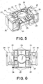
- an objective lens driving apparatus comprises an objective lens 21, a lens holder 22 holding the objective lens 21, a focusing coil 23, a plurality of tracking coils 24, a plurality of tilting coils 25 (Fig. 5), a pair of yokes 26, a pair of magnets 27, a plurality of suspension wires 28, a base 29, and a top cover (not shown).
- the tilting coils 25 are located inside the focusing coil 23.
- the lens holder 22 comprises two members separable in a vertical direction as shown in Fig. 3.
- the tilting coils 25 are respectively wound around four tilting coil bobbins 31 formed on one of the members.
- the focusing coil 23 is wound around a whole of the four tilting coil bobbins 31 each of which is provided with the tilting coil 25 wound therearound.
- a combination of the four tilting coil bobbins 31 serves as a single focusing coil bobbin.
- the base 29 is removed from the objective lens driving apparatus illustrated in Fig. 2.
- the lens holder 22 is fixed to one ends of the four suspension wires 28.
- the other ends of the suspension wires 28 are fixed to the base 29.
- the lens holder 22 is supported in a cantilevered fashion to be swingable with respect to the base 29.
- the focusing coil 23, the tracking coils 24, and the tilting coils 25 are wound.
- the suspension wires 28 are electrically connected to end portions of the focusing coil 23 and the tracking coils 24.
- the tilting coils 25 are electrically connected to lead lines 41 arranged in parallel to the suspension wires 28.
- Each of the yokes 26 has a flat plate portion 261 fixed to the base 29, a bottom plate portion 262 extending from an edge of the flat plate portion 261 to be perpendicular to the flat plate portion 261, and a U-shaped plate portion 263 extending from an edge of the bottom plate portion 262 to be parallel to the flat plate portion 261.
- the U-shaped plate portion 263 has two arms inserted into rectangular holes formed in the lens holder 22.
- the magnet 27 is fixed on a surface of the flat plate portion 261 of the yoke 26 which is faced to the U-shaped plate portion 263.
- the objective lens driving apparatus is mounted to an optical base of an optical disk drive (not shown) to form an optical pickup.
- the optical base is attached to a guide bar to be movable in a radial direction (tracking direction Tr) of an optical disk (71 in Figs. 7 and 8) introduced into the optical disk drive.
- the optical base is provided with a laser diode, an optical detector, and a predetermined optical system. A laser beam from a laser diode is irradiated through the objective lens 21 to the optical disk and a reflected beam reflected from the optical disk is directed to the optical detector.
- the lens holder 22 is tilted in the tracking direction (Tr) (rotated around a rotation axis parallel to a tangential direction Tg), moved in the tracking direction (Tr), or moved in a focusing direction (F) in accordance with the relationship between each coil and magnetic fields produced by the yokes 26 and the magnets 27.
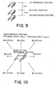
- the lens holder 22 is in a neutral position when all of the coils 23, 24, and 25 are supplied with no electric current.
- the lens holder 22 and the magnets 27 are arranged so that the center of the lens holder 22 in the tracking direction (up-and-down direction in the figure) is coincident with the centers of the magnets 27 in the tracking direction. At this time, end faces of the magnets 27 in the tracking direction are coincident with the centers of the tracking coils 24 in the tracking direction, respectively.
- the lens holder 22 and the magnets 27 are arranged so that the center of the magnet Mc in a height direction (focusing direction) is located at an upper position (near to the optical disk 71) higher than the center of driving Dc of the lens holder 22 by a distance H (for example, 0.6mm in case where each magnet has a height of 4.2mm and a thickness of 2.1mm). If the objective lens 21 is located at a position same as that of the conventional apparatus, the magnet 27 is located nearer to the optical disk 71 than in the conventional apparatus.
- Fig. 9 measurement was carried out in the following manner. With reference to the neutral position (center of driving) of the lens holder as a reference, the CD reference position and the DVD reference position were determined. From each of the reference positions, the lens holder 22 was shifted as shown in Fig. 10. Then, the tilt was measured by an autocollimator. The result is shown in Fig. 11.
- a range 111 is a tilt allowance range in case where the optical disk is a DVD.
- a range 112 is a tilt allowance range in case where the optical disk is a CD.
- the tilt is greater as the focusing shift is greater in case where the focusing shift has a positive value.
- the tilt is smaller as the focusing shift is greater in case where the focusing shift has a negative value.
- the tilt change is not symmetrical between upward displacement and downward displacement the lens holder 22 from the neutral position. Presumably, this is because the yokes 26 are not present above the magnets 27 and the coils 23, 24, and 25.
- a margin for the tilt change is increased if the CD reference position and the DVD reference position are lowered. Therefore, in this embodiment, the magnets 27 are located at a higher position so as to achieve the effect equivalent to that obtained by lowering the CD reference position and the DVD reference position.
- the distance H must be equal to or greater than 0.5mm.
- the position of the magnet 27 is excessively high, the tilt is gradually increased as the focusing shift is greater even if the focusing shift has a negative value. Therefore, in order that the defect rate due to production variation is substantially equal to zero, the distance H must be equal to or smaller than 0.7mm.
- the center of the magnet in the height direction is 0.6mm higher than that of the center of driving of the lens holder 22. Furthermore, the center of driving (neutral position) of the lens holder 22 is used as the DVD reference position. The CD reference position is 0.36mm higher than the DVD reference position and is located below the center of the magnet in the height direction.
Landscapes
- Optical Recording Or Reproduction (AREA)
Abstract
Description
Claims (4)
- An objective lens driving apparatus comprising a lens holder provided with a plurality of coils and swingably supported by a suspension wire, and a magnet for supplying a driving force to said lens holder by an electromagnetic action produced between said magnet and said coils, wherein the center of said magnet in a height direction is located above the center of driving of said lens holder.
- An objective lens driving apparatus as claimed in claim 1, wherein:the center of said magnet in the height direction is located above both of CD and DVD reference positions of said lens holder.
- An objective lens driving apparatus as claimed in claim 2, wherein:said DVD reference position is coincident with the center of driving of said lens holder.
- An objective lens driving apparatus as claimed in claim 1, wherein:the distance between the center of said magnet in the height direction and the center of driving of said lens holder falls within a range between 0.5mm and 0.7mm.
Applications Claiming Priority (2)
| Application Number | Priority Date | Filing Date | Title |
|---|---|---|---|
| JP2003275821 | 2003-07-17 | ||
| JP2003275821A JP2005038537A (en) | 2003-07-17 | 2003-07-17 | Objective lens drive |
Publications (2)
| Publication Number | Publication Date |
|---|---|
| EP1498880A2 true EP1498880A2 (en) | 2005-01-19 |
| EP1498880A3 EP1498880A3 (en) | 2005-11-02 |
Family
ID=33475566
Family Applications (1)
| Application Number | Title | Priority Date | Filing Date |
|---|---|---|---|
| EP04251050A Withdrawn EP1498880A3 (en) | 2003-07-17 | 2004-02-26 | Objective lens driving apparatus |
Country Status (4)
| Country | Link |
|---|---|
| US (1) | US7319564B2 (en) |
| EP (1) | EP1498880A3 (en) |
| JP (1) | JP2005038537A (en) |
| KR (1) | KR20050010467A (en) |
Families Citing this family (6)
| Publication number | Priority date | Publication date | Assignee | Title |
|---|---|---|---|---|
| WO2005096288A1 (en) * | 2004-03-30 | 2005-10-13 | Pioneer Corporation | Actuator for pickup, pickup device, recording medium drive device, and method of producing actuator for pickup |
| JP2006066016A (en) * | 2004-08-30 | 2006-03-09 | Mitsumi Electric Co Ltd | Objective lens drive |
| KR100689035B1 (en) * | 2005-04-14 | 2007-03-08 | 삼성전자주식회사 | Actuators and optical recording and / or reproducing apparatus for optical pickup |
| JP4693510B2 (en) * | 2005-06-08 | 2011-06-01 | 三洋電機株式会社 | Objective lens drive |
| JP2008090920A (en) * | 2006-10-02 | 2008-04-17 | Mitsumi Electric Co Ltd | Optical pickup actuator |
| JP2008122594A (en) * | 2006-11-10 | 2008-05-29 | Konica Minolta Opto Inc | Lens driving device |
Family Cites Families (7)
| Publication number | Priority date | Publication date | Assignee | Title |
|---|---|---|---|---|
| US463501A (en) * | 1891-11-17 | Steam-generator | ||
| JPH05258325A (en) * | 1992-01-13 | 1993-10-08 | Sharp Corp | Objective lens driving device |
| JP3658526B2 (en) | 1999-09-22 | 2005-06-08 | 株式会社日立メディアエレクトロニクス | Objective lens driving device and optical disk device using the same |
| JP3890941B2 (en) * | 2001-10-02 | 2007-03-07 | 日本電気株式会社 | Objective lens drive |
| JP2003331443A (en) * | 2002-05-10 | 2003-11-21 | Toshiba Corp | Objective lens driving device and optical head having the same |
| KR100878525B1 (en) * | 2002-05-24 | 2009-01-13 | 삼성전자주식회사 | Optical Pickup Actuator |
| JP2004185789A (en) * | 2002-10-08 | 2004-07-02 | Ricoh Co Ltd | Lens actuator, optical pickup device and optical disk device |
-
2003
- 2003-07-17 JP JP2003275821A patent/JP2005038537A/en not_active Withdrawn
-
2004
- 2004-01-14 KR KR1020040002502A patent/KR20050010467A/en not_active Withdrawn
- 2004-02-26 EP EP04251050A patent/EP1498880A3/en not_active Withdrawn
- 2004-02-26 US US10/789,499 patent/US7319564B2/en not_active Expired - Fee Related
Also Published As
| Publication number | Publication date |
|---|---|
| EP1498880A3 (en) | 2005-11-02 |
| JP2005038537A (en) | 2005-02-10 |
| KR20050010467A (en) | 2005-01-27 |
| US20050013211A1 (en) | 2005-01-20 |
| US7319564B2 (en) | 2008-01-15 |
Similar Documents
| Publication | Publication Date | Title |
|---|---|---|
| US7835253B2 (en) | Actuator having a plurality of objective lenses installed in a lens holder used with an optical pickup | |
| US7319564B2 (en) | Objective lens driving apparatus | |
| US7305688B2 (en) | Tilting movement optical pickup actuator and optical recording and/or reproducing apparatus using the same and method | |
| US20040148620A1 (en) | Magnetic circuit, and optical pickup actuator and optical recording and/or reproducing apparatus using the magnetic circuit | |
| US7458086B2 (en) | Actuator used with an optical pickup | |
| US7543312B2 (en) | Optical pickup device | |
| KR20050050525A (en) | Objective lens driving device | |
| KR20060047382A (en) | Objective lens drive | |
| KR100689042B1 (en) | Actuators and optical recording and / or reproducing apparatus for optical pickup | |
| US7643386B2 (en) | Optical pickup actuator and optical recording and/or reproducing apparatus | |
| KR100689035B1 (en) | Actuators and optical recording and / or reproducing apparatus for optical pickup | |
| JP4088777B2 (en) | Objective lens holder and objective lens driving device | |
| US7310289B2 (en) | Actuator for optical pickup of an optical disk drive and a method of using the same | |
| CN1333395C (en) | Objective lens driving apparatus and optical disc apparatus | |
| US7558010B2 (en) | Optical pick-up actuator and optical recording and/or reproducing apparatus including the optical pick-up actuator | |
| KR100629487B1 (en) | Actuator and optical recording / reproducing device for optical pickup | |
| KR100677746B1 (en) | Optical pickup device of optical recording / playback device | |
| CN101123099A (en) | optical pickup | |
| JP2005174475A (en) | Objective lens drive | |
| JP2009070440A (en) | Optical pickup device | |
| JPH09305995A (en) | Objective lens drive | |
| KR20050096458A (en) | Symmetric actuator for optical pick-up | |
| KR20010056081A (en) | Actuator for compensating inclination of axis of beam in optical pick up |
Legal Events
| Date | Code | Title | Description |
|---|---|---|---|
| PUAI | Public reference made under article 153(3) epc to a published international application that has entered the european phase |
Free format text: ORIGINAL CODE: 0009012 |
|
| AK | Designated contracting states |
Kind code of ref document: A2 Designated state(s): AT BE BG CH CY CZ DE DK EE ES FI FR GB GR HU IE IT LI LU MC NL PT RO SE SI SK TR |
|
| AX | Request for extension of the european patent |
Extension state: AL HR LT LV MK |
|
| PUAL | Search report despatched |
Free format text: ORIGINAL CODE: 0009013 |
|
| AK | Designated contracting states |
Kind code of ref document: A3 Designated state(s): AT BE BG CH CY CZ DE DK EE ES FI FR GB GR HU IE IT LI LU MC NL PT RO SE SI SK TR |
|
| AX | Request for extension of the european patent |
Extension state: AL LT LV MK |
|
| 17P | Request for examination filed |
Effective date: 20060428 |
|
| AKX | Designation fees paid |
Designated state(s): DE NL |
|
| GRAP | Despatch of communication of intention to grant a patent |
Free format text: ORIGINAL CODE: EPIDOSNIGR1 |
|
| STAA | Information on the status of an ep patent application or granted ep patent |
Free format text: STATUS: THE APPLICATION IS DEEMED TO BE WITHDRAWN |
|
| 18D | Application deemed to be withdrawn |
Effective date: 20080901 |