EP1498743A2 - System for displaying residual capacity of a battery and camera - Google Patents
System for displaying residual capacity of a battery and camera Download PDFInfo
- Publication number
- EP1498743A2 EP1498743A2 EP04254234A EP04254234A EP1498743A2 EP 1498743 A2 EP1498743 A2 EP 1498743A2 EP 04254234 A EP04254234 A EP 04254234A EP 04254234 A EP04254234 A EP 04254234A EP 1498743 A2 EP1498743 A2 EP 1498743A2
- Authority
- EP
- European Patent Office
- Prior art keywords
- battery
- remaining capacity
- unit
- information related
- capacity
- Prior art date
- Legal status (The legal status is an assumption and is not a legal conclusion. Google has not performed a legal analysis and makes no representation as to the accuracy of the status listed.)
- Withdrawn
Links
Images




Classifications
-
- G—PHYSICS
- G01—MEASURING; TESTING
- G01R—MEASURING ELECTRIC VARIABLES; MEASURING MAGNETIC VARIABLES
- G01R31/00—Arrangements for testing electric properties; Arrangements for locating electric faults; Arrangements for electrical testing characterised by what is being tested not provided for elsewhere
- G01R31/36—Arrangements for testing, measuring or monitoring the electrical condition of accumulators or electric batteries, e.g. capacity or state of charge [SoC]
- G01R31/3644—Constructional arrangements
- G01R31/3646—Constructional arrangements for indicating electrical conditions or variables, e.g. visual or audible indicators
-
- G—PHYSICS
- G01—MEASURING; TESTING
- G01R—MEASURING ELECTRIC VARIABLES; MEASURING MAGNETIC VARIABLES
- G01R31/00—Arrangements for testing electric properties; Arrangements for locating electric faults; Arrangements for electrical testing characterised by what is being tested not provided for elsewhere
- G01R31/36—Arrangements for testing, measuring or monitoring the electrical condition of accumulators or electric batteries, e.g. capacity or state of charge [SoC]
- G01R31/3644—Constructional arrangements
- G01R31/3648—Constructional arrangements comprising digital calculation means, e.g. for performing an algorithm
-
- G—PHYSICS
- G01—MEASURING; TESTING
- G01R—MEASURING ELECTRIC VARIABLES; MEASURING MAGNETIC VARIABLES
- G01R31/00—Arrangements for testing electric properties; Arrangements for locating electric faults; Arrangements for electrical testing characterised by what is being tested not provided for elsewhere
- G01R31/36—Arrangements for testing, measuring or monitoring the electrical condition of accumulators or electric batteries, e.g. capacity or state of charge [SoC]
- G01R31/382—Arrangements for monitoring battery or accumulator variables, e.g. SoC
Definitions
- the present invention relates to a battery capacity display device for an electronic apparatus driven on battery power and a camera.
- the extent to which the battery has become depleted is checked by detecting the battery voltage (see Japanese Laid Open Patent Publication No. H 9-236852).
- the battery power available in the electronic apparatus needs to be checked by detecting of the battery voltage while a predetermined load current is flowing from the battery.
- Japanese Laid Open Patent Publication No. H 11-355700 requires two power supply systems, i.e., the main source and the backup source, in order to hold the data in the recording buffer.
- a battery capacity display device for an electronic apparatus, comprises: a nonvolatile storage unit that stores information related to a remaining capacity in a rechargeable battery output from a battery module having the rechargeable battery and an arithmetic operation unit that calculates the information related to the remaining capacity in the rechargeable battery based upon a value of an electrical current flowing to the rechargeable battery; a display unit that displays the remaining capacity in the rechargeable battery based upon the information related to the remaining capacity; and a display control unit that controls the display unit so as to display the remaining capacity based upon the information related to the remaining capacity stored at the storage unit at least until the information related to the remaining capacity is output from the battery module following a startup of the electronic apparatus.
- the information related to the remaining capacity includes the remaining capacity itself or a discharged capacity in the rechargeable battery.
- the battery module outputs the latest information related to the remaining capacity over a predetermined time interval; and the display unit displays the remaining capacity in the rechargeable battery based upon the latest information related to the remaining capacity.
- the startup includes a startup effected in an operation OFF state and a startup effected in a power saving operation state.
- the display control unit controls the display unit so as to display the remaining capacity in the rechargeable battery based upon the information related to the remaining capacity stored at the storage unit before entering a state prior to the startup of the electronic apparatus.
- the display control unit controls the display unit so as to perform a display different from a display of the remaining capacity when the battery module becomes newly loaded into the electronic apparatus, at least until the information related to the remaining capacity is output from the battery module following the startup of the electronic apparatus.
- the display control unit controls the display unit to perform a display different from a display of the remaining capacity when the electronic apparatus having been operating on a current supplied from an external source is switched to operate on a current supplied from the battery module, a least until the information related to the remaining capacity is output from the battery module following the switch-over.
- a camera comprises: a battery capacity display device for an electronic apparatus according to any one of the 1st-7th aspects; and a photographing unit that allows a new photographing operation at least until the information related to the remaining capacity is output from the battery module following the startup.
- a camera comprises: a battery capacity display device for an electronic apparatus according to any one of the 1st-7th aspects; and a photographing unit that disallows a new photographing operation at least until the information related to the remaining capacity is output from the battery module following the startup.
- an electronic camera comprises: a remaining capacity obtaining unit that obtains information related to a remaining capacity in a battery that drives the electronic camera; a storage unit that stores photographed image data; a transfer / recording unit that transfers and records the image data stored in the storage unit into a recording medium; a power information calculation unit that calculates a power required while the transfer / recording unit is engaged in transfer and recording processing; and a control unit that allows a start of another photographing operation if the remaining capacity in the battery based upon the obtained information related to the remaining capacity in the battery is equal to or greater than a value of the power calculated by the power information calculation unit and disallows the start of another photographing operation if the remaining capacity in the battery is smaller than a value of the calculated power.
- connection unit that connects a battery module having a rechargeable battery and an arithmetic operation unit that calculates information related to a remaining capacity in the rechargeable battery based upon a value indicating a current flowing to the rechargeable battery; and the remaining capacity obtaining unit obtains the information related to the remaining capacity in the battery from the battery module connected to the connection unit.
- the battery module further includes a temperature detection unit that detects a temperature of the rechargeable battery; and the arithmetic operation unit corrects the information related to the remaining capacity in the rechargeable battery calculated thereby in correspondence to the temperature detected by the temperature detection unit.
- the electronic camera in the electronic camera according to any one of the 10th-12th aspects, it is preferred that: there is further provided a data size setting unit that sets at least either a data size of image data to be recorded into the recording medium or whether or not compression processing is to be executed in response to a setting operation; and the power information calculation unit calculates the required power based upon the image data size or whether or not the compression processing is to be executed set by the data size setting unit and a storage capacity of the storage unit.
- an electronic camera comprises: a remaining capacity obtaining unit that obtains information related to a remaining capacity in a battery that drives the electronic camera; a storage unit that stores photographed image data; a transfer / recording unit that transfers and records the image data stored in the storage unit into a recording medium; and a control unit that allows a start of another photographing operation if the remaining capacity in the battery based upon the obtained information related to the remaining capacity in the battery is equal to or greater than a value of a power required while image data corresponding to a single frame are transferred and recorded by the transfer / recording unit and disallows the start of another photographing operation if the remaining capacity in the battery is smaller than the value of the required power.
- connection unit that connects a battery module having a rechargeable battery and an arithmetic operation unit that calculates information related to a remaining capacity in the rechargeable battery based upon a value indicating a current flowing to the rechargeable battery; and the remaining capacity obtaining unit obtains the information related to the remaining capacity in the battery from the battery module connected to the connection unit.
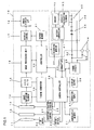
- FIG. 1 is a block diagram of the structure adopted in an electronic still camera 10 achieved in the first embodiment of the present invention.
- a camera controller 26 in FIG. 1 is constituted with a microcomputer and the like. The camera controller 26 executes predetermined arithmetic operations by using signals input thereto from the individual blocks to be detailed later and outputs control signals to the blocks based upon the arithmetic operation results.
- a controller 20 outputs control signals for various blocks in the image-capturing system in response to commands from the camera controller 26.
- An image-capturing element 14 is constituted of a CCD image sensor or the like.
- the image-capturing element 14 captures an image formed with subject light having passed through a photographic lens 11, an aperture 12 and a shutter 13, and outputs an image-capturing signal to a CDS ⁇ A/D conversion circuit 15.
- the CDS ⁇ A/D conversion circuit 15 removes noise from the image-capturing signal through correlated double sampling (CDS) and then converts the analog image-capturing signal to a digital signal.
- CDS correlated double sampling
- the image-capturing elements 14 and the CDS ⁇ A/D conversion circuit 15 are individually driven with predetermined operational timing by drive signals output from a timing generator 19.
- the timing generator 19 starts and stops the output of drive signals in response to commands issued by the controller 20.
- An image processing unit 16 executes specific types of image processing on the digitized signals in response to commands from the controller 20.
- the image processing includes white balance (WB) adjustment processing, compression processing for compressing image data in a predetermined format (eg., JPEG) and decompression processing for decompressing data having undergone the compression processing.
- a display control circuit 17 executes the processing necessary to display an image reproduced by using image data at an image display LCD 18. At the image display LCD 18, the reproduced image is displayed based upon a display control signal output from the display control circuit 17.
- a buffer memory 21 to which image data having undergone the signal processing at the image processing unit 16 are sequentially input, the data are stored on a temporary basis.
- the image data stored in the buffer memory 21 on a temporary basis are recorded into a recording medium 30 constituted of, for instance, a detachable flash memory.
- the buffer memory 21 While the contents recorded in the buffer memory 21 become lost once the power supply stops, the buffer memory 21 has an advantage in that data written into the buffer memory 21 more quickly than into the recording medium 30. In other words, the contents recorded in the recording medium 30 are held even while no power is supplied, but it takes longer to write data into the recording medium 30 than into the buffer memory 21. Accordingly, the controller 20 implements control so as to write image data obtained after starting the photographing sequence into the buffer memory 21 at high speed and, at the same time to transfer and record data stored in the buffer memory 21 into the recording medium 30 at a rate corresponding to the write speed of the recording medium 30.
- Operation signals corresponding to specific operations are output to the camera controller 26 from an operation input member 27 which includes various operating members such as a shutter release button (not shown).
- a display output unit 28 displays the remaining capacity in a battery pack 40 which is to be detailed later, the shutter speed, the aperture value and exposure information in response to a command from the camera controller 26.
- a motor driver 22 implements drive control on an AF motor 23 in response to a command issued by the camera controller 26.
- the AF motor 23 drives a focus lens (not shown) constituting the photographic lens 11 forward/backward along the optical axis.
- An aperture control actuator 24 drives the aperture 12 so as to achieve a specific aperture value in response to a command issued by the camera controller 26.
- a shutter control magnet 25 individually controls the front curtain and the rear curtain (not shown) of the shutter 13 so as to hold/release them independently of each other.
- a power circuit 29 converts a battery voltage supplied from the battery pack 40 or a DC voltage supplied froman external DC source to a voltage needed at the various blocks within the electronic camera 10.
- the power circuit 29 comprises a DC/DC converter.
- the battery pack 40 includes rechargeable (or secondary) battery cells 44, a battery controller 41, a memory 42, a capacity calculation element 43 and a resistor 45.
- the connection unit (interface unit) 35 comprise contacts to which power is supplied and contacts through which signals are transmitted and received, and a structure by which the battery pack 40 can be physically held.
- the battery controller 41 engages in communication with the camera controller 26.
- the battery controller 41 transmits the battery information to the camera controller 26.
- the battery information which indicates the remaining capacity in the rechargeable battery cells 44 is stored in the memory 42.
- the capacity calculation element 43 detects the value of the voltage generated at the two ends of the resistor 45 and ascertains the level of the current (a discharge current in this case) flowing to the rechargeable battery cells 44 by dividing the detected voltage by the resistance value at the resistor 45.
- the capacity calculation element 43 calculates the consumed capacity (consumption amount information) at the rechargeable battery cells 44 through a time integration of the current value, and transmits the results of the calculation to the battery controller 41.
- the consumed capacity may be expressed in units of, for instance, mAH.
- the total capacity of the rechargeable battery cells 44 is stored into the memory 42 when the rechargeable battery cells 44 are charged.
- the battery pack 40 is mounted at a charger (not shown) to be charged.
- the capacity calculation element 43 detects the value of the voltage generated at the two ends of the resistor 45 and ascertains the level of the current (a charge current in this case) flowing to the rechargeable battery cells 44 by dividing the detected voltage by the resistance value at the resistor 45.
- the capacity calculation element 43 calculates the charged capacity at the rechargeable battery cells 44 through a time integration of the current value, and transmits the results of the calculation to the battery controller 41.
- the charged capacity may be expressed in units of mAH.
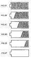
- FIGS. 2A through 2F present examples of the remaining capacity display.
- the display in FIG. 2A indicates that the remaining capacity is 80% to 100%
- the display in FIG. 2B indicates that the remaining capacity is 60% to 80%
- the display in FIG. 2C indicates that the remaining capacity is 40% to 60%
- the display in FIG. 20 indicates that the remaining capacity is 20% to 40%
- the display in FIG. 2E indicates that the remaining capacity is 10% to 20%
- the display in FIG. 2F indicates that the remaining capacity is less than 10%.
- the electronic camera 10 can also be driven on DC power supplied from the outside by connecting an external power input terminal 34 to an external DC source (not shown) such as an AC adapter and applying a DC voltage from the external DC source to the power circuit 29 via a diode 33.
- the level of the voltage originating from the external DC source is set higher than the level of the voltage supplied from the battery pack 40.
- the camera controller 26 assumes that the battery pack 40 is not currently used and accordingly, stops the communication with the battery controller 41 at the battery pack 40.
- the camera controller 26 assumes that the camera is now being driven with the battery pack 40 and starts communicating with the battery controller 41 at the battery pack 40.
- the camera controller 26 starts communication with the battery controller 41 at the battery pack 40 when a signal indicating an ON operation of the main switch at the electronic camera 10 is input and when an operation signal is input from the operation input member 27 during power-saving operation at the electronic camera 10, as well as when the external source detection signal is no longer input.
- the term "power saving operation” refers to an operating mode in which the power consumption is reduced by stopping the camera operations except for the minimum processing that is required such as the operation signal detection when no operation signal has been input from the operation input member 27 over a predetermined length of time. If an operation signal from the operation input member 27 is detected in the power saving operation mode, the camera returns to the normal operating state.
- a nonvolatile memory 31 holds stored contents even after the power supply stops.
- the camera controller 26 stores the battery information it has received from the battery controller 41 into the nonvolatile memory 31 and updates the memory contents each time a new set of battery information is received.
- the present invention is characterized in the remaining capacity display at the display output unit 28 brought up immediately after the camera controller 26 in the electronic camera 10 described above starts communication with the battery controller 41 at the battery pack 40.
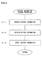
- FIG. 3 presents a flowchart of battery information storage processing executed by the camera controller 26.
- the processing in FIG. 3 is repeatedly executed over a predetermined time interval while the electronic camera 10 is in use and running on power supplied by the battery pack 40 (while the camera controller 26 and the battery controller 41 are in communication with each other).
- step S11 in FIG. 3 the camera controller 26 issues a request for the battery information to the battery controller 41, and then the operation proceeds to step S12.
- step S12 the camera controller 26 receives the battery information from the battery controller 41 before the operation proceeds to step S13.
- step S13 the camera controller 26 stores the received battery information into the nonvolatile memory 31 (updates the memory contents) and then the processing in FIG. 3 ends. Thus, the latest battery information is stored in the nonvolatile memory 31.
- the current consumed in an electronic apparatus fluctuates significantly depending upon the operating state of the electronic apparatus. For instance, when the shutter release button (not shown) is pressed half way down, the AF motor 23 is driven, resulting in an increase in the current in the electronic camera. Then, as a full press operation is performed at the shutter release button, the photographing sequence starts, further increasing the consumption current. As the photographing operation starts, power is supplied to the aperture control actuator 24, the shutter control magnet 25, the image-capturing element 14 and the like, and subsequently, the consumption current fluctuates during the photographing processing sequence until all image data stored in the buffer memory 21 are transferred and written into the recording medium 30.
- the camera controller 26 Since a specific length of time (2 sec in the example explained above) is needed for the battery controller 41 to calculate the remaining capacity in the battery cells 44, the camera controller 26 does not receive battery information immediately after starting communication with the battery controller 41 at the battery pack 40. The camera controller 26 displays the remaining capacity based upon the battery information stored in the nonvolatile memory 31 until new battery information is transmitted from the battery controller 41. During this time, photographing is allowed.
- FIG. 4 presents a flowchart of remaining capacity display processing executed immediately after the communication between the camera controller 26 and the battery controller 41 starts.
- the processing in FIG. 4 is started up in response to an ON operation of the main switch (not shown) at the electronic camera 10 or in response to an operation of the operation input member 27 while the electronic camera 10 is in the power saving operation mode.
- the camera controller 26 performs initial setting to enable photography with the camera.
- the camera controller 26 reads out the battery information stored in the nonvolatile memory 31 and then the operation proceeds to step S22.
- step S22 the camera controller 26 issues an instruction for the display output unit 28 to display the remaining capacity based upon the battery information having been read out, and then the operation proceeds to step S23.
- the remaining capacity which was calculated when the electronic camera 10 was last used is displayed at the display output unit 28.
- step S23 the camera controller 26 makes a decision as to whether or not a preset time period has elapsed. If the preset time period (set greater than the length of time required to calculate the remaining capacity in the battery pack 40 (2 sec in the example) has elapsed since the start of the processing shown in FIG.
- the camera controller 26 makes an affirmative decision in step S23 and the operation proceeds to step S24, whereas the camera controller 26 makes a negative decision in step S23 if the preset time period has not elapsed and the decision-making processing is repeatedly executed.
- the remaining capacity display is sustained by using the past battery information saved in the nonvolatile memory 31.
- step S24 and the camera controller 26 reads out the battery information stored in the nonvolatile memory 31 and the operation proceeds to step S25.
- the battery information has been updated with the battery information newly received from the battery controller 41.
- step S25 the camera controller 26 issues an instruction for the display output unit 28 to display the remaining capacity based upon the battery information having been read out, and then the operation returns to step S24.
- the memory contents in the nonvolatile memory 31 are updated with the most recent battery information through the processing shown in FIG. 3 once it is decided in step S23 that the predetermined time period has elapsed, the remaining capacity can be displayed by using the most recent battery information.
- a photographing start in the electronic camera 10 explained above may be disallowed even when a shutter release operation is performed until the updated remaining capacity is displayed based upon the battery information newly transmitted from the battery controller 41 (step S25).
- the camera controller 26 should determine whether to allow/disallow the photographing start.
- FIG. 9 shows a flowchart of the remaining capacity display processing executed at the camera controller in case of disallowing or inhibiting photography.
- step S200 it is processed to disallow photographing operation with the camera
- strep S201 it is processed to enable photographing operation with the camera. Since other steps are similar to those of above FIG. 4, explanations are omitted.
- the remaining capacity is displayed before the preset time period elapses by using the battery information saved in the nonvolatile memory 31.
- the remaining capacity may be displayed before the preset time period elapses based upon battery information saved in the memory 42 at the battery pack 40.
- the camera controller 26 receives from the battery controller 41 the battery information saved in the memory 42 in step S21, and then the operation proceeds to step S22.
- the battery controller 41 upon receiving the request for battery information from the camera controller 26 before it has calculated the remaining capacity in the battery cells 44, transmits the battery information saved in the memory 42 as an initial value to the camera controller 26. After the remaining capacity in the battery cells 44 is calculated, the battery controller 41 transmits the latest battery information indicating the new value to the camera controller 26.
- a RAM may be utilized in place of the nonvolatile memory 31. Since the battery voltage is applied to the power circuit 29 as long as the battery pack 40 is loaded in the electronic camera, the RAM can be supplied with power via the power circuit 29 even while the main switch (not shown) of the electronic camera is in an OFF state. Thus, the remaining capacity can be displayed based upon the battery information saved in the RAM in a similar manner without using the nonvolatile memory 31.
- the camera controller 26 issues an instruction for the display output unit 28 to assume a display mode different from that for the regular remaining power display, instead of displaying the remaining capacity based upon the battery information saved in the nonvolatile memory 31 before the preset time period elapses.
- the individual display segments in FIG. 2A may, for instance, be made to flash. This prevents a display of the remaining battery power based upon the battery information corresponding to the wrong battery pack 40 and informs the user that the remaining capacity check is in progress. During this time, photographing is disallowed.
- the camera controller 26 issues an instruction for the display output unit 28 to assume a display mode different from that for the regular remaining power display for a predetermined length of time when an input of the external source detection signal stops as well. If the battery pack 40 is replaced while the electronic camera 10 is being driven on a current supplied from the external DC source, the current supply is not interrupted and the camera controller 26 cannot detect that the battery pack 40 is being replaced. Accordingly, a display mode different from that for the regular remaining power display is assumed until new battery information is received from the battery controller 41 of the battery pack 40 after the input of the external source detection signal stops so as to alert the user that the remaining capacity check is in progress. During this time, photographing is disallowed.
- the present invention may also be adopted in a film camera, a portable telephone, a PDA, a personal computer and the like as long as rechargeable batteries are used as a power source.
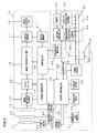
- FIG. 5 is a block diagram of the structure adopted in an electronic still camera 10 achieved in the second embodiment of the present invention. It is only different from FIG. 1 that the battery pack 40 includes a temperature detection element 46. Accordingly, an explanation of the structure adopted in the electronic still camera 10 is referred to the explanation of the first embodiment, and the explanation is omitted.
- the temperature detection element 46 outputs a detection signal obtained by detecting the temperature of the rechargeable battery cells 44 to the battery controller 41.
- the battery capacity needed in the electronic camera 10 to transfer and record image data in the buffer memory 21 into the recording medium 30 is calculated and a further photographing operation is disallowed if the remaining capacity in the battery pack 40 is lower than the calculated battery capacity.
- FIG. 6 presents a flowchart of photographing OK/NG decision-making processing executed in the camera controller 26.
- the camera controller 26 repeatedly executes the processing in FIG. 6 over a predetermined time interval after the main switch (not shown) of the camera 10 is turned on to make a decision as to whether a photographing operation is to be allowed / disallowed. If it is decided that a photographing operation is allowed through the processing shown in FIG. 6, the camera controller 26 starts a photographing sequence in response to a shutter release operation signal input through the operation input member 27. If, on the other hand, it is decided that a photographing operation is disallowed through the processing shown in FIG. 6, the camera controller 26 disallows another execution of the photographing sequence. Thus, even if a shutter release operation signal is input from the operation input member 27, the camera 10 is not engaged in a photographing operation.
- step S111 in FIG. 6 the camera controller 26 calculates the number of frames X of images that can be stored in the buffer memory 21 by using expression (1) below and then the operation proceeds to step S112.
- X (buffer size)/(file size per frame)
- the buffer size in the expression presented above is the storage capacity of the buffer memory 21, which is stored in advance in a ROM area (not shown) inside the camera controller 26. Varying file sizes per frame corresponding to different recording modes are stored in advance in the ROM area (not shown) in the camera controller 26.
- the camera controller 26 reads out the file size corresponding to the current recording mode setting at the camera 10 and uses the file size thus read out for substitution in expression (1).
- the recording modes may include the following.
- step S112 in FIG. 6 the camera controller 26 obtains power information p indicating the amount of power required to write a single image frame by using expression (2) below, before the operation proceeds to step S113.
- p a x t
- a represents the current consumed in the entire camera 10 when writing an image frame into the recording medium 30 (the current supplied from the battery pack 40) and t represents the length of time required to write a single image frame into the recording medium 30.
- the consumed current a changes depending upon whether the recording medium 30 is constituted of a memory or a data storage device.
- the camera controller 26 reads out the current value corresponding to the specific type of recording medium 30 currently loaded in the camera from the ROM area (not shown) inside the camera controller 26 where varying current values are stored in advance.
- the varying lengths of write operation time t are stored in advance in correspondence to the individual recording modes (i.e., the individual file sizes) in the ROM area (not shown) inside the camera controller 26.
- the camera controller 26 reads out the length of time t corresponding to the current recording mode setting at the camera 10 and uses the value thus read out for substitution in expression (2).
- step S113 the camera controller 26 obtains power information P corresponding to X frames through a calculation executed by using expression (3) below, and then the operation proceeds to step S114.
- P X x p
- step S114 the camera controller 26 issues a request for the battery information to the battery controller 41 before the operation proceeds to step S115.
- the camera controller 26 receives the battery information (indicating the remaining capacity) from the battery controller 41 before the operation proceeds to step S116.
- step S116 the camera controller 26 makes a decision as to whether or not (remaining capacity) ⁇ (power information P) is true.
- the camera controller 26 makes an affirmative decision in step S116 if (remaining capacity) ⁇ (power information P) is true to proceed to step S117, whereas it makes a negative decision in step S116 if (remaining capacity) ⁇ (power information P) is true to proceed to step S118.
- step S117 the camera controller 26 judges that the execution of a photographing operation is to be allowed before the processing in FIG. 6 ends.
- step S118 the camera controller 26 judges that the execution of a photographing operation is to be disallowed before the processing in FIG. 6 ends.
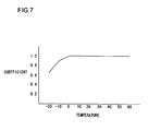
- FIG. 7 is a chart of the temperature compensation coefficient.
- the detected temperature is indicated along the horizontal axis and the temperature compensation coefficient is indicated along the vertical axis.
- FIG. 7 indicates that the coefficient at - 10 °C is 0.9 and that the coefficient at - 20 °C is 0.65, relative to the coefficient of 1 for temperatures equal to or higher than 0°C.
- the relationship between the detected temperature and the temperature compensation coefficient such as that shown in FIG.
- the battery controller 41 reads out the temperature compensation coefficient corresponding to the detected temperature and multiplies the total capacity by the coefficient thus read out for correction. As a result, the substantial remaining capacity at a lower temperature can be ascertained. It is to be noted that the temperature compensation coefficient may be used either as the multiplier with which the remaining capacity is multiplied or the divisor by which the consumed capacity is divided.
- the battery controller 41 transmits information indicating the actual remaining capacity to the camera controller 26 as the battery information.
- a value obtained by subtracting the value of the power information P from the actual remaining capacity may be transmitted to the camera controller 26.
- the camera controller 26 transmits the power information P when requesting the battery information from the battery controller 41 in step S114.
- the battery controller 41 calculates (remaining capacity) - (power information P) and transmits the arithmetic operation results to the camera controller 26 as the battery information.
- the camera controller 26 Upon receiving the battery information, the camera controller 26 makes an affirmative decision in step S116 if (battery information) ⁇ 0 is true to proceed to step S117, but makes a negative decision in step S116 if (battery information) ⁇ 0 is true to proceed to step S118.
- the battery information P may indicate a fixed value.
- power information corresponding to the largest value achievedwith one of the various conceivable combinations of buffer sizes, recording modes and types of recording media 30 is used as the power information P.
- the volume of the arithmetic operation executed at the camera controller 26 is reduced to enable speedier photographing OK/NG decision-making processing.
- FIG. 8 presents a flowchart of the photographing OK/NG decision-making processing executed in the third embodiment of the present invention.
- the camera controller 26 repeatedly executes the processing in FIG. 8 over a predetermined time interval after the main switch (not shown) of the camera 10 is turned on to determine whether the execution of a photographing operation is to be allowed / disallowed.
- the same step numbers are assigned to steps in which processing identical to that in FIG. 6 is executed to preclude the necessity for a repeated explanation thereof.
- step S121 in FIG. 8 the camera controller 26 calculates the number of image frames Y that can be transferred and written into the recording medium 30 with the remaining capacity in the battery pack 40 by using expression (4) below, and then the operation proceeds to step S122.
- Y (remaining capacity)/p p in the expression above represents the power information indicating the power required to write a single image frame which has been calculated in step S112.
- step S122 the camera controller 26 makes a decision as to whether or not Y ⁇ 1 is true.
- the camera controller 26 makes an affirmative decision in step S122 if Y ⁇ 1 is true to proceed to step S117, whereas it makes a negative decision in step S122 if Y ⁇ 1 is true to proceed to step S118.
- step S117 the camera controller 26 determines that the execution of a photographing operation is to be allowed, and then the operation proceeds to step S123.
- step S118 the camera controller 26 determines that the execution of a photographing operation is to be disallowed before the processing in FIG. 8 ends.
- step S123 the camera controller 26 makes a decision as to whether or not Y ⁇ X is true.
- X represents the number of image frames that can be stored in the buffer memory 21.
- the camera controller 26 makes an affirmative decision in step S123 if Y ⁇ X is true and then the processing in FIG. 8 ends. In this situation, the battery pack still have a great deal of remaining capacity and thus, enough power to allow all the data in the buffer memory 21 to be transferred and recorded into the recording medium 30 is assured.
- step S124 the camera controller 26 sets a flag for shortening the call interval for this processing, before ending the processing in FIG. 8.
- the camera controller 26 executes the photographing OK/NG decision-making processing in FIG. 8 at least before starting each photographing sequence.
- the flag is cleared if an affirmative decision is made in step S123.
- the third embodiment explained above makes it possible to prevent any loss of data in the buffer memory 21 due to low battery capacity and to end the data recording into the recording medium 30 before the remaining battery power becomes too low, without having to add another power system as is necessary in the related art.
- the remaining capacity in the battery becomes low (when a negative decision is made in step S123)
- the decision as to whether the execution of a photographing operation is allowed or disallowed can be made for each frame and thus, the remaining capacity in the battery pack 40 can be utilized efficiently until the available power for photographing an image frame is completely depleted.
- the present invention will prove particularly effective in continuous shooting operations executed in an electronic still camera during which a large volume of image data is stored in the buffer memory 21.
- the present invention is not limited to this example.
- the structure of the battery pack 40 may be installed in the camera 10. In this case, only the rechargeable battery cells 44 may be exchangeable. It is also acceptable that the rechargeable battery cells 44 is also installed in the camera and is not exchangeable.
Landscapes
- Physics & Mathematics (AREA)
- General Physics & Mathematics (AREA)
- Studio Devices (AREA)
- Secondary Cells (AREA)
- Tests Of Electric Status Of Batteries (AREA)
- Charge And Discharge Circuits For Batteries Or The Like (AREA)
Abstract
Description
Claims (15)
- A battery capacity display device for an electronic apparatus, comprising:a nonvolatile storage unit that stores information related to a remaining capacity in a rechargeable battery output from a battery module having the rechargeable battery and an arithmetic operation unit that calculates the information related to the remaining capacity in the rechargeable battery based upon a value of an electrical current flowing to the rechargeable battery;a display unit that displays the remaining capacity in the rechargeable battery based upon the information related to the remaining capacity; anda display control unit that controls the display unit so as to display the remaining capacity based upon the information related to the remaining capacity stored at the storage unit at least until the information related to the remaining capacity is output from the batterymodule following a startup of the electronic apparatus.
- A battery capacity display device for an electronic apparatus according to claim 1, wherein:the information related to the remaining capacity includes the remaining capacity itself or a discharged capacity in the rechargeable battery
- A battery capacity display device for an electronic apparatus according to any one of claims 1-2, wherein:the battery module outputs the latest information related to the remaining capacity over a predetermined time interval; andthe display unit displays the remaining capacity in the rechargeable battery based upon the latest information related to the remaining capacity.
- A battery capacity display device for an electronic apparatus according to any one of claims 1-3, wherein:the startup includes a startup effected in an operation OFF state and a startup effected in a power saving operation state.
- A battery capacity display device for an electronic apparatus according to any one of claims 1-4, wherein:the display control unit controls the display unit so as to display the remaining capacity in the rechargeable battery based upon the information related to the remaining capacity stored at the storage unit before entering a state prior to the startup of the electronic apparatus.
- A battery capacity display device for an electronic apparatus according to any one of claims 1-5, wherein:the display control unit controls the display unit so as to perform a display different from a display of the remaining capacity when the battery module becomes newly loaded into the electronic apparatus, at least until the information related to the remaining capacity is output from the battery module following the startup of the electronic apparatus.
- A battery capacity display device for an electronic apparatus according to any one of claims 1-6, wherein:the display control unit controls the display unit to perform a display different from a display of the remaining capacity when the electronic apparatus having been operating on a current supplied from an external source is switched to operate on a current supplied from the battery module, a least until the information related to the remaining capacity is output from the battery module following the switch-over.
- A camera comprising:a battery capacity display device for an electronic apparatus according to any one of claims 1-7; anda photographing unit that allows a new photographing operation at least until the information related to the remaining capacity is output from the battery module following the startup.
- A camera comprising:a battery capacity display device for an electronic apparatus according to any one of claims 1-7; anda photographing unit that disallows a new photographing operation at least until the information related to the remaining capacity is output from the battery module following the startup.
- An electronic camera comprising:a remaining capacity obtaining unit that obtains information related to a remaining capacity in a battery that drives the electronic camera;a storage unit that stores photographed image data;a transfer / recording unit that transfers and records the image data stored in the storage unit into a recording medium;a power information calculation unit that calculates a power required while the transfer / recording unit is engaged in transfer and recording processing; anda control unit that allows a start of another photographing operation if the remaining capacity in the battery based upon the obtained information related to the remaining capacity in the battery is equal to or greater than a value of the power calculated by the power information calculation unit and disallows the start of another photographing operation if the remaining capacity in the battery is smaller than a value of the calculated power.
- An electronic camera according to claim 10, further comprising:a connection unit that connects a battery module having a rechargeable battery and an arithmetic operation unit that calculates information related to a remaining capacity in the rechargeable battery based upon a value indicating a current flowing to the rechargeable battery, wherein:the remaining capacity obtaining unit obtains the information related to the remaining capacity in the battery from the battery module connected to the connection unit.
- An electronic camera according to claim 11, wherein:the battery module further includes a temperature detection unit that detects a temperature of the rechargeable battery; andthe arithmetic operation unit corrects the information related to the remaining capacity in the rechargeable battery calculated thereby in correspondence to the temperature detected by the temperature detection unit.
- An electronic camera according to any one of claims 10-12, further comprising:a data size setting unit that sets at least either a data size of image data to be recorded into the recording medium or whether or not compression processing is to be executed in response to a setting operation, wherein:the power information calculation unit calculates the required power based upon the image data size or whether or not the compression processing is to be executed set by the data size setting unit and a storage capacity of the storage unit.
- An electronic camera comprising:a remaining capacity obtaining unit that obtains information related to a remaining capacity in a battery that drives the electronic camera; a storage unit that stores photographed image data;a transfer / recording unit that transfers and records the image data stored in the storage unit into a recording medium; anda control unit that allows a start of another photographing operation if the remaining capacity in the battery based upon the obtained information related to the remaining capacity in the battery is equal to or greater than a value of a power required while image data corresponding to a single frame are transferred and recorded by the transfer / recording unit and disallows the start of another photographing operation if the remaining capacity in the battery is smaller than the value of the required power.
- An electronic camera according to claim 14, further comprising:a connection unit that connects a battery module having a rechargeable battery and an arithmetic operation unit that calculates information related to a remaining capacity in the rechargeable battery based upon a value indicating a current flowing to the rechargeable battery, wherein:the remaining capacity obtaining unit obtains the information related to the remaining capacity in the battery from the battery module connected to the connection unit.
Applications Claiming Priority (4)
| Application Number | Priority Date | Filing Date | Title |
|---|---|---|---|
| JP2003276643A JP4321168B2 (en) | 2003-07-18 | 2003-07-18 | Battery capacity display device and camera |
| JP2003276644A JP2005039699A (en) | 2003-07-18 | 2003-07-18 | Electronic still camera system |
| JP2003276644 | 2003-07-18 | ||
| JP2003276643 | 2003-07-18 |
Publications (2)
| Publication Number | Publication Date |
|---|---|
| EP1498743A2 true EP1498743A2 (en) | 2005-01-19 |
| EP1498743A3 EP1498743A3 (en) | 2005-05-04 |
Family
ID=33479032
Family Applications (1)
| Application Number | Title | Priority Date | Filing Date |
|---|---|---|---|
| EP04254234A Withdrawn EP1498743A3 (en) | 2003-07-18 | 2004-07-15 | System for displaying residual capacity of a battery and camera |
Country Status (2)
| Country | Link |
|---|---|
| US (1) | US8040430B2 (en) |
| EP (1) | EP1498743A3 (en) |
Cited By (2)
| Publication number | Priority date | Publication date | Assignee | Title |
|---|---|---|---|---|
| WO2006030356A3 (en) * | 2004-09-17 | 2007-05-18 | Koninkl Philips Electronics Nv | Content status provision related to volatile memories |
| WO2009124598A1 (en) * | 2008-04-11 | 2009-10-15 | Jinding Group Co., Ltd | Method, apparatus, and computer program product for use of lcd display in a cordless tool |
Families Citing this family (37)
| Publication number | Priority date | Publication date | Assignee | Title |
|---|---|---|---|---|
| US20060187227A1 (en) * | 2005-01-31 | 2006-08-24 | Jung Edward K | Storage aspects for imaging device |
| US7876357B2 (en) | 2005-01-31 | 2011-01-25 | The Invention Science Fund I, Llc | Estimating shared image device operational capabilities or resources |
| US9910341B2 (en) | 2005-01-31 | 2018-03-06 | The Invention Science Fund I, Llc | Shared image device designation |
| US20060187230A1 (en) * | 2005-01-31 | 2006-08-24 | Searete Llc | Peripheral shared image device sharing |
| US20060173972A1 (en) * | 2005-01-31 | 2006-08-03 | Searete Llc, A Limited Liability Corporation Of The State Of Delaware | Audio sharing |
| US9489717B2 (en) | 2005-01-31 | 2016-11-08 | Invention Science Fund I, Llc | Shared image device |
| US20060190968A1 (en) * | 2005-01-31 | 2006-08-24 | Searete Llc, A Limited Corporation Of The State Of The State Of Delaware | Sharing between shared audio devices |
| US7920169B2 (en) * | 2005-01-31 | 2011-04-05 | Invention Science Fund I, Llc | Proximity of shared image devices |
| US9082456B2 (en) * | 2005-01-31 | 2015-07-14 | The Invention Science Fund I Llc | Shared image device designation |
| US20070236505A1 (en) * | 2005-01-31 | 2007-10-11 | Searete Llc, A Limited Liability Corporation Of The State Of Delaware | Resampling of transformed shared image techniques |
| US20060187228A1 (en) * | 2005-01-31 | 2006-08-24 | Searete Llc, A Limited Liability Corporation Of The State Of Delaware | Sharing including peripheral shared image device |
| US20060171603A1 (en) * | 2005-01-31 | 2006-08-03 | Searete Llc, A Limited Liability Corporation Of The State Of Delaware | Resampling of transformed shared image techniques |
| US8902320B2 (en) * | 2005-01-31 | 2014-12-02 | The Invention Science Fund I, Llc | Shared image device synchronization or designation |
| US8606383B2 (en) * | 2005-01-31 | 2013-12-10 | The Invention Science Fund I, Llc | Audio sharing |
| US20060285150A1 (en) * | 2005-01-31 | 2006-12-21 | Searete Llc, A Limited Liability Corporation Of The State Of Delaware | Regional proximity for shared image device(s) |
| US9124729B2 (en) * | 2005-01-31 | 2015-09-01 | The Invention Science Fund I, Llc | Shared image device synchronization or designation |
| US20060174203A1 (en) * | 2005-01-31 | 2006-08-03 | Searete Llc, A Limited Liability Corporation Of The State Of Delaware | Viewfinder for shared image device |
| US9819490B2 (en) | 2005-05-04 | 2017-11-14 | Invention Science Fund I, Llc | Regional proximity for shared image device(s) |
| US9001215B2 (en) * | 2005-06-02 | 2015-04-07 | The Invention Science Fund I, Llc | Estimating shared image device operational capabilities or resources |
| US10003762B2 (en) | 2005-04-26 | 2018-06-19 | Invention Science Fund I, Llc | Shared image devices |
| JP5161443B2 (en) * | 2006-08-11 | 2013-03-13 | ペンタックスリコーイメージング株式会社 | camera |
| JP5079533B2 (en) * | 2008-01-30 | 2012-11-21 | 京セラ株式会社 | Portable electronic devices |
| WO2010022059A1 (en) | 2008-08-18 | 2010-02-25 | Austin Christopher B | Vehicular battery charger, charging system, and method |
| JP5094655B2 (en) * | 2008-09-12 | 2012-12-12 | キヤノン株式会社 | Imaging device |
| CN102159961B (en) * | 2008-09-22 | 2013-12-25 | 日本胜利株式会社 | Electronic device, method for displaying remaining battery level, and method for displaying operational time |
| JP5305975B2 (en) * | 2009-02-20 | 2013-10-02 | 三洋電機株式会社 | How to update the battery pack |
| CN102854702A (en) * | 2011-07-01 | 2013-01-02 | 华晶科技股份有限公司 | Electronic device with power recording function and power recording method thereof |
| JP2013128240A (en) * | 2011-12-19 | 2013-06-27 | Sanyo Electric Co Ltd | Electronic camera |
| JP6788586B2 (en) | 2014-11-19 | 2020-11-25 | コーニンクレッカ フィリップス エヌ ヴェKoninklijke Philips N.V. | Diagnostic method using HNL |
| KR20180026756A (en) * | 2015-07-08 | 2018-03-13 | 닛본 덴끼 가부시끼가이샤 | Information processing apparatus, device, information processing system, information processing method, and information processing program |
| WO2020129303A1 (en) * | 2018-12-19 | 2020-06-25 | パナソニックIpマネジメント株式会社 | Image-capturing apparatus |
| GB2599583B (en) | 2019-07-01 | 2023-09-06 | Spectrum Brands Inc | Electric grooming appliance |
| CN110958389B (en) * | 2019-12-05 | 2021-12-14 | 浙江大华技术股份有限公司 | Load starting method, equipment, device and storage medium of camera |
| JP2021114887A (en) * | 2020-01-21 | 2021-08-05 | キヤノン株式会社 | Battery device, control method, and program |
| CN113036872A (en) * | 2021-03-23 | 2021-06-25 | 张成君 | Charging device capable of displaying electric quantity percentage |
| CN113346602B (en) * | 2021-05-19 | 2022-09-06 | 青岛海尔空调器有限总公司 | Display element control method, device, apparatus, medium, and program product |
| CN115575829B (en) * | 2021-07-06 | 2025-10-10 | 广州汽车集团股份有限公司 | A lithium battery power display method and system |
Family Cites Families (25)
| Publication number | Priority date | Publication date | Assignee | Title |
|---|---|---|---|---|
| US5278487A (en) | 1988-03-15 | 1994-01-11 | Norand Corporation | Battery conditioning system having communication with battery parameter memory means in conjunction with battery conditioning |
| US5018017A (en) * | 1987-12-25 | 1991-05-21 | Kabushiki Kaisha Toshiba | Electronic still camera and image recording method thereof |
| US5281955A (en) | 1991-09-20 | 1994-01-25 | C & D Charter Power Systems, Inc. | Battery charge monitoring apparatus and method |
| JPH0667766A (en) | 1992-08-21 | 1994-03-11 | Fujitsu Ltd | Portable terminal equipment |
| JP2929921B2 (en) * | 1993-12-21 | 1999-08-03 | 三菱電機株式会社 | Electronic device, battery management device, and battery management method |
| US6114833A (en) * | 1995-04-14 | 2000-09-05 | Lester Electrical Of Nebraska, Inc. | Monitoring and controlling system for battery and battery charger |
| JPH09139707A (en) | 1995-11-13 | 1997-05-27 | Brother Ind Ltd | Mobile radio communication device |
| US6067171A (en) | 1995-11-09 | 2000-05-23 | Brother Kogyo Kabushiki Kaisha | Portable communication apparatus |
| WO1997022014A1 (en) | 1995-12-14 | 1997-06-19 | Philips Electronics N.V. | Apparatus with rechargeable batteries and a device for calculating and indicating the number of remaining use sessions of the apparatus |
| JPH09236852A (en) | 1996-03-01 | 1997-09-09 | Canon Inc | camera |
| US6522361B2 (en) * | 1996-03-08 | 2003-02-18 | Sony Corporation | Electronic apparatus having the function of displaying the battery residual quantity and method for displaying the battery residual quantity |
| JP3979725B2 (en) | 1998-06-05 | 2007-09-19 | オリンパス株式会社 | Electronic camera |
| GB9827716D0 (en) * | 1998-12-17 | 1999-02-10 | Segal Alan J | Handpiece for a dental syringe assembly |
| JP2000215919A (en) * | 1999-01-26 | 2000-08-04 | Fujitsu Ltd | Electronic equipment and battery unit |
| JP4790881B2 (en) * | 1999-02-26 | 2011-10-12 | ソニー株式会社 | Power supply control system, battery pack, electronic device, and warning display method for electronic device |
| JP2000350374A (en) * | 1999-06-01 | 2000-12-15 | Sony Corp | Portable electronic devices |
| JP2001186251A (en) | 1999-12-27 | 2001-07-06 | Nec Corp | Portable information terminal device and power supply control method |
| JP2001246821A (en) | 2000-03-07 | 2001-09-11 | Sony Corp | Various devices integrated with the printer |
| JP2001257969A (en) | 2000-03-09 | 2001-09-21 | Matsushita Electric Ind Co Ltd | Camera device, medium, and information aggregate |
| JP2002262168A (en) | 2001-02-27 | 2002-09-13 | Sony Corp | Imaging device |
| JP2002300444A (en) | 2001-03-30 | 2002-10-11 | Canon Inc | Imaging apparatus, operation processing method thereof, and operation processing program thereof |
| JP2003084050A (en) | 2001-09-14 | 2003-03-19 | Konica Corp | Digital camera battery check method |
| JP4215985B2 (en) * | 2002-02-15 | 2009-01-28 | ソニー株式会社 | Electronic device, display control method, recording medium, and program |
| JP2004069922A (en) | 2002-08-05 | 2004-03-04 | Konica Minolta Holdings Inc | Imaging equipment |
| JP2004184135A (en) * | 2002-11-29 | 2004-07-02 | Sanyo Electric Co Ltd | Battery remaining capacity calculation system |
-
2004
- 2004-07-15 US US10/890,992 patent/US8040430B2/en not_active Expired - Fee Related
- 2004-07-15 EP EP04254234A patent/EP1498743A3/en not_active Withdrawn
Cited By (3)
| Publication number | Priority date | Publication date | Assignee | Title |
|---|---|---|---|---|
| WO2006030356A3 (en) * | 2004-09-17 | 2007-05-18 | Koninkl Philips Electronics Nv | Content status provision related to volatile memories |
| US7786881B2 (en) | 2004-09-17 | 2010-08-31 | Koninklijke Philips Electronics N.V. | Content status provision related to volatile memories |
| WO2009124598A1 (en) * | 2008-04-11 | 2009-10-15 | Jinding Group Co., Ltd | Method, apparatus, and computer program product for use of lcd display in a cordless tool |
Also Published As
| Publication number | Publication date |
|---|---|
| US8040430B2 (en) | 2011-10-18 |
| EP1498743A3 (en) | 2005-05-04 |
| US20050013604A1 (en) | 2005-01-20 |
Similar Documents
| Publication | Publication Date | Title |
|---|---|---|
| US8040430B2 (en) | Battery capacity display device and camera | |
| JP4423764B2 (en) | Electronic camera | |
| JP4593834B2 (en) | Digital camera and system | |
| US9124111B2 (en) | Power system having a battery unit that calculates cumulative work volume value | |
| US20080074535A1 (en) | Imaging apparatus | |
| JP2011133488A (en) | Electronic apparatus | |
| CN102263902A (en) | Electronic equipment, accessory and camera system | |
| JP4336064B2 (en) | Automatic image transmission digital camera | |
| CN100559645C (en) | Electronic device, electronic device control method, and battery for driving electronic device | |
| JP2003344919A (en) | Imaging equipment | |
| JP2016208648A (en) | Electronic device, control method and program | |
| US12483041B2 (en) | Electronic device and control method | |
| JP2005244633A (en) | Cradle | |
| JP4700865B2 (en) | Recording device | |
| JP4321168B2 (en) | Battery capacity display device and camera | |
| JP5293255B2 (en) | Information recording / reproducing apparatus and digital camera | |
| JP2007322438A (en) | Electronics | |
| JP4477214B2 (en) | Electronic camera | |
| JP7832789B2 (en) | Imaging device, control method, and program | |
| JP2004119327A (en) | Electronic device, computer system, charging device, remaining battery capacity display method, and battery management method | |
| JP2009128891A (en) | camera | |
| JP4657582B2 (en) | Power system | |
| JP2009116052A (en) | Electronic camera | |
| JP4253089B2 (en) | Imaging device | |
| JP2004069875A (en) | Camera |
Legal Events
| Date | Code | Title | Description |
|---|---|---|---|
| PUAI | Public reference made under article 153(3) epc to a published international application that has entered the european phase |
Free format text: ORIGINAL CODE: 0009012 |
|
| AK | Designated contracting states |
Kind code of ref document: A2 Designated state(s): AT BE BG CH CY CZ DE DK EE ES FI FR GB GR HU IE IT LI LU MC NL PL PT RO SE SI SK TR |
|
| AX | Request for extension of the european patent |
Extension state: AL HR LT LV MK |
|
| PUAL | Search report despatched |
Free format text: ORIGINAL CODE: 0009013 |
|
| AK | Designated contracting states |
Kind code of ref document: A3 Designated state(s): AT BE BG CH CY CZ DE DK EE ES FI FR GB GR HU IE IT LI LU MC NL PL PT RO SE SI SK TR |
|
| AX | Request for extension of the european patent |
Extension state: AL HR LT LV MK |
|
| 17P | Request for examination filed |
Effective date: 20051102 |
|
| AKX | Designation fees paid |
Designated state(s): AT BE BG CH CY CZ DE DK EE ES FI FR GB GR HU IE IT LI LU MC NL PL PT RO SE SI SK TR |
|
| RAP1 | Party data changed (applicant data changed or rights of an application transferred) |
Owner name: NIKON CORPORATION |
|
| STAA | Information on the status of an ep patent application or granted ep patent |
Free format text: STATUS: THE APPLICATION HAS BEEN WITHDRAWN |
|
| 18W | Application withdrawn |
Effective date: 20140528 |