EP1498702A1 - Feldgerät zur Bestimmung und/oder Überwachung einer Prozessgrösse - Google Patents
Feldgerät zur Bestimmung und/oder Überwachung einer Prozessgrösse Download PDFInfo
- Publication number
- EP1498702A1 EP1498702A1 EP04016040A EP04016040A EP1498702A1 EP 1498702 A1 EP1498702 A1 EP 1498702A1 EP 04016040 A EP04016040 A EP 04016040A EP 04016040 A EP04016040 A EP 04016040A EP 1498702 A1 EP1498702 A1 EP 1498702A1
- Authority
- EP
- European Patent Office
- Prior art keywords
- voltage
- unit
- signal
- piezoelectric
- storage unit
- Prior art date
- Legal status (The legal status is an assumption and is not a legal conclusion. Google has not performed a legal analysis and makes no representation as to the accuracy of the status listed.)
- Granted
Links
- 238000000034 method Methods 0.000 title claims abstract description 12
- 238000012544 monitoring process Methods 0.000 title claims description 6
- 230000008569 process Effects 0.000 title claims description 6
- 230000003321 amplification Effects 0.000 claims abstract description 47
- 238000003199 nucleic acid amplification method Methods 0.000 claims abstract description 47
- 239000003990 capacitor Substances 0.000 claims description 19
- 230000010355 oscillation Effects 0.000 abstract description 6
- 230000008878 coupling Effects 0.000 abstract 1
- 238000010168 coupling process Methods 0.000 abstract 1
- 238000005859 coupling reaction Methods 0.000 abstract 1
- 230000010358 mechanical oscillation Effects 0.000 abstract 1
- 238000011156 evaluation Methods 0.000 description 5
- 238000013461 design Methods 0.000 description 4
- 230000003534 oscillatory effect Effects 0.000 description 4
- 230000008901 benefit Effects 0.000 description 2
- 230000008859 change Effects 0.000 description 2
- 238000010586 diagram Methods 0.000 description 2
- 230000005284 excitation Effects 0.000 description 2
- 101100390736 Danio rerio fign gene Proteins 0.000 description 1
- 101100390738 Mus musculus Fign gene Proteins 0.000 description 1
- 238000013459 approach Methods 0.000 description 1
- 230000000694 effects Effects 0.000 description 1
- 238000009472 formulation Methods 0.000 description 1
- 239000007788 liquid Substances 0.000 description 1
- 238000005259 measurement Methods 0.000 description 1
- 239000012528 membrane Substances 0.000 description 1
- 239000000203 mixture Substances 0.000 description 1
- 238000012545 processing Methods 0.000 description 1
- 230000001105 regulatory effect Effects 0.000 description 1
- 230000035945 sensitivity Effects 0.000 description 1
- 230000009466 transformation Effects 0.000 description 1
- 230000007704 transition Effects 0.000 description 1
- 238000011144 upstream manufacturing Methods 0.000 description 1
Images



Classifications
-
- G—PHYSICS
- G01—MEASURING; TESTING
- G01N—INVESTIGATING OR ANALYSING MATERIALS BY DETERMINING THEIR CHEMICAL OR PHYSICAL PROPERTIES
- G01N9/00—Investigating density or specific gravity of materials; Analysing materials by determining density or specific gravity
- G01N9/002—Investigating density or specific gravity of materials; Analysing materials by determining density or specific gravity using variation of the resonant frequency of an element vibrating in contact with the material submitted to analysis
-
- G—PHYSICS
- G01—MEASURING; TESTING
- G01F—MEASURING VOLUME, VOLUME FLOW, MASS FLOW OR LIQUID LEVEL; METERING BY VOLUME
- G01F23/00—Indicating or measuring liquid level or level of fluent solid material, e.g. indicating in terms of volume or indicating by means of an alarm
- G01F23/22—Indicating or measuring liquid level or level of fluent solid material, e.g. indicating in terms of volume or indicating by means of an alarm by measuring physical variables, other than linear dimensions, pressure or weight, dependent on the level to be measured, e.g. by difference of heat transfer of steam or water
- G01F23/28—Indicating or measuring liquid level or level of fluent solid material, e.g. indicating in terms of volume or indicating by means of an alarm by measuring physical variables, other than linear dimensions, pressure or weight, dependent on the level to be measured, e.g. by difference of heat transfer of steam or water by measuring the variations of parameters of electromagnetic or acoustic waves applied directly to the liquid or fluent solid material
- G01F23/296—Acoustic waves
- G01F23/2966—Acoustic waves making use of acoustical resonance or standing waves
- G01F23/2967—Acoustic waves making use of acoustical resonance or standing waves for discrete levels
Definitions
- the invention relates to a method for driving a piezoelectric Unit in a field device for the determination and / or Monitoring a process variable of a medium, the piezoelectric Unit is coupled to a mechanically oscillatable unit, wherein the Piezoelectric unit is excited to vibrate, and wherein the Vibrations of the piezoelectric unit can be detected.
- the Process variable is, for example, the level, the density or the viscosity of a medium, e.g. a liquid, in a container.
- the invention relates to a corresponding field device.
- Applicants use field devices for measurement and / or monitoring the level of a medium in a container under the name "Liquiphant" produced and distributed.
- a measuring device exists usually from an oscillatable unit, a drive / receiving unit and a control unit.
- the drive / receiver unit excites the oscillatory unit (this is the case with the Liquiphanten) a tuning fork) to vibrate and receive the vibrations.
- the frequency and the amplitude of the oscillation depend, e.g. of whether the oscillatory unit vibrates in air or whether it is from the medium is covered. Thus, e.g. from the amplitude or from the frequency to infer the degree of coverage.
- a piezo-electric element is present, the one converts electrical signal into a mechanical vibration, which then over a suitable membrane is transferred to the oscillatable unit.
- mechanical vibration in a electrical signal.
- a feedback electronics, the signal of the vibratory unit reinforced again and returns, and the electronics to Evaluation and further processing of the vibration are in a control / evaluation unit summarized.
- the excitation of a piezoelectric element often requires a high Tension to the desired mechanical deflection of the piezoelectric Unit and the associated oscillation amplitude of the to achieve a swingable unit.
- a large excitation voltage and thus a large amplitude have the advantages that foreign vibrations clearly have less impact on the actual vibration that e.g. Approach is shaken off and that the sensitivity and the dynamics of the Receive signal to be improved.
- Supply voltage easier to handle, as high voltages e.g. appropriately designed transformers or transformers for the Generation need and as well as the circuit elements for such high Voltages must be designed.
- the object of the invention to enable a piezoelectric Unit with a voltage difference to excite vibrations, the Voltage difference is greater than the voltage difference of the provided Operating voltage.
- a voltage amplification unit is subjected to a voltage signal (U), wherein the voltage signal (U) between two approximately constant voltage values (U U , U O ) with a differential voltage ( ⁇ U) between the two voltage values (U U , U O ) alternates that, while the voltage amplification unit is subjected to a voltage value of the voltage signal (U U , U O ), the piezoelectric unit is also supplied with this voltage value (U U , U O ), and , While the voltage amplification unit is supplied with the correspondingly different voltage value of the voltage signal (U O , U U ), the piezoelectric unit is subjected essentially to the differential voltage of the voltage signal ( ⁇ U).
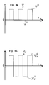
- the voltage amplification unit of the invention for example, in the drive / receiving unit is supplied with a voltage signal (U). It is a signal that alternates between an approximately constant upper (U O ) and an approximately constant lower (U U ) voltage value. This may be a rectangle or a rectangle-like, eg a trapezoidal signal. A pure square wave signal is usually difficult to achieve with the electronics; usually it is more of a trapezoidal waveform. The transition between these two values depends on the concrete design.
- the voltage difference (.DELTA.U) is smaller in the meaning of the invention than the voltage swing, which is required for reloading the piezoelectric unit with the desired amplitude.
- the voltage amplification unit is now designed so that a second voltage signal (U 2 ) is generated from the primary voltage signal (U), which is applied to the voltage amplifier unit, whose signal curve also alternates between an upper (U 2 O ) and a lower (U 2 U ) represents voltage value.
- this second voltage signal (U 2 ) is greater than the primary voltage signal (U).
- the frequencies are identical for both voltage signals U, U 2 .
- the voltage amplification unit so the voltage swing is increased without that the voltage swing (.DELTA.U 2 ) corresponding DC supply voltage must be provided.
- the basic idea is that there are alternately two constant voltages applied to the voltage amplification unit. The frequency of the change between these two voltage values is the frequency with which the piezoelectric unit should oscillate. However, the voltage difference between the two voltage values is less than the voltage difference necessary to achieve the desired amplitude of the oscillations of the piezoelectric unit. Therefore, this voltage amplifying unit is configured to increase the voltage difference to the required value. This is done in such a way that the piezoelectric unit is in each case subjected directly to the sections with a voltage value-preferably the greater magnitude of the voltage-of the primary voltage signal.
- the piezoelectric unit While the respective other section of the primary voltage signal with the smaller value of the voltage is applied to the voltage amplification unit, the piezoelectric unit is subjected essentially to the voltage difference of the primary voltage signal. This essentially results in at least a doubling of the voltage swing.
- An advantageous embodiment of the method according to the invention provides that, while the voltage amplification unit is subjected to a voltage value of the voltage signal (U U , U O ), in the voltage amplification unit at least one voltage storage unit with the voltage signal is substantially applied to the applied voltage value (U U ; U O ), and that, while the voltage amplifying unit is supplied with the correspondingly different voltage value of the voltage signal (U O ; U U ), the voltage amplifying unit is substantially transferred to the applied voltage value (U O ; U U ), and the piezoelectric Unit of the voltage storage unit is applied substantially with the differential voltage of the voltage signal (.DELTA.U).
- a voltage storage unit is charged to a voltage value and then transferred to the other voltage value.
- a voltage storage unit may be, for example, a capacitor. A signal portion of the voltage signal (U) is thus passed directly to the output or the piezoelectric unit, ie it is directly applied to it.
- the piezoelectric unit for example, with the voltage difference of the voltage signal (.DELTA.U) is applied, but with opposite signs, ie from a positive voltage value is a negative and a negative will be a positive.
- the magnitude of the voltage value is not necessarily identical to the magnitude of the voltage difference. This is due to the configuration of the voltage amplification unit and the components present therein and of the type of voltage signal (U).
- the signal is not only passed on to the piezoelectric unit, but also in the voltage amplification unit a voltage storage unit is simultaneously charged, which then becomes the second one during the second half cycle of the voltage signal (U) Half-wave of the second voltage signal (U 2 ) generated.
- a half-wave of the primary voltage signal (U) can be used twice to drive the piezoelectric unit.
- the object further relates to a field device for determination and / or monitoring a process variable of a medium, with a piezoelectric Unit, with a mechanically oscillatable unit, wherein the Piezoelectric unit with the mechanically oscillatable unit is coupled, and wherein the piezoelectric unit, the mechanical oscillatory unit to vibrate, or where the piezoelectric Unit vibrations of the mechanically oscillatable unit receives.
- a voltage amplifying unit is provided with an input and an output, whose input with a voltage signal (U) can be acted upon, and whose output is connected to the piezoelectric unit, wherein the voltage signal (U ) between two approximately constant voltage values (U U , U O ) with a differential voltage ( ⁇ U) between the two voltage values (U U , U O ) alternates in that at least one voltage storage unit with two sides is provided in the voltage amplification unit, which essentially corresponds to one Voltage value (U U , U O ) of the voltage signal is rechargeable, and which can be reloaded substantially to the corresponding other voltage value (U O , U U ) of the voltage signal that substantially the differential voltage of the voltage signal (.DELTA.U) can be tapped from the voltage storage unit , wherein the first side of the voltage storage unit with de m input is connected, and that the voltage amplifying unit comprises at least a first, a second and a
- a voltage storage unit is charged to at least a voltage value of the voltage signal (U).
- the voltage storage unit can also be charged to the voltage difference of the primary voltage signal.
- the voltage storage unit is connected to the output of the voltage amplification unit.
- the voltage storage unit is connected to the other voltage value of the voltage signal, ie it is reloaded.
- the output of the voltage storage unit is at least applied to the voltage difference of the voltage signal. Characterized in that the voltage storage unit is conductively connected to the output of the voltage amplifying unit, a discharge current flows. However, this also has an effect on the discharge voltage of the voltage storage unit. The following configurations will address this problem.
- An embodiment includes that the third switch unit essentially connects the second side of the voltage storage unit to the other voltage value (U U ) when the one voltage value (U O ) is present at the input.
- no third voltage source or no third potential is required, which is between ground and the other voltage value (U U ).
- An embodiment provides that the third switch unit essentially connects the second side of the voltage storage unit to ground when one of the voltage values (U O ) is present at the input. Grounding is present in most electronic device designs, making connection to ground relatively easy. In this embodiment, so to speak, the upper voltage value (U O ) is mirrored by the voltage amplifier unit.
- the voltage storage unit is a capacitor is.
- a capacitor as a voltage storage unit is the simplest Design. The capacitor is connected while a voltage value is applied, charged, i. he has two potentials with a u.a. through the Voltage value given difference. Is then the other Voltage value at one potential, so the other potential on forced another value, the potential difference is maintained.
- An advantageous embodiment provides that the frequency of Voltage signal (U) and the embodiment of Voltage amplification unit are matched to one another such that the Discharge voltage of the voltage storage unit during approximately one half period of the voltage signal (U) is approximately constant.
- the frequency of the voltage signal (U) is usually the Frequency with which the piezoelectric unit and thus the mechanical oscillating unit should swing.
- the discharge voltage at least approximately constant the result is as a drive signal in the piezoelectric Unit also a square wave signal.
- a more precise formulation of Condition for an approximately constant discharge voltage is that half Period of the voltage signal must be much smaller than the Discharge duration of the capacitor or the discharge time constant at ohmic Load.
- An embodiment includes that the capacity of Voltage storage unit is greater than the capacity of the piezoelectric Unit.
- the discharge duration e.g. of the capacitor results from his Capacitance and the resistance of the load resistor, over which the Capacitor is discharged.
- the load resistance to the piezoelectric unit which is why the condition that the Capacitance of the capacitor in the voltage amplification unit to be greater must be considered the capacity of the piezoelectric unit.
- Fig. 1 shows a block diagram of an embodiment of the field device 1, which is Liquiphanten, which is produced and marketed by the Applicant, inspired.
- the vibrations of the mechanically oscillatable unit 2 are from a control / evaluation unit 4 regulated or the oscillations of the oscillatory Unit 5 are evaluated by the control / evaluation unit 4, in order, e.g. from that the level of a medium in a container (not shown) determine.
- FIG. 2 the basic structure of an embodiment of the voltage amplifying unit 10 is shown with an input 10.1 and an output 10.2.
- the voltage amplification unit 10 is supplied with the primary voltage signal U, which alternates between the two approximately constant voltage values (U U , U O ), and in turn acts on the piezoelectric unit 5 with a second voltage signal U 2 , which is between the two approximately constant voltage values (U 2 U ; U 2 O ) alternates.
- the voltage amplification unit 10 and the piezoelectric unit 5 are therefore preferably located in the drive / receiving unit 3.
- the voltage amplification unit 10 has a voltage storage unit 11, which is designed here as a capacitor, and in this embodiment via three switch units 12: S1, S2 and S3.
- the capacitor is connected to the input 10.1 on one side and to the switch S3 on the other side. If, for example, the upper voltage value U 0 of the primary voltage signal U is present at the input 10. 1 of the voltage amplification unit 10, the switch units S1 and S3 are closed, and the switch unit S2 is opened. This causes the piezoelectric unit 5 is also acted upon by the voltage signal U. Thus, provided that the amount of U O is greater than the amount of U U , the upper voltage value U 2 O of the second voltage signal U 2 results directly from the upper voltage value U O of the primary voltage signal U. Further, the voltage storage unit 11 is grounded (this is useful if, for example, U O is ground) to the upper voltage value U O charge.
- the switch units S1 and S3 are open and the switch S2 is closed.
- the voltage storage unit 11 is reloaded and simultaneously applied to the piezoelectric unit 5.
- the piezoelectric unit 5 is supplied with the reversed-sign voltage value U O , which in this case is identical with the differential voltage of the primary voltage signal ⁇ U.
- the second voltage signal U 2 with which the voltage amplification unit 10 acts on the piezoelectric unit 5, thus has an upper and a lower voltage value, the amounts of which are essentially the upper voltage value U O - this is the higher value here - and the voltage difference ⁇ U correspond to the primary voltage signal.
- the voltage difference is the upper voltage value of the voltage signal U O.
- FIG. 4 shows a detailed illustration of the voltage amplification unit 10.
- the switch units S1 and S2 are designed here as MOSFETs and the switch unit S3 is a diode.
- an operational amplifier 13 is shown, which generates the voltage signal U.
- U the upper voltage value
- U 0 +20 V and the lower value U U -2.5 V the upper voltage value
- U U -2.5 V the lower value
- the gate of the p-channel MOSFET S1 is grounded, the gate of the n-channel MOSFET S2 is -2.5 V.
- the diode S3 is also connected to -2.5 V. If the upper voltage value U O with +20 V at the voltage amplification unit 10, the switch unit S1 is conductive, also the switch unit S3.
- the loss of the diode S3 is 0.7V.
- the MOSFET S1 blocks.
- the one terminal of the capacitor 11 is forced to - 2.5 V, which shifts the voltage potential of the other terminal to -24.3 V.
- the diode S3 blocks and the MOSFET S2 becomes conductive and passes the voltage of -24.3 V as the lower voltage value U 2 U of the second voltage signal U 2 to the piezoelectric unit 5 on.
- the capacitor 11 is discharged by a current flowing from the output. This results in a condition for the capacitance C of the capacitor 11, when the voltage of -24.3 V during a negative half cycle of the primary voltage signal U is not to change appreciably: T / 2 ⁇ ⁇ , ie half the period of the primary voltage signal
- U must be much smaller than the charging constant from the capacitance C of the capacitor 11 and the load resistance at the output.
- C applies load, ie, the capacitor in the circuit must be much greater than the load capacity (the load capacity C of the piezoelectric unit) to be.
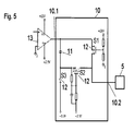
- FIG. 5 shows a further embodiment of the voltage amplification unit 10 is shown.
- the additional components resistors and capacitors in the switching units 12 S1 and S2 - the Minimizes crossover distortions that arise when S1 becomes conductive and S2 locks and vice versa. These inherited distortions depend inter alia. of the Speed of the FETs used and e.g. the gate bias off and are not of a fundamental nature.
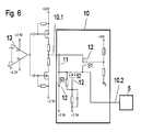
- Fig. 6 shows a further variant, in which by the operational amplifier 13 a signal is generated with the two constant voltage values +2.5 V and -2.5 V. By switching the components before the Voltage amplification unit is generated from this signal, a signal which alternates between -2.5V and +20V. The two work for that FETs as a switch. The capacitors load each against the applied voltage values. The real signal with the Oscillation frequency is thus generated by the operational amplifier 13 and the transformation of the signals to -2.5 V and +20 V is performed by the subsequent circuit before the actual voltage amplification unit 10.
- the advantage of this embodiment is that the voltage range + - 2.5 V to be covered by most operational amplifiers.
- the design the voltage amplifying unit 10 corresponds to the embodiment in FIG. 5.
Landscapes
- Physics & Mathematics (AREA)
- General Physics & Mathematics (AREA)
- Immunology (AREA)
- Pathology (AREA)
- Analytical Chemistry (AREA)
- Biochemistry (AREA)
- General Health & Medical Sciences (AREA)
- Life Sciences & Earth Sciences (AREA)
- Health & Medical Sciences (AREA)
- Chemical & Material Sciences (AREA)
- Acoustics & Sound (AREA)
- Electromagnetism (AREA)
- Thermal Sciences (AREA)
- Fluid Mechanics (AREA)
- Amplifiers (AREA)
- Measurement Of Levels Of Liquids Or Fluent Solid Materials (AREA)
- Gyroscopes (AREA)
Abstract
Description
- 1
- Feldgerät
- 2
- Mechanisch schwingfähigen Einheit
- 3
- Antriebs-/Empfangseinheit
- 4
- Regel-/Auswerteeinheit
- 5
- Piezo-elektrische Einheit
- 10
- Spannungsverstärkungseinheit
- 10.1
- Eingang
- 10.2
- Ausgang
- 11
- Spannungsspeichereinheit
- 12
- Schaltereinheit
- 13
- Operationsverstärker
Claims (8)
- Verfahren zur Ansteuerung einer piezo-elektrischen Einheit (5) in einem Feldgerät (1) zur Bestimmung und/oder Überwachung einer Prozessgröße eines Mediums,
wobei die piezo-elektrische Einheit (5) mit einer mechanisch schwingfähigen Einheit (2) gekoppelt ist,
wobei die piezo-elektrische Einheit (5) zu Schwingungen angeregt wird, bzw.
wobei die Schwingungen der piezo-elektrischen Einheit (5) detektiert werden,
dadurch gekennzeichnet, dass eine Spannungsverstärkungseinheit (10) mit einem Spannungssignal (U) beaufschlagt wird,
wobei das Spannungssignal (U) zwischen zwei annährend konstanten Spannungswerten (UU; UO) mit einer Differenzspannung (ΔU) zwischen den beiden Spannungswerten (UU; UO) alterniert, dass, während die Spannungsverstärkungseinheit (10) mit einem Spannungswert des Spannungssignals (UU; UO) beaufschlagt wird, die piezo-elektrische Einheit (5) ebenfalls mit diesem Spannungswert (UU; UO) beaufschlagt wird,
und dass, während die Spannungsverstärkungseinheit (10) mit dem entsprechend anderen Spannungswert des Spannungssignals (UO; UU) beaufschlagt wird, die piezo-elektrische Einheit (5) im Wesentlichen mit der Differenzspannung des Spannungssignals (ΔU) beaufschlagt wird. - Verfahren nach Anspruch 1,
dadurch gekennzeichnet, dass, während die Spannungsverstärkungseinheit (10) mit einem Spannungswert des Spannungssignals (UU; UO) beaufschlagt wird, in der Spannungsverstärkungseinheit (10) mindestens eine Spannungsspeichereinheit (11) mit dem Spannungssignal im Wesentlichen auf den anliegenden Spannungswert (UU; UO) aufgeladen wird,
und dass, während die Spannungsverstärkungseinheit (10) mit dem entsprechend anderen Spannungswert des Spannungssignals (UO; UU) beaufschlagt wird, die Spannungsverstärkungseinheit (10) im Wesentlichen auf den anliegenden Spannungswert (UO; UU) umgeladen wird, und die piezo-elektrische Einheit (5) von der Spannungsspeichereinheit (11) im Wesentlichen mit der Differenzspannung des Spannungssignals (ΔU) beaufschlagt wird. - Feldgerät (1) zur Bestimmung und/oder Überwachung einer Prozessgröße eines Mediums, mit einer piezo-elektrischen Einheit (5), mit einer mechanisch schwingfähigen Einheit (2),
wobei die piezo-elektrische Einheit (5) mit der mechanisch schwingfähigen Einheit (2) gekoppelt ist,
und
wobei die piezo-elektrische Einheit (5) die mechanisch schwingfähige Einheit (2) zu Schwingungen anregt, bzw. wobei die piezo-elektrische Einheit (5) Schwingungen der mechanisch schwingfähigen Einheit (2) empfängt,
dadurch gekennzeichnet, dass eine Spannungsverstärkungseinheit (10) mit einem Eingang (10.1) und einem Ausgang (10.2) vorgesehen ist, deren Eingang (10.1) mit einem Spannungssignal (U) beaufschlagbar ist, und deren Ausgang (10.2) mit der piezo-elektrischen Einheit (2) verbunden ist,
wobei das Spannungssignal (U) zwischen zwei annährend konstanten Spannungswerten (UU; UO) mit einer Differenzspannung (ΔU) zwischen den beiden Spannungswerten (UU; UO) alterniert, dass in der Spannungsverstärkungseinheit (10) mindestens eine Spannungsspeichereinheit (11) mit zwei Seiten vorgesehen ist, die im Wesentlichen auf einen Spannungswert (UU; UO) des Spannungssignals aufladbar ist, und die im Wesentlichen auf den entsprechend anderen Spannungswert (UO; UU) des Spannungssignals derart umladbar ist, dass im Wesentlichen die Differenzspannung des Spannungssignals (ΔU) von der Spannungsspeichereinheit (11) abgreifbar ist, wobei die erste Seite der Spannungsspeichereinheit (11) mit dem Eingang (10.1) verbunden ist,
und dass die Spannungsverstärkungseinheit (10) mindestens eine erste (S1), eine zweite (S2) und eine dritte Schaltereinheit (S3) aufweist,
wobei die erste Schaltereinheit (S1) den Ausgang (10.2) mit dem Eingang (10.1) verbindet, wenn ein Spannungswert (UO) am Eingang (10.1) anliegt,
wobei die zweite Schaltereinheit (S2) den Ausgang (10.2) mit der zweiten Seite der Spannungsspeichereinheit (11) verbindet, wenn der andere Spannungswerte (UU) am Eingang (10.1) anliegt,
und
wobei die dritte Schaltereinheit (S3) die zweite Seite der Spannungsspeichereinheit (11) mit einem Spannungswert im Wesentlichen zwischen dem anderen Spannungswert (UU) und Masse verbindet, wenn der eine Spannungswerte (UO) am Eingang (10.1) anliegt. - Feldgerät (1) nach Anspruch 3, dadurch gekennzeichnet, dass die dritte Schaltereinheit (S3) die zweite Seite der Spannungsspeichereinheit (11) im Wesentlichen mit dem anderen Spannungswert (UU) verbindet, wenn der eine Spannungswerte (UO) am Eingang (10.1) anliegt.
- Feldgerät (1) nach Anspruch 3, dadurch gekennzeichnet, dass die dritte Schaltereinheit (S3) die zweite Seite der Spannungsspeichereinheit (11) im Wesentlichen mit Masse verbindet, wenn der eine Spannungswerte (UO) am Eingang (10.1) anliegt.
- Feldgerät (1) nach Anspruch 3,
dadurch gekennzeichnet, dass es sich bei der Spannungsspeichereinheit (11) um einen Kondensator handelt. - Feldgerät (1) nach Anspruch 3 oder 6, dadurch gekennzeichnet, dass die Frequenz des Spannungssignals (U) und die Ausgestaltung der Spannungsverstärkungseinheit (10) derartig aufeinander abgestimmt sind, dass die Entladespannung der Spannungsspeichereinheit (11) während annährend einer halben Periodendauer des Spannungssignals (U) annährend konstant ist.
- Feldgerät (1) nach Anspruch 7, dadurch gekennzeichnet, dass die Kapazität der Spannungsspeichereinheit (11) größer ist als die Kapazität der piezo-elektrischen Einheit (5).
Applications Claiming Priority (2)
| Application Number | Priority Date | Filing Date | Title |
|---|---|---|---|
| DE10331428 | 2003-07-10 | ||
| DE2003131428 DE10331428B4 (de) | 2003-07-10 | 2003-07-10 | Feldgerät zur Bestimmung und/oder Überwachung einer Prozessgröße |
Publications (2)
| Publication Number | Publication Date |
|---|---|
| EP1498702A1 true EP1498702A1 (de) | 2005-01-19 |
| EP1498702B1 EP1498702B1 (de) | 2008-11-26 |
Family
ID=33461907
Family Applications (1)
| Application Number | Title | Priority Date | Filing Date |
|---|---|---|---|
| EP20040016040 Expired - Lifetime EP1498702B1 (de) | 2003-07-10 | 2004-07-08 | Feldgerät zur Bestimmung und/oder Überwachung einer Prozessgrösse |
Country Status (2)
| Country | Link |
|---|---|
| EP (1) | EP1498702B1 (de) |
| DE (2) | DE10331428B4 (de) |
Families Citing this family (2)
| Publication number | Priority date | Publication date | Assignee | Title |
|---|---|---|---|---|
| DE102005036872B4 (de) | 2005-08-02 | 2016-03-24 | Vega Grieshaber Kg | Vorrichtung zur Vibrations-Füllstand-Grenzstanderfassung und Verfahren zur Vibrations-Füllstand-Grenzstanderfassung |
| DE102011090014A1 (de) * | 2011-12-28 | 2013-07-04 | Endress + Hauser Gmbh + Co. Kg | Vorrichtung zur Bestimmung und/oder Überwachung mindestens einer Prozessgröße |
Citations (3)
| Publication number | Priority date | Publication date | Assignee | Title |
|---|---|---|---|---|
| EP0810423A2 (de) * | 1996-05-29 | 1997-12-03 | VEGA Grieshaber KG | Vibrationsresonator, Verfahren zum Betreiben eines solchen Vibrationsresonators und Vibrations-Füllstand-Grenzschalter mit einem solchen Vibrationsresonator |
| DE19720519A1 (de) * | 1997-05-16 | 1998-11-19 | Pepperl & Fuchs | Vorrichtung zur Feststellung und/oder Überwachung eines Füllstandes eines Mediums in einem Behälter |
| US5895848A (en) * | 1996-01-16 | 1999-04-20 | Flowline Inc. | Apparatus and method for level sensing in a container |
Family Cites Families (3)
| Publication number | Priority date | Publication date | Assignee | Title |
|---|---|---|---|---|
| GB2242023B (en) * | 1990-03-14 | 1993-09-08 | Federal Ind Ind Group Inc | Improvements in acoustic ranging systems |
| US5237209A (en) * | 1992-03-02 | 1993-08-17 | Analog Devices, Inc. | Bipolar voltage doubler circuit |
| DE10057974A1 (de) * | 2000-11-22 | 2002-05-23 | Endress Hauser Gmbh Co | Verfahren und Vorrichtung zur Feststellung und/oder Überwachung des Füllstands eines Mediums in einem Behälter bzw. zur Ermittlung der Dichte eines Mediums in einem Behälter |
-
2003
- 2003-07-10 DE DE2003131428 patent/DE10331428B4/de not_active Expired - Fee Related
-
2004
- 2004-07-08 DE DE200450008512 patent/DE502004008512D1/de not_active Expired - Lifetime
- 2004-07-08 EP EP20040016040 patent/EP1498702B1/de not_active Expired - Lifetime
Patent Citations (3)
| Publication number | Priority date | Publication date | Assignee | Title |
|---|---|---|---|---|
| US5895848A (en) * | 1996-01-16 | 1999-04-20 | Flowline Inc. | Apparatus and method for level sensing in a container |
| EP0810423A2 (de) * | 1996-05-29 | 1997-12-03 | VEGA Grieshaber KG | Vibrationsresonator, Verfahren zum Betreiben eines solchen Vibrationsresonators und Vibrations-Füllstand-Grenzschalter mit einem solchen Vibrationsresonator |
| DE19720519A1 (de) * | 1997-05-16 | 1998-11-19 | Pepperl & Fuchs | Vorrichtung zur Feststellung und/oder Überwachung eines Füllstandes eines Mediums in einem Behälter |
Also Published As
| Publication number | Publication date |
|---|---|
| DE10331428B4 (de) | 2005-07-28 |
| DE502004008512D1 (de) | 2009-01-08 |
| DE10331428A1 (de) | 2005-02-24 |
| EP1498702B1 (de) | 2008-11-26 |
Similar Documents
| Publication | Publication Date | Title |
|---|---|---|
| DE2616678B2 (de) | Oszillatorschaltung | |
| EP1248369A2 (de) | Näherungssensor und Verfahren zu seinem Betrieb | |
| DE69229289T2 (de) | Treiberschaltung für Vibrationsmotor | |
| DE4322388C2 (de) | Schaltungsanordnung zum sicheren Anschwingen von Ultraschalldesintegratoren | |
| DE102007016642B4 (de) | Elektromechanisches System und Verfahren zum Betrieb eines elektromechanischen Systems | |
| DE102007059709B4 (de) | Kapazitiver Sensor | |
| DE4036618C3 (de) | Vorrichtung zum Ansteuern eines piezoelektrischen Vibrators | |
| WO2003060482A2 (de) | Vorrichtung zur messung der viskosität und/oder der dichte | |
| DE2746371A1 (de) | Akustische alarmanlage mit hoher ausgangsleistung | |
| DE69819072T2 (de) | Ultraschallwellenmotoranordnung und elektronisches Gerät mit Ultraschallwellenmotoranordnung | |
| EP0578021A2 (de) | Hörgerät | |
| DE19720519C2 (de) | Vorrichtung zur Feststellung und/oder Überwachung eines Füllstandes eines Mediums in einem Behälter | |
| DE2000703A1 (de) | Frequenzmodulierbarer Oszillator | |
| DE19646198A1 (de) | Ladungspumpschaltung zum Ansteuern einer integrierten Halbleiterschaltung | |
| DE10023306C2 (de) | Verfahren zur Ansteuerung von piezoelektrischen Antrieben in Füllstandmessgeräten | |
| EP1498702B1 (de) | Feldgerät zur Bestimmung und/oder Überwachung einer Prozessgrösse | |
| EP1570243B1 (de) | Vorrichtung zum betreiben einer schwingfähigen einheit eines vibrationsresonators | |
| EP2979311B1 (de) | Schaltungsanordnung und verfahren zur ansteuerung eines piezotransformators | |
| EP1920535B1 (de) | Oszillatorschaltung sowie verfahren zur beeinflussung, steuerung oder regelung der frequenz eines oszillators | |
| EP3537177B1 (de) | Vorrichtung und verfahren zur übertragerfreien ansteuerung eines ultraschalltransducers | |
| EP0343403B1 (de) | Schaltungsanordnung zur Selbsterregung eines mechanischen Schwingsystems zu Eigenresonanzschwingungen | |
| DE10162912B4 (de) | Quarzoszillatorschaltung | |
| DE10047379B4 (de) | Bauelement mit akustisch aktivem Material | |
| DE102019119911A1 (de) | Verfahren und Generator zur Charakterisierung eines Schwingsystems | |
| DE19719440A1 (de) | Oszillatorschaltung |
Legal Events
| Date | Code | Title | Description |
|---|---|---|---|
| PUAI | Public reference made under article 153(3) epc to a published international application that has entered the european phase |
Free format text: ORIGINAL CODE: 0009012 |
|
| AK | Designated contracting states |
Kind code of ref document: A1 Designated state(s): AT BE BG CH CY CZ DE DK EE ES FI FR GB GR HU IE IT LI LU MC NL PL PT RO SE SI SK TR |
|
| AX | Request for extension of the european patent |
Extension state: AL HR LT LV MK |
|
| 17P | Request for examination filed |
Effective date: 20050326 |
|
| AKX | Designation fees paid |
Designated state(s): DE FR GB IT |
|
| 17Q | First examination report despatched |
Effective date: 20061124 |
|
| GRAP | Despatch of communication of intention to grant a patent |
Free format text: ORIGINAL CODE: EPIDOSNIGR1 |
|
| GRAS | Grant fee paid |
Free format text: ORIGINAL CODE: EPIDOSNIGR3 |
|
| GRAA | (expected) grant |
Free format text: ORIGINAL CODE: 0009210 |
|
| AK | Designated contracting states |
Kind code of ref document: B1 Designated state(s): DE FR GB IT |
|
| REG | Reference to a national code |
Ref country code: GB Ref legal event code: FG4D Free format text: NOT ENGLISH |
|
| REF | Corresponds to: |
Ref document number: 502004008512 Country of ref document: DE Date of ref document: 20090108 Kind code of ref document: P |
|
| PLBE | No opposition filed within time limit |
Free format text: ORIGINAL CODE: 0009261 |
|
| STAA | Information on the status of an ep patent application or granted ep patent |
Free format text: STATUS: NO OPPOSITION FILED WITHIN TIME LIMIT |
|
| 26N | No opposition filed |
Effective date: 20090827 |
|
| REG | Reference to a national code |
Ref country code: FR Ref legal event code: PLFP Year of fee payment: 13 |
|
| REG | Reference to a national code |
Ref country code: FR Ref legal event code: PLFP Year of fee payment: 14 |
|
| REG | Reference to a national code |
Ref country code: DE Ref legal event code: R081 Ref document number: 502004008512 Country of ref document: DE Owner name: ENDRESS+HAUSER SE+CO. KG, DE Free format text: FORMER OWNER: ENDRESS + HAUSER GMBH + CO. KG, 79689 MAULBURG, DE |
|
| REG | Reference to a national code |
Ref country code: FR Ref legal event code: PLFP Year of fee payment: 15 |
|
| PGFP | Annual fee paid to national office [announced via postgrant information from national office to epo] |
Ref country code: GB Payment date: 20190719 Year of fee payment: 16 |
|
| GBPC | Gb: european patent ceased through non-payment of renewal fee |
Effective date: 20200708 |
|
| PG25 | Lapsed in a contracting state [announced via postgrant information from national office to epo] |
Ref country code: GB Free format text: LAPSE BECAUSE OF NON-PAYMENT OF DUE FEES Effective date: 20200708 |
|
| PGFP | Annual fee paid to national office [announced via postgrant information from national office to epo] |
Ref country code: IT Payment date: 20220726 Year of fee payment: 19 Ref country code: DE Payment date: 20220720 Year of fee payment: 19 |
|
| PGFP | Annual fee paid to national office [announced via postgrant information from national office to epo] |
Ref country code: FR Payment date: 20220720 Year of fee payment: 19 |
|
| REG | Reference to a national code |
Ref country code: DE Ref legal event code: R119 Ref document number: 502004008512 Country of ref document: DE |
|
| PG25 | Lapsed in a contracting state [announced via postgrant information from national office to epo] |
Ref country code: DE Free format text: LAPSE BECAUSE OF NON-PAYMENT OF DUE FEES Effective date: 20240201 |
|
| PG25 | Lapsed in a contracting state [announced via postgrant information from national office to epo] |
Ref country code: FR Free format text: LAPSE BECAUSE OF NON-PAYMENT OF DUE FEES Effective date: 20230731 |
|
| PG25 | Lapsed in a contracting state [announced via postgrant information from national office to epo] |
Ref country code: IT Free format text: LAPSE BECAUSE OF NON-PAYMENT OF DUE FEES Effective date: 20230708 |