EP1498380A1 - Emergency brake device for elevator - Google Patents
Emergency brake device for elevator Download PDFInfo
- Publication number
- EP1498380A1 EP1498380A1 EP02720525A EP02720525A EP1498380A1 EP 1498380 A1 EP1498380 A1 EP 1498380A1 EP 02720525 A EP02720525 A EP 02720525A EP 02720525 A EP02720525 A EP 02720525A EP 1498380 A1 EP1498380 A1 EP 1498380A1
- Authority
- EP
- European Patent Office
- Prior art keywords
- braking
- mechanism portion
- sheave
- shaft
- brake shoe
- Prior art date
- Legal status (The legal status is an assumption and is not a legal conclusion. Google has not performed a legal analysis and makes no representation as to the accuracy of the status listed.)
- Withdrawn
Links
Images




Classifications
-
- B—PERFORMING OPERATIONS; TRANSPORTING
- B66—HOISTING; LIFTING; HAULING
- B66B—ELEVATORS; ESCALATORS OR MOVING WALKWAYS
- B66B5/00—Applications of checking, fault-correcting, or safety devices in elevators
- B66B5/02—Applications of checking, fault-correcting, or safety devices in elevators responsive to abnormal operating conditions
-
- B—PERFORMING OPERATIONS; TRANSPORTING
- B66—HOISTING; LIFTING; HAULING
- B66B—ELEVATORS; ESCALATORS OR MOVING WALKWAYS
- B66B5/00—Applications of checking, fault-correcting, or safety devices in elevators
- B66B5/02—Applications of checking, fault-correcting, or safety devices in elevators responsive to abnormal operating conditions
- B66B5/04—Applications of checking, fault-correcting, or safety devices in elevators responsive to abnormal operating conditions for detecting excessive speed
-
- B—PERFORMING OPERATIONS; TRANSPORTING
- B66—HOISTING; LIFTING; HAULING
- B66B—ELEVATORS; ESCALATORS OR MOVING WALKWAYS
- B66B15/00—Main component parts of mining-hoist winding devices
- B66B15/02—Rope or cable carriers
- B66B15/04—Friction sheaves; "Koepe" pulleys
-
- B—PERFORMING OPERATIONS; TRANSPORTING
- B66—HOISTING; LIFTING; HAULING
- B66D—CAPSTANS; WINCHES; TACKLES, e.g. PULLEY BLOCKS; HOISTS
- B66D5/00—Braking or detent devices characterised by application to lifting or hoisting gear, e.g. for controlling the lowering of loads
- B66D5/02—Crane, lift hoist, or winch brakes operating on drums, barrels, or ropes
- B66D5/06—Crane, lift hoist, or winch brakes operating on drums, barrels, or ropes with radial effect
- B66D5/08—Crane, lift hoist, or winch brakes operating on drums, barrels, or ropes with radial effect embodying blocks or shoes
-
- B—PERFORMING OPERATIONS; TRANSPORTING
- B66—HOISTING; LIFTING; HAULING
- B66D—CAPSTANS; WINCHES; TACKLES, e.g. PULLEY BLOCKS; HOISTS
- B66D5/00—Braking or detent devices characterised by application to lifting or hoisting gear, e.g. for controlling the lowering of loads
- B66D5/02—Crane, lift hoist, or winch brakes operating on drums, barrels, or ropes
- B66D5/24—Operating devices
- B66D5/30—Operating devices electrical
Definitions
- the present invention relates to an emergency braking apparatus applied to an elevator in which a car and a counterweight are suspended at a first end and a second end, respectively, of a main rope wound around a sheave, and functions such that ascent of the car is stopped when the car ascends at greater than or equal to a rated velocity, for example.
- elevators are constructed such that a car and a counterweight are suspended at a first end and a second end, respectively, of main ropes wound around a drive sheave of a hoisting machine.
- a brake designed to apply a braking force as input to an electric motor is simultaneously interrupted is mounted to the hoisting machine in order to control inertial rotation of the hoisting machine automatically.
- an emergency stopping apparatus for gripping opposite sides of a guide rail with strong force is disposed on a side of the car, and the emergency stopping apparatus operates to stop the descent of the car if the speed governor detects an overspeed in the descent velocity.
- a supplementary emergency braking apparatus that functions independently from the brake and starts prior to the emergency stopping apparatus is required to further increase the safety level of the elevator.
- This supplementary emergency braking apparatus must generate a controlled reproducible braking effect, particularly when the elevator is moving in an upward direction. More specifically, in elevators of this kind, there is a danger that the car may suddenly ascend at greater than or equal to the rated velocity due to failure of the brake or due to the hoisting machine running out of control, etc. If the car ascends at greater than or equal to the rated velocity, there is a risk that the counterweight may collide with buffers at greater than or equal to design velocity, injuring passengers inside the car.
- a supplementary emergency braking apparatus provided with a mechanism for seizing a guide rail or a main rope directly has been installed on the same side as the counterweight, and if the car ascends at greater than or equal to a rated velocity, the supplementary emergency braking apparatus operates to seize the guide rail or the main rope directly and stop the ascent of the car.
- some disadvantages with this conventional countermeasure are that installation space is required for the supplementary emergency braking apparatus, that it may lead to damage to the guide rail or the main rope and to accidents, and also that the construction is complicated, giving rise to increases in equipment costs.
- an emergency braking apparatus in which a pressing body 3 is disposed facing a drive sheave 1 on an opposite side of a main rope 2 wound over the drive sheave 1 and a wedge-shaped braking member 4 between the drive sheave 1 and the pressing body 3.
- this conventional emergency braking apparatus it is claimed that during braking the braking member 4 is pushed in between the drive sheave 1 and the pressing body 3 and the main rope 2 is grasped between the drive sheave 1 and the braking member 4, thus achieving an appropriate braking effect.
- some disadvantages with this conventional emergency braking apparatus are that installation space is required for the apparatus and that it may lead to damage to the main rope and to accidents. Another disadvantage is that after activation this conventional emergency braking apparatus must be reset to its standby state manually.
- an emergency braking apparatus is proposed that is provided with: a drive sheave 6 fixed to a shaft 5; a star-shaped brake wheel 7 rotatably mounted to the shaft 5 so as to place a brake shoe 8 in contact with an annular end surface 6a of the drive sheave 6; a spring member 9 for pressing the star-shaped brake element 7 against the drive sheave 6; and an activating mechanism 12 constructed such that a braking bolt 11 is inserted and removed from between spokes 7a of the star-shaped brake wheel 7 by electromagnetic force from a solenoid 10.
- Another disadvantage with this conventional emergency braking apparatus is that because braking of the drive sheave 6 commences after the braking bolt 11 has been inserted between the spokes 7a and comes into contact with a spoke 7a, a time lag between activation and the commencement of braking arises due to the construction, and the car will increase velocity during this temporal delay.
- the present invention aims to solve the above problems and an object of the present invention is to provide an inexpensive elevator emergency braking apparatus operating to swiftly decelerate or stop a car when the car ascends at greater than or equal to a rated velocity, and not requiring special installation space.
- an elevator emergency braking apparatus for performing braking of an elevator in which a car is suspended at a first end of a main rope wound around an outer ring of a sheave and a counterweight is suspended at a second end of the main rope includes:
- an elevator emergency braking apparatus for performing braking of an elevator in which a car is suspended at a first end of a main rope wound around an outer ring of a sheave and a counterweight is suspended at a second end of the main rope includes:
- Figure 1 is a schematic diagram showing an elevator mounted with an emergency braking apparatus according to Embodiment 1 of the present invention
- Figure 2 is an enlarged partial side elevation showing a standby state of the emergency braking apparatus according to Embodiment 1 of the present invention
- Figure 3 is an enlarged partial side elevation showing an activated state of the emergency braking apparatus according to Embodiment 1 of the present invention
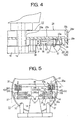
- Figure 4 is a cross section taken along line IV - IV in Figure 2 viewed from the direction of the arrows.
- a hoisting machine 22 is installed in a machine room 21 in an upper portion of a hoistway 20
- a car 23 is disposed so as to be guided by car guide rails 24 and be able to ascend and descend inside the hoistway 20
- a counterweight 25 is disposed so as to be guided by counterweight guide rails 26 and be able to ascend and descend inside the hoistway 20.
- a main rope 27 is wound around a drive sheave 28 of the hoisting machine 22 and a deflector sheave 29 installed inside the machine room 21.
- the car 23 is suspended at a first end of the main rope 27, and the counterweight 25 at a second end of the main rope 27.
- an emergency braking apparatus 100 is mounted to the drive sheave 28.
- the hoisting machine 22, as shown in Figure 2 is disposed inside the machine room 21 such that a frame 18 thereof is fixed to a floor surface of the machine room 21.
- the drive sheave 28 (a sheave) of the hoisting machine 21, as shown in Figure 4 is constituted by: a hub 28a; spokes 28b extending radially from the hub 28a; and an annular outer ring 28c linked to the hub 28a by means of the spokes 28b, the hub 28a being rotatably mounted to the frame 18 around an axle 19.
- Rope grooves 28d are formed on an outer peripheral wall surface of the outer ring 28c.
- the deflector sheave 29 (a sheave) is also constructed in a similar manner to the drive sheave 28.
- a brake and emergency stopping apparatus are provided.
- the emergency braking apparatus 100 is constituted by: a braking mechanism portion 30 for braking the drive sheave 28; and an activating mechanism portion 40 for activating the braking mechanism portion 30.
- the braking mechanism portion 30 is constituted by: a base portion 31; a pair of bolts 32 functioning as a guide member disposed so as to stand parallel to each other on this base portion 31; a movable portion 33 mounted to the pair of bolts 32 so as to be reciprocally movable in an axial direction; a brake shoe 34 mounted to a tip of this movable portion 33; adjusting nuts 35 respectively screwed onto a root portion of each of the bolts 32; and springs 36 respectively disposed in a compressed state between each of the adjusting nuts 35 and the movable portion 33.
- the brake shoe 34 is formed integrally with the movable portion 33 so as to cover head portions 32a of the bolts 32.
- the movable portion 33 is placed in a state of contact with the head portions 32a of the bolts 32 by the force of the springs 36.
- the base portion 31 of this braking mechanism portion 30 is mounted to the frame 18 so as to be pivotable about a shaft 38 parallel to the axle 19, the braking mechanism portion 30 adopting: a standby position in which the brake shoe 34 is separated from an inner circumferential wall surface 28e of the outer ring 28c of the drive sheave 28; and a braking position in which the braking mechanism portion 30 is placed in contact with a stopper 37 disposed so as to stand upright on the frame 18 and the brake shoe 34 is placed in contact with the inner circumferential wall surface 28e of the outer ring 28c of the drive sheave 28.
- the shaft 38 (a first shaft) is disposed inside the drive sheave 28 on a like side as the deflector sheave 29 relative to an up-down line (a vertical line) passing through a central axis of the axle 19 in Figure 2 and in a region between a left-right line (a horizontal line) passing through the central axis of the axle 19 and the perpendicular line so as to enable the standby position and the braking position to be adopted.
- the activating mechanism portion 40 is constituted by: a solenoid coil 41; and a plunger 42 composed of a magnetic material. This activating mechanism portion 40 is mounted to the frame 18 such that the direction of movement of the plunger 42 is vertical, a projecting end of the plunger 42 being linked to the movable portion 33 so as to be pivotable around a shaft 44 parallel to the shaft 38.
- an emergency braking apparatus 100 constructed in this manner, when an electric current is passed through the solenoid coil 41, the plunger 42 is magnetically attracted and retracts (moves upward in Figure 2), stopping when a stopper 42a comes into contact with a main body portion of the solenoid coil 41.
- the retracting force of this plunger 42 is transmitted to the braking member 30 by means of the movable portion 33, and the braking member 30 pivots around the shaft 38 counterclockwise in Figure 2.
- This braking member 30, as shown in Figure 2 is maintained in the standby position by the stopper 42a being placed in contact with the main body portion of the solenoid coil 41.
- the braking mechanism portion 30 moves toward the base portion 31 together with the rotation of the drive sheave 28 (clockwise in Figure 2) such that the movable portion 33 is guided by the bolts 32, pivots further while compressing the springs 36, and stops when placed in contact with the stopper 37, assuming the braking position shown in Figure 3. Then, a pressing force resulting from the compression of the springs 36 acts on the inner circumferential wall surface 28e by means of the brake shoe 34, generating a braking force between the brake shoe 34 and the inner circumferential wall surface 28e, and the car 23 is decelerated or stopped.
- an emergency braking apparatus 100 functions as an ascent safety apparatus capable of operating swiftly to perform deceleration or stopping of the car 23 when the ascent velocity of the car 23 exceeds a rated velocity.
- an ascent safety apparatus capable of operating swiftly to perform deceleration or stopping of the car 23 when the ascent velocity of the car 23 exceeds a rated velocity.
- the amount of pivoting from the standby position of the braking mechanism portion 30 to the braking position is constant, the amount of compression in the springs 36 is also constant, enabling the ascending car 23 to be decelerated or stopped by a constant braking force irrespective of velocity.
- adjusting nuts 35 are provided, if the adjusting nuts 35 are adjusted so that the amount of compression in the springs 36 is increased at the standby position, the pressing force of the brake shoe 34 on the inner circumferential wall surface 28e during braking can be increased. In other words, the braking force can be adjusted arbitrarily.
- the braking function is reliably exhibited by the brake shoe 34 cutting into the inner circumferential wall surface 28e in a wedging effect, thereby improving the safety level.
- this emergency braking apparatus 100 because the braking mechanism portion 30 can be returned from the braking position to the standby position by passing an electric current to the solenoid coil 41, a manual operation for resetting the emergency braking apparatus is also no longer necessary. Thus, because the emergency braking apparatus 100 can be activated repeatedly, the emergency braking apparatus 100 can also be activated when the car 23 is at a floor to stop rotation of the drive sheave 28. Thus, sudden abnormal ascent of the car 23 while passengers are boarding and leaving is reliably prevented, further increasing the safety level.
- the emergency braking apparatus 100 is constituted by a braking mechanism portion 30 including a base portion 31, a pair of bolts 32 disposed so as to stand on the base portion 31, a movable portion 33 movably disposed along shafts of the bolts 32 so as to be guided by the bolts 32, and having a brake shoe 34 mounted integrally to a tip, and springs 36 for forcing the movable portion 33 toward head portions 32a of the bolts 32; and an activating mechanism portion 40 including a solenoid coil 41 and a plunger 42, the construction of the apparatus is simplified, enabling cost reductions.
- the emergency braking apparatus 100 is disposed on a like side of a vertical line passing through the axle 19 as a deflector sheave 29, but the emergency braking apparatus 100 may also be disposed on an opposite side of the vertical line passing through the axle 19 from the deflector sheave 29.
- the emergency braking apparatus 100 functions as a descent safety apparatus and the emergency braking apparatus 100 operates swiftly to decelerate or stop the car 23 if abnormal velocity of the car 23 in a downward direction is detected.
- sudden dropping of the car while passengers are boarding and leaving can be prevented by operating the emergency braking apparatus 100 to prevent rotation of the drive sheave 23 that gives rise to the dropping of the car 23.
- Figure 5 is an enlarged partial side elevation showing a standby state of an emergency braking apparatus according to Embodiment 2 of the present invention.
- a braking mechanism portion 30 mounted so as to be pivotable around a shaft 38 (a first shaft) is disposed inside a drive sheave 28 and a braking position on a like side of a vertical line passing through a central axis of an axle 19 as a deflector sheave 29 and in a region between a horizontal line and the vertical line passing through the central axis of the axle 19 so as to adopt a standby position
- a braking mechanism portion 30 mounted so as to be pivotable around a shaft 38 (a second shaft) is disposed inside the drive sheave 28 on an opposite side of the vertical line passing through the central axis of the axle 19 from the deflector sheave 29 and in a region between a horizontal line and the vertical line passing through the central axis of the axle 19 so as to adopt a standby position and a braking position.
- the two emergency braking apparatuses 100 are disposed
- Embodiment 2 during normal operation of the car 23, an electric current is passed through the solenoid coils 41 of both of the emergency braking apparatuses 100 to maintain them in the standby position.
- Embodiment 2 because two emergency braking apparatuses 100 are deployed, and the first emergency braking apparatus 100 functions as an ascent safety apparatus, and the second emergency braking apparatus 100 functions as a descent safety apparatus, if abnormal upward or downward velocity of the car 23 is detected, the emergency braking apparatus 100 operates swiftly to decelerate or stop the car 23, improving the safety level.
- the two emergency braking apparatuses 100 are operated when the car 23 is at a floor in order to prevent rotation of the drive sheave 23 that gives rise to rising and dropping of the car 23, sudden rising and dropping of the car can be prevented while passengers are boarding and leaving, raising the safety level.
- the two emergency braking apparatuses 100 are disposed symmetrically relative to a vertical line passing through the axle 19, but it is not absolutely necessary for the two emergency braking apparatuses 100 to be disposed symmetrically relative to the vertical line passing through the axle 19; it is only necessary for the braking mechanism portion 30 of each of the emergency braking apparatuses 100 to be disposed so as to be able to adopt the standby position and the braking position.
- the braking mechanism portion 30 when the passage of electric current to the solenoid coil 41 of an emergency braking apparatus 100 is stopped, the braking mechanism portion 30 is set to the braking position by pivoting around the shaft 38 under its own weight, but the activating mechanism portion 40 may also be equipped with a spring for forcing the plunger 42 toward the braking mechanism portion 30, and when the passage of electric current to the solenoid coil 41 is stopped, the plunger 42 is moved by the force of the spring, the braking mechanism portion 30 thereby being set to the braking position by pivoting around the shaft 38.
- the amount of time from activation to the commencement of braking is shortened, enabling increases in the velocity of the car 23 resulting from the time lag from activation to the commencement of braking to be further suppressed.
- the plunger 42 and the movable portion 33 are linked so as to be pivotable about the shaft 44, but the plunger 42 and the movable portion 33 may also be linked by a universal joint. In that case, the transmission of force between the plunger 42 and the movable portion 33 is smooth, and it is no longer necessary to ensure the installation position of the activating mechanism portion 40 with high precision, facilitating assembly of the emergency braking apparatus 100.
- the emergency braking apparatus 100 is installed in the drive sheave 28, but similar effects can also be achieved if the emergency braking apparatus 100 is installed in the deflector sheave 29.
Landscapes
- Engineering & Computer Science (AREA)
- Mechanical Engineering (AREA)
- Cage And Drive Apparatuses For Elevators (AREA)
- Maintenance And Inspection Apparatuses For Elevators (AREA)
- Braking Arrangements (AREA)
Abstract
The present invention provides an inexpensive elevator emergency
braking apparatus operating to swiftly decelerate or stop a car when the
car ascends at greater than or equal to a rated velocity, and not requiring
special installation space.
The elevator emergency braking apparatus includes a braking
mechanism portion mounted inside a sheave so as to be pivotable around a
first shaft parallel to an axle of the sheave and so as to be positioned on a
like side as a counterweight relative to a vertical line passing through the
axle, and being provided with a brake shoe at an opposite end from the first
shaft, the braking mechanism portion adopting a standby position in which
the brake shoe is separated from an inner circumferential wall surface of
an outer ring of the sheave and a braking position in which the brake shoe
contacts the inner circumferential wall surface of the outer ring; and
an activating mechanism portion for maintaining the braking mechanism portion in the standby position when not braking and maintaining the braking mechanism portion in the braking position when braking.
an activating mechanism portion for maintaining the braking mechanism portion in the standby position when not braking and maintaining the braking mechanism portion in the braking position when braking.
Description
The present invention relates to an emergency braking apparatus
applied to an elevator in which a car and a counterweight are suspended at
a first end and a second end, respectively, of a main rope wound around a
sheave, and functions such that ascent of the car is stopped when the car
ascends at greater than or equal to a rated velocity, for example.
Generally, elevators are constructed such that a car and a
counterweight are suspended at a first end and a second end, respectively,
of main ropes wound around a drive sheave of a hoisting machine. A
brake designed to apply a braking force as input to an electric motor is
simultaneously interrupted is mounted to the hoisting machine in order to
control inertial rotation of the hoisting machine automatically. In addition,
irrespective of the type of hoisting machine, or how the ropes are hung, etc,
there is a risk that an elevator will exceed the capacity of normal safety
apparatus if the ropes snap, or if the descent velocity of the car increases
significantly for some other unforeseeable reason. For that reason, if the
descent velocity of the car reaches a constant ratio of overspeed, it is
necessary to stop the descent thereof completely. Thus, an emergency
stopping apparatus for gripping opposite sides of a guide rail with strong
force is disposed on a side of the car, and the emergency stopping apparatus
operates to stop the descent of the car if the speed governor detects an
overspeed in the descent velocity.
In addition, a supplementary emergency braking apparatus that
functions independently from the brake and starts prior to the emergency
stopping apparatus is required to further increase the safety level of the
elevator. This supplementary emergency braking apparatus must
generate a controlled reproducible braking effect, particularly when the
elevator is moving in an upward direction. More specifically, in elevators
of this kind, there is a danger that the car may suddenly ascend at greater
than or equal to the rated velocity due to failure of the brake or due to the
hoisting machine running out of control, etc. If the car ascends at greater
than or equal to the rated velocity, there is a risk that the counterweight
may collide with buffers at greater than or equal to design velocity, injuring
passengers inside the car.
Thus, conventionally, a supplementary emergency braking
apparatus provided with a mechanism for seizing a guide rail or a main
rope directly has been installed on the same side as the counterweight, and
if the car ascends at greater than or equal to a rated velocity, the
supplementary emergency braking apparatus operates to seize the guide
rail or the main rope directly and stop the ascent of the car. However,
some disadvantages with this conventional countermeasure are that
installation space is required for the supplementary emergency braking
apparatus, that it may lead to damage to the guide rail or the main rope
and to accidents, and also that the construction is complicated, giving rise
to increases in equipment costs.
In Japanese Patent Laid-Open No. HEI 6-199483 (Gazette), as
shown in Figure 6, an emergency braking apparatus is proposed in which a
pressing body 3 is disposed facing a drive sheave 1 on an opposite side of a
main rope 2 wound over the drive sheave 1 and a wedge-shaped braking
member 4 between the drive sheave 1 and the pressing body 3. In this
conventional emergency braking apparatus, it is claimed that during
braking the braking member 4 is pushed in between the drive sheave 1 and
the pressing body 3 and the main rope 2 is grasped between the drive
sheave 1 and the braking member 4, thus achieving an appropriate braking
effect. However, some disadvantages with this conventional emergency
braking apparatus are that installation space is required for the apparatus
and that it may lead to damage to the main rope and to accidents.
Another disadvantage is that after activation this conventional emergency
braking apparatus must be reset to its standby state manually.
In addition, in Japanese Patent Laid-Open No. HEI 5-193860
(Gazette), as shown in Figures 7 to 9, an emergency braking apparatus is
proposed that is provided with: a drive sheave 6 fixed to a shaft 5; a
star-shaped brake wheel 7 rotatably mounted to the shaft 5 so as to place a
brake shoe 8 in contact with an annular end surface 6a of the drive sheave
6; a spring member 9 for pressing the star-shaped brake element 7 against
the drive sheave 6; and an activating mechanism 12 constructed such that
a braking bolt 11 is inserted and removed from between spokes 7a of the
star-shaped brake wheel 7 by electromagnetic force from a solenoid 10. In
this conventional emergency braking apparatus, during normal operation,
the star-shaped brake wheel 7, which is pressed against the drive sheave 6
by the spring member 9, rotates together with the drive sheave 6, and
during braking, the braking bolt 11 is inserted between the spokes 7a of the
star-shaped brake wheel 7, preventing the star-shaped brake wheel 7 from
rotating. Thus, it is claimed that rotation of the drive sheave 6 is stopped
by friction between the brake shoe 8 of the star-shaped brake wheel 7 and
the end surface 6a of the drive sheave 6 to achieve an appropriate braking
effect. However, one disadvantage with this conventional emergency
braking apparatus is that installation space is required for the apparatus.
Another disadvantage with this conventional emergency braking apparatus
is that because braking of the drive sheave 6 commences after the braking
bolt 11 has been inserted between the spokes 7a and comes into contact
with a spoke 7a, a time lag between activation and the commencement of
braking arises due to the construction, and the car will increase velocity
during this temporal delay.
The present invention aims to solve the above problems and an
object of the present invention is to provide an inexpensive elevator
emergency braking apparatus operating to swiftly decelerate or stop a car
when the car ascends at greater than or equal to a rated velocity, and not
requiring special installation space.
According to one aspect of the present invention, an elevator
emergency braking apparatus for performing braking of an elevator in
which a car is suspended at a first end of a main rope wound around an
outer ring of a sheave and a counterweight is suspended at a second end of
the main rope includes:
According to another aspect of the present invention, an elevator
emergency braking apparatus for performing braking of an elevator in
which a car is suspended at a first end of a main rope wound around an
outer ring of a sheave and a counterweight is suspended at a second end of
the main rope includes:
Preferred embodiments of the present invention will now be
explained with reference to the drawings.
Figure 1 is a schematic diagram showing an elevator mounted with
an emergency braking apparatus according to Embodiment 1 of the present
invention, Figure 2 is an enlarged partial side elevation showing a standby
state of the emergency braking apparatus according to Embodiment 1 of
the present invention, Figure 3 is an enlarged partial side elevation
showing an activated state of the emergency braking apparatus according
to Embodiment 1 of the present invention, and Figure 4 is a cross section
taken along line IV - IV in Figure 2 viewed from the direction of the arrows.
In Figure 1, a hoisting machine 22 is installed in a machine room
21 in an upper portion of a hoistway 20, a car 23 is disposed so as to be
guided by car guide rails 24 and be able to ascend and descend inside the
hoistway 20, and a counterweight 25 is disposed so as to be guided by
counterweight guide rails 26 and be able to ascend and descend inside the
hoistway 20. A main rope 27 is wound around a drive sheave 28 of the
hoisting machine 22 and a deflector sheave 29 installed inside the machine
room 21. The car 23 is suspended at a first end of the main rope 27, and
the counterweight 25 at a second end of the main rope 27. In addition, an
emergency braking apparatus 100 is mounted to the drive sheave 28.
Moreover, the hoisting machine 22, as shown in Figure 2, is
disposed inside the machine room 21 such that a frame 18 thereof is fixed
to a floor surface of the machine room 21. The drive sheave 28 (a sheave)
of the hoisting machine 21, as shown in Figure 4, is constituted by: a hub
28a; spokes 28b extending radially from the hub 28a; and an annular outer
ring 28c linked to the hub 28a by means of the spokes 28b, the hub 28a
being rotatably mounted to the frame 18 around an axle 19. Rope grooves
28d are formed on an outer peripheral wall surface of the outer ring 28c.
The deflector sheave 29 (a sheave) is also constructed in a similar manner
to the drive sheave 28. In addition, although not shown, a brake and
emergency stopping apparatus are provided.
Next, construction and operation of the emergency braking
apparatus 100 will be explained with reference to Figures 2 to 4.
The emergency braking apparatus 100 is constituted by: a braking
mechanism portion 30 for braking the drive sheave 28; and an activating
mechanism portion 40 for activating the braking mechanism portion 30.
The braking mechanism portion 30 is constituted by: a base
portion 31; a pair of bolts 32 functioning as a guide member disposed so as
to stand parallel to each other on this base portion 31; a movable portion 33
mounted to the pair of bolts 32 so as to be reciprocally movable in an axial
direction; a brake shoe 34 mounted to a tip of this movable portion 33;
adjusting nuts 35 respectively screwed onto a root portion of each of the
bolts 32; and springs 36 respectively disposed in a compressed state
between each of the adjusting nuts 35 and the movable portion 33. The
brake shoe 34 is formed integrally with the movable portion 33 so as to
cover head portions 32a of the bolts 32. The movable portion 33 is placed
in a state of contact with the head portions 32a of the bolts 32 by the force
of the springs 36.
The base portion 31 of this braking mechanism portion 30 is
mounted to the frame 18 so as to be pivotable about a shaft 38 parallel to
the axle 19, the braking mechanism portion 30 adopting: a standby
position in which the brake shoe 34 is separated from an inner
circumferential wall surface 28e of the outer ring 28c of the drive sheave
28; and a braking position in which the braking mechanism portion 30 is
placed in contact with a stopper 37 disposed so as to stand upright on the
frame 18 and the brake shoe 34 is placed in contact with the inner
circumferential wall surface 28e of the outer ring 28c of the drive sheave 28.
Here, the shaft 38 (a first shaft) is disposed inside the drive sheave 28 on a
like side as the deflector sheave 29 relative to an up-down line (a vertical
line) passing through a central axis of the axle 19 in Figure 2 and in a
region between a left-right line (a horizontal line) passing through the
central axis of the axle 19 and the perpendicular line so as to enable the
standby position and the braking position to be adopted.
The activating mechanism portion 40 is constituted by: a solenoid
coil 41; and a plunger 42 composed of a magnetic material. This
activating mechanism portion 40 is mounted to the frame 18 such that the
direction of movement of the plunger 42 is vertical, a projecting end of the
plunger 42 being linked to the movable portion 33 so as to be pivotable
around a shaft 44 parallel to the shaft 38.
In an emergency braking apparatus 100 constructed in this manner,
when an electric current is passed through the solenoid coil 41, the plunger
42 is magnetically attracted and retracts (moves upward in Figure 2),
stopping when a stopper 42a comes into contact with a main body portion
of the solenoid coil 41. The retracting force of this plunger 42 is
transmitted to the braking member 30 by means of the movable portion 33,
and the braking member 30 pivots around the shaft 38 counterclockwise in
Figure 2. This braking member 30, as shown in Figure 2, is maintained in
the standby position by the stopper 42a being placed in contact with the
main body portion of the solenoid coil 41.
Next, when a state in which the ascent velocity of the car 23
exceeds a rated velocity is detected by a speed governor, etc., the passage of
electric current to the solenoid coil 41 is stopped. Thus, the magnetic
attraction that was acting on the plunger 42 is removed, and the braking
mechanism portion 30 pivots around the shaft 38 clockwise in Figure 2
under its own weight. The braking mechanism portion 30 pivots until the
brake shoe 34 comes into contact with' the inner circumferential wall
surface 28e of the outer ring 28c of the drive sheave 28. Thereafter, the
braking mechanism portion 30 moves toward the base portion 31 together
with the rotation of the drive sheave 28 (clockwise in Figure 2) such that
the movable portion 33 is guided by the bolts 32, pivots further while
compressing the springs 36, and stops when placed in contact with the
stopper 37, assuming the braking position shown in Figure 3. Then, a
pressing force resulting from the compression of the springs 36 acts on the
inner circumferential wall surface 28e by means of the brake shoe 34,
generating a braking force between the brake shoe 34 and the inner
circumferential wall surface 28e, and the car 23 is decelerated or stopped.
If the elevator is restored to a normal state, an electric current is
passed through the solenoid coil 41. Thus, the plunger 42 is magnetically
attracted and the braking mechanism portion 30 pivots around the shaft 38
counterclockwise in Figure 3, returning the braking mechanism portion 30
to the standby position.
Thus, an emergency braking apparatus 100 according to
Embodiment 1 functions as an ascent safety apparatus capable of operating
swiftly to perform deceleration or stopping of the car 23 when the ascent
velocity of the car 23 exceeds a rated velocity. Thus, the occurrence of
accidents in which passengers may be injured due to the counterweight 25
colliding with the buffers at greater than or equal to the design velocity as
a result of the ascent being greater than or equal to the rated velocity of
the car 23 can be prevented in advance.
In this emergency braking apparatus 100, because the braking
mechanism portion 30 and the activating mechanism portion 40 are
disposed inside the drive sheave 28, installation space for the apparatus
can be conserved. Because the braking force is generated by pushing the
brake shoe 34 against the inner circumferential wall surface 28e of the
outer ring 28c of the drive sheave 28, there is no damage to the guide rails
24 and 25 or the main rope 27, making it extremely economical.
In this emergency braking apparatus 100, because the amount of
pivoting from the standby position of the braking mechanism portion 30 to
the braking position is constant, the amount of compression in the springs
36 is also constant, enabling the ascending car 23 to be decelerated or
stopped by a constant braking force irrespective of velocity. Because
adjusting nuts 35 are provided, if the adjusting nuts 35 are adjusted so
that the amount of compression in the springs 36 is increased at the
standby position, the pressing force of the brake shoe 34 on the inner
circumferential wall surface 28e during braking can be increased. In
other words, the braking force can be adjusted arbitrarily. In addition,
because the direction of rotation during activation of the braking
mechanism portion 30 matches the direction of rotation of the drive sheave
28, the braking function is reliably exhibited by the brake shoe 34 cutting
into the inner circumferential wall surface 28e in a wedging effect, thereby
improving the safety level.
In this emergency braking apparatus 100, because the braking
mechanism portion 30 adopts the braking position swiftly under its own
weight by stopping the passage of electric current to the solenoid coil 41,
time lag from activation to the commencement of braking can be shortened,
enabling increases in the velocity of the car 23 resulting from the time lag
from activation to the commencement of braking also to be suppressed.
In this emergency braking apparatus 100, because the braking
mechanism portion 30 can be returned from the braking position to the
standby position by passing an electric current to the solenoid coil 41, a
manual operation for resetting the emergency braking apparatus is also no
longer necessary. Thus, because the emergency braking apparatus 100
can be activated repeatedly, the emergency braking apparatus 100 can also
be activated when the car 23 is at a floor to stop rotation of the drive
sheave 28. Thus, sudden abnormal ascent of the car 23 while passengers
are boarding and leaving is reliably prevented, further increasing the
safety level.
Because the emergency braking apparatus 100 is constituted by a
braking mechanism portion 30 including a base portion 31, a pair of bolts
32 disposed so as to stand on the base portion 31, a movable portion 33
movably disposed along shafts of the bolts 32 so as to be guided by the bolts
32, and having a brake shoe 34 mounted integrally to a tip, and springs 36
for forcing the movable portion 33 toward head portions 32a of the bolts 32;
and an activating mechanism portion 40 including a solenoid coil 41 and a
plunger 42, the construction of the apparatus is simplified, enabling cost
reductions.
In Embodiment 1 above, the emergency braking apparatus 100 is
disposed on a like side of a vertical line passing through the axle 19 as a
deflector sheave 29, but the emergency braking apparatus 100 may also be
disposed on an opposite side of the vertical line passing through the axle 19
from the deflector sheave 29. In that case, the emergency braking
apparatus 100 functions as a descent safety apparatus and the emergency
braking apparatus 100 operates swiftly to decelerate or stop the car 23 if
abnormal velocity of the car 23 in a downward direction is detected. In
addition, when the car 23 is at a floor, sudden dropping of the car while
passengers are boarding and leaving can be prevented by operating the
emergency braking apparatus 100 to prevent rotation of the drive sheave
23 that gives rise to the dropping of the car 23.
Figure 5 is an enlarged partial side elevation showing a standby
state of an emergency braking apparatus according to Embodiment 2 of the
present invention.
In Embodiment 2, as shown in Figure 5, in a first emergency
braking apparatus 100, a braking mechanism portion 30 mounted so as to
be pivotable around a shaft 38 (a first shaft) is disposed inside a drive
sheave 28 and a braking position on a like side of a vertical line passing
through a central axis of an axle 19 as a deflector sheave 29 and in a region
between a horizontal line and the vertical line passing through the central
axis of the axle 19 so as to adopt a standby position, and in a second
emergency braking apparatus 100, a braking mechanism portion 30
mounted so as to be pivotable around a shaft 38 (a second shaft) is disposed
inside the drive sheave 28 on an opposite side of the vertical line passing
through the central axis of the axle 19 from the deflector sheave 29 and in
a region between a horizontal line and the vertical line passing through the
central axis of the axle 19 so as to adopt a standby position and a braking
position. The two emergency braking apparatuses 100 are disposed
symmetrically relative to the vertical line passing through the axle 19.
According to Embodiment 2, during normal operation of the car 23,
an electric current is passed through the solenoid coils 41 of both of the
emergency braking apparatuses 100 to maintain them in the standby
position.
When a state in which the ascent velocity of the car exceeds a rated
velocity is detected by a speed governor, etc., the passage of electric current
to the solenoid coil 41 of the first emergency braking apparatus 100 is
stopped, the braking mechanism portion 30 assumes the braking position,
generating a braking force between the brake shoe 34 and the inner
circumferential wall surface 28e, and the car 23 is decelerated or stopped.
If the elevator is restored to a normal state, an electric current is passed
through the solenoid coil 41, returning the braking mechanism portion 30
to the standby position.
Similarly, when a state in which the descent velocity of the car
exceeds a rated velocity is detected by a speed governor, etc., the passage of
electric current to the solenoid coil 41 of the second emergency braking
apparatus 100 is stopped, the braking mechanism portion 30 assumes the
braking position, generating a braking force between the brake shoe 34 and
the inner circumferential wall surface 28e, and the car 23 is decelerated or
stopped. If the elevator is restored to a normal state, an electric current is
passed through the solenoid coil 41, returning the braking mechanism
portion 30 to the standby position.
When the car 23 arrives at a floor, the passage of electric current to
the solenoid coils 41 of both of the emergency braking apparatuses 100 is
stopped, and the braking mechanism portions 30 of both of the emergency
braking apparatuses 100 assume the braking position. Then, when
passengers have finished boarding and leaving and a destination button is
pressed, an electric current is passed through the solenoid coils 41 of both
of the emergency braking apparatuses 100, and the braking mechanism
portions 30 of both of the emergency braking apparatuses 100 assume the
standby position. Thereafter, raising or lowering of the car 23 is
performed.
Consequently, in Embodiment 2, because two emergency braking
apparatuses 100 are deployed, and the first emergency braking apparatus
100 functions as an ascent safety apparatus, and the second emergency
braking apparatus 100 functions as a descent safety apparatus, if abnormal
upward or downward velocity of the car 23 is detected, the emergency
braking apparatus 100 operates swiftly to decelerate or stop the car 23,
improving the safety level.
Because the two emergency braking apparatuses 100 are operated
when the car 23 is at a floor in order to prevent rotation of the drive sheave
23 that gives rise to rising and dropping of the car 23, sudden rising and
dropping of the car can be prevented while passengers are boarding and
leaving, raising the safety level.
In an unbalanced state at an intermediate floor with no load,
dismantling and maintenance of the brake of the hoisting machine 22 are
possible if the two emergency braking apparatuses 100 are operated to
prevent rotation of the drive sheave 23 that gives rise to rising and
dropping of the car 23.
Now, in Embodiment 2, the two emergency braking apparatuses
100 are disposed symmetrically relative to a vertical line passing through
the axle 19, but it is not absolutely necessary for the two emergency
braking apparatuses 100 to be disposed symmetrically relative to the
vertical line passing through the axle 19; it is only necessary for the
braking mechanism portion 30 of each of the emergency braking
apparatuses 100 to be disposed so as to be able to adopt the standby
position and the braking position.
Moreover, in each of the above Embodiments, when the passage of
electric current to the solenoid coil 41 of an emergency braking apparatus
100 is stopped, the braking mechanism portion 30 is set to the braking
position by pivoting around the shaft 38 under its own weight, but the
activating mechanism portion 40 may also be equipped with a spring for
forcing the plunger 42 toward the braking mechanism portion 30, and
when the passage of electric current to the solenoid coil 41 is stopped, the
plunger 42 is moved by the force of the spring, the braking mechanism
portion 30 thereby being set to the braking position by pivoting around the
shaft 38. In that case, the amount of time from activation to the
commencement of braking is shortened, enabling increases in the velocity
of the car 23 resulting from the time lag from activation to the
commencement of braking to be further suppressed.
In each of the above Embodiments, the plunger 42 and the movable
portion 33 are linked so as to be pivotable about the shaft 44, but the
plunger 42 and the movable portion 33 may also be linked by a universal
joint. In that case, the transmission of force between the plunger 42 and
the movable portion 33 is smooth, and it is no longer necessary to ensure
the installation position of the activating mechanism portion 40 with high
precision, facilitating assembly of the emergency braking apparatus 100.
In each of the above Embodiments, the emergency braking
apparatus 100 is installed in the drive sheave 28, but similar effects can
also be achieved if the emergency braking apparatus 100 is installed in the
deflector sheave 29.
Claims (8)
- An elevator emergency braking apparatus for performing braking of an elevator in which a car is suspended at a first end of a main rope wound around an outer ring of a sheave and a counterweight is suspended at a second end of said main rope, said elevator emergency braking apparatus comprising:a first braking mechanism portion mounted inside said sheave so as to be pivotable around a first shaft parallel to an axle of said sheave and so as to be positioned on a like side as said counterweight relative to a vertical line passing through said axle, and being provided with a first brake shoe at an opposite end from said first shaft, said first braking mechanism portion adopting a first standby position in which said first brake shoe is separated from an inner circumferential wall surface of said outer ring of said sheave and a first braking position in which said first brake shoe contacts said inner circumferential wall surface of said outer ring; anda first activating mechanism portion for maintaining said first braking mechanism portion in said first standby position when not braking and maintaining said first braking mechanism portion in said first braking position when braking.
- The elevator emergency braking apparatus according to Claim 1, wherein:said first braking mechanism portion comprises:a first base portion pivotally supported by said first shaft;a first guide member disposed so as to extend from said first base portion on an opposite side from said first shaft;a first movable portion movably disposed so as to be guided by said first guide member, said first movable portion having said first brake shoe mounted to an opposite end from said first shaft; anda first spring for forcing said first movable portion away from said first shaft.
- The elevator emergency braking apparatus according to Claim 1, further comprising:a second braking mechanism portion mounted inside said sheave so as to be pivotable around a second shaft parallel to said axle of said sheave and so as to be positioned on a like side as said car relative to a vertical line passing through said axle, and being provided with a second brake shoe at an opposite end from said second shaft, said second braking mechanism portion adopting a second standby position in which said second brake shoe is separated from said inner circumferential wall surface of said outer ring of said sheave and a second braking position in which said second brake shoe contacts said inner circumferential wall surface of said outer ring; anda second activating mechanism portion for maintaining said second braking mechanism portion in said second standby position when not braking and maintaining said second braking mechanism portion in said second braking position when braking.
- The elevator emergency braking apparatus according to Claim 3, wherein:said second braking mechanism portion comprises:a second base portion pivotally supported by said second shaft;a second guide member disposed so as to extend from said second base portion on an opposite side from said second shaft;a second movable portion movably disposed so as to be guided by said second guide member, said second movable portion having said second brake shoe mounted to an opposite end from said second shaft; anda second spring for forcing said second movable portion away from said second shaft.
- An elevator emergency braking apparatus for performing braking of an elevator in which a car is suspended at a first end of a main rope wound around an outer ring of a sheave and a counterweight is suspended at a second end of said main rope, said elevator emergency braking apparatus comprising:a braking mechanism portion mounted inside said sheave so as to be pivotable around a second shaft parallel to an axle of said sheave and so as to be positioned on a like side as said car relative to a vertical line passing through said axle, and being provided with a brake shoe at an opposite end from said second shaft, said braking mechanism portion adopting a standby position in which said brake shoe is separated from an inner circumferential wall surface of said outer ring of said sheave and a braking position in which said brake shoe contacts said inner circumferential wall surface of said outer ring; andan activating mechanism portion for maintaining said braking mechanism portion in said standby position when not braking and maintaining said braking mechanism portion in said braking position when braking.
- The elevator emergency braking apparatus according to Claim 5, wherein:said braking mechanism portion comprises:a base portion pivotally supported by said second shaft;a guide member disposed so as to extend from said base portion on an opposite side from said second shaft;a movable portion movably disposed so as to be guided by said guide member, said movable portion having said brake shoe mounted to an opposite end from said second shaft; anda spring for forcing said movable portion away from said second shaft.
- The elevator emergency braking apparatus according to any of Claims 1 to 6, wherein:said sheave is a drive sheave of a hoisting machine.
- The elevator emergency braking apparatus according to any of Claims 1 to 6, wherein:said sheave is a deflector sheave.
Applications Claiming Priority (1)
| Application Number | Priority Date | Filing Date | Title |
|---|---|---|---|
| PCT/JP2002/003935 WO2003089354A1 (en) | 2002-04-19 | 2002-04-19 | Emergency brake device for elevator |
Publications (2)
| Publication Number | Publication Date |
|---|---|
| EP1498380A1 true EP1498380A1 (en) | 2005-01-19 |
| EP1498380A4 EP1498380A4 (en) | 2011-01-05 |
Family
ID=29227607
Family Applications (1)
| Application Number | Title | Priority Date | Filing Date |
|---|---|---|---|
| EP02720525A Withdrawn EP1498380A4 (en) | 2002-04-19 | 2002-04-19 | EMERGENCY BRAKE SYSTEM FOR ELEVATOR |
Country Status (5)
| Country | Link |
|---|---|
| EP (1) | EP1498380A4 (en) |
| JP (1) | JP4115396B2 (en) |
| KR (1) | KR100614145B1 (en) |
| CN (1) | CN1305748C (en) |
| WO (1) | WO2003089354A1 (en) |
Cited By (2)
| Publication number | Priority date | Publication date | Assignee | Title |
|---|---|---|---|---|
| EP1724228A4 (en) * | 2004-02-16 | 2012-02-22 | Mitsubishi Electric Corp | BRAKING DEVICE FOR OPENING THREAD |
| EP1783089A4 (en) * | 2004-08-27 | 2012-09-19 | Mitsubishi Electric Corp | WINCH FOR ELEVATOR |
Families Citing this family (6)
| Publication number | Priority date | Publication date | Assignee | Title |
|---|---|---|---|---|
| EP1724225B1 (en) * | 2004-02-23 | 2013-01-09 | Mitsubishi Denki Kabushiki Kaisha | Emergency brake device of elevator |
| WO2005121006A1 (en) * | 2004-06-14 | 2005-12-22 | Mitsubishi Denki Kabushiki Kaisha | Emergency brake device for elevator |
| CN100408460C (en) * | 2004-07-22 | 2008-08-06 | 上海三菱电梯有限公司 | Elevator upward overspeed protection device |
| JP4904012B2 (en) * | 2005-04-08 | 2012-03-28 | 東芝エレベータ株式会社 | Rope brake device for elevator |
| KR101698833B1 (en) | 2015-06-20 | 2017-01-24 | 윤호원 | Platform means having an emergency stop of the elevator |
| CN105217402A (en) * | 2015-11-09 | 2016-01-06 | 苏州博量传动设备有限公司 | Prevent brake equipment and the method for elevator accidental movement |
Family Cites Families (10)
| Publication number | Priority date | Publication date | Assignee | Title |
|---|---|---|---|---|
| JPS59183469U (en) * | 1983-05-25 | 1984-12-06 | 三菱電機株式会社 | Elevator main rope slip reduction device |
| AU580453B2 (en) * | 1985-11-04 | 1989-01-12 | Johns Perry Industries Pty. Ltd. | Lift sheave |
| JPH0745315B2 (en) * | 1988-08-26 | 1995-05-17 | 三菱電機株式会社 | Hoisting machine |
| JPH082818A (en) * | 1994-06-13 | 1996-01-09 | Murata Mach Ltd | Fly waste recovery device |
| JP3551983B2 (en) * | 1994-06-20 | 2004-08-11 | 清水建設株式会社 | Two-link governor device |
| FI109788B (en) * | 1998-06-08 | 2002-10-15 | Kone Corp | Holding brake for drive disc lift |
| JP3537348B2 (en) * | 1999-04-05 | 2004-06-14 | 三菱電機株式会社 | Traction elevator hoist |
| JP4191333B2 (en) * | 1999-08-26 | 2008-12-03 | 三菱電機株式会社 | Elevator hoisting machine |
| JP2001355659A (en) * | 2000-04-27 | 2001-12-26 | Inventio Ag | Disc brake for elevator drive |
| EP1431226B1 (en) * | 2001-09-28 | 2010-07-07 | Mitsubishi Denki Kabushiki Kaisha | Brake controller of elevator |
-
2002
- 2002-04-19 EP EP02720525A patent/EP1498380A4/en not_active Withdrawn
- 2002-04-19 JP JP2003586079A patent/JP4115396B2/en not_active Expired - Fee Related
- 2002-04-19 WO PCT/JP2002/003935 patent/WO2003089354A1/en not_active Ceased
- 2002-04-19 KR KR1020047000246A patent/KR100614145B1/en not_active Expired - Fee Related
- 2002-04-19 CN CNB028145135A patent/CN1305748C/en not_active Expired - Fee Related
Cited By (2)
| Publication number | Priority date | Publication date | Assignee | Title |
|---|---|---|---|---|
| EP1724228A4 (en) * | 2004-02-16 | 2012-02-22 | Mitsubishi Electric Corp | BRAKING DEVICE FOR OPENING THREAD |
| EP1783089A4 (en) * | 2004-08-27 | 2012-09-19 | Mitsubishi Electric Corp | WINCH FOR ELEVATOR |
Also Published As
| Publication number | Publication date |
|---|---|
| KR100614145B1 (en) | 2006-08-21 |
| CN1533355A (en) | 2004-09-29 |
| CN1305748C (en) | 2007-03-21 |
| JPWO2003089354A1 (en) | 2005-08-25 |
| EP1498380A4 (en) | 2011-01-05 |
| WO2003089354A1 (en) | 2003-10-30 |
| JP4115396B2 (en) | 2008-07-09 |
| KR20040016974A (en) | 2004-02-25 |
Similar Documents
| Publication | Publication Date | Title |
|---|---|---|
| US9505587B2 (en) | Elevator with acceleration detection | |
| US6360847B1 (en) | Elevator system and speed governing apparatus | |
| US9637348B2 (en) | Elevator apparatus | |
| JP6012596B2 (en) | Elevator equipment | |
| US20130001020A1 (en) | Safety device for elevator and rope slip detection method | |
| KR101371282B1 (en) | Elevator and elevator brake | |
| JP6062009B2 (en) | Elevator equipment | |
| CN102666340A (en) | Selective elevator braking during emergency stop | |
| CN112777446A (en) | Elevator with a movable elevator car | |
| EP1498380A1 (en) | Emergency brake device for elevator | |
| US10662028B2 (en) | Method for moving an elevator car | |
| EP1724225B1 (en) | Emergency brake device of elevator | |
| EP1352869A1 (en) | Emergency brake device of elevator | |
| JP2001233563A (en) | Rescue operation device for traction type elevator and rescue operation method thereof | |
| JP2011026130A (en) | Elevator | |
| HK40049257A (en) | An elevator | |
| HK40025291A (en) | Elevator safety brake, elevator and method for testing elevator safety brakes | |
| JPWO2000055085A1 (en) | Elevator safety devices |
Legal Events
| Date | Code | Title | Description |
|---|---|---|---|
| PUAI | Public reference made under article 153(3) epc to a published international application that has entered the european phase |
Free format text: ORIGINAL CODE: 0009012 |
|
| 17P | Request for examination filed |
Effective date: 20040108 |
|
| AK | Designated contracting states |
Kind code of ref document: A1 Designated state(s): AT BE CH CY DE DK ES FI FR GB GR IE IT LI LU MC NL PT SE TR |
|
| AX | Request for extension of the european patent |
Extension state: AL LT LV MK RO SI |
|
| RAP1 | Party data changed (applicant data changed or rights of an application transferred) |
Owner name: MITSUBISHI DENKI KABUSHIKI KAISHA |
|
| STAA | Information on the status of an ep patent application or granted ep patent |
Free format text: STATUS: THE APPLICATION HAS BEEN WITHDRAWN |
|
| A4 | Supplementary search report drawn up and despatched |
Effective date: 20101208 |
|
| 18W | Application withdrawn |
Effective date: 20101222 |