EP1498254A1 - Extrusionskopf - Google Patents
Extrusionskopf Download PDFInfo
- Publication number
- EP1498254A1 EP1498254A1 EP03016061A EP03016061A EP1498254A1 EP 1498254 A1 EP1498254 A1 EP 1498254A1 EP 03016061 A EP03016061 A EP 03016061A EP 03016061 A EP03016061 A EP 03016061A EP 1498254 A1 EP1498254 A1 EP 1498254A1
- Authority
- EP
- European Patent Office
- Prior art keywords
- annular
- channel
- section
- annular distribution
- distribution channel
- Prior art date
- Legal status (The legal status is an assumption and is not a legal conclusion. Google has not performed a legal analysis and makes no representation as to the accuracy of the status listed.)
- Granted
Links
- 238000001125 extrusion Methods 0.000 title claims description 36
- 230000007423 decrease Effects 0.000 claims abstract description 15
- 239000000463 material Substances 0.000 claims description 11
- 238000004519 manufacturing process Methods 0.000 claims description 5
- 239000012815 thermoplastic material Substances 0.000 claims 1
- 239000010410 layer Substances 0.000 description 16
- 239000000155 melt Substances 0.000 description 14
- 239000002356 single layer Substances 0.000 description 3
- 238000004140 cleaning Methods 0.000 description 2
- 230000000295 complement effect Effects 0.000 description 2
- 230000006870 function Effects 0.000 description 2
- 230000009286 beneficial effect Effects 0.000 description 1
- 230000015572 biosynthetic process Effects 0.000 description 1
- 238000005553 drilling Methods 0.000 description 1
- 230000000694 effects Effects 0.000 description 1
- 238000010101 extrusion blow moulding Methods 0.000 description 1
- 230000002349 favourable effect Effects 0.000 description 1
- 230000000087 stabilizing effect Effects 0.000 description 1
- 229920001169 thermoplastic Polymers 0.000 description 1
- 238000011144 upstream manufacturing Methods 0.000 description 1
Images


Classifications
-
- B—PERFORMING OPERATIONS; TRANSPORTING
- B29—WORKING OF PLASTICS; WORKING OF SUBSTANCES IN A PLASTIC STATE IN GENERAL
- B29C—SHAPING OR JOINING OF PLASTICS; SHAPING OF MATERIAL IN A PLASTIC STATE, NOT OTHERWISE PROVIDED FOR; AFTER-TREATMENT OF THE SHAPED PRODUCTS, e.g. REPAIRING
- B29C48/00—Extrusion moulding, i.e. expressing the moulding material through a die or nozzle which imparts the desired form; Apparatus therefor
- B29C48/25—Component parts, details or accessories; Auxiliary operations
- B29C48/30—Extrusion nozzles or dies
- B29C48/32—Extrusion nozzles or dies with annular openings, e.g. for forming tubular articles
- B29C48/335—Multiple annular extrusion nozzles in coaxial arrangement, e.g. for making multi-layered tubular articles
- B29C48/337—Multiple annular extrusion nozzles in coaxial arrangement, e.g. for making multi-layered tubular articles the components merging at a common location
-
- B—PERFORMING OPERATIONS; TRANSPORTING
- B29—WORKING OF PLASTICS; WORKING OF SUBSTANCES IN A PLASTIC STATE IN GENERAL
- B29C—SHAPING OR JOINING OF PLASTICS; SHAPING OF MATERIAL IN A PLASTIC STATE, NOT OTHERWISE PROVIDED FOR; AFTER-TREATMENT OF THE SHAPED PRODUCTS, e.g. REPAIRING
- B29C48/00—Extrusion moulding, i.e. expressing the moulding material through a die or nozzle which imparts the desired form; Apparatus therefor
- B29C48/03—Extrusion moulding, i.e. expressing the moulding material through a die or nozzle which imparts the desired form; Apparatus therefor characterised by the shape of the extruded material at extrusion
- B29C48/09—Articles with cross-sections having partially or fully enclosed cavities, e.g. pipes or channels
-
- B—PERFORMING OPERATIONS; TRANSPORTING
- B29—WORKING OF PLASTICS; WORKING OF SUBSTANCES IN A PLASTIC STATE IN GENERAL
- B29C—SHAPING OR JOINING OF PLASTICS; SHAPING OF MATERIAL IN A PLASTIC STATE, NOT OTHERWISE PROVIDED FOR; AFTER-TREATMENT OF THE SHAPED PRODUCTS, e.g. REPAIRING
- B29C48/00—Extrusion moulding, i.e. expressing the moulding material through a die or nozzle which imparts the desired form; Apparatus therefor
- B29C48/16—Articles comprising two or more components, e.g. co-extruded layers
- B29C48/18—Articles comprising two or more components, e.g. co-extruded layers the components being layers
- B29C48/21—Articles comprising two or more components, e.g. co-extruded layers the components being layers the layers being joined at their surfaces
-
- B—PERFORMING OPERATIONS; TRANSPORTING
- B29—WORKING OF PLASTICS; WORKING OF SUBSTANCES IN A PLASTIC STATE IN GENERAL
- B29C—SHAPING OR JOINING OF PLASTICS; SHAPING OF MATERIAL IN A PLASTIC STATE, NOT OTHERWISE PROVIDED FOR; AFTER-TREATMENT OF THE SHAPED PRODUCTS, e.g. REPAIRING
- B29C48/00—Extrusion moulding, i.e. expressing the moulding material through a die or nozzle which imparts the desired form; Apparatus therefor
- B29C48/25—Component parts, details or accessories; Auxiliary operations
- B29C48/30—Extrusion nozzles or dies
- B29C48/32—Extrusion nozzles or dies with annular openings, e.g. for forming tubular articles
- B29C48/325—Extrusion nozzles or dies with annular openings, e.g. for forming tubular articles being adjustable, i.e. having adjustable exit sections
-
- B—PERFORMING OPERATIONS; TRANSPORTING
- B29—WORKING OF PLASTICS; WORKING OF SUBSTANCES IN A PLASTIC STATE IN GENERAL
- B29C—SHAPING OR JOINING OF PLASTICS; SHAPING OF MATERIAL IN A PLASTIC STATE, NOT OTHERWISE PROVIDED FOR; AFTER-TREATMENT OF THE SHAPED PRODUCTS, e.g. REPAIRING
- B29C48/00—Extrusion moulding, i.e. expressing the moulding material through a die or nozzle which imparts the desired form; Apparatus therefor
- B29C48/25—Component parts, details or accessories; Auxiliary operations
- B29C48/36—Means for plasticising or homogenising the moulding material or forcing it through the nozzle or die
- B29C48/50—Details of extruders
- B29C48/695—Flow dividers, e.g. breaker plates
- B29C48/70—Flow dividers, e.g. breaker plates comprising means for dividing, distributing and recombining melt flows
- B29C48/705—Flow dividers, e.g. breaker plates comprising means for dividing, distributing and recombining melt flows in the die zone, e.g. to create flow homogeneity
Definitions
- the invention relates to an extrusion head for the production of tubular or tubular preforms made of thermoplastic Plastic, as Radialangusskopf with at least one central Bore, at least one sleeve arranged in the bore, in the bore an annulus as a flow path for that too limited extruding material, with at least one annular distribution channel, which surrounds the annulus and at least one Supply channel is connected to an extruder, wherein the ring distribution channel via an annular inlet gap to the Pinole surrounding annulus is connected and where the Cross section of the annular distribution channel from the mouth of the supply channel viewed in the flow direction decreases continuously.
- thermoplastic Plastic as Radialangusskopf with at least one central Bore, at least one sleeve arranged in the bore, in the bore an annulus as a flow path for that too limited extruding material, with at least one annular distribution channel, which surrounds the annulus and at least one Supply channel is connected to an extruder, wherein the ring distribution channel via an annular
- Extrusion head is known for example from DE 195 35 749 C1 known. Described in DE 195 35 749 C1 Extrusion head includes several manifolds, called units are constructed and each consist of four distributor discs, which lie against each other with contact surfaces, wherein the contact surfaces Represent levels on which the longitudinal axis is vertical stands. In the area of the contact surfaces of the distribution discs is a feed channel with passages arranged which connections to create two sub-channels, which also between the distributor discs or arranged in the parting planes between them are and each lead to a section in the plane, in the middle distribution discs lie against each other and there form an annular exit slit. This will be a Modular design and an axially short design of the extrusion head achieved.
- the invention is therefore based on the object, an extrusion head of the type mentioned, as a Radialangusskopf is formed with a so-called “Ringnutverteiler", so to further develop that with particularly simple means a special favorable flow behavior of the melt can be achieved the extrusion head according to the invention alike to be suitable for extruding single-layer preforms.
- the object underlying the invention is achieved by a Extrusion head solved with the features mentioned, the is characterized in that the flow resistance of the inlet gap in the flow direction of the material from the mouth of the supply channel seen from continuously decreases.
- the invention can be said to that effect summarize that according to the cross-sectional taper the ring distribution channel a drag reduction at the relevant point of the feed gap takes place so that on the Extent of the inlet gap both a uniform flow velocity as well as a uniform volume flow distribution be achieved.
- the feed gap forms the annular space upstream throttle field whose flow resistance in the circumferential direction is different.
- This arrangement has the merit of being single-ply as well two-layered coextruded preforms can be produced, where almost no excellent interface or confluence arises.
- material and / or Color changes a better cleaning behavior of the Extrusion head guaranteed.
- the flow resistance of the inlet gap and the Cross-section of the ring distribution channel coordinated so that the sums of the flow resistances of each of the annular distribution channel and the supply gap in each angular position in the circumferential direction of about tube-shaped melt stream about the same are.
- the length of the inlet gap in the flow direction depending on the cross-section of the ring distribution channel decrease in the direction of flow.
- the length of the feed gap increases in the flow direction over an angular circumference of 180 ° from the mouth of the supply channel, if only one supply channel into the ring distribution channel empties.
- the extrusion head according to the invention can be both single-layered be provided as well as for multilayer extrusion.
- at least two are arranged one above the other Ring distribution channels for the coextrusion of a multilayer preform provided, wherein a first annular distribution channel via a first circulating inlet gap and a second annular distribution channel over a second circumferential inlet gap in the Open annulus.
- the feed gap is in a direction to the central longitudinal axis extending the bore vertical plane, at least partially circumferential first section and one with respect to the central longitudinal axis the bore is tapered second section having.
- the length of the first section decreases from the mouth of the supply channel, starting in the circumferential direction continuously from.
- the extrusion head 1 comprises a quill 2, which is mounted in a housing, not shown, and a central bore 3 of a Ringnutverteilerblocks 4 passes through.
- the annular groove distributor block 4 is composed of three distributor disks 5 composed, each in their contact surfaces against each other Have groove channels, each having a first ring distribution channel 6 and form a second ring distribution channel 7.
- the Ring manifolds 6 and 7 are each via a first supply channel 8 and a second supply channel 9 to a first Extruder 10 and a second extruder 11 connected. on the other hand open the ring distribution channels 6, 7 each in one first inlet gap 12 and a second inlet gap 13, which open in a limited by the sleeve 2 annulus 14.
- the extrusion head 1 is used for production preforms suitable for use in extrusion blow molding are provided.
- the extrusion head described by way of example 1 is an extrusion head for continuous extrusion provided within the scope of the invention, however, this also as extrusion head for the discontinuous extrusion be provided.
- the extrudate from the Extruders 10, 11 each conveyed in a buffer become.
- the extrusion head 1 as known per se Memory be formed.
- the cross-section of the first decreases Ring distributor duct 6 from the mouth of the first supply channel. 8 from each in the circumferential direction by 180 ° of the flow path continuously from.
- the cross section of the second annular distribution channel 7 is also sized, with the supply channels 8, 9 respectively diametrically opposite locations in the respective annular distribution channel 6, 7 lead. In the area of the mouth of the concerned Feed channel 8, 9 in the ring distribution channel 6, 7 has each of these has the largest cross section. Diametrically opposite the mouth of the respective feed channel 8, 9 has the Ring distribution channel 6, 7 each have the smallest cross section.
- the Length of the feed gap 12, 13 is at each point the circumference on the associated cross section of the ring distribution channel 6, 7, in such a way that at any arbitrary Place the circumference of the ring distribution channel the sum of the circumferential direction acting component of the flow resistance and the Abströmwiderstandes in the feed gap is the same. On This way, a uniform volume flow distribution and a uniform flow rate over the entire circumference of the feed gap 12, 13 and consequently also over achieved the circumference of the annular space 14.
- the length of the Feed channels 8, 9 from the extruder 10, 11 to the respective Ring distribution channel 6, 7, in which they open radially is selected to be greater than the length of the second supply channel 9.
- the length of the section 19, as shown in the figures is readily apparent, viewed from the gate 18 from continuously in the circumferential direction and converges against zero.
- the first section 19 of the first feed gap a sickle-shaped training. In this way is the Depth of the Ringnutverteilerblocks 4 within certain limits independently from the length of the respective feed gap 12, 13.
Landscapes
- Engineering & Computer Science (AREA)
- Mechanical Engineering (AREA)
- Manufacturing & Machinery (AREA)
- Extrusion Moulding Of Plastics Or The Like (AREA)
Abstract
Description
- Figur 1
- eine schematische Ansicht des erfindungsgemäßen Extrusionskopfs mit an diesem angeschlossenen Extrudern,
- Figur 2
- eine vergrößerte Schnittansicht des Ringnutverteilerblocks des erfindungsgemäßen Extrusionskopfs,
- Figur 3
- einen Schnitt entlang der Linien III-III in Figur 2,
- Figur 4
- eine abgewickelte Ansicht in den ersten Ringverteilerkanal in Richtung des in diesen mündenden Zufuhrkanals,
- Figur 5
- eine Ansicht in den abgewickelten zweiten Ringverteilerkanal aus Sicht des in diesen mündenden Zufuhrkanals,
- Figur 6a
- einen Schnitt entlang der Linie A in Figur 3,
- Figur 6b
- einen Schnitt entlang der Linie B in Figur 3,
- Figur 6c
- einen Schnitt entlang der Linie C in Figur 3,
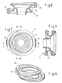
- Figur 7
- eine Abbildung des in dem Ringnutverteilerblock ausgebildeten Schmelzekörpers,
- Figur 8
- einen Schnitt durch den in Figur 7 dargestellten Schmelzekörper entlang der Linie VIII-VIII,
- Figur 9
- einen Schnitt durch den Schmelzekörper entlang der Linie IX-IX in Figur 7 und
- Figur 10
- eine perspektivische Ansicht des Schmelzekörpers.
- 1
- Extrusionskopf
- 2
- Pinole
- 3
- Bohrung
- 4
- Ringnutverteilerblock
- 5
- Verteilerscheiben
- 6
- erster Ringverteilerkanal
- 7
- zweiter Ringverteilerkanal
- 8
- erster Zufuhrkanal
- 9
- zweiter Zufuhrkanal
- 10
- erster Extruder
- 11
- zweiter Extruder
- 12
- erster Zulaufspalt
- 13
- zweiter Zulaufspalt
- 14
- Ringraum
- 15
- Ringspaltdüse
- 16
- Vorformling
- 17
- Schmelzekörper
- 18
- Angussstellen
- 19
- erster Abschnitt des Zulaufspalts
- 20
- zweiter Abschnitt des Zulaufspalts
Claims (10)
- Extrusionskopf zur Herstellung von schlauch- oder rohrförmigen Vorformlingen aus thermoplastischem Kunststoff, als Radialangusskopf mit wenigstens einer zentralen Bohrung, wenigstens einer in der Bohrung angeordneten Pinole, die in der Bohrung einen Ringraum als Fließweg für das zu extrudierende Material begrenzt, mit wenigstens einem Ringverteilerkanal, der den Ringraum umgibt und über wenigstens einen Zufuhrkanal an einen Extruder anschließbar ist, wobei der Ringverteilerkanal über einen ringförmigen Zulaufspalt an den die Pinole umgebenden Ringraum angeschlossen ist und wobei der Querschnitt des Ringverteilerkanals von der Mündung des Zufuhrkanals in Strömungsrichtung betrachtet kontinuierlich abnimmt, dadurch gekennzeichnet, dass der Strömungswiderstand des Zulaufspalts (11, 12) in Strömungsrichtung des Materials von der Mündung des Zufuhrkanals (8, 9) ausgehend kontinuierlich abnimmt.
- Extrusionskopf nach Anspruch 1, dadurch gekennzeichnet, dass der Strömungswiderstand des Zulaufspalts (12, 13) und der Querschnitt des Ringverteilerkanals (8, 9) so aufeinander abgestimmt sind, dass die Summen der Strömungswiderstände jeweils des Ringverteilerkanals (6, 7) und des Zulaufspalts (12, 13) in jeder Winkellage in Umfangsrichtung etwa gleich groß sind.
- Extrusionskopf nach einem der Ansprüche 1 oder 2, dadurch gekennzeichnet, dass die Länge des Zulaufspalts (12, 13) in Strömungsrichtung in Abhängigkeit vom Querschnitt des Ringverteilerkanals (6, 7) in Strömungsrichtung abnimmt.
- Extrusionskopf nach Anspruch 3, dadurch gekennzeichnet, dass die Länge des Zulaufspalts (12, 13) in Strömungsrichtung über einen Winkelumfang von je 180° von der Mündung des Zufuhrkanals (8, 9) ausgehend abnimmt.
- Extrusionskopf nach Anspruch 1, dadurch gekennzeichnet, dass die Weite des Zulaufspalts (12, 13) in Strömungsrichtung in Abhängigkeit vom Querschnitt des Ringverteilerkanals (6, 7) zunimmt.
- Extrusionskopf nach einem der Ansprüche 1 bis 5, dadurch gekennzeichnet, dass wenigstens zwei übereinander angeordnete Ringverteilerkanäle (6, 7) zur Koextrusion eines mehrschichtigen Vorformlings vorgesehen sind, wobei ein erster Ringverteilerkanal (6) über einen ersten umlaufenden Zulaufspalt (12) und ein zweiter Ringverteilerkanal (7) über einen zweiten umlaufenden Zulaufspalt (13) in den Ringraum (14) münden.
- Extrusionskopf nach Anspruch 6, dadurch gekennzeichnet, dass auf den Umfang des Ringraums (14) bezogen die Ringverteilerkanäle (6, 7) an diametral gegenüberliegenden Stellen an jeweils einen Zufuhrkanal (8, 9) angeschlossen sind.
- Vorrichtung nach einem der Ansprüche 1 bis 7, dadurch gekennzeichnet, dass der Zufuhrkanal (8, 9) im Bereich des größten Querschnitts des Ringverteilerkanals (6, 7) in diesen mündet und dass der Ringverteilerkanal (6, 7) diametral gegenüberliegend der Mündung des Zufuhrkanals (8, 9) seinen engsten Querschnitt aufweist.
- Vorrichtung nach einem der Ansprüche 1 bis 8, dadurch gekennzeichnet, dass der Zulaufspalt (12, 13) einen in Bezug auf die Mittellängsachse der Bohrung (3) sich in einer senkrechten Ebene erstreckenden, zumindest teilweise umlaufenden ersten Abschnitt (19) und einen hierzu konisch verlaufenden zweiten Abschnitt (20) aufweist.
- Vorrichtung nach Anspruch 9, dadurch gekennzeichnet, dass die Länge des ersten Abschnitts (19) von der Mündung des Zufuhrkanals (8, 9) ausgehend jeweils in Umfangsrichtung kontinuierlich abnimmt.
Priority Applications (1)
| Application Number | Priority Date | Filing Date | Title |
|---|---|---|---|
| EP03016061.8A EP1498254B1 (de) | 2003-07-15 | 2003-07-15 | Extrusionskopf |
Applications Claiming Priority (1)
| Application Number | Priority Date | Filing Date | Title |
|---|---|---|---|
| EP03016061.8A EP1498254B1 (de) | 2003-07-15 | 2003-07-15 | Extrusionskopf |
Publications (2)
| Publication Number | Publication Date |
|---|---|
| EP1498254A1 true EP1498254A1 (de) | 2005-01-19 |
| EP1498254B1 EP1498254B1 (de) | 2013-09-11 |
Family
ID=33462126
Family Applications (1)
| Application Number | Title | Priority Date | Filing Date |
|---|---|---|---|
| EP03016061.8A Expired - Lifetime EP1498254B1 (de) | 2003-07-15 | 2003-07-15 | Extrusionskopf |
Country Status (1)
| Country | Link |
|---|---|
| EP (1) | EP1498254B1 (de) |
Cited By (1)
| Publication number | Priority date | Publication date | Assignee | Title |
|---|---|---|---|---|
| CN111491774A (zh) * | 2017-11-07 | 2020-08-04 | W·米勒有限公司 | 用于由热塑性材料来生产管状坯料的挤出模具用的环形分配器 |
Families Citing this family (1)
| Publication number | Priority date | Publication date | Assignee | Title |
|---|---|---|---|---|
| DE102022104059B3 (de) * | 2022-02-21 | 2023-07-13 | BBM Maschinenbau und Vertriebs GmbH | Coextrusionswerkzeug zur Herstellung mehrschichtiger, schlauchartiger Vorformlinge aus thermoplastischem Kunststoff |
Citations (7)
| Publication number | Priority date | Publication date | Assignee | Title |
|---|---|---|---|---|
| US4395221A (en) | 1980-01-04 | 1983-07-26 | Mobil Oil Corporation | Tubular extrusion apparatus |
| DE19535749C1 (de) * | 1995-09-26 | 1996-12-19 | Mueller Kg W | Extrusionskopf zur Herstellung von schlauch- oder rohrförmigen Vorformlingen aus extrudierbarem Kunststoff |
| US5667818A (en) | 1993-11-05 | 1997-09-16 | Guillemette; A. Roger | Extrusion system with balanced flow passage |
| US5702664A (en) | 1995-10-06 | 1997-12-30 | The Japan Steel Works, Ltd. | Method of and apparatus for extrusion-molding a laminated parison, and a vessel produced from the laminated parison |
| US5779959A (en) | 1990-09-20 | 1998-07-14 | General Electric Company | Process for forming plastic articles |
| EP0876895A1 (de) | 1997-05-10 | 1998-11-11 | B & W Kunststoffmaschinenbau & Handelsgesellschaft mbH | Extrusionswerkzeug und Verfahren zu seiner Herstellung |
| EP1106327A1 (de) | 1999-12-10 | 2001-06-13 | Fischer-W. Müller Blasformtechnik GmbH | Extrusionskopf für das Blasformen von Hohlkörpern aus thermoplastischem Kunststoff |
-
2003
- 2003-07-15 EP EP03016061.8A patent/EP1498254B1/de not_active Expired - Lifetime
Patent Citations (7)
| Publication number | Priority date | Publication date | Assignee | Title |
|---|---|---|---|---|
| US4395221A (en) | 1980-01-04 | 1983-07-26 | Mobil Oil Corporation | Tubular extrusion apparatus |
| US5779959A (en) | 1990-09-20 | 1998-07-14 | General Electric Company | Process for forming plastic articles |
| US5667818A (en) | 1993-11-05 | 1997-09-16 | Guillemette; A. Roger | Extrusion system with balanced flow passage |
| DE19535749C1 (de) * | 1995-09-26 | 1996-12-19 | Mueller Kg W | Extrusionskopf zur Herstellung von schlauch- oder rohrförmigen Vorformlingen aus extrudierbarem Kunststoff |
| US5702664A (en) | 1995-10-06 | 1997-12-30 | The Japan Steel Works, Ltd. | Method of and apparatus for extrusion-molding a laminated parison, and a vessel produced from the laminated parison |
| EP0876895A1 (de) | 1997-05-10 | 1998-11-11 | B & W Kunststoffmaschinenbau & Handelsgesellschaft mbH | Extrusionswerkzeug und Verfahren zu seiner Herstellung |
| EP1106327A1 (de) | 1999-12-10 | 2001-06-13 | Fischer-W. Müller Blasformtechnik GmbH | Extrusionskopf für das Blasformen von Hohlkörpern aus thermoplastischem Kunststoff |
Cited By (1)
| Publication number | Priority date | Publication date | Assignee | Title |
|---|---|---|---|---|
| CN111491774A (zh) * | 2017-11-07 | 2020-08-04 | W·米勒有限公司 | 用于由热塑性材料来生产管状坯料的挤出模具用的环形分配器 |
Also Published As
| Publication number | Publication date |
|---|---|
| EP1498254B1 (de) | 2013-09-11 |
Similar Documents
| Publication | Publication Date | Title |
|---|---|---|
| EP1116569B1 (de) | Extruderdüsenkopf | |
| DE2537419C2 (de) | Schmelzeverteiler in Rohr- oder Blasköpfen mit einer Pinole als Kern und diese umgebenden Gehäuse | |
| DE69013496T2 (de) | Düse für ein mehrschichtiges Element mit verstellbaren Spalten. | |
| DE2510127C2 (de) | Strangpreßkopf zum Herstellen eines aus zwei konzentrischen, mit ihren Fließnähten versetzt zueinander angeordneten Schichten bestehenden Verbundschlauches aus thermoplastischem Kunststoff | |
| DE1276906B (de) | Spritzkopf | |
| DE2718537C3 (de) | Extrudiereinrichtung zum Herstellen eines aus wenigstens zwei Schichten bestehenden Verbundrohres aus thermoplastischen Kunsts | |
| DE69312074T2 (de) | Verteilerkopf zur herstellung von rohrförmigen profilen aus einem oder mehreren kunststoffsträngen | |
| DE19535749C1 (de) | Extrusionskopf zur Herstellung von schlauch- oder rohrförmigen Vorformlingen aus extrudierbarem Kunststoff | |
| DE3532996A1 (de) | Extrusionskopf | |
| EP1055504B1 (de) | Extruderdüsenkopf | |
| EP4010166B1 (de) | Schmelzeverteiler | |
| EP1784297B1 (de) | Folienblaskopf für die herstellung von schlauchfolien | |
| EP0923445B1 (de) | Fassartiger behälter aus kunststoff sowie verfahren und vorrichtung zu seiner herstellung | |
| DE19959482A1 (de) | Extrusionskopf für das Blasformen von Hohlkörpern aus thermoplastischem Kunststoff | |
| DE2911833C3 (de) | Gerader Spritzkopf zum Extrudieren zweier zueinander konzentrischer Kunststoffrohre | |
| EP1498254B1 (de) | Extrusionskopf | |
| EP1459866B1 (de) | Extrusionskopf sowie Extrusionsverfahren | |
| DE4109369A1 (de) | Werkzeugkopf zum strangpressen von schlauchfoermigen oder rohrfoermigen vorformlingen aus thermoplastifiziertem kunststoff | |
| DE102021118705A1 (de) | Vorrichtung und Verfahren für die biaxiale Kunststoff-Extrusion | |
| DE19720862C1 (de) | Extrusionswerkzeug und Verfahren zu seiner Herstellung | |
| EP2202046A1 (de) | Verfahren, Extrusionskopf und Vorrichtung für die Herstellung eines schlauchförmigen Formlings aus extrudierbarem Kunststoff | |
| DE19643224C1 (de) | Verteiler für einen Extrusionskopf zur Herstellung von schlauchförmigen Vorformlingen aus extrudierbarem Kunststoff | |
| EP0950500A1 (de) | Verfahren und Vorrichtung zur Herstellung mehrschichtiger Kunststoffrohre aus Polymermaterialien | |
| DE2554238A1 (de) | Werkzeug zum steglosen extrudieren von hohlprofilen | |
| EP0967065B1 (de) | Vorrichtung zum Herstellen konzentrischer Schmelzeströme |
Legal Events
| Date | Code | Title | Description |
|---|---|---|---|
| PUAI | Public reference made under article 153(3) epc to a published international application that has entered the european phase |
Free format text: ORIGINAL CODE: 0009012 |
|
| AK | Designated contracting states |
Kind code of ref document: A1 Designated state(s): AT BE BG CH CY CZ DE DK EE ES FI FR GB GR HU IE IT LI LU MC NL PT RO SE SI SK TR |
|
| AX | Request for extension of the european patent |
Extension state: AL LT LV MK |
|
| RAP1 | Party data changed (applicant data changed or rights of an application transferred) |
Owner name: KAUTEX MASCHINENBAU GMBH |
|
| 17P | Request for examination filed |
Effective date: 20050405 |
|
| AKX | Designation fees paid |
Designated state(s): AT BE BG CH CY CZ DE DK EE ES FI FR GB GR HU IE IT LI LU MC NL PT RO SE SI SK TR |
|
| 17Q | First examination report despatched |
Effective date: 20090415 |
|
| GRAP | Despatch of communication of intention to grant a patent |
Free format text: ORIGINAL CODE: EPIDOSNIGR1 |
|
| INTG | Intention to grant announced |
Effective date: 20130422 |
|
| GRAS | Grant fee paid |
Free format text: ORIGINAL CODE: EPIDOSNIGR3 |
|
| GRAA | (expected) grant |
Free format text: ORIGINAL CODE: 0009210 |
|
| AK | Designated contracting states |
Kind code of ref document: B1 Designated state(s): AT BE BG CH CY CZ DE DK EE ES FI FR GB GR HU IE IT LI LU MC NL PT RO SE SI SK TR |
|
| REG | Reference to a national code |
Ref country code: GB Ref legal event code: FG4D Free format text: NOT ENGLISH |
|
| REG | Reference to a national code |
Ref country code: CH Ref legal event code: EP |
|
| REG | Reference to a national code |
Ref country code: AT Ref legal event code: REF Ref document number: 631358 Country of ref document: AT Kind code of ref document: T Effective date: 20130915 |
|
| REG | Reference to a national code |
Ref country code: IE Ref legal event code: FG4D Free format text: LANGUAGE OF EP DOCUMENT: GERMAN |
|
| REG | Reference to a national code |
Ref country code: DE Ref legal event code: R096 Ref document number: 50314893 Country of ref document: DE Effective date: 20131031 |
|
| PG25 | Lapsed in a contracting state [announced via postgrant information from national office to epo] |
Ref country code: CY Free format text: LAPSE BECAUSE OF FAILURE TO SUBMIT A TRANSLATION OF THE DESCRIPTION OR TO PAY THE FEE WITHIN THE PRESCRIBED TIME-LIMIT Effective date: 20130703 Ref country code: SE Free format text: LAPSE BECAUSE OF FAILURE TO SUBMIT A TRANSLATION OF THE DESCRIPTION OR TO PAY THE FEE WITHIN THE PRESCRIBED TIME-LIMIT Effective date: 20130911 |
|
| REG | Reference to a national code |
Ref country code: NL Ref legal event code: VDEP Effective date: 20130911 |
|
| PG25 | Lapsed in a contracting state [announced via postgrant information from national office to epo] |
Ref country code: GR Free format text: LAPSE BECAUSE OF FAILURE TO SUBMIT A TRANSLATION OF THE DESCRIPTION OR TO PAY THE FEE WITHIN THE PRESCRIBED TIME-LIMIT Effective date: 20131212 Ref country code: SI Free format text: LAPSE BECAUSE OF FAILURE TO SUBMIT A TRANSLATION OF THE DESCRIPTION OR TO PAY THE FEE WITHIN THE PRESCRIBED TIME-LIMIT Effective date: 20130911 Ref country code: FI Free format text: LAPSE BECAUSE OF FAILURE TO SUBMIT A TRANSLATION OF THE DESCRIPTION OR TO PAY THE FEE WITHIN THE PRESCRIBED TIME-LIMIT Effective date: 20130911 |
|
| PG25 | Lapsed in a contracting state [announced via postgrant information from national office to epo] |
Ref country code: CY Free format text: LAPSE BECAUSE OF FAILURE TO SUBMIT A TRANSLATION OF THE DESCRIPTION OR TO PAY THE FEE WITHIN THE PRESCRIBED TIME-LIMIT Effective date: 20130911 |
|
| PG25 | Lapsed in a contracting state [announced via postgrant information from national office to epo] |
Ref country code: EE Free format text: LAPSE BECAUSE OF FAILURE TO SUBMIT A TRANSLATION OF THE DESCRIPTION OR TO PAY THE FEE WITHIN THE PRESCRIBED TIME-LIMIT Effective date: 20130911 Ref country code: NL Free format text: LAPSE BECAUSE OF FAILURE TO SUBMIT A TRANSLATION OF THE DESCRIPTION OR TO PAY THE FEE WITHIN THE PRESCRIBED TIME-LIMIT Effective date: 20130911 Ref country code: RO Free format text: LAPSE BECAUSE OF FAILURE TO SUBMIT A TRANSLATION OF THE DESCRIPTION OR TO PAY THE FEE WITHIN THE PRESCRIBED TIME-LIMIT Effective date: 20130911 Ref country code: CZ Free format text: LAPSE BECAUSE OF FAILURE TO SUBMIT A TRANSLATION OF THE DESCRIPTION OR TO PAY THE FEE WITHIN THE PRESCRIBED TIME-LIMIT Effective date: 20130911 Ref country code: SK Free format text: LAPSE BECAUSE OF FAILURE TO SUBMIT A TRANSLATION OF THE DESCRIPTION OR TO PAY THE FEE WITHIN THE PRESCRIBED TIME-LIMIT Effective date: 20130911 |
|
| PG25 | Lapsed in a contracting state [announced via postgrant information from national office to epo] |
Ref country code: ES Free format text: LAPSE BECAUSE OF FAILURE TO SUBMIT A TRANSLATION OF THE DESCRIPTION OR TO PAY THE FEE WITHIN THE PRESCRIBED TIME-LIMIT Effective date: 20130911 |
|
| REG | Reference to a national code |
Ref country code: DE Ref legal event code: R097 Ref document number: 50314893 Country of ref document: DE |
|
| REG | Reference to a national code |
Ref country code: DE Ref legal event code: R082 Ref document number: 50314893 Country of ref document: DE Representative=s name: KIERDORF RITSCHEL PATENTANWAELTE PARTG MBB, DE Ref country code: DE Ref legal event code: R082 Ref document number: 50314893 Country of ref document: DE Representative=s name: KIERDORF RITSCHEL RICHLY PATENTANWAELTE PARTG , DE Ref country code: DE Ref legal event code: R082 Ref document number: 50314893 Country of ref document: DE Representative=s name: RICHLY & RITSCHEL PATENTANWAELTE PARTG MBB, DE |
|
| PG25 | Lapsed in a contracting state [announced via postgrant information from national office to epo] |
Ref country code: PT Free format text: LAPSE BECAUSE OF FAILURE TO SUBMIT A TRANSLATION OF THE DESCRIPTION OR TO PAY THE FEE WITHIN THE PRESCRIBED TIME-LIMIT Effective date: 20140113 |
|
| PLBE | No opposition filed within time limit |
Free format text: ORIGINAL CODE: 0009261 |
|
| STAA | Information on the status of an ep patent application or granted ep patent |
Free format text: STATUS: NO OPPOSITION FILED WITHIN TIME LIMIT |
|
| 26N | No opposition filed |
Effective date: 20140612 |
|
| REG | Reference to a national code |
Ref country code: DE Ref legal event code: R097 Ref document number: 50314893 Country of ref document: DE Effective date: 20140612 |
|
| PG25 | Lapsed in a contracting state [announced via postgrant information from national office to epo] |
Ref country code: DK Free format text: LAPSE BECAUSE OF FAILURE TO SUBMIT A TRANSLATION OF THE DESCRIPTION OR TO PAY THE FEE WITHIN THE PRESCRIBED TIME-LIMIT Effective date: 20130911 |
|
| PG25 | Lapsed in a contracting state [announced via postgrant information from national office to epo] |
Ref country code: LU Free format text: LAPSE BECAUSE OF FAILURE TO SUBMIT A TRANSLATION OF THE DESCRIPTION OR TO PAY THE FEE WITHIN THE PRESCRIBED TIME-LIMIT Effective date: 20140715 |
|
| REG | Reference to a national code |
Ref country code: CH Ref legal event code: PL |
|
| GBPC | Gb: european patent ceased through non-payment of renewal fee |
Effective date: 20140715 |
|
| REG | Reference to a national code |
Ref country code: IE Ref legal event code: MM4A |
|
| REG | Reference to a national code |
Ref country code: FR Ref legal event code: ST Effective date: 20150331 |
|
| PG25 | Lapsed in a contracting state [announced via postgrant information from national office to epo] |
Ref country code: LI Free format text: LAPSE BECAUSE OF NON-PAYMENT OF DUE FEES Effective date: 20140731 Ref country code: CH Free format text: LAPSE BECAUSE OF NON-PAYMENT OF DUE FEES Effective date: 20140731 |
|
| PG25 | Lapsed in a contracting state [announced via postgrant information from national office to epo] |
Ref country code: FR Free format text: LAPSE BECAUSE OF NON-PAYMENT OF DUE FEES Effective date: 20140731 Ref country code: GB Free format text: LAPSE BECAUSE OF NON-PAYMENT OF DUE FEES Effective date: 20140715 |
|
| PG25 | Lapsed in a contracting state [announced via postgrant information from national office to epo] |
Ref country code: IE Free format text: LAPSE BECAUSE OF NON-PAYMENT OF DUE FEES Effective date: 20140715 |
|
| REG | Reference to a national code |
Ref country code: AT Ref legal event code: MM01 Ref document number: 631358 Country of ref document: AT Kind code of ref document: T Effective date: 20140715 |
|
| PG25 | Lapsed in a contracting state [announced via postgrant information from national office to epo] |
Ref country code: AT Free format text: LAPSE BECAUSE OF NON-PAYMENT OF DUE FEES Effective date: 20140715 |
|
| PG25 | Lapsed in a contracting state [announced via postgrant information from national office to epo] |
Ref country code: MC Free format text: LAPSE BECAUSE OF FAILURE TO SUBMIT A TRANSLATION OF THE DESCRIPTION OR TO PAY THE FEE WITHIN THE PRESCRIBED TIME-LIMIT Effective date: 20130911 |
|
| PG25 | Lapsed in a contracting state [announced via postgrant information from national office to epo] |
Ref country code: BG Free format text: LAPSE BECAUSE OF FAILURE TO SUBMIT A TRANSLATION OF THE DESCRIPTION OR TO PAY THE FEE WITHIN THE PRESCRIBED TIME-LIMIT Effective date: 20130911 |
|
| PG25 | Lapsed in a contracting state [announced via postgrant information from national office to epo] |
Ref country code: BE Free format text: LAPSE BECAUSE OF FAILURE TO SUBMIT A TRANSLATION OF THE DESCRIPTION OR TO PAY THE FEE WITHIN THE PRESCRIBED TIME-LIMIT Effective date: 20140731 Ref country code: HU Free format text: LAPSE BECAUSE OF FAILURE TO SUBMIT A TRANSLATION OF THE DESCRIPTION OR TO PAY THE FEE WITHIN THE PRESCRIBED TIME-LIMIT; INVALID AB INITIO Effective date: 20030715 Ref country code: TR Free format text: LAPSE BECAUSE OF FAILURE TO SUBMIT A TRANSLATION OF THE DESCRIPTION OR TO PAY THE FEE WITHIN THE PRESCRIBED TIME-LIMIT Effective date: 20130911 |
|
| PGFP | Annual fee paid to national office [announced via postgrant information from national office to epo] |
Ref country code: IT Payment date: 20180720 Year of fee payment: 16 Ref country code: DE Payment date: 20180725 Year of fee payment: 16 |
|
| REG | Reference to a national code |
Ref country code: DE Ref legal event code: R079 Ref document number: 50314893 Country of ref document: DE Free format text: PREVIOUS MAIN CLASS: B29C0047220000 Ipc: B29C0048325000 |
|
| REG | Reference to a national code |
Ref country code: DE Ref legal event code: R119 Ref document number: 50314893 Country of ref document: DE |
|
| PG25 | Lapsed in a contracting state [announced via postgrant information from national office to epo] |
Ref country code: DE Free format text: LAPSE BECAUSE OF NON-PAYMENT OF DUE FEES Effective date: 20200201 |
|
| PG25 | Lapsed in a contracting state [announced via postgrant information from national office to epo] |
Ref country code: IT Free format text: LAPSE BECAUSE OF NON-PAYMENT OF DUE FEES Effective date: 20190715 |