EP1498253A1 - Highly viscous molten coating composition coating core wire extrusion head - Google Patents
Highly viscous molten coating composition coating core wire extrusion head Download PDFInfo
- Publication number
- EP1498253A1 EP1498253A1 EP03703078A EP03703078A EP1498253A1 EP 1498253 A1 EP1498253 A1 EP 1498253A1 EP 03703078 A EP03703078 A EP 03703078A EP 03703078 A EP03703078 A EP 03703078A EP 1498253 A1 EP1498253 A1 EP 1498253A1
- Authority
- EP
- European Patent Office
- Prior art keywords
- core wire
- exit portion
- coating composition
- nipple
- coating
- Prior art date
- Legal status (The legal status is an assumption and is not a legal conclusion. Google has not performed a legal analysis and makes no representation as to the accuracy of the status listed.)
- Withdrawn
Links
Images


Classifications
-
- H—ELECTRICITY
- H01—ELECTRIC ELEMENTS
- H01B—CABLES; CONDUCTORS; INSULATORS; SELECTION OF MATERIALS FOR THEIR CONDUCTIVE, INSULATING OR DIELECTRIC PROPERTIES
- H01B13/00—Apparatus or processes specially adapted for manufacturing conductors or cables
- H01B13/06—Insulating conductors or cables
- H01B13/14—Insulating conductors or cables by extrusion
- H01B13/143—Insulating conductors or cables by extrusion with a special opening of the extrusion head
-
- B—PERFORMING OPERATIONS; TRANSPORTING
- B29—WORKING OF PLASTICS; WORKING OF SUBSTANCES IN A PLASTIC STATE IN GENERAL
- B29C—SHAPING OR JOINING OF PLASTICS; SHAPING OF MATERIAL IN A PLASTIC STATE, NOT OTHERWISE PROVIDED FOR; AFTER-TREATMENT OF THE SHAPED PRODUCTS, e.g. REPAIRING
- B29C48/00—Extrusion moulding, i.e. expressing the moulding material through a die or nozzle which imparts the desired form; Apparatus therefor
- B29C48/03—Extrusion moulding, i.e. expressing the moulding material through a die or nozzle which imparts the desired form; Apparatus therefor characterised by the shape of the extruded material at extrusion
- B29C48/06—Rod-shaped
-
- B—PERFORMING OPERATIONS; TRANSPORTING
- B29—WORKING OF PLASTICS; WORKING OF SUBSTANCES IN A PLASTIC STATE IN GENERAL
- B29C—SHAPING OR JOINING OF PLASTICS; SHAPING OF MATERIAL IN A PLASTIC STATE, NOT OTHERWISE PROVIDED FOR; AFTER-TREATMENT OF THE SHAPED PRODUCTS, e.g. REPAIRING
- B29C48/00—Extrusion moulding, i.e. expressing the moulding material through a die or nozzle which imparts the desired form; Apparatus therefor
- B29C48/25—Component parts, details or accessories; Auxiliary operations
- B29C48/30—Extrusion nozzles or dies
- B29C48/32—Extrusion nozzles or dies with annular openings, e.g. for forming tubular articles
- B29C48/335—Multiple annular extrusion nozzles in coaxial arrangement, e.g. for making multi-layered tubular articles
-
- B—PERFORMING OPERATIONS; TRANSPORTING
- B29—WORKING OF PLASTICS; WORKING OF SUBSTANCES IN A PLASTIC STATE IN GENERAL
- B29C—SHAPING OR JOINING OF PLASTICS; SHAPING OF MATERIAL IN A PLASTIC STATE, NOT OTHERWISE PROVIDED FOR; AFTER-TREATMENT OF THE SHAPED PRODUCTS, e.g. REPAIRING
- B29C48/00—Extrusion moulding, i.e. expressing the moulding material through a die or nozzle which imparts the desired form; Apparatus therefor
- B29C48/25—Component parts, details or accessories; Auxiliary operations
- B29C48/30—Extrusion nozzles or dies
- B29C48/32—Extrusion nozzles or dies with annular openings, e.g. for forming tubular articles
- B29C48/34—Cross-head annular extrusion nozzles, i.e. for simultaneously receiving moulding material and the preform to be coated
-
- B—PERFORMING OPERATIONS; TRANSPORTING
- B29—WORKING OF PLASTICS; WORKING OF SUBSTANCES IN A PLASTIC STATE IN GENERAL
- B29C—SHAPING OR JOINING OF PLASTICS; SHAPING OF MATERIAL IN A PLASTIC STATE, NOT OTHERWISE PROVIDED FOR; AFTER-TREATMENT OF THE SHAPED PRODUCTS, e.g. REPAIRING
- B29C48/00—Extrusion moulding, i.e. expressing the moulding material through a die or nozzle which imparts the desired form; Apparatus therefor
- B29C48/03—Extrusion moulding, i.e. expressing the moulding material through a die or nozzle which imparts the desired form; Apparatus therefor characterised by the shape of the extruded material at extrusion
- B29C48/09—Articles with cross-sections having partially or fully enclosed cavities, e.g. pipes or channels
-
- B—PERFORMING OPERATIONS; TRANSPORTING
- B29—WORKING OF PLASTICS; WORKING OF SUBSTANCES IN A PLASTIC STATE IN GENERAL
- B29C—SHAPING OR JOINING OF PLASTICS; SHAPING OF MATERIAL IN A PLASTIC STATE, NOT OTHERWISE PROVIDED FOR; AFTER-TREATMENT OF THE SHAPED PRODUCTS, e.g. REPAIRING
- B29C48/00—Extrusion moulding, i.e. expressing the moulding material through a die or nozzle which imparts the desired form; Apparatus therefor
- B29C48/15—Extrusion moulding, i.e. expressing the moulding material through a die or nozzle which imparts the desired form; Apparatus therefor incorporating preformed parts or layers, e.g. extrusion moulding around inserts
- B29C48/154—Coating solid articles, i.e. non-hollow articles
-
- B—PERFORMING OPERATIONS; TRANSPORTING
- B29—WORKING OF PLASTICS; WORKING OF SUBSTANCES IN A PLASTIC STATE IN GENERAL
- B29C—SHAPING OR JOINING OF PLASTICS; SHAPING OF MATERIAL IN A PLASTIC STATE, NOT OTHERWISE PROVIDED FOR; AFTER-TREATMENT OF THE SHAPED PRODUCTS, e.g. REPAIRING
- B29C48/00—Extrusion moulding, i.e. expressing the moulding material through a die or nozzle which imparts the desired form; Apparatus therefor
- B29C48/16—Articles comprising two or more components, e.g. co-extruded layers
- B29C48/18—Articles comprising two or more components, e.g. co-extruded layers the components being layers
- B29C48/21—Articles comprising two or more components, e.g. co-extruded layers the components being layers the layers being joined at their surfaces
-
- B—PERFORMING OPERATIONS; TRANSPORTING
- B29—WORKING OF PLASTICS; WORKING OF SUBSTANCES IN A PLASTIC STATE IN GENERAL
- B29L—INDEXING SCHEME ASSOCIATED WITH SUBCLASS B29C, RELATING TO PARTICULAR ARTICLES
- B29L2031/00—Other particular articles
- B29L2031/34—Electrical apparatus, e.g. sparking plugs or parts thereof
- B29L2031/3462—Cables
-
- Y—GENERAL TAGGING OF NEW TECHNOLOGICAL DEVELOPMENTS; GENERAL TAGGING OF CROSS-SECTIONAL TECHNOLOGIES SPANNING OVER SEVERAL SECTIONS OF THE IPC; TECHNICAL SUBJECTS COVERED BY FORMER USPC CROSS-REFERENCE ART COLLECTIONS [XRACs] AND DIGESTS
- Y10—TECHNICAL SUBJECTS COVERED BY FORMER USPC
- Y10S—TECHNICAL SUBJECTS COVERED BY FORMER USPC CROSS-REFERENCE ART COLLECTIONS [XRACs] AND DIGESTS
- Y10S118/00—Coating apparatus
- Y10S118/18—Wire and cord die
Definitions
- the present invention relates to wire coating extrusion and, more particularly, an extrusion head for a core wire coated with a high viscous melt-coating composition, which is constructed by extruding the high viscous material such as piezoelectric material round the core wire.
- a piezoelectric material is such a material that generates a voltage when a vibration is applied, and the piezoelectric ceramic and the polymer piezoelectric material are well known.
- the ceramic made of lead titanate zirconate, or the like is present as the former, and the monoaxial stretching polyvinylidene fluoride (PVDF), or the like is present as the latter.
- PVDF monoaxial stretching polyvinylidene fluoride
- the cord-like pressure- sensitive sensor is known. This cord-like pressure- sensitive sensor is a soft, long and narrow cord having a diameter of about 2.5 mm.
- This sensor is built around the power window of the car to prevent the accident, or built on the outer periphery of the automatic guided vehicle that runs about in the factory, the warehouse, or the hospital, otherwise this sensor is built on the fence, which is put around the site boundary, to sense the burglary.
- This sensor is convenient because such sensor can output a pressure change at the concerned portion as an electric signal, no matter which portion of this long and narrow cord is folded or no matter which portion of this cord is lightly touched by the foreign matter.
- FIG.4 A structure of the cord-like pressure-sensitive sensor using the coated core wire as an object of the present invention is shown in Fig.4.
- Fig.4 40 is a cord-like pressure-sensitive sensor.
- This sensor is constructed by coating a piezoelectric material 42 on a core wire (core electrode) 41 that extends in the axial direction, then winding a shield electrode 43 round the piezoelectric material 42, and then coating the outermost periphery with PVC (polyvinyl chloride resin) 44.
- PVC polyvinyl chloride resin
- the cord-like pressure-sensitive sensor 40 employs a resin material having a heat resistance, which permits the use up to the operating temperature of 120°C, as a composite piezoelectric material.
- this sensor can be used in a higher temperature range (120°C or less) than 90°C that is the highest operating temperature of the polymer piezoelectric material (monoaxial stretching polyvinylidene fluoride) or the composite piezoelectric material (composite piezoelectric material consisting of chloroprene and piezoelectric ceramic powders), which are typical in the conventional art.
- the composite piezoelectric material consists.of the resin having the flexibility and the piezoelectric ceramic, and also the flexible electrode consisting of the coil-like metal core electrode and the film-like outer electrode is employed.
- this sensor has the flexibility equivalent to the normal vinyl cord.
- the cord-like pressure-sensitive sensor 40 has a high sensitivity equivalent to the polymer piezoelectric material, and particularly has the high sensitivity equivalent to the polymer piezoelectric material in a low frequency range (10 Hz or less) in which the catch of the human body is sensed. This is because the relative dielectric constant (about 55) of this composite piezoelectric material is larger than the polymer piezoelectric material (about 10) and thus reduction in the sensitivity in the low frequency range (10 Hz or less) is small.
- the high heat-resistant composite piezoelectric material (piezoelectric material consisting of two different materials) is formed of the composite material that consists of the resin material and the piezoelectric ceramic powders whose size is 10 ⁇ m or less.
- the vibration sensing characteristic is implemented by the ceramic, and also the flexibility is implemented by the resin. Since noncrystalline polyethylene resin (molecular weight about 300,000) and noncrystalline polyethylene resin (molecular weight about 100,000) are compounded as the resin material, this composite piezoelectric material makes it possible to attain not only the high heat-resistance (120°C) and the flexibility, which brings about the easy formation, but also simple manufacturing steps in which the bridging is not required.
- the cord-like pressure-sensitive sensor 40 obtained in this manner does not have piezoelectric performance just after the piezoelectric material is molded. Therefore, the process of providing the piezoelectric performance to the piezoelectric material (polarizing process) must be executed by applying a DC high voltage of several kV/mm to the piezoelectric material. This polarizing process is executed by applying the DC high voltage to both electrodes after electrodes are formed on both sides of the composite piezoelectric material. If a minute defect such as a crack, or the like is present in the composite piezoelectric material, the short-circuit between both electrodes is ready to occur due to the discharge caused at the defect portion, so that the sufficient polarization voltage cannot be applied to the composite piezoelectric material.
- the defect can be sensed/avoided to stabilize the polarization, whereby the longer cord having a length of several tens meter can be attained.
- the coil-like metal core electrode is employed as the inner electrode and the film-like electrode (triple-layered laminate film consisting of aluminum-polyethylene terephthalate-aluminum) is employed as the outer electrode.
- the film-like electrode striple-layered laminate film consisting of aluminum-polyethylene terephthalate-aluminum
- the core electrode is made of the copper-silver alloy coil
- the outer electrode is made of the triple-layered laminate film consisting of aluminum-polyethylene terephthalate-aluminum
- the piezoelectric material is made of the polyethylene resin+the piezoelectric ceramic powders
- the housing is made of the thermoplastic plastic.
- the relative dielectric constant is 55
- an amount of generated charge is 10-13 C(coulomb)/gf
- the maximum operating temperature is 120°C.
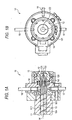
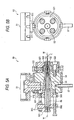
- Figs.5A and 5B show an extrusion head of this type in the conventional art, wherein Fig.5A is a longitudinal sectional view and Fig.5B is a side view.
- 50 is an extrusion head
- 51 is a melt-coating composition pressure-feeding portion
- 511 is a land portion
- 512 is a cap nut
- 52 is a die ring
- 521 is a die holding ring
- 522 is a thickness deviation adjusting bolt
- 523 is a tap bolt
- 53 is a nipple
- 54 is a die block
- 55 is a mandrel
- 56 is a nipple holder
- 561 is a wire guide
- 562 is a thickness deviation adjusting ring
- 563 is a gap adjusting nut
- 57 is a composition temperature sensor.
- the core wire W is guided linearly from the wire guide 561 on the left side in Fig.5A, then is moved linearly through passages in the mandrel 55 and the nipple 53 from there to the right side in Fig.5A, and then is pulled out from an exit portion of the die ring 52.
- the composite piezoelectric material consisting of the piezoelectric ceramic powders and the synthetic rubber is supplied from the melt-coating composition pressure-feeding portion 51 shown at the top in Fig. 5A and is heated by a heating apparatus (not shown). Then, such material is fed through a passage of the land portion 511 and a passage (not shown) of the mandrel 55 and a clearance 541, which is formed between an inner surface of the die block 54 and outer surfaces of the nipple 53 and the nipple holder 56, by a pressure-feeding mechanism (not shown) such as a screw, or the like in the melted state. Then, such material is output from an exit portion of the die ring 52 while coating round the outer side of the core wire W at the front end of the nipple 53.
- the internal shape of the die ring 52 in the apparatus in the conventional art is shaped into a taper (funnel) shape that an inner diameter is narrowed with the progress in the proceeding direction to prevent the stagnation of the melt-coating composition. It is considered that, because of this funnel shape, the melt-coating composition can be pressure-fed smoothly without the stagnation in the hollow portion. Therefore, this funnel shape is assumed as the best shape up to now and thus other shapes except this shape are not suitable for the pressure-feeding of high viscous composition.
- this melt-coating composition is formed of not the high viscous composition but the low viscous composition or the fluid liquid, the internal shape of the die ring should not always be shaped into the taper shape and thus such melt-coating composition can be pressure-fed smoothly even when the internal shape of the die ring is shaped into the perpendicular wall, e.g., a syringe, to the proceeding direction.
- this taper shape is an indispensable major premise in the extruding apparatus that extrudes the high viscous (so-called hard) composition such as the material of the pressure-sensitive sensor, and this shape is a ultimate shape.
- the existing state is that other shapes except the taper shape are not taken into consideration at all in this technical field.
- the coated core wire can be manufactured at a production speed of 1 m/min because the internal shape of the die ring is shaped into the taper shape.
- the production speed of 1 m/min is the upper limit, and leakage of the composition from the packing or breakage of the bolt is caused if the production speed is increased further more.
- the present invention has been made to overcome these problems, and it is an object of the present invention to provided a cord-like coated core wire extruding apparatus that can be driven at a high speed not to cause leakage of the melt coating composition from a packing and breakage of the bolt.
- an extrusion head of the present invention provides an extrusion head that comprises a die ring having an exit portion and a nipple arranged in vicinity of the exit portion, whereby a core wire passage is provided to an inside of the nipple in an axial direction, and a high viscous melt-coating composition is pressure-fed into a space, which is formed by the die ring and the nipple, toward the exit portion while drawing out a core wire from the core wire passage to the exit portion, and thus a cord-like coated core wire is extruded from the exit portion of the die ring while coating the core wire with the high viscous melt- coating composition, wherein a stagnation reservoir in which the high viscous melt-coating composition is stagnated is constructed in a space that is formed by the die ring and the nipple in vicinity of the exit portion.
- melt-coating composition has the high viscosity
- such composition can fed to the exit portion without the large surface frictional resistance, and thus the high-speed production can be achieved.
- the stagnation reservoir is constructed by forming a wall surface having the exit portion into a shape that is perpendicular or almost perpendicular to a proceeding direction of the core wire at the exit portion. According to the above structure, the stagnation reservoir having the simplest structure can be obtained.
- the stagnation reservoir is constructed by forming a wall surface having the exit portion into stepwise shapes on an oblique surface that becomes narrow along a proceeding direction of the core wire at the exit portion. According to the above structure, since the stagnation reservoir can be formed more quickly than the stagnation reservoir set forth in claim 3, the start of the operation is accelerated and thus the apparatus can be shifted quickly to the steady operation.
- the high viscous melt-coating composition is supplied to the die ring via a linear path. According to the above structure, the frictional resistance can be reduced rather than the conventional apparatus that supplies the melt-coating composition perpendicularly, and thus the production speed can be largely increased.
- a core wire passage in a nipple holder that fixes the nipple is formed as a linear path. According to the above structure, since the core wire can be arranged not to interference with the extruding apparatus and also the folded portion is eliminated from the core wire, the coating extrusion can be carried out without application of the unnecessary load.
- a core wire passage in a nipple holder that fixes the nipple is formed as a path that is perpendicular or oblique to the core wire passage in the nipple.
- the wire coating extruding apparatus has such a structure that a flow of the melt- coating composition is supplied via a linear path until the melt-coating composition is coated on the core wire, a flow direction of the melt-coating composition is never bent and also the coating extrusion can be carried out while suppressing increase of the extrusion pressure.
- the coating extrusion of the core wire can be achieved successively by employing the screw-type extruder.
- Figs.1A and 1B show an extrusion head according to a first embodiment of the present invention, wherein Fig.1A is a front sectional view and Fig.1B is a side sectional view.
- 10 is an extrusion head according to the first embodiment of the present invention, and a melt-coating composition pressure-feeding portion 11 on the left side in Fig.1A and a die ring 12 on the right side in Fig.1A are fixed to a die block 14 as a base, which has a through hole 141 in the longitudinal direction in Fig.1A, via fixing members respectively.
- the melt-coating composition pressure-feeding portion 11 is a tubular body in which a cylindrical space 111 is formed in the longitudinal direction, and is communicated with a through hole 141 of the die block 14 at the front end (the right side in Fig.1A) in the proceeding direction.
- a uniaxial screw 16 that is used commonly as a nipple holder is inserted into this cylindrical space 111.
- a nipple 13 is fixed to the front end of the uniaxial screw 16 in the proceeding direction, and spiral vanes 164 are formed on the surface thereof.
- the melt-coating composition that is present in the cylindrical space 111 is fed forward (fed to the right side in Fig. 1A) by the revolution of the uniaxial screw 16.
- a core wire passage 161 through which the core wire W is fed in its longitudinal direction is formed in the inside of the uniaxial screw 16.
- An outer shape of the front end of the nipple 13, which is fixed to the front end of the uniaxial screw 16 in the proceeding direction, has a circular cone shape, and also an outer shape of the rear' end thereof has a cylindrical shape.
- a core wire passage 131 through which the core wire W is fed in its longitudinal direction is formed in the inside of the nipple 13, and is communicated with the core wire passage 161.
- the die ring 12 is formed as a cap-like shape that has a concave space 121 in its inside, and an exit portion 122 that is communicatedwith the concave space 121 and the outside is opened at the center in the axial direction.
- This exit portion 122 is arrange near the front end of the core wire passage 131 of the nipple 13.
- a pressure sensor 18 and a resin temperature sensor 17 are fitted from top and bottom sides of the die block 14 toward the center to sense the pressure and the temperature of the melt-coating composition in the through hole 141 respectively.
- the core wire is guided to the core wire passage 161, which is formed in the inside of the uniaxial screw 16, from the left side in Fig.1A to move linearly in the core wire passage 161, then is fed through the core wire passage 131 of the nipple 13 to output from the opening portion of the nipple 13, and then is fed through the concave space 121 in the inside of the die ring 12 to output from the exit portion 122 of the die ring 12.
- the moving core wire W can be arranged without interference with the extruding apparatus. Also, since the folded portion can be eliminated from the core wire W, the coating extrusion can be carried out without application of the unnecessary load.
- the high viscous coating composition (the composite piezoelectric material consisting of the piezoelectric ceramic powders and the synthetic rubber) is fed into the cylindrical space 111 on the outside of the uniaxial screw 16 from the left side in Fig.1A in its melt state that is obtained by heating such composition close to 100 °C by means of a heater heating apparatus (not shown). Because the uniaxial screw 16 is rotated in the cylindrical space 111, such coating composition is pressure-fed to the front side (right side) by the spiral vanes 164 formed on the surface of the uniaxial screw 16 and finally reaches the concave space 121 in the inside of the die ring 12.
- respective embodiments are characterized in that the wall surface containing the exit portion 122 of the die ring 12 is formed perpendicularly to the proceeding direction of the core wire W at the exit portion 122.
- a difference resides in that, in the apparatus in the prior art, the internal shape of the die ring 52 is shaped into the funnel shape that is narrowed with the proceed along the proceeding direction not to stagnate the melt-coating composition whereas, in the present invention, the internal shape of the die ring 12 is shaped to stagnate positively the melt-coating composition.
- the wall surface containing the exit portion 122 is formed perpendicularly in this manner, the high viscous melt-coating composition that enters into the corner portion is brought into the state that such composition just enters into the "stagnation reservoir" in which such composition can move neither forward nor back.
- the applicant's present understanding it is supposed that, if the internal shape of the die ring is shaped into the funnel shape, most part of the high viscous melt-coating composition that is to be fed toward the exit portion 122 is moved while contacting to the funnel surface, and thus the frictional resistance on the surface becomes large and the movement of such composition becomes slow.
- the high viscous melt-coating composition that is to be fed toward the exit portion 122 does not contact to such wall surface but is moved while contacting to the same composition that still stagnates in the stagnation reservoir, and thus the friction is not so large and the high-speed movement of such composition can be attained.
- Figs. 3A to 3E show various structures of the stagnation reservoir formed in the die ring 32.
- Figs.3A to 3C show a pot type, wherein Fig.3A is a right-angle type, Fig.3B is a curved type, and Fig.3C is an obtuse-angle type.
- Figs.3D and 3E show a colosseum (circular stadium) type, wherein Fig.3D is a right-angle type and Fig.3E is a curved type.
- the high viscous melt-coating composition that is pressure-fed along the direction indicated by an arrow is not directed to the stagnation reservoir but such composition is moved toward the exit portion while contacting to the same composition being stagnated in the stagnation reservoir, and thus the high-speed movement of such composition can be achieved.
- Fig.2 shows a nipple portion of an extrusion head according to a second embodiment of the present invention.
- Fig.2A is a A-A sectional view in Fig.2B
- Fig.2B is a side view
- Fig.2C is a B-B sectional view in Fig.2A
- Fig.2D is a plan view.
- Fig.2A 24 is a tubular die block that has a through hole 241 formed to pass through in the longitudinal direction.
- a die ring 22 is fixed to the right side of the die block 24, and the same uniaxial screw as explained in Fig.1, although not shown, is positioned on the left side of the die block 24.
- the melt-coating composition is pressure-fed by the rotation of the screw.
- a coupling portion 242 that passes through the center of the pipe to couple the walls of the pipes is provided near the center of the through hole 241 in the longitudinal direction.
- a nipple 23 is fixed to the right side of the coupling portion 242, and the left side of the coupling portion 242 is closed by a tap 26.
- a width of the coupling portion 242 in the radial direction is formed narrowly. Therefore, since the through hole 241 has passages (241a, 241b in Fig.2C) on both sides of the coupling portion 242, a passage 241c as a space to which the melt-coating composition comes up in Fig.2A and a passage 241d as a space on the die ring side (both passages are present on the front side and the back side of this sheet in a bypath diagram 2C of the coupling portion 242) are communicated with each other. Thus, the melt-coating composition that reaches the left side of the die block 24 can be moved to the die ring 22 side.
- the nipple 23 has a through hole 231 that passes through the center in the axial direction, and a hole provided in the radial direction to communicate with the through hole 231.
- a die block passage 243 that is communicated with the outside of the die block and the radial hole in the nipple 23 is provided to the coupling portion 242 of the die block 24.
- the core wire W is supplied to the through hole 231 of the nipple 23 from the outside via the die block passage 243 and the radial hole of the nipple 23, and then is output to the outside of the die ring 22 via an exit portion 222 of the die ring 22.
- a feature of the second embodiment of the present invention is that the core wire W is supplied perpendicularly to the nipple 23.
- the sensor having the same advantages can be manufactured without complicated workings by which the core wire passage 161 (Fig.1) is formed in the inside of the uniaxial screw 16.
- the core wire W is supplied perpendicularly to the nipple 23 herein. But it is a matter of course that the core wire W may be supplied obliquely to the nipple 23.
- the high viscous melt-coating composition is pressure-fed linearly, and also the stagnation reservoir is formed.
- the linear pressure-feeding of the high viscous melt-coating composition is not implemented by the apparatus in the prior art. According to the present invention, since the high viscous melt-coating composition is pressure-fed linearly, the frictional resistance can be reduced and thus the high-speed pressure-feeding of such composition can be attained.
- the stagnation reservoir is formed as follows.
- the die ring 22 has a cap shape, and the exit portion 222 that is communicated with the outside is opened in a cap outer wall 221. Because the cap outer wall 221 having the exit portion 222 of the die ring 22 is formed perpendicularly to the proceeding direction of the core wire W at the exit portion 222, the stagnation reservoir is formed at the corner portion.
- this exit portion 222 is formed in vicinity of the top end of the through hole 231 of the nipple 23.
- the pressure sensor and the resin temperature sensor are fitted to direct from the top and the bottom of the die block 24 to the center respectively to sense the pressure and the temperature of the melt-coating composition in the through hole 241.
- the core wire W is supplied to the through hole 231 of the nipple from the passage 243 of the die block 24, and then is output to the outside of the die ring 22 via the exit portion 222 of the die ring 22. Meanwhile, the melt-coating composition is pressure-fed to the left side space 241c in the die block 24 in the melted state in which such composition is heated up to almost 100 °C by a heater heating apparatus (not shown), and then comes finally up to the right side space 241d in the die ring 12 via the bypaths 241a, 241b (Fig.2C). Then, the cord-like coated wire having the core wire at its center is output from the exit portion 222 while coating the core wire W, which is fed from the nipple 23, with the composition in the right side space 241d in the die ring 12.
- the stagnation reservoir is formed at the corner portion because the wall portion of the die ring is formed perpendicularly to the proceeding direction of the core wire W. Therefore, since the composition that enters once into the corner portion can move neither forward nor backward, the high viscous melt-coating composition being pressure-fed cannot go to the stagnation reservoir and thus such composition moves toward the exit portion at a high speed while lightly contacting to the same composition being stagnated in the stagnation reservoir.
- the production speed according to the second embodiment of the present invention becomes 5 m/min to 12 m/min, and thus the speed-up can be largely achieved in contrast to the apparatus in the prior art.
- an extruding apparatus that comprises a die ring having an exit portion and a nipple arranged in vicinity of the exit portion, whereby a core wire passage is provided to an inside of the nipple in an axial direction, and a high viscous melt-coating composition is pressure-fed into a space, which is formed by the die ring and the nipple, toward the exit portion while drawing out a core wire from the core wire passage to the exit portion, and thus a cord-like coated core wire is extruded from the exit portion of the die ring while coating the core wire with the high viscous melt-coating composition, wherein a stagnation reservoir in which the high viscous melt-coating composition is stagnated is constructed in a space that is formed by the die ring and the nipple in vicinity of the exit portion. Therefore, even though the melt-coating composition has the high viscosity, such composition can fed to the exit portion without the large surface frictional resistance.
- the high viscous melt-coating composition is supplied to the die ring via the linear paths. Therefore, the frictional resistance can be reduced rather than the conventional apparatus that supplies the melt-coating composition perpendicularly, and thus the production speed can be largely increased.
Landscapes
- Engineering & Computer Science (AREA)
- Manufacturing & Machinery (AREA)
- Mechanical Engineering (AREA)
- Extrusion Moulding Of Plastics Or The Like (AREA)
- Coating Apparatus (AREA)
Abstract
Description
Claims (16)
- An extruding apparatus comprising:wherein the exit portion has a stagnation reservoir in which a melted high viscous composition is stagnated.a pressure-feeding portion for melting and pressure-feeding a high viscous composition; andan extrusion head for extruding the melted high viscous composition being fed from the pressure-feeding portion from an exit portion to shape into a predetermined shape,
- An extruding apparatus according to claim 1, wherein the stagnation reservoir is constructed by forming a wall surface having the exit portion into a shape that is perpendicular or almost perpendicular to a proceeding direction of the high viscous composition at the exit portion.
- An extruding apparatus according to claim 1, wherein the stagnation reservoir is constructed by forming a wall surface having the exit portion into stepwise shapes on an oblique surface that becomes narrow along a proceeding direction of the core wire at the exit portion.
- An extruding apparatus according to any one of claims 1 to 3, wherein the high viscous composition is supplied to a die ring via a linear path.
- An extrusion head comprising: a die ring having an exit portion and a nipple arranged in vicinity of the exit portion, whereby a core wire passage is provided to an inside of the nipple in an axial direction, and a high viscous melt-coating composition is pressure-fed into a space, which is formed by the die ring and the nipple, toward the exit portion while drawing out a core wire from the core wire passage to the exit portion, and thus a cord-like coated core wire is extruded from the exit portion of the die ring while coating the core wire with the high viscous melt- coating composition,
wherein a stagnation reservoir in which the high viscous melt-coating composition is stagnated is constructed in a space that is formed by the die ring and the nipple in vicinity of the exit portion. - An extrusion head according to claim 5, wherein the stagnation reservoir is constructed by forming a wall surface having the exit portion into a shape that is perpendicular or almost perpendicular to a proceeding direction of the core wire at the exit portion.
- An extrusion head according to claim 5, wherein the stagnation reservoir is constructed by forming a wall surface having the exit portion into stepwise shapes on an oblique surface that becomes narrow along a proceeding direction of the core wire at the exit portion.
- An extrusion head according to any one of claims 5 to 7, wherein the high viscous melt-coating composition is supplied to the die ring via a linear path.
- An extrusion head according to any one of claims 5 to 7, wherein a core wire passage in a nipple holder that fixes the nipple is formed as a linear path.
- An extrusion head according to any one of claims 5 to 7, wherein a core wire passage in a nipple holder that fixes the nipple is formed as a path that is perpendicular or oblique to the core wire passage in the nipple.
- A wire coating extruding apparatus comprising:wherein a flow of the melt-coating composition is supplied via a linear path until the melt-coating composition is coated on the core wire.an extruder for melting and extruding a coating composition; andan extrusion head for coating a core wire with a melt-coating composition;
- A wire coating extruding apparatus according to claim 11, wherein the extruder is a screw-type extruder.
- A wire coating extruding apparatus according to claim 11 or 12, wherein a mechanism for turning a direction of the core wire from a straight line is provided in the extrusion head.
- A wire coating extruding apparatus according to claim 12, wherein a through hole is provided in a screw of the extruder in a rotation shaft direction, and the core wire is passed through the through hole to apply a coating.
- A wire coating extruding apparatus according to claim 11 or 12, wherein a shape of an end surface of the exit portion of the extrusion head is formed like a circular cylinder.
- A wire coating extruding apparatus according to claim 11 or 12, wherein a shape of an end surface of the exit portion of the extrusion head has an opening angle by which the coating composition is not moved from the end surface except the exit portion at a time of extrusion.
Applications Claiming Priority (5)
| Application Number | Priority Date | Filing Date | Title |
|---|---|---|---|
| JP2002019672 | 2002-01-29 | ||
| JP2002019672A JP3546875B2 (en) | 2002-01-29 | 2002-01-29 | Wire coating extrusion equipment |
| JP2002067104 | 2002-03-12 | ||
| JP2002067104A JP3787772B2 (en) | 2002-03-12 | 2002-03-12 | High viscosity melt coating composition coated core wire extrusion head |
| PCT/JP2003/000849 WO2003064136A1 (en) | 2002-01-29 | 2003-01-29 | Highly viscous molten coating composition coating core wire extrusion head |
Publications (2)
| Publication Number | Publication Date |
|---|---|
| EP1498253A1 true EP1498253A1 (en) | 2005-01-19 |
| EP1498253A4 EP1498253A4 (en) | 2009-08-26 |
Family
ID=27667435
Family Applications (1)
| Application Number | Title | Priority Date | Filing Date |
|---|---|---|---|
| EP03703078A Withdrawn EP1498253A4 (en) | 2002-01-29 | 2003-01-29 | EXTRUDER HEAD WITH COATING WAVE THREAD FOR HIGH VISCOSITY FUSED COATING COMPOSITION |
Country Status (6)
| Country | Link |
|---|---|
| US (1) | US7323055B2 (en) |
| EP (1) | EP1498253A4 (en) |
| KR (1) | KR100537365B1 (en) |
| CN (1) | CN1437428A (en) |
| AU (1) | AU2003208058B2 (en) |
| WO (1) | WO2003064136A1 (en) |
Families Citing this family (15)
| Publication number | Priority date | Publication date | Assignee | Title |
|---|---|---|---|---|
| AT413902B (en) | 2004-03-26 | 2006-07-15 | Kaizen Consulting Gmbh | LACQUER NOZZLE FOR FINAL-MATERIAL AND A METHOD FOR LACQUERING FINAL-MATERIAL |
| US20050236725A1 (en) * | 2004-04-23 | 2005-10-27 | Niewels Joachim J | Method and apparatus for countering mold deflection and misalignment using active material elements |
| WO2007083346A1 (en) * | 2006-01-17 | 2007-07-26 | Toyo Tire & Rubber Co., Ltd. | Cap for extrusion molding head |
| FR2904256B1 (en) * | 2006-07-27 | 2008-11-21 | Michelin Soc Tech | MOBILE DIE CABLE SINGING DEVICE |
| FR2922144B1 (en) * | 2007-10-11 | 2009-12-04 | Michelin Soc Tech | DEVICE FOR CUTTING A SYMMETRIC FEED CHANNEL SHEET |
| US9390676B2 (en) * | 2011-09-21 | 2016-07-12 | International Business Machines Corporation | Tactile presentation of information |
| CN102873852B (en) * | 2012-09-28 | 2014-07-30 | 广东凯华电器实业有限公司 | Adjustable extruding device for conducting wires |
| DE102013102693A1 (en) | 2013-03-15 | 2014-09-18 | Vermes Microdispensing GmbH | Dosing valve and dosing process |
| KR101328155B1 (en) | 2013-05-20 | 2013-11-13 | 에코캡 주식회사 | Nipple for manufacturing cable cloth capped and its manufacturing method |
| FR3022822B1 (en) | 2014-06-30 | 2016-10-28 | Michelin & Cie | METHOD AND DEVICE FOR MANUFACTURING RUBBER-COATED METAL WIRE |
| CN106671371A (en) * | 2016-12-22 | 2017-05-17 | 苏州市职业大学 | Plunger type precise injection device |
| CN107234792A (en) * | 2017-07-28 | 2017-10-10 | 邓哲琪 | Energy saving and environment friendly extrusion coating machine in the same direction |
| CN109317531A (en) * | 2017-08-01 | 2019-02-12 | 蒙城县富源有色金属材料有限公司 | A composite steel wire production device for luggage tube strips |
| CN109036714B (en) * | 2018-08-23 | 2019-11-19 | 重庆永富电线电缆有限公司 | Aluminium core crosslinked polyethylene insulated aerial cable production system |
| CN111516239A (en) * | 2020-05-06 | 2020-08-11 | 深圳市特发信息光网科技股份有限公司 | Inside and outside embedding flow equalizing type hot runner cable extrusion head |
Family Cites Families (19)
| Publication number | Priority date | Publication date | Assignee | Title |
|---|---|---|---|---|
| US1553362A (en) * | 1924-02-23 | 1925-09-15 | Reginald B Calcutt | Machine and method of making tires |
| US2569541A (en) * | 1949-10-19 | 1951-10-02 | Bishop Mfg Corp | Electrical insulation comprising polyethylene, polyisobutylene, isobutylene-diolefin copolymer, and lubricant |
| FR2319478A1 (en) * | 1975-07-30 | 1977-02-25 | Gen Electric | EXTRUDER AND EXTRUSION PROCESS FOR THERMOPLASTIC MATERIALS |
| US4053270A (en) * | 1976-01-29 | 1977-10-11 | Research Corporation | Apparatus for the extrusion of highly oriented polymeric materials |
| US4130676A (en) * | 1977-03-14 | 1978-12-19 | Matsushita Electric Industrial Co., Ltd. | Coating apparatus and method |
| JPS59109338A (en) | 1982-12-14 | 1984-06-25 | Dainichi Nippon Cables Ltd | Non-centered crosshead |
| GB8305318D0 (en) | 1983-02-25 | 1983-03-30 | Ici Plc | Vermiculite products |
| JPS6258822A (en) | 1985-09-03 | 1987-03-14 | 東京電力株式会社 | Polyolefin insulated power cable molded connection |
| JPH0669708B2 (en) | 1987-04-17 | 1994-09-07 | 株式会社トヨックス | Method and apparatus for embedding reinforced yarn in synthetic resin tube |
| US4864964A (en) * | 1987-12-15 | 1989-09-12 | General Electric Company | Apparatus and method for impregnating continuous lengths of multifilament and multi-fiber structures |
| US4778367A (en) * | 1987-12-15 | 1988-10-18 | General Electric Company | Adjustable sizing and forming die |
| DE3835575A1 (en) * | 1988-10-19 | 1990-04-26 | Bayer Ag | COMPOSITES |
| US5176775A (en) * | 1989-10-20 | 1993-01-05 | Montsinger Lawrence V | Apparatus and method for forming fiber filled thermoplastic composite materials |
| US5800757A (en) * | 1994-03-31 | 1998-09-01 | Modern Technologies Corp. | System and method for molding a basketball backboard |
| US6010592A (en) * | 1994-06-23 | 2000-01-04 | Kimberly-Clark Corporation | Method and apparatus for increasing the flow rate of a liquid through an orifice |
| JP2000207962A (en) * | 1999-01-14 | 2000-07-28 | Sumitomo Wiring Syst Ltd | Wire cover extruding device |
| JP2001293770A (en) * | 2000-04-12 | 2001-10-23 | Jiima Kk | Extrusion molding, and method and apparatus for manufacturing the same |
| JP2001315532A (en) | 2000-05-01 | 2001-11-13 | Kinugawa Rubber Ind Co Ltd | Weather strip containing wire for preventing expansion and contraction and method for producing the same |
| US6783716B2 (en) * | 2000-09-29 | 2004-08-31 | Cool Options, Inc. | Nozzle insert for long fiber compounding |
-
2003
- 2003-01-28 US US10/352,455 patent/US7323055B2/en not_active Expired - Fee Related
- 2003-01-29 EP EP03703078A patent/EP1498253A4/en not_active Withdrawn
- 2003-01-29 KR KR10-2004-7003256A patent/KR100537365B1/en not_active Expired - Fee Related
- 2003-01-29 AU AU2003208058A patent/AU2003208058B2/en not_active Ceased
- 2003-01-29 WO PCT/JP2003/000849 patent/WO2003064136A1/en not_active Ceased
- 2003-01-29 CN CN03107517A patent/CN1437428A/en active Pending
Also Published As
| Publication number | Publication date |
|---|---|
| KR100537365B1 (en) | 2005-12-19 |
| US7323055B2 (en) | 2008-01-29 |
| WO2003064136A1 (en) | 2003-08-07 |
| EP1498253A4 (en) | 2009-08-26 |
| AU2003208058B2 (en) | 2005-06-02 |
| US20030152658A1 (en) | 2003-08-14 |
| KR20040070329A (en) | 2004-08-07 |
| CN1437428A (en) | 2003-08-20 |
Similar Documents
| Publication | Publication Date | Title |
|---|---|---|
| US7323055B2 (en) | Extrusion head for extruding a high viscous melting covering element of a covered core wire | |
| US12304186B2 (en) | Co-extruded multilayer articles including continuous layer and discontinuous layer | |
| US11607828B2 (en) | Process for jointing cables | |
| US20110271527A1 (en) | Controlled thickness resilient material lined stator and method of forming | |
| CA2162622A1 (en) | Skinned double wall pipe and apparatus for making same | |
| US5307843A (en) | Extrusion of tubes of fiber-reinforced thermoplastics | |
| US20230175614A1 (en) | Thermoplastic hose, and a device and a method for producing such a hose | |
| AU2005204307B2 (en) | Highly viscous molten coating composition coating core wire extrusion head | |
| CN113165245A (en) | Device for influencing the volume flow of an extruded plastically deformable material | |
| WO1989005230A1 (en) | Bonding method and devices employing conductive polymers | |
| DK2061638T3 (en) | PROCEDURE FOR MANUFACTURING A CYLINDRICAL STRING SHAPE | |
| CN118522507A (en) | A production method of multi-layer co-extruded insulated cable | |
| SE510064C2 (en) | Method and apparatus for producing electric insulator with helical or helical coating | |
| KR102204970B1 (en) | Extruder of heat-shrinkable tube | |
| JP2001129869A (en) | Continuous production method of resin oriented product | |
| US20040188876A1 (en) | Coating of conductor lines | |
| JP2001050435A (en) | Composite flexible tube and method of manufacturing the same | |
| JP3546875B2 (en) | Wire coating extrusion equipment | |
| CN112829256B (en) | Extrusion method of fuel rubber pipe and auxiliary extrusion device used in same | |
| JPWO2018055714A1 (en) | Drive screw device, liquid feeding mechanism, and liquid feeding method | |
| CN121057649A (en) | A method for connecting a tubular body to an end element and its ultrasonic welding electrode | |
| JP4170811B2 (en) | Manufacturing method of rubber hose with film intermediate layer | |
| JP2756950B2 (en) | Method of manufacturing large diameter pipe joint having heating element | |
| CA2356718A1 (en) | Progressing cavity pump with constant liner thickness | |
| JP2003042380A (en) | Heating element for electric fusion joint |
Legal Events
| Date | Code | Title | Description |
|---|---|---|---|
| PUAI | Public reference made under article 153(3) epc to a published international application that has entered the european phase |
Free format text: ORIGINAL CODE: 0009012 |
|
| 17P | Request for examination filed |
Effective date: 20040217 |
|
| AK | Designated contracting states |
Kind code of ref document: A1 Designated state(s): AT BE BG CH CY CZ DE DK EE ES FI FR GB GR HU IE IT LI LU MC NL PT SE SI SK TR |
|
| AX | Request for extension of the european patent |
Extension state: AL LT LV MK RO |
|
| RAP1 | Party data changed (applicant data changed or rights of an application transferred) |
Owner name: PANASONIC CORPORATION |
|
| A4 | Supplementary search report drawn up and despatched |
Effective date: 20090723 |
|
| RIC1 | Information provided on ipc code assigned before grant |
Ipc: B29C 47/02 20060101ALI20090717BHEP Ipc: H01B 13/14 20060101ALI20090717BHEP Ipc: B29C 47/12 20060101AFI20030813BHEP |
|
| STAA | Information on the status of an ep patent application or granted ep patent |
Free format text: STATUS: THE APPLICATION IS DEEMED TO BE WITHDRAWN |
|
| 18D | Application deemed to be withdrawn |
Effective date: 20091124 |