EP1498209B1 - Workpiece thermal machining method, thermal machining apparatus - Google Patents
Workpiece thermal machining method, thermal machining apparatus Download PDFInfo
- Publication number
- EP1498209B1 EP1498209B1 EP04014916.3A EP04014916A EP1498209B1 EP 1498209 B1 EP1498209 B1 EP 1498209B1 EP 04014916 A EP04014916 A EP 04014916A EP 1498209 B1 EP1498209 B1 EP 1498209B1
- Authority
- EP
- European Patent Office
- Prior art keywords
- coil
- magnetic field
- measuring
- working
- workpiece surface
- Prior art date
- Legal status (The legal status is an assumption and is not a legal conclusion. Google has not performed a legal analysis and makes no representation as to the accuracy of the status listed.)
- Active
Links
- 238000000034 method Methods 0.000 title claims description 27
- 238000003754 machining Methods 0.000 title description 24
- 230000005291 magnetic effect Effects 0.000 claims description 73
- 238000005520 cutting process Methods 0.000 claims description 43
- 238000005259 measurement Methods 0.000 claims description 29
- 238000003466 welding Methods 0.000 claims description 21
- 239000003302 ferromagnetic material Substances 0.000 claims description 19
- 230000005294 ferromagnetic effect Effects 0.000 claims description 12
- 230000010363 phase shift Effects 0.000 claims description 12
- 230000005284 excitation Effects 0.000 description 28
- 239000000463 material Substances 0.000 description 19
- 238000012545 processing Methods 0.000 description 16
- 230000008859 change Effects 0.000 description 15
- 238000011156 evaluation Methods 0.000 description 14
- XEEYBQQBJWHFJM-UHFFFAOYSA-N Iron Chemical compound [Fe] XEEYBQQBJWHFJM-UHFFFAOYSA-N 0.000 description 8
- 238000010438 heat treatment Methods 0.000 description 8
- 230000008569 process Effects 0.000 description 7
- 230000005684 electric field Effects 0.000 description 6
- 238000000576 coating method Methods 0.000 description 5
- 230000033228 biological regulation Effects 0.000 description 4
- 239000011248 coating agent Substances 0.000 description 4
- 238000001514 detection method Methods 0.000 description 4
- 230000002349 favourable effect Effects 0.000 description 4
- 230000001939 inductive effect Effects 0.000 description 4
- 229910052742 iron Inorganic materials 0.000 description 4
- 230000003647 oxidation Effects 0.000 description 4
- 238000007254 oxidation reaction Methods 0.000 description 4
- 230000010287 polarization Effects 0.000 description 4
- XLYOFNOQVPJJNP-UHFFFAOYSA-N water Substances O XLYOFNOQVPJJNP-UHFFFAOYSA-N 0.000 description 4
- 238000012876 topography Methods 0.000 description 3
- CWYNVVGOOAEACU-UHFFFAOYSA-N Fe2+ Chemical compound [Fe+2] CWYNVVGOOAEACU-UHFFFAOYSA-N 0.000 description 2
- 229910045601 alloy Inorganic materials 0.000 description 2
- 239000000956 alloy Substances 0.000 description 2
- 238000013461 design Methods 0.000 description 2
- 230000006866 deterioration Effects 0.000 description 2
- 230000000694 effects Effects 0.000 description 2
- 230000005415 magnetization Effects 0.000 description 2
- VYZAMTAEIAYCRO-UHFFFAOYSA-N Chromium Chemical compound [Cr] VYZAMTAEIAYCRO-UHFFFAOYSA-N 0.000 description 1
- 229910000676 Si alloy Inorganic materials 0.000 description 1
- RTAQQCXQSZGOHL-UHFFFAOYSA-N Titanium Chemical compound [Ti] RTAQQCXQSZGOHL-UHFFFAOYSA-N 0.000 description 1
- QVGXLLKOCUKJST-UHFFFAOYSA-N atomic oxygen Chemical compound [O] QVGXLLKOCUKJST-UHFFFAOYSA-N 0.000 description 1
- CXOWYMLTGOFURZ-UHFFFAOYSA-N azanylidynechromium Chemical compound [Cr]#N CXOWYMLTGOFURZ-UHFFFAOYSA-N 0.000 description 1
- 230000008901 benefit Effects 0.000 description 1
- 230000015572 biosynthetic process Effects 0.000 description 1
- 229910052804 chromium Inorganic materials 0.000 description 1
- 239000011651 chromium Substances 0.000 description 1
- 230000007797 corrosion Effects 0.000 description 1
- 238000005260 corrosion Methods 0.000 description 1
- 230000001419 dependent effect Effects 0.000 description 1
- 238000010586 diagram Methods 0.000 description 1
- 238000009826 distribution Methods 0.000 description 1
- 230000007613 environmental effect Effects 0.000 description 1
- 239000000446 fuel Substances 0.000 description 1
- 239000002737 fuel gas Substances 0.000 description 1
- 230000006872 improvement Effects 0.000 description 1
- 230000006698 induction Effects 0.000 description 1
- XWHPIFXRKKHEKR-UHFFFAOYSA-N iron silicon Chemical compound [Si].[Fe] XWHPIFXRKKHEKR-UHFFFAOYSA-N 0.000 description 1
- JEIPFZHSYJVQDO-UHFFFAOYSA-N iron(III) oxide Inorganic materials O=[Fe]O[Fe]=O JEIPFZHSYJVQDO-UHFFFAOYSA-N 0.000 description 1
- 238000012544 monitoring process Methods 0.000 description 1
- 239000001301 oxygen Substances 0.000 description 1
- 229910052760 oxygen Inorganic materials 0.000 description 1
- 230000003071 parasitic effect Effects 0.000 description 1
- 230000035699 permeability Effects 0.000 description 1
- 230000001105 regulatory effect Effects 0.000 description 1
- 229910052710 silicon Inorganic materials 0.000 description 1
- 239000010703 silicon Substances 0.000 description 1
- 239000000126 substance Substances 0.000 description 1
- 230000001360 synchronised effect Effects 0.000 description 1
- 230000008646 thermal stress Effects 0.000 description 1
- 239000010936 titanium Substances 0.000 description 1
- 229910052719 titanium Inorganic materials 0.000 description 1
Images

Classifications
-
- B—PERFORMING OPERATIONS; TRANSPORTING
- B23—MACHINE TOOLS; METAL-WORKING NOT OTHERWISE PROVIDED FOR
- B23K—SOLDERING OR UNSOLDERING; WELDING; CLADDING OR PLATING BY SOLDERING OR WELDING; CUTTING BY APPLYING HEAT LOCALLY, e.g. FLAME CUTTING; WORKING BY LASER BEAM
- B23K9/00—Arc welding or cutting
- B23K9/08—Arrangements or circuits for magnetic control of the arc
Definitions
- the present invention relates to a method for the thermal processing of a workpiece made of a ferromagnetic material by means of a movable along the workpiece surface thermal machining tool, according to the preamble of claim 1, wherein the workpiece surface an alternating magnetic field is generated, both in the region of the workpiece surface and in a Sensor body with ferromagnetic properties above the workpiece surface acts, the magnetic field or changes thereof detected by a measuring device, and the measurement signals of the measuring device for the regulation of the working distance are evaluated.
- the invention relates to a thermal processing machine for machining a workpiece made of a ferromagnetic material according to the preamble of claim 5, with a movable along the workpiece surface thermal processing tool having a burner head, on the cutting or welding tools, which are located between the burner head and
- the distance control controls a movable with the machining tool excitation element for generating a magnetic field in a sensor body with ferromagnetic properties above the workpiece surface and in the Area of the workpiece surface is effective, comprises a measuring device for detecting the magnetic field or changes thereof and an evaluation unit, by means of the measurement signals of the measuring device for the adjustment of a manipulated variable of the distance control are evaluated.
- the thermal processing of workpieces includes welding, cutting.
- a method for capacitive distance measurement is, for example, from DE 41 32 651 C known.
- the capacitive sensors are arranged concentrically or offset from the machining tool; For example, in the form of measuring elements which are attached to the tool and arranged opposite the workpiece to be machined.
- the distance between the measuring element and the workpiece corresponds to a certain capacity, which is measured electronically and used for a distance control.
- the capacitive measurement of the distance between the workpiece and the machining tool has the disadvantage that the capacitive measured value is influenced by parasitic capacitances, such as rust adhering to the workpiece, surface coatings, water, water vapor or changing environmental conditions.
- the interference contour of the attached to the machining tool sensor element or its holder affect the reading. The effects of interference are exacerbated when the machining tool and the components arranged around it are soiled during material processing by material kickback.
- inductive sensors for the distance measurement, wherein one or more induc tion coils are arranged around the burner, each of which is connected as a frequency-determining element in a resonant circuit, which causes a change in the inductance of the coil as a result of a change in distance to the tool a frequency change .
- the evaluation of such frequency changes takes place by means of known circuits or band filters.
- inductive sensors In the case of the inductive sensors, the same problems arise with regard to the disturbance variables as described above for the capacitive sensors.
- inductive sensors have the disadvantage that they are only suitable for measuring short working distances, since they can not withstand high thermal loads and thus can not be arranged in the immediate vicinity of the machining process.
- a method and a thermal processing machine and a machining tool according to the aforementioned type are known from DE 37 23 844 A1 known.
- the control of the working distance between the cutting nozzle of a welding torch and the workpiece to be machined takes place here by means of a sensor in the form of a magnet system.
- the sensor comprises an annular body of ferrous material surrounding the burner head and having four downwardly extending magnetic yokes concentrically and evenly distributed about the circumference of the cutting nozzle.
- the four yokes each carry a coil whose coil axis is parallel to the burner longitudinal axis.
- Two opposing coils are connected in series in the same direction and used as excitation coils by being traversed by a high-frequency alternating current and thereby generate an alternating magnetic field in the sensor body.
- the second pair of opposing coils are measuring coils in which an alternating current is induced due to the alternating magnetic field.
- the currents induced in the measuring coils are influenced by the topography and the distance of the workpiece lying below the sensor. This attenuation depends not only on the distance between the cutting nozzle and the workpiece but also on material properties of the workpiece, such as the magnetic permeability and its electrical conductivity.
- the distance of the cutting nozzle of the welding torch from the workpiece surface is therefore a function of the induced voltage in the measuring coils, so that they can be converted in a downstream electronics using a pre-established for the respective process curve in a voltage that is proportional to the distance and which is used as a manipulated variable for the distance control.
- the respective characteristic curves and the typical setpoint values for the working distances can be stored for different topographies and materials.
- the magnetic yoke and thus the exciter and measuring coils are in the vicinity of the workpiece to be machined. There they are exposed to high thermal stress.
- the intended function of the device can thus be affected due to the high temperature or by material check from the machined workpiece.
- the separate, surrounding the actual cutting torch magnetic yoke causes a wide spot, which is associated with a low accuracy. It has therefore shown that the evaluation of the distance measurement in the known method is associated with a large measurement error.
- the invention is therefore based on the object of specifying a method for the thermal processing of a workpiece, in which the working distance between the machining tool and the workpiece can be adjusted and controlled in a simple manner and at the same time with high accuracy, and largely against external interference insensitive.
- the invention has for its object to provide a suitable processing machine, which allows a punctual measurement of the working distance and which is also suitable for the measurement of large distances.
- this object is achieved on the basis of the above-mentioned method according to the invention that as a sensor body the burner head and at least one of the cutting or welding tools are used.
- a magnetic system is used to adjust the working distance between the workpiece surface and the thermal processing tool, in which the sensor body is formed by the burner head and at least one of the cutting or welding tools fixed to the burner head.
- the burner head and the relevant at least one cutting or welding tool therefore have ferromagnetic properties.
- These parts are completely or partially made of a ferromagnetic material.
- a coating of the parts, for example, to protect against oxidation, does not affect the inventive method.
- the cutting or welding tools connected generally to the burner head are usually a cutting nozzle, which is often surrounded by a heating nozzle, or an electrode (in the case of a plasma torch). Cutting and heating nozzle are often fixed by means of a retaining ring which surrounds the nozzle cap-shaped, on the burner head.
- a retaining ring which surrounds the nozzle cap-shaped, on the burner head.
- the material with ferromagnetic properties is usually iron or an iron-containing alloy.
- the torch head and sensor tip are made of the same material or different materials. It is essential that the material of the sensor body is magnetically polarizable overall in an alternating electrical field and that the magnetic field strength in the region of the workpiece surface can be measured and is damped by the workpiece.
- the magnetic polarization is transmitted from the point of their excitation in the direction of the workpiece surface, which can be schematically represented by magnetic field lines, which extend in a closed path from the excitation site on the burner head and the sensor tip and on their return to the Interact workpiece so that the magnetic field is damped.
- a change in the distance between the sensor tip and the workpiece surface is therefore noticeable in a change in the properties of the magnetic field. This change in the properties of the magnetic field is used for a distance control, as will be explained in more detail below.
- the sensor body is formed by the burner head and the sensor tip and by means of this the magnetic field generated is brought up to the workpiece surface and thus focused on the region of the cutting process. This facilitates a precise distance control.
- a separate, outside the burner head to be arranged sensor body - as proposed in the prior art - is not required.
- the excitation of the magnetic field takes place at a distance from the workpiece surface, on the one hand ensures a slight deterioration of the excitation means by the process temperature and on the other hand sufficient for the evaluation magnetic field strength in the region of the workpiece surface.
- the location of the magnetic field excitation is in the area of the burner head or outside it. With regard to the measurement accuracy, it is favorable that the burner head has a comparatively large mass in the case of the usual machining tools, and therefore a large cross-section with ferromagnetic material can be made available via the burner head, so that the losses in the alternating electric field are low.
- An improvement of the method according to the invention is achieved in that the magnetic field is generated by means of an excitation coil, through which the sensor body extends so that it flows through magnetic field lines above and below a cross-sectional plane through which a central coil plane of the excitation coil passes the magnetic field lines are detected above the coil plane by means of an upper measuring element and thereby a first measuring signal is generated which has a first amplitude and a first phase, and wherein the magnetic field lines are detected below the coil plane by means of a lower measuring element and thereby generates a second measuring signal which has a second amplitude and a second phase, wherein the relative position between the first phase and second phase is determined and used as a phase shift for the control of the working distance.
- an excitation coil is used to generate the magnetic field, which surrounds the sensor body, so that in this a rotationally symmetrical, to a Sensor body longitudinal axis coaxial magnetic field can be generated. Due to the rotational symmetry of the magnetic field, preferred directions or shadowing are avoided, so that the distance measurement behaves identically in all lateral directions, which leads to a higher measurement accuracy.
- the exciter coil is arranged with respect to the sensor body so that it extends above and below the exciter coil, in particular it extends above and below a cross-sectional plane through which the central coil plane of the exciter coil extends.
- the middle coil plane is located in the half of the height of the exciter coil.
- the magnetic field generated in this way has a portion above the middle coil level and a portion below it. These portions of the magnetic field are detected separately by means of an upper measuring element or by means of a lower measuring element.
- At least two measuring elements are provided which in each case generate a measuring signal in the form of an alternating electric field which has an amplitude which depends on the magnetic field strength in the relevant area and which in each case has a specific phase position for the zero crossing.
- the amplitude for the regulation of the working distance is not evaluated, but the relative position between the phases of the first and the second measuring signal.
- a change in the working distance affects not only the amplitude but also the phase position of the measuring signals.
- a change in the working distance causes a relative shift of the phase position of the first and second measurement signal.
- This phase shift is used according to the invention for the control of the working distance, because it has been shown that the phase shift is less sensitive to disturbances in the field of the magnetic field than the amplitude of the measurement signal, so that the evaluation of the phase shift results in a greater accuracy.
- the output value determine the phase shift at the setpoint of the working distance and in case of deviations, the distance readjust.
- the upper measuring element as the upper measuring coil
- the lower measuring element formed as a lower measuring coil, wherein the upper measuring coil and the lower measuring coil are connected to each other, that the first and the second amplitude at least partially compensate each other.
- the formation of the measuring elements in the form of measuring coils results in a substantially temperature-independent measuring signal.
- the measuring coils are connected so that the amplitudes of the two measurement signals compensate each other at least partially. This facilitates the evaluation of the phase shift.
- a movement of electrically conductive parts within the measuring coils is not required.
- a particularly favorable result is obtained when a coaxially extending around a central axis of the sensor body excitation coil is used.
- the above-mentioned object is achieved on the basis of the generic machining tool according to the invention in that the burner head and at least one of the cutting or welding tools contain ferromagnetic material and form at least part of the sensor body.
- a magnetic system is used according to the invention, in which the sensor body is formed by the burner head and at least one of the fixed to the burner head cutting or welding tools.
- the burner head and the relevant at least one cutting or welding tool therefore have ferromagnetic properties.
- These parts are made entirely or partially of a ferromagnetic material. A coating of the parts, for example to protect against oxidation, does not significantly affect the result.
- the total associated with the burner head cutting or welding tools is usually a cutting nozzle, which is surrounded by a heating nozzle. Cutting and heating nozzle are often fixed by means of a retaining ring which surrounds the nozzle cap-shaped, on the burner head.
- the electrode forms an essential cutting or welding tool in the sense of the invention.
- One of the parts between the burner head and the workpiece surface, several or all of these parts have ferromagnetic properties and are also referred to below as the "sensor tip".
- the material with ferromagnetic properties is usually iron or an iron-containing alloy.
- the torch head and sensor tip are made of the same material or different materials. It is essential that the material of the sensor body is magnetically polarizable overall in an alternating electrical field and that the magnetic field strength in the region of the workpiece surface can be measured and is damped by the workpiece.
- the magnetic polarization is transmitted from the point of their excitation in the direction of the workpiece surface, which can be schematically represented by magnetic field lines, which extend in a closed path from the excitation site on the burner head and the sensor tip and on their return to the Interact workpiece so that the magnetic field is damped.
- a change in the distance between the sensor tip and the workpiece surface is therefore noticeable in a change in the properties of the magnetic field.
- This change in the properties of the magnetic field is used for a distance control used, as explained above with reference to the method according to the invention.
- the sensor body is formed by the burner head and the sensor tip and by means of this the magnetic field generated is brought up to the workpiece surface and thus focused on the region of the cutting process. This facilitates a precise distance control.
- a separate, outside the burner head to be arranged sensor body - as proposed in the prior art - is not required.
- the excitation of the magnetic field takes place at a distance from the workpiece surface, on the one hand ensures a slight deterioration of the excitation means by the process temperature and on the other hand sufficient for the evaluation magnetic field strength in the region of the workpiece surface.
- the location of the magnetic field excitation is in the area of the burner head or outside it. With regard to the measurement accuracy, it is favorable that the burner head has a comparatively large mass in the case of the usual machining tools, and therefore a large cross-section with ferromagnetic material can be made available via the burner head, so that the losses in the alternating electric field are low.
- the exciter element is designed as an exciter coil through which the sensor body extends so that magnetic field lines run in it above and below a cross-sectional area which comprises the central coil plane of the exciter coil, wherein an upper measuring element and a lower Measuring element are provided, and wherein the upper measuring element extend in the region above the central coil plane, and the lower measuring element in the region below the central coil plane.
- the excitation element is inventively designed as an excitation coil, which surrounds the sensor body.
- the sensor body within the excitation coil is arranged so that in it a magnetic polarization is generated, with field lines above and below a cross-sectional area in which the central coil plane of the exciter coil is located.
- an upper measuring element and a lower measuring element are provided, the part the measuring device are.
- the upper measuring element extends at least partially along the sensor body in the region above the central coil plane
- the lower measuring element extends at least partially along the region below the central coil plane.
- the upper measuring element above the excitation coil and the lower measuring element is arranged below the same.
- the two measuring elements are, for example, arranged directly above one another in front of or behind the exciter coil.
- the measuring device allows an evaluation of measurement signals using the phase shift of the measurement signal, as described in more detail above with reference to the method according to the invention.
- the measuring elements are arranged, for example, laterally to the sensor body.
- the measuring elements are designed in the form of an upper measuring coil and a lower measuring coil, wherein the upper measuring coil, the lower measuring coil and the exciter coil have a common central axis in which the sensor body extends.
- the design of the measuring devices in the form of measuring coils instead of other magnetic field measuring devices, such as Hall sensors or magnetic field sensors has the advantage that the measurement signal obtained is substantially independent of temperature.
- the coaxial arrangement of the excitation coil and the measuring coils about a common central axis, in which the sensor body extends, enables the generation and evaluation of a rotationally symmetrical magnetic field, which is focused on the point of the cutting process, as well as a symmetrical detection of the magnetic field by means of the measuring coils.
- the upper measuring coil and the lower measuring coil are designed so that the voltages generated in the measuring coils compensate each other in the working position of the machining tool.
- the coils are designed in terms of their number of turns and size so that in the working position, the amplitudes of the voltages generated in the measuring coils add up to about zero. This ensures that the measured signals of the two measuring coils change approximately proportionally as the working distance changes, thereby facilitating evaluation of the phase shift as described above with reference to the method according to the invention.
- the burner head and the at least one cutting or welding tool are made entirely of ferromagnetic material.
- a torch head made of ferromagnetic material may be provided with a coating, for example to protect the ferrous material from oxidation. This applies equally to the at least one of the cutting or welding tools.
- FIG. 1 shows an autogenous cutting torch, the total reference numeral 1 is assigned.
- the autogenous cutting torch 1 comprises a burner head 2, on which a cutting nozzle 3 and a heating nozzle 4 surrounding the cutting nozzle 3 are kept interchangeable by means of a retaining cap 5.
- Essential for the present invention is that the burner head 2 and at least one of the cutting or welding tools (3, 4, 5) have ferromagnetic properties.
- both the burner head 2 and the cutting nozzle 3, the heating nozzle 4 and the retaining cap 5 made of a ferromagnetic iron-silicon alloy with 3 to 4 wt .-% silicon.
- all of these parts (2, 3, 4, and 5) are provided with a coating of a dense, corrosion-resistant material, such as chromium, titanium, chromium nitride (or a similar acting material).
- the burner head 2 has a central axis 8, along which a line 11 for the supply of cutting oxygen to the cutting nozzle 3 extends. Furthermore, a conduit 12 is provided for the supply of fuel gas.
- Burner head 2, cutting nozzle 3, heating nozzle 4 and retaining cap 5 are mechanically in contact with each other and are magnetically polarized by means of an excitation coil 6, which is connected to an AC voltage generator 20, with alternating polarity.
- the AC voltage generator 20 may be formed as a separate component, or use the grid frequency.
- FIG. 2 schematically shown magnetic field lines 13, which consist of ferromagnetic material consisting of parts (2, 3, 4, 5) and the workpiece 7, which also consists of a ferromagnetic material, flow through.
- the excitation coil 6 surrounds the burner head 2 coaxially to the central axis 8, whereby a rotationally symmetric magnetic field is formed, as shown in the schematic representation of FIG. 2 is recognizable.
- an upper measuring coil 9 and below a lower measuring coil 10 is provided above the excitation coil 6, so that a rotationally symmetrical detection of the magnetic field lines 13 is made possible, as is apparent from FIG. 2 can be seen. Due to the asymmetric arrangement of the exciter coil 6 with respect to the height of the sensor body (parts 2, 3, 4, 5), a corresponding initial asymmetry of the field line distribution also results.
- the two measuring coils 9; 10 are so designed and electrically connected to each other that despite this asymmetry, the amplitudes of their output signals at the predetermined working distance "A" mutually compensate each other.
- the exciter coil 6 has a middle coil plane 14, above which run a part of the field lines 13 whose field strength is detected by the upper measuring coil 9, and below which run a part of the field lines 13 whose field strength is detected by the lower measuring coil 10.
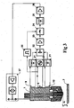
- FIG. 3 are the same reference numerals used to identify the components of the autogenous burner 1 according to the invention, as in FIG. 1 .
- a low-frequency alternating electric field is generated in the field of excitation coil 6, which in turn causes a magnetic polarization in the ferromagnetic material of the burner head 2 at the north pole and south pole with the same frequency.
- the by the change magnetization generated magnetic field lines 13 flow through the autogenous burner and the workpiece 7.
- an electrical signal with an opposite amplitude and a specific phase position of the zero crossing is generated in the two measuring coils 9, 10.
- FIG. 3 1 shows an embodiment for such an evaluation of the phase position of the measurement signals obtained by means of the device according to the invention for the purpose of regulating the working distance between the workpiece surface and the oxy-fuel burner 1.
- the signals detected by the upper measuring coil 9 and the lower measuring coil 10 are respectively fed to a frequency-selective filter 21, whereby the signal noise is suppressed.
- the selected signals are supplied to a potentiometer 22.
- the output voltage at the potentiometer 22 is set in the exemplary embodiment computer-aided to zero.
- the potentiometer signal enters a phase discriminator 24, where it receives a synchronous reference signal from the AC generator 20 is tapped (symbolized by a comparator 25) is compared. Changes in the output signal of the AC voltage generator 20 in the course of a machining process, for example due to a temperature drift, have an equal effect on the reference signal and on the output signals of the measuring coils 9, 10.
- the phase discriminator 24 is a phase-dependent rectifier that can be used to determine whether or not a current phase shift is above the preset "zero".
- the output signals of the phase discriminator 24 evaluate with the correct sign in the filter 25 integrated and then fed via a further amplifier 26 as a control variable for the distance control of a motor controller 27 for the stroke of the autogenous burner 1.
Landscapes
- Engineering & Computer Science (AREA)
- Physics & Mathematics (AREA)
- Plasma & Fusion (AREA)
- Mechanical Engineering (AREA)
- Measurement Of Length, Angles, Or The Like Using Electric Or Magnetic Means (AREA)
- Investigating Or Analyzing Materials By The Use Of Magnetic Means (AREA)
- Machine Tool Sensing Apparatuses (AREA)
Description
Die vorliegende Erfindung betrifft ein Verfahren für die thermische Bearbeitung eines Werkstücks aus einem ferromagnetischen Material mittels eines entlang der Werkstückoberfläche verfahrbaren thermischen Bearbeitungswerkzeuges, gemäß dem Oberbegriff des Anspruchs 1, bei der Werkstückoberfläche ein Wechselmagnetfeld erzeugt wird, das sowohl im Bereich der Werkstückoberfläche als auch in einem Sensorkörper mit ferromagnetischen Eigenschaften oberhalb der Werkstückoberfläche wirkt, wobei das Magnetfeld oder Änderungen desselben mittels einer Messeinrichtung erfasst, und die Messsignale der Messeinrichtung für die Regelung des Arbeitsabstands ausgewertet werden.The present invention relates to a method for the thermal processing of a workpiece made of a ferromagnetic material by means of a movable along the workpiece surface thermal machining tool, according to the preamble of claim 1, wherein the workpiece surface an alternating magnetic field is generated, both in the region of the workpiece surface and in a Sensor body with ferromagnetic properties above the workpiece surface acts, the magnetic field or changes thereof detected by a measuring device, and the measurement signals of the measuring device for the regulation of the working distance are evaluated.
Weiterhin betrifft die Erfindung ein thermische Bearbeitungsmaschine für die Bearbeitung eines Werkstücks aus einem ferromagnetischen Material gemäß dem Oberbegriff des Anspruchs 5, mit einem entlang der Werkstückoberfläche verfahrbaren thermischen Bearbeitungswerkzeug, das einen Brennerkopf aufweist, an dem Schneid- oder Schweißwerkzeuge, welche sich zwischen dem Brennerkopf und der Werkstückoberfläche erstrecken, auswechselbar befestigt sind, und mit einer Abstandsregelung zur Einstellung eines vorgegebenen Arbeitsabstandes zwischen dem Bearbeitungswerkzeug und der Werkstückoberfläche, wobei die Abstandsregelung ein mit dem Bearbeitungswerkzeug bewegbares Erregerelement zum Erzeugen eines Magnetfeldes, das in einem Sensorkörper mit ferromagnetischen Eigenschaften oberhalb der Werkstückoberfläche und im Bereich der Werkstückoberfläche wirksam ist, eine Messeinrichtung zum Erfassen des Magnetfeldes oder von Änderungen desselben und eine Auswerteeinheit umfasst, mittels der Messsignale der Messeinrichtung für die Einstellung einer Stellgröße der Abstandsregelung ausgewertet werden.Furthermore, the invention relates to a thermal processing machine for machining a workpiece made of a ferromagnetic material according to the preamble of
Die thermische Bearbeitung von Werkstücken umfasst das Schweißen, Schneiden.The thermal processing of workpieces includes welding, cutting.
Im Hinblick auf eine hohe Qualität von Schweiß- oder Schneiden an Werkstücken gewinnt zunehmend die Online-Prozessüberwachung bei der thermischen Materialbearbeitung an Bedeutung. Für solche Automatisierungen müssen die Bearbeitungsvorgänge überwacht werden, um Prozessfehler zu vermeiden, die zu einem Ausfall bzw. und zu einer Unterbrechung des Verfahrensablaufs führen würden. Außerdem ist auf eine hohe und möglichst gleichbleibende Qualität eines Schnittes oder einer Schweißnaht zu achten. In diesem Zusammenhang spielt ein gleichbleibender Arbeitsabstand zwischen dem Bearbeitungswerkzeug und dem Werkstück eine wesentliche Rolle. Es sind verschiedene Abstands-Mess- und Regeleinrichtungen bekannt, die induktiv, kapazitiv oder manuell arbeiten.With regard to the high quality of welding or cutting on workpieces, online process monitoring is becoming increasingly important in thermal material processing. For such automations, the processing operations must be monitored to avoid process errors that would lead to failure and / or interruption of the process flow. It is also important to ensure a high and consistent quality of a cut or a weld. In this context, a constant working distance between the machining tool and the workpiece plays an essential role. Various distance measuring and control devices are known which operate inductively, capacitively or manually.
Ein Verfahren zur kapazitiven Abstandsmessung ist beispielsweise aus der
Die kapazitive Messung des Abstandes zwischen Werkstück und Bearbeitungswerkzeug hat jedoch den Nachteil, dass der kapazitive Messwert durch parasitäre Kapazitäten, wie am Werkstück anhaftendem Rost, Oberflächenbeschichtungen, Wasser, Wasserdampf oder sich ändernde Umgebungsbedingungen beeinflusst wird. Auch die Störkontur des am Bearbeitungswerkzeug befestigten Sensorelements oder seines Halters wirken sich auf den Messwert aus. Die Störeffekte werden noch verstärkt, wenn das Bearbeitungswerkzeug und die um es herum angeordneten Komponenten bei der Materialbearbeitung durch Materialrückschlag verschmutzt werden.However, the capacitive measurement of the distance between the workpiece and the machining tool has the disadvantage that the capacitive measured value is influenced by parasitic capacitances, such as rust adhering to the workpiece, surface coatings, water, water vapor or changing environmental conditions. Also, the interference contour of the attached to the machining tool sensor element or its holder affect the reading. The effects of interference are exacerbated when the machining tool and the components arranged around it are soiled during material processing by material kickback.
Es werden auch Bearbeitungsmaschinen eingesetzt, bei denen der Bearbeitungsbereich von einem Wassermantel umgeben ist, um den Austritt umweltschädigender Substanzen zu vermindern. Die sich dabei bildende Pfütze aus leitfähigem Wasser führt ebenfalls zu einer Fehlmessung bei einer kapazitiven Abstandsmessung. Eine Unterwassererfassung von Daten mit kapazitiven Sensoren ist daher nicht möglich.It also machine tools are used, in which the processing area is surrounded by a water jacket to reduce the escape of environmentally harmful substances. The resulting puddle of conductive water also leads to a faulty measurement in a capacitive distance measurement. Underwater detection of data with capacitive sensors is therefore not possible.
Weiterhin ist es bekannt, für die Abstandsmessung induktive Sensoren einzusetzen, wobei um den Brenner eine oder mehrere Inauktionsspulen angeordnet sind, von denen jede als frequenzbestimmendes Element in einem Schwingkreis geschaltet ist, welcher durch eine Induktivitätsänderung der Spule als Folge einer Abstandsänderung zum Werkzeug eine Frequenzänderung bewirkt. Die Auswertung derartiger Frequenzveränderungen erfolgt mittels bekannter Schaltungen oder Bandfiltern.Furthermore, it is known to use inductive sensors for the distance measurement, wherein one or more induc tion coils are arranged around the burner, each of which is connected as a frequency-determining element in a resonant circuit, which causes a change in the inductance of the coil as a result of a change in distance to the tool a frequency change , The evaluation of such frequency changes takes place by means of known circuits or band filters.
Bei den induktiven Sensoren ergeben sich hinsichtlich der Störgrößen die gleichen Probleme wie die oben für die kapazitiven Sensoren beschriebenen. Zudem haben induktive Sensoren den Nachteil, dass sie nur für eine Messung kurzer Arbeitsabstände geeignet sind, da sie hohen thermischen Belastungen nicht standhalten und somit nicht in unmittelbarer Nähe des Bearbeitungsprozesses angeordnet sein können.In the case of the inductive sensors, the same problems arise with regard to the disturbance variables as described above for the capacitive sensors. In addition, inductive sensors have the disadvantage that they are only suitable for measuring short working distances, since they can not withstand high thermal loads and thus can not be arranged in the immediate vicinity of the machining process.
Ein Verfahren und eine thermische Bearbeitungsmaschine sowie ein Bearbeitungswerkzeug gemäß der eingangs genannten Gattung sind aus der
Unter der Voraussetzung, dass das zwischen dem Magnetjochen aufgebaute magnetische Wechselfeld durch das Werkstück bedämpft wird, werden die in den Messspulen induzierten Ströme von der Topografie und dem Abstand des unter dem Sensor liegenden Werkstücks beeinflusst. Diese Bedämpfung ist außer vom Abstand zwischen Schneiddüse und Werkstück auch von Werkstoffeigenschaften des Werkstückes abhängig, wie der magnetischen Permeabilität und seiner elektrischen Leitfähigkeit.Assuming that the alternating magnetic field built up between the magnetic yokes is damped by the workpiece, the currents induced in the measuring coils are influenced by the topography and the distance of the workpiece lying below the sensor. This attenuation depends not only on the distance between the cutting nozzle and the workpiece but also on material properties of the workpiece, such as the magnetic permeability and its electrical conductivity.
Der Abstand der Schneiddüse des Schweißbrenners von der Werkstückoberfläche ist daher eine Funktion der in den Messspulen induzierten Spannung, so dass diese in einer nachgeschalteten Elektronik mit Hilfe einer für den jeweiligen Prozess vorab erstellten Kennlinie in eine Spannung umgesetzt werden kann, die zum Abstand proportional ist und die als Stellgröße für die Abstandsregelung eingesetzt wird. In der Regeleinrichtung können für verschiedene Topographien und Werkstoffe die jeweiligen Kennlinien sowie die typischen Sollwerte für die Arbeitsabstände gespeichert werden.The distance of the cutting nozzle of the welding torch from the workpiece surface is therefore a function of the induced voltage in the measuring coils, so that they can be converted in a downstream electronics using a pre-established for the respective process curve in a voltage that is proportional to the distance and which is used as a manipulated variable for the distance control. In the control device, the respective characteristic curves and the typical setpoint values for the working distances can be stored for different topographies and materials.
Bei der bekannten Vorrichtung ist es erforderlich, dass das magnetische Joch und damit die Erreger- und Messspulen sich in der Nähe des zu bearbeitenden Werkstückes befinden. Dort sind sie einer hohen thermischen Belastung ausgesetzt. Die bestimmungsgemäße Funktion der Vorrichtung kann somit aufgrund der hohen Temperatur oder auch durch Materialrückschlag aus dem bearbeiteten Werkstück beeinträchtigt werden.In the known device, it is necessary that the magnetic yoke and thus the exciter and measuring coils are in the vicinity of the workpiece to be machined. There they are exposed to high thermal stress. The intended function of the device can thus be affected due to the high temperature or by material check from the machined workpiece.
Das separate, den eigentlichen Schneidbrenner umgebende Magnetjoch bewirkt einen breiten Messfleck, der mit einer geringen Messgenauigkeit einhergeht. Es hat sich daher gezeigt, dass die Auswertung der Abstandsmessung bei dem bekannten Verfahren mit einem großen Messfehler behaftet ist.The separate, surrounding the actual cutting torch magnetic yoke causes a wide spot, which is associated with a low accuracy. It has therefore shown that the evaluation of the distance measurement in the known method is associated with a large measurement error.
Bei Änderungen der Prozessparameter, wie etwa dem zu bearbeitendem Werkstoff, seiner Topographie oder bei einem Wechsel des Bearbeitungswerkzeugs ist für die Regelung des Arbeitsabstands eine neue Kennlinie erforderlich, die aufwändig erzeugt werden muss.When changing the process parameters, such as the material to be machined, its topography or when changing the machining tool for the regulation of the working distance a new characteristic curve is required, which must be laboriously generated.
Aus der
Der Erfindung liegt daher die Aufgabe zugrunde, ein Verfahren für die thermische Bearbeitung eines Werkstückes anzugeben, bei dem der Arbeitsabstand zwischen dem Bearbeitungswerkzeug und dem Werkstück auf einfache Art und Weise und gleichzeitig mit hoher Genauigkeit eingestellt und geregelt werden kann, und das gegen äußere Störeinflüsse weitgehend unempfindlich ist.The invention is therefore based on the object of specifying a method for the thermal processing of a workpiece, in which the working distance between the machining tool and the workpiece can be adjusted and controlled in a simple manner and at the same time with high accuracy, and largely against external interference insensitive.
Weiterhin liegt der Erfindung die Aufgabe zugrunde, eine geeignete Bearbeitungsmaschine bereitzustellen, welche eine punktuelle Messung des Arbeitsabstandes ermöglicht und die auch für die Messung großer Abstände geeignet ist.Furthermore, the invention has for its object to provide a suitable processing machine, which allows a punctual measurement of the working distance and which is also suitable for the measurement of large distances.
Hinsichtlich des Verfahrens wird diese Aufgabe ausgehend von dem eingangs genannten Verfahren erfindungsgemäß dadurch gelöst, dass als Sensorkörper der Brennerkopf und mindestens eines der Schneid- oder Schweißwerkzeuge eingesetzt werden.With regard to the method, this object is achieved on the basis of the above-mentioned method according to the invention that as a sensor body the burner head and at least one of the cutting or welding tools are used.
Beim erfindungsgemäßen Verfahren wird zur Einstellung des Arbeitsabstandes zwischen der Werkstückoberfläche und dem thermischen Bearbeitungswerkzeug ein magnetisches System eingesetzt, bei dem der Sensorkörper durch den Brennerkopf und mindestens eines der am Brennerkopf fixierten Schneid- oder Schweißwerkzeuge gebildet wird.In the method according to the invention, a magnetic system is used to adjust the working distance between the workpiece surface and the thermal processing tool, in which the sensor body is formed by the burner head and at least one of the cutting or welding tools fixed to the burner head.
Der Brennerkopf und das betreffende mindestens eine Schneid- oder Schweißwerkzeug weisen deshalb ferromagnetische Eigenschaften auf. Diese Teile sind vollständig oder teilweise aus einem ferromagnetischen Material gefertigt. Eine Beschichtung der Teile, beispielsweise zum Schutz vor Oxidation, beeinträchtigt das erfindungsgemäße Verfahren nicht.The burner head and the relevant at least one cutting or welding tool therefore have ferromagnetic properties. These parts are completely or partially made of a ferromagnetic material. A coating of the parts, for example, to protect against oxidation, does not affect the inventive method.
Bei den insgesamt mit dem Brennerkopf verbundenen Schneid- oder Schweiß-werkzeugen handelt es sich in der Regel um eine Schneiddüse, die häufig von einer Heizdüse umgeben ist, oder um eine Elektrode (bei einem Plasmabrenner). Schneid- und Heizdüse werden häufig mittels eines Halteringes, der die Düsen kappenförmig umgreift, an dem Brennerkopf fixiert. Eines dieser Teile zwischen Brennerkopf und Werkstückoberfläche (wie: Düse Elektrode, Heizdüse, Haltekappe), mehrere oder alle diese Teile weisen ferromagnetische Eigenschaften auf und werden im Folgenden auch als "Sensorspitze" bezeichnet.The cutting or welding tools connected generally to the burner head are usually a cutting nozzle, which is often surrounded by a heating nozzle, or an electrode (in the case of a plasma torch). Cutting and heating nozzle are often fixed by means of a retaining ring which surrounds the nozzle cap-shaped, on the burner head. One of these parts between the burner head and workpiece surface (such as: nozzle electrode, heating nozzle, retaining cap), several or all of these parts have ferromagnetic properties and are also referred to below as the "sensor tip".
Der Verlust an magnetischer Feldstärke ist umso geringer, je größer der Querschnitt an ferromagnetischem Material von der Erregerstelle bis zur Werkstückoberfläche ist. Das Material mit ferromagnetischen Eigenschaften ist in der Regel Eisen oder eine eisenhaltige Legierung. Der Brennerkopf und die Sensorspitze bestehen aus dem gleichen Material oder aus unterschiedlichen Materialien. Wesentlich ist, dass das Material des Sensorkörpers insgesamt in einem elektrischen Wechselfeld magnetisch polarisierbar ist und dass die magnetische Feldstärke im Bereich der Werkstückoberfläche messbar ist und durch das Werkstück bedämpft wird.The smaller the cross section of ferromagnetic material from the excitation site to the workpiece surface, the lower the loss of magnetic field strength. The material with ferromagnetic properties is usually iron or an iron-containing alloy. The torch head and sensor tip are made of the same material or different materials. It is essential that the material of the sensor body is magnetically polarizable overall in an alternating electrical field and that the magnetic field strength in the region of the workpiece surface can be measured and is damped by the workpiece.
Mittels des Sensorkörpers wird die magnetische Polarisation von der Stelle ihrer Erregung in Richtung auf die Werkstückoberfläche übertragen, was schematisch durch magnetische Feldlinien dargestellt werden kann, welche in einer geschlossenen Bahn von der Erregungsstelle ausgehend über den Brennerkopf und die Sensorspitze verlaufen und bei ihrem Rückweg mit dem Werkstück so in Wechselwirkung treten, dass das magnetische Feld bedämpft wird. Eine Änderung des Abstandes zwischen Sensorspitze und Werkstückoberfläche macht sich daher in einer Änderung der Eigenschaften des magnetischen Feldes bemerkbar. Diese Änderung der Eigenschaften des magnetischen Feldes wird für eine Abstandsregelung herangezogen, wie dies weiter unten noch näher erläutert wird.By means of the sensor body, the magnetic polarization is transmitted from the point of their excitation in the direction of the workpiece surface, which can be schematically represented by magnetic field lines, which extend in a closed path from the excitation site on the burner head and the sensor tip and on their return to the Interact workpiece so that the magnetic field is damped. A change in the distance between the sensor tip and the workpiece surface is therefore noticeable in a change in the properties of the magnetic field. This change in the properties of the magnetic field is used for a distance control, as will be explained in more detail below.
Der Sensorkörper wird durch den Brennerkopf und die Sensorspitze gebildet und mittels diesem das erzeugte magnetische Feld bis an die Werkstückoberfläche herangeführt und so auf den Bereich des Schneidprozesses fokussiert. Dadurch wird eine punktgenaue Abstandsregelung erleichtert. Ein separater, außerhalb des Brennerkopfes anzuordnender Sensorkörper - wie im Stand der Technik vorgeschlagen ― ist nicht erforderlich.The sensor body is formed by the burner head and the sensor tip and by means of this the magnetic field generated is brought up to the workpiece surface and thus focused on the region of the cutting process. This facilitates a precise distance control. A separate, outside the burner head to be arranged sensor body - as proposed in the prior art - is not required.
Die Erregung des magnetischen Feldes erfolgt in einer Entfernung von der Werkstückoberfläche, die einerseits eine geringe Beeinträchtigung des Erregungsmittels durch die Prozesstemperatur und andererseits eine für die Auswertung genügend große magnetische Feldstärke im Bereich der Werkstückoberfläche gewährleistet. Die Stelle der Magnetfelderregung befindet sich im Bereich des Brennerkopfes oder außerhalb davon. Im Hinblick auf die Messgenauigkeit ist es günstig, dass der Brennerkopf bei den üblichen Bearbeitungswerkzeugen eine vergleichsweise große Masse aufweist, und daher über den Brennerkopf ein großer Querschnitt mit ferromagnetischem Material zur Verfügung gestellt werden kann, so dass die Verluste im elektrischen Wechselfeld gering sind.The excitation of the magnetic field takes place at a distance from the workpiece surface, on the one hand ensures a slight deterioration of the excitation means by the process temperature and on the other hand sufficient for the evaluation magnetic field strength in the region of the workpiece surface. The location of the magnetic field excitation is in the area of the burner head or outside it. With regard to the measurement accuracy, it is favorable that the burner head has a comparatively large mass in the case of the usual machining tools, and therefore a large cross-section with ferromagnetic material can be made available via the burner head, so that the losses in the alternating electric field are low.
Eine Verbesserung des erfindungsgemäßen Verfahrens wird dadurch erreicht, dass das Magnetfeld mittels einer Erregerspule erzeugt wird, durch welche sich der Sensorkörper so erstreckt, dass er oberhalb und unterhalb einer Querschnittsebene, durch welche eine mittlere Spulenebene der Erregerspule verläuft, von magnetischen Feldlinien durchflossen wird, wobei die magnetischen Feldlinien oberhalb der Spulenebene mittels eines oberen Messelements erfasst werden und dabei ein erstes Messsignal erzeugt wird, das eine erste Amplitude und eine erste Phase aufweist, und wobei die magnetischen Feldlinien unterhalb der Spulenebene mittels eines unteren Messelements erfasst werden und dabei ein zweites Messsignal erzeugt wird, das eine zweite Amplitude und eine zweite Phase aufweist, wobei die relative Lage zwischen erster Phase und zweiter Phase ermittelt und als Phasenverschiebung für die Regelung des Arbeitsabstands verwendet wird.An improvement of the method according to the invention is achieved in that the magnetic field is generated by means of an excitation coil, through which the sensor body extends so that it flows through magnetic field lines above and below a cross-sectional plane through which a central coil plane of the excitation coil passes the magnetic field lines are detected above the coil plane by means of an upper measuring element and thereby a first measuring signal is generated which has a first amplitude and a first phase, and wherein the magnetic field lines are detected below the coil plane by means of a lower measuring element and thereby generates a second measuring signal which has a second amplitude and a second phase, wherein the relative position between the first phase and second phase is determined and used as a phase shift for the control of the working distance.
Hierbei wird zur Erzeugung des Magnetfeldes eine Erregerspule eingesetzt, die den Sensorkörper umgibt, so dass in diesem ein rotationssymmetrisches, zu einer Sensorkörper-Längsachse koaxiales Magnetfeld erzeugt werden kann. Durch die Rotationssymmetrie des Magnetfeldes werden Vorzugsrichtungen oder Abschattungen vermeiden, so dass sich die Abstandsmessung in allen lateralen Richtungen gleich verhält, was zu einer höheren Messgenauigkeit führt.In this case, an excitation coil is used to generate the magnetic field, which surrounds the sensor body, so that in this a rotationally symmetrical, to a Sensor body longitudinal axis coaxial magnetic field can be generated. Due to the rotational symmetry of the magnetic field, preferred directions or shadowing are avoided, so that the distance measurement behaves identically in all lateral directions, which leads to a higher measurement accuracy.
Die Erregerspule ist in Bezug auf den Sensorkörper so angeordnet, dass sich dieser oberhalb und unterhalb der Erregerspule erstreckt, insbesondere erstreckt er sich oberhalb und unterhalb einer Querschnittsebene, durch welche die mittlere Spulenebene der Erregerspule verläuft. Die mittlere Spulenebene befindet sich in der Hälfte der Höhe der Erregerspule. Das so erzeugte magnetische Feld hat einen Anteil oberhalb der mittleren Spulenebene und einen Anteil unterhalb davon. Diese Anteile des magnetischen Feldes werden separat mittels eines oberen Messelements bzw. mittels eines unteren Messeelementes erfasst.The exciter coil is arranged with respect to the sensor body so that it extends above and below the exciter coil, in particular it extends above and below a cross-sectional plane through which the central coil plane of the exciter coil extends. The middle coil plane is located in the half of the height of the exciter coil. The magnetic field generated in this way has a portion above the middle coil level and a portion below it. These portions of the magnetic field are detected separately by means of an upper measuring element or by means of a lower measuring element.
Es sind demnach mindestens zwei Messelemente vorgesehen, welche jeweils ein Messsignal in Form eines elektrischen Wechselfeldes erzeugen, das eine Amplitude aufweist, die von der magnetischen Feldstärke in dem betreffenden Bereich abhängt, und das jeweils eine bestimmte Phasenlage für den Nulldurchgang aufweist.Accordingly, at least two measuring elements are provided which in each case generate a measuring signal in the form of an alternating electric field which has an amplitude which depends on the magnetic field strength in the relevant area and which in each case has a specific phase position for the zero crossing.
Erfindungsgemäß wird nicht die Amplitude für die Regelung des Arbeitsabstandes ausgewertet, sondern die relative Lage zwischen den Phasen des ersten und des zweiten Messsignals. Denn es wurde gefunden, dass sich einer Änderung des Arbeitsabstandes nicht nur auf die Amplitude, sondern auch auf die Phasenlage der Messsignale auswirkt. Eine Änderung des Arbeitsabstandes bewirkt eine relative Verschiebung der Phasenlage von erstem und zweitem Messsignal. Diese Phasenverschiebung wird erfindungsgemäß für die Regelung des Arbeitsabstandes verwendet, denn es hat sich weiterhin gezeigt, dass die Phasenverschiebung unempfindlicher auf Störgrößen im Bereich des magnetischen Feldes reagiert als die Amplitude des Messsignals, so dass die Auswertung der Phasenverschiebung eine größere Messgenauigkeit ergibt.According to the invention, the amplitude for the regulation of the working distance is not evaluated, but the relative position between the phases of the first and the second measuring signal. For it has been found that a change in the working distance affects not only the amplitude but also the phase position of the measuring signals. A change in the working distance causes a relative shift of the phase position of the first and second measurement signal. This phase shift is used according to the invention for the control of the working distance, because it has been shown that the phase shift is less sensitive to disturbances in the field of the magnetic field than the amplitude of the measurement signal, so that the evaluation of the phase shift results in a greater accuracy.
Darüber hinaus entfällt bei der erfindungsgemäßen Verfahrensweise die Notwendigkeit, für die Auswertung der Messsignale in Bezug auf den Arbeitsabstand eine Kennlinie erstellen zu müssen. Für die Abstandsregelung genügt es, den Ausgangswert der Phasenverschiebung beim Sollwert des Arbeitsabstandes festzustellen und bei Abweichungen hiervon, den Abstand nachzuregeln.Moreover, in the method according to the invention, there is no need to create a characteristic curve for the evaluation of the measuring signals in relation to the working distance. For the distance control it is sufficient, the output value determine the phase shift at the setpoint of the working distance and in case of deviations, the distance readjust.
Vorzugsweise sind das obere Messelement als obere Messspule, und das untere Messelement als untere Messspule ausgebildet, wobei die obere Messspule und die untere Messspule so miteinander verbunden sind, dass sich die erste und die zweite Amplitude mindestens teilweise gegenseitig kompensieren.Preferably, the upper measuring element as the upper measuring coil, and the lower measuring element formed as a lower measuring coil, wherein the upper measuring coil and the lower measuring coil are connected to each other, that the first and the second amplitude at least partially compensate each other.
Die Ausbildung der Messelemente in Form von Messspulen ergibt ein im Wesentlichen temperaturunabhängiges Messsignal. Die Messspulen sind dabei so verschaltet, dass sich die Amplituden der beiden Messsignale gegenseitig zumindest teilweise kompensieren. Dadurch wird die Auswertung der Phasenverschiebung erleichtert. Zur Erzeugung eines elektrischen Signals ist eine Bewegung von elektrisch leitenden Teilen innerhalb der Messspulen nicht erforderlich.The formation of the measuring elements in the form of measuring coils results in a substantially temperature-independent measuring signal. The measuring coils are connected so that the amplitudes of the two measurement signals compensate each other at least partially. This facilitates the evaluation of the phase shift. To generate an electrical signal, a movement of electrically conductive parts within the measuring coils is not required.
Ein besonders günstiges Ergebnis ergibt sich dann, wenn eine koaxial um eine Mittelachse des Sensorkörpers verlaufende Erregerspule eingesetzt wird.A particularly favorable result is obtained when a coaxially extending around a central axis of the sensor body excitation coil is used.
Durch Einsatz einer koaxial um die Mittelachse des Sensorkörpers verlaufenden Erregerspule wird ein rotationssymmetrisches Magnetfeld erzeugt, das auf den Punkt des Schneidprozesses fokussiert ist und das daher keine Vorzugsrichtung aufweist. In Verbindung mit einer ebenso rotationssymmetrischen Erfassung des Magnetfeldes durch Messspulen, welche koaxial um die Mittelachse des Sensorkörpers verlaufen, ergibt sich eine hohe Messgenauigkeit.By using a coaxially extending around the central axis of the sensor body exciter coil, a rotationally symmetric magnetic field is generated, which is focused on the point of the cutting process and therefore has no preferred direction. In conjunction with an equally rotationally symmetrical detection of the magnetic field by measuring coils, which extend coaxially around the central axis of the sensor body, results in a high accuracy of measurement.
Hinsichtlich des thermischen Bearbeitungswerkzeugs wird die obengenannte Aufgabe ausgehend von dem gattungsgemäßen Bearbeitungswerkzeug erfindungsgemäß dadurch gelöst, dass der Brennerkopf und mindestens eines der Schneidoder Schweißwerkzeuge ferromagnetisches Material enthalten und mindestens einen Teil des Sensorkörpers bilden.With regard to the thermal machining tool, the above-mentioned object is achieved on the basis of the generic machining tool according to the invention in that the burner head and at least one of the cutting or welding tools contain ferromagnetic material and form at least part of the sensor body.
Für die Einstellung des Arbeitsabstandes zwischen der Werkstückoberfläche und dem thermischen Bearbeitungswerkzeug wird erfindungsgemäß ein magnetisches System eingesetzt, bei dem der Sensorkörper durch den Brennerkopf und mindestens eines der am Brennerkopf fixierten Schneid- oder Schweißwerkzeuge gebildet wird.For setting the working distance between the workpiece surface and the thermal processing tool, a magnetic system is used according to the invention, in which the sensor body is formed by the burner head and at least one of the fixed to the burner head cutting or welding tools.
Der Brennerkopf und das betreffende mindestens eine Schneid- oder Schweißwerkzeug weisen deshalb ferromagnetische Eigenschaften auf. Diese Teile sind vollständig oder teilweise aus einem ferromagnetischen Material gefertigt. Eine Beschichtung der Teile, beispielsweise zum Schutz vor Oxidation, beeinträchtigt das Ergebnis nicht wesentlich.The burner head and the relevant at least one cutting or welding tool therefore have ferromagnetic properties. These parts are made entirely or partially of a ferromagnetic material. A coating of the parts, for example to protect against oxidation, does not significantly affect the result.
Bei den insgesamt mit dem Brennerkopf verbundenen Schneid- oder Schweißwerkzeugen handelt es sich in der Regel um eine Schneiddüse, die von einer Heizdüse umgeben ist. Schneid- und Heizdüse werden häufig mittels eines Halteringes, der die Düsen kappenförmig umgreift, an dem Brennerkopf fixiert. Bei einem Plasmabrenner bildet die Elektrode ein wesentliches Schneid- oder Schweißwerkzeug im Sinne der Erfindung. Eines der Teile zwischen Brennerkopf und Werkstückoberfläche, mehrere oder alle diese Teile weisen ferromagnetische Eigenschaften auf und werden im Folgenden auch als "Sensorspitze" bezeichnet.The total associated with the burner head cutting or welding tools is usually a cutting nozzle, which is surrounded by a heating nozzle. Cutting and heating nozzle are often fixed by means of a retaining ring which surrounds the nozzle cap-shaped, on the burner head. In the case of a plasma torch, the electrode forms an essential cutting or welding tool in the sense of the invention. One of the parts between the burner head and the workpiece surface, several or all of these parts have ferromagnetic properties and are also referred to below as the "sensor tip".
Der Verlust an magnetischer Feldstärke ist umso geringer, je größer der Querschnitt an ferromagnetischem Material von der Erregerstelle bis zur Werkstückoberfläche ist. Das Material mit ferromagnetischen Eigenschaften ist in der Regel Eisen oder eine eisenhaltige Legierung. Der Brennerkopf und die Sensorspitze bestehen aus dem gleichen Material oder aus unterschiedlichen Materialien. Wesentlich ist, dass das Material des Sensorkörpers insgesamt in einem elektrischen Wechselfeld magnetisch polarisierbar ist und dass die magnetische Feldstärke im Bereich der Werkstückoberfläche messbar ist und durch das Werkstück bedämpft wird.The smaller the cross section of ferromagnetic material from the excitation site to the workpiece surface, the lower the loss of magnetic field strength. The material with ferromagnetic properties is usually iron or an iron-containing alloy. The torch head and sensor tip are made of the same material or different materials. It is essential that the material of the sensor body is magnetically polarizable overall in an alternating electrical field and that the magnetic field strength in the region of the workpiece surface can be measured and is damped by the workpiece.
Mittels des Sensorkörpers wird die magnetische Polarisation von der Stelle ihrer Erregung in Richtung auf die Werkstückoberfläche übertragen, was schematisch durch magnetische Feldlinien dargestellt werden kann, welche in einer geschlossenen Bahn von der Erregungsstelle ausgehend über den Brennerkopf und die Sensorspitze verlaufen und bei ihrem Rückweg mit dem Werkstück so in Wechselwirkung treten, dass das magnetische Feld bedämpft wird. Eine Änderung des Abstandes zwischen Sensorspitze und Werkstückoberfläche macht sich daher in einer Änderung der Eigenschaften des magnetischen Feldes bemerkbar. Diese Änderung der Eigenschaften des magnetischen Feldes wird für eine Abstandsregelung herangezogen, wie dies oben anhand des erfindungsgemäßen Verfahrens erläutert ist.By means of the sensor body, the magnetic polarization is transmitted from the point of their excitation in the direction of the workpiece surface, which can be schematically represented by magnetic field lines, which extend in a closed path from the excitation site on the burner head and the sensor tip and on their return to the Interact workpiece so that the magnetic field is damped. A change in the distance between the sensor tip and the workpiece surface is therefore noticeable in a change in the properties of the magnetic field. This change in the properties of the magnetic field is used for a distance control used, as explained above with reference to the method according to the invention.
Der Sensorkörper wird durch den Brennerkopf und die Sensorspitze gebildet und mittels diesem das erzeugte magnetische Feld bis an die Werkstückoberfläche herangeführt und so auf den Bereich des Schneidprozesses fokussiert. Dadurch wird eine punktgenaue Abstandsregelung erleichtert. Ein separater, außerhalb des Brennerkopfes anzuordnender Sensorkörper - wie im Stand der Technik vorgeschlagen ― ist nicht erforderlich.The sensor body is formed by the burner head and the sensor tip and by means of this the magnetic field generated is brought up to the workpiece surface and thus focused on the region of the cutting process. This facilitates a precise distance control. A separate, outside the burner head to be arranged sensor body - as proposed in the prior art - is not required.
Die Erregung des magnetischen Feldes erfolgt in einer Entfernung von der Werkstückoberfläche, die einerseits eine geringe Beeinträchtigung des Erregungsmittels durch die Prozesstemperatur und andererseits eine für die Auswertung genügend größe magnetische Feldstärke im Bereich der Werkstückoberfläche gewährleistet. Die Stelle der Magnetfelderregung befindet sich im Bereich des Brennerkopfes oder außerhalb davon. Im Hinblick auf die Messgenauigkeit ist es günstig, dass der Brennerkopf bei den üblichen Bearbeitungswerkzeugen eine vergleichsweise große Masse aufweist, und daher über den Brennerkopf ein großer Querschnitt mit ferromagnetischem Material zur Verfügung gestellt werden kann, so dass die Verluste im elektrischen Wechselfeld gering sind.The excitation of the magnetic field takes place at a distance from the workpiece surface, on the one hand ensures a slight deterioration of the excitation means by the process temperature and on the other hand sufficient for the evaluation magnetic field strength in the region of the workpiece surface. The location of the magnetic field excitation is in the area of the burner head or outside it. With regard to the measurement accuracy, it is favorable that the burner head has a comparatively large mass in the case of the usual machining tools, and therefore a large cross-section with ferromagnetic material can be made available via the burner head, so that the losses in the alternating electric field are low.
Es hat sich als vorteilhaft erwiesen, wenn das Erregerelement als Erregerspule ausgebildet ist, durch welche sich der Sensorkörper so erstreckt, dass in ihm magnetische Feldlinien oberhalb und unterhalb einer Querschnittsfläche verlaufen, welche die mittlere Spulenebene der Erregerspule umfasst, wobei ein oberes Messelement und ein unteres Messelement vorgesehen sind, und wobei sich das obere Messelement im Bereich oberhalb der mittleren Spulenebene, und das untere Messelement im Bereich unterhalb der mittleren Spulenebene erstrecken.It has proven to be advantageous if the exciter element is designed as an exciter coil through which the sensor body extends so that magnetic field lines run in it above and below a cross-sectional area which comprises the central coil plane of the exciter coil, wherein an upper measuring element and a lower Measuring element are provided, and wherein the upper measuring element extend in the region above the central coil plane, and the lower measuring element in the region below the central coil plane.
Das Erregerelement ist erfindungsgemäß als Erregerspule ausgebildet, welche den Sensorkörper umgibt. Dabei ist der Sensorkörper innerhalb der Erregerspule so angeordnet, dass in ihm eine magnetische Polarisation erzeugt wird, mit Feldlinien oberhalb und unterhalb einer Querschnittsfläche, in welcher die mittlere Spulenebene der Erregerspule liegt. Oberhalb und unterhalb dieser Spulenebene sind ein oberes Messelement und ein unteres Messelement vorgesehen, die Teil der Messeinrichtung sind. Das obere Messelement erstreckt sich mindestens teilweise entlang des Sensorkörpers im Bereich oberhalb der mittleren Spulenebene, und das untere Messelement erstreckt sich mindestens teilweise entlang des Bereichs unterhalb der mittleren Spulenebene. Im einfachsten Fall ist das obere Messelement oberhalb der Erregerspule und das untere Messelement unterhalb derselben angeordnet. Bei einer Übereinander-Anordnung von Erregerspulen und Messelementen ergibt sich ein geringer seitlicher Aufbau, so dass ein besonders schmales Bearbeitungswerkzeugs ermöglicht wird. Alternativ dazu sind die beiden Messelemente beispielsweise unmittelbar übereinander vor oder hinter der Erregerspule angeordnet.The excitation element is inventively designed as an excitation coil, which surrounds the sensor body. In this case, the sensor body within the excitation coil is arranged so that in it a magnetic polarization is generated, with field lines above and below a cross-sectional area in which the central coil plane of the exciter coil is located. Above and below this coil plane, an upper measuring element and a lower measuring element are provided, the part the measuring device are. The upper measuring element extends at least partially along the sensor body in the region above the central coil plane, and the lower measuring element extends at least partially along the region below the central coil plane. In the simplest case, the upper measuring element above the excitation coil and the lower measuring element is arranged below the same. In a superposed arrangement of excitation coils and measuring elements results in a small lateral structure, so that a particularly narrow machining tool is made possible. Alternatively, the two measuring elements are, for example, arranged directly above one another in front of or behind the exciter coil.
Die Messeinrichtung erlaubt eine Auswertung von Messsignalen unter Verwendung der Phasenverschiebung des Messsignals, wie es oben an Hand des erfindungsgemäßen Verfahrens näher beschrieben ist.The measuring device allows an evaluation of measurement signals using the phase shift of the measurement signal, as described in more detail above with reference to the method according to the invention.
Die Messelemente sind beispielsweise seitlich zum Sensorkörper angeordnet. In einer besonders bevorzugten Ausführungsform des erfindungsgemäßen Bearbeitungswerkzeuges sind die Messelemente jedoch in Form einer oberen Messspule und einer unteren Messspule ausgebildet, wobei die obere Messspule, die untere Messspule und die Erregerspule eine gemeinsame Mittelachse aufweisen, in welcher sich der Sensorkörper erstreckt.The measuring elements are arranged, for example, laterally to the sensor body. In a particularly preferred embodiment of the machining tool according to the invention, however, the measuring elements are designed in the form of an upper measuring coil and a lower measuring coil, wherein the upper measuring coil, the lower measuring coil and the exciter coil have a common central axis in which the sensor body extends.
Die Ausbildung der Messeinrichtungen in Form von Messspulen anstelle anderer Magnetfeld-Messeinrichtungen, wie Hall-Sensoren oder Magnetfeldsensoren hat den Vorteil, dass das erhaltene Messsignal im wesentlichen temperaturunabhängig ist.The design of the measuring devices in the form of measuring coils instead of other magnetic field measuring devices, such as Hall sensors or magnetic field sensors has the advantage that the measurement signal obtained is substantially independent of temperature.
Die koaxiale Anordnung der Erregerspule und der Messspulen um eine gemeinsame Mittelachse, in welcher der Sensorkörpers verläuft, ermöglicht die Erzeugung und Auswertung eines rotationssymmetrischen Magnetfelds, das auf den Punkt des Schneidprozesses fokussiert ist, sowie eine dazu symmetrische Erfassung des Magnetfelds mittels der Messspulen.The coaxial arrangement of the excitation coil and the measuring coils about a common central axis, in which the sensor body extends, enables the generation and evaluation of a rotationally symmetrical magnetic field, which is focused on the point of the cutting process, as well as a symmetrical detection of the magnetic field by means of the measuring coils.
Es hat sich besonders bewährt, wenn die obere Messspule und die untere Messspule so ausgelegt sind, dass sich die in den Messspulen erzeugten Spannungen in der Arbeitsposition des Bearbeitungswerkzeugs kompensieren.It has proven particularly useful if the upper measuring coil and the lower measuring coil are designed so that the voltages generated in the measuring coils compensate each other in the working position of the machining tool.
Die Spulen sind hinsichtlich ihrer Windungszahl und Größe so ausgelegt, dass in der Arbeitsposition die Amplituden der in den Messspulen erzeugten Spannungen sich etwa zu Null addieren. Dadurch wird gewährleistet, dass sich bei Änderungen des Arbeitsabstandes die Messsignale der beiden Messspulen in etwa proportional verändern, damit wird eine Auswertung der Phasenverschiebung wie oben an Hand des erfindungsgemäßen Verfahrens beschrieben, erleichtert.The coils are designed in terms of their number of turns and size so that in the working position, the amplitudes of the voltages generated in the measuring coils add up to about zero. This ensures that the measured signals of the two measuring coils change approximately proportionally as the working distance changes, thereby facilitating evaluation of the phase shift as described above with reference to the method according to the invention.
Vorteilhafterweise bestehen der Brennerkopf und das mindestens eine Schneid- oder Schweißwerkzeug vollständig aus ferromagnetischem Material.Advantageously, the burner head and the at least one cutting or welding tool are made entirely of ferromagnetic material.
Im Hinblick auf die Messgenauigkeit ist es günstig, wenn mittels des Brennerkopfes ein großer Querschnitt an ferromagnetischem Material zu Verfügung gestellt wird, so dass Verluste der magnetischen Feldstärke gering gehalten werden können. Ein aus ferromagnetischem Material bestehender Brennerkopf kann, beispielsweise zum Schutz des eisenhaltigen Materials vor Oxidation, mit einer Beschichtung versehen sein. Dies gilt gleichermaßen für das mindestens eine der Schneid- oder Schweißwerkzeuge.With regard to the measurement accuracy, it is favorable if a large cross section of ferromagnetic material is made available by means of the burner head, so that losses of the magnetic field strength can be kept low. A torch head made of ferromagnetic material may be provided with a coating, for example to protect the ferrous material from oxidation. This applies equally to the at least one of the cutting or welding tools.
Nachfolgend wird die Erfindung anhand von Ausführungsbeispielen und einer Zeichnung näher beschrieben, in der Zeichnung zeigt im Einzelnen in schematischer Darstellung:
- Figur 1
- eine Ausführungsform des erfindungsgemäßen Bearbeitungswerkzeugs in Form eines Autogenschneidbrenners,
-
Figur 2 - eine schematische Darstellung des Verlaufs der magnetischen Feldlinien innerhalb und außerhalb des Schneidbrenners, und
-
Figur 3 - die Ausführungsform des erfindungsgemäßen Bearbeitungswerkzeugs gemäß
Figur 1 , ergänzt um ein Schaltbild zur Auswertung der Messsignale.
- FIG. 1
- an embodiment of the machining tool according to the invention in the form of an autogenous cutting torch,
- FIG. 2
- a schematic representation of the course of the magnetic field lines inside and outside the cutting torch, and
- FIG. 3
- the embodiment of the processing tool according to the invention according to
FIG. 1 , supplemented by a circuit diagram for the evaluation of the measuring signals.
Der Brennerkopf 2 weist eine Mittelachse 8 auf, entlang der eine Leitung 11 für die Zufuhr von Schneidsauerstoff zur Schneiddüse 3 verläuft. Weiterhin ist eine Leitung 12 für die Zufuhr von Brenngas vorgesehen.The
Brennerkopf 2, Schneiddüse 3, Heizdüse 4 und Haltekappe 5 sind mechanisch miteinander in Kontakt und werden mittels einer Erregerspule 6, die mit einem Wechselspannungsgenerator 20 verbunden ist, mit wechselnder Polarität magnetisch polarisiert. Der Wechselspannungsgenerator 20 kann als separates Bauteil ausgebildet sein, oder die Netzfrequenz nutzen. Durch die Magnetisierung bilden sich die in
Eine weitere Besonderheit des erfindungsgemäßen thermischen Bearbeitungswerkzeuges besteht darin, dass die Erregerspule 6 den Brennerkopf 2 koaxial zu dessen Mittelachse 8 umgibt, wodurch ein rotationssymmetrisches magnetisches Feld entsteht, wie dies in der schematischen Darstellung von
Oberhalb der Erregerspule 6 ist eine obere Messspule 9 und unterhalb davon eine untere Messspule 10 vorgesehen. Sie umgeben den Brennerkopf 2 ebenfalls koaxial zu dessen Mittelachse 8, so dass eine rotationssymmetrische Erfassung der magnetischen Feldlinien 13 ermöglicht wird, wie dies aus
Das erfindungsgemäße Verfahren zur Bearbeitung eines Werkstücks wird nachfolgend anhand von
In
Bei Abstandsänderungen des Autogenbrenners 1 zum Werkstück 7 verlängern oder verkürzen sich die Feldlinien 13. Dadurch ergibt sich für beide Messspulen 9, 10 nicht nur eine Änderung der Amplitude des jeweiligen Signals, sondern auch eine Verschiebung der Phasenlage. Für die Regelung des Arbeitsabstandes wird nicht die Amplitude des Signals der Messspulen 9, 10 ausgewertet, sondern ausschließlich die Phasenverschiebungen der in den Messspulen 9, 10 erzeugten Spannungen.With changes in the distance of the autogenous burner 1 to the
Hierzu werden die von der oberen Messspule 9 und der unteren Messspule 10 erfassten Signale jeweils einem frequenzselektiven Filter 21 eingespeist, wodurch das Signalrauschen unterdrückt wird. Die selektierten Signale werden einem Potentiometer 22 zugeführt. Die Ausgangsspannung am Potentiometer 22 wird im Ausführungsbeispiel rechnergestützt auf Null eingestellt. Durch den Nullabgleich wird die oben erwähnte anfängliche Asymmetrie der Feldünienverteilung unter Berücksichtigung des vorgegebenen Soll-Arbeitsabstandes ausgeglichen, soweit dies nicht bereits durch Auslegung der Messspulen 9; 10 erfolgt ist. Auf diese Weise werden somit die Amplituden der Spannungssignale aus den Messspulen 9 und 10 unter Berücksichtigung des Soll-Arbeitsabstand gegenseitig kompensiert und das Restsignal auf den Wert Null eingestellt. Diese Maßnahme erleichtert die Auswertung der Phasenverschiebung bei einer Änderung des Arbeitsabstandes "A" zwischen dem Autogenschneidbrenner 1 und der Oberfläche des Werkstücks 7.For this purpose, the signals detected by the
Über einen Verstärker 23 gelangt das Potentiometersignal in einen Phasendiskriminator 24, wo es mit einem synchronen Referenzsignal, das von dem Wechselspannungsgenerator 20 abgegriffen wird (symbolisiert durch einen Komparator 25), verglichen wird. Änderungen des Ausgangssignals des Wechselspannungsgenerators 20 im Verlaufe eines Bearbeitungsprozesses, beispielsweise infolge einer Temperaturdrift, wirken sich auf das Referenzsignal und auf die Ausgangssignale der Messspulen 9, 10 gleichermaßen aus.Via an
Bei dem Phasendiskriminator 24 handelt es sich um einen phasenabhängigen Gleichrichter, anhand dessen festgestellt werden kann, ob eine aktuelle Phasenverschiebung über dem voreingestellten "Null" liegt, oder darunter. Die Ausgangssignale des Phasendiskriminators 24 werten vorzeichenrichtig in dem Filter 25 aufintegriert und anschließend über einen weiteren Verstärker 26 als Stellgröße für die Abstandsregelung einer Motorsteuerung 27 für den Hub des Autogenbrenners 1 zugeführt.The
Claims (9)
- A method for thermally working a workpiece consisting of a ferromagnetic material by means of a thermal working tool (1), which is moveable along a workpiece surface (7), characterized in that an alternating magnetic field is produced for controlling a working distance (A) between said working tool (1) and said workpiece surface (7), said alternating magnetic field acting both in the area of said workpiece surface (7) and in a sensor body with ferromagnetic properties above said workpiece surface (7), said magnetic field or changes thereof being sensed by means of a measuring device (9; 10), and measurement signals of said measuring device (9; 10) being evaluated for controlling said working distance (A), wherein said torch head (2) and at least one of the cutting or welding tools (3, 4; 5) are used as sensor body (2; 3; 4; 5).
- The method according to claim 1, characterized in that said magnetic field is produced by means of an exciting coil (6) through which said sensor body (2; 3; 4; 5) extends such that magnetic field lines (13) are running through said body above and below a cross-sectional plane through which a central coil plane (14) of said exciting coil (6) extends, and that said magnetic field lines (13) above said coil plane (14) are sensed by means of an upper measuring element (9), a first measurement signal being produced that has a first amplitude and a first phase, and that said magnetic field lines (13) below said coil plane (14) are sensed by means of a lower measuring element (10), a second measurement signal being produced that has a second amplitude and a second phase, the relative position between first phase and second phase being determined, and a phase shift being used for controlling the working distance (A).
- The method according to claim 2, characterized in that said upper measuring element is designed as an upper measuring coil (9) and said lower measuring element as a lower measuring coil (20), and that said upper measuring coil (9) and said lower measuring coil (10) are interconnected such that said first amplitude and said second amplitude mutually compensate one another at least in part.
- The method according to claim 3, characterized in that an exciting coil (6) is used which coaxially extends around a central axis (8) of said sensor body (2; 3; 4; 5).
- A thermal working machine for working a workpiece consisting of a ferromagnetic material, comprising a thermal working tool (1) which is movable along a workpiece surface (7) and comprises a torch head (2) which has exchangeably mounted thereon cutting or welding tools (3; 4; 5) extending between said torch head (2) and said workpiece surface (7), and comprising a distance controller for setting a predetermined working distance (A) between said working tool (1) and said workpiece surface (7), characterized in that said distance controller including an exciting element (6) that is movable with said working tool (1) for producing a magnetic field which is effective in a sensor body with ferromagnetic properties above said workpiece surface (7) and in the area of said workpiece surface (7), a measuring device (9, 10) for sensing said magnetic field or changes thereof, and an evaluating unit (21-27) by means of which measurement signals of said measuring device are evaluated for setting a control variable of said distance controller, wherein said torch head (2) and at least one of said cutting or welding tools (3; 4; 5) contain ferromagnetic material and form at least part of said sensor body (2; 3; 4; 5).
- The working machine according to claim 5, characterized in that said exciting element is designed as an exciting coil (6) through which said sensor body (2; 3; 4;5) extends such that magnetic field lines (13) extend therein above and below a cross-sectional surface which includes the central coil plane (14) of said exciting coil (6), an upper measuring element (9) and a lower measuring element (10) being provided, and said upper measuring element (9) extending in the area above said central coil plane (14), and said lower measuring element (10) in the area below said central coil plane (14).
- The working machine according to claim 6, characterized in that said measuring elements are designed in the form of an upper measuring coil (9) and a lower measuring coil (10), said upper measuring coil (9), said lower measuring coil (10) and said exciting coil (6) having a joint central axis (8) in which said sensor body (2; 3; 4; 5) extends.
- The working machine according to claim 7, characterized in that said upper measuring coil (9) and said lower measuring coil (10) are designed such that the voltages produced in said measuring coils (9; 10) compensate one another in the working position of said working tool (1).
- The working machine according to any one of the preceding claims 5 to 8, characterized in that said torch head (2) and at least one of said cutting or welding tools (3; 4; 5) consist of ferromagnetic material.
Priority Applications (2)
| Application Number | Priority Date | Filing Date | Title |
|---|---|---|---|
| SI200432312A SI1498209T1 (en) | 2003-07-16 | 2004-06-25 | Workpiece thermal machining method, thermal machining apparatus |
| PL04014916T PL1498209T3 (en) | 2003-07-16 | 2004-06-25 | Workpiece thermal machining method, thermal machining apparatus |
Applications Claiming Priority (2)
| Application Number | Priority Date | Filing Date | Title |
|---|---|---|---|
| DE10332422 | 2003-07-16 | ||
| DE10332422A DE10332422B4 (en) | 2003-07-16 | 2003-07-16 | Process for the thermal processing of a workpiece, thermal processing machine therefor, and suitable for use in the processing machine cutting or welding tool |
Publications (3)
| Publication Number | Publication Date |
|---|---|
| EP1498209A2 EP1498209A2 (en) | 2005-01-19 |
| EP1498209A3 EP1498209A3 (en) | 2006-05-17 |
| EP1498209B1 true EP1498209B1 (en) | 2016-01-13 |
Family
ID=33461966
Family Applications (1)
| Application Number | Title | Priority Date | Filing Date |
|---|---|---|---|
| EP04014916.3A Active EP1498209B1 (en) | 2003-07-16 | 2004-06-25 | Workpiece thermal machining method, thermal machining apparatus |
Country Status (8)
| Country | Link |
|---|---|
| US (1) | US6903300B2 (en) |
| EP (1) | EP1498209B1 (en) |
| DE (1) | DE10332422B4 (en) |
| DK (1) | DK1498209T3 (en) |
| ES (1) | ES2567196T3 (en) |
| HU (1) | HUE028757T2 (en) |
| PL (1) | PL1498209T3 (en) |
| SI (1) | SI1498209T1 (en) |
Families Citing this family (13)
| Publication number | Priority date | Publication date | Assignee | Title |
|---|---|---|---|---|
| US7549852B2 (en) * | 2007-04-20 | 2009-06-23 | Santos Ortiz Casar | Cutting machine |
| DE102008056278A1 (en) * | 2008-10-25 | 2010-04-29 | Kjellberg Finsterwalde Plasma Und Maschinen Gmbh | System for the thermal processing of workpieces |
| DE202010004903U1 (en) * | 2010-04-12 | 2010-07-29 | Iht Automation Gmbh & Co. Kg | Welding or cutting device |
| DE102010053231B4 (en) | 2010-12-03 | 2013-01-17 | Esab Cutting Systems Gmbh | Magnetic sensor arrangement for height detection on a burner |
| US9296061B2 (en) | 2013-02-06 | 2016-03-29 | Messer Cutting Systems Inc. | Systems and methods for thermally working a workpiece |
| US9724789B2 (en) * | 2013-12-06 | 2017-08-08 | Lincoln Global, Inc. | Mobile welding system |
| DE102014117756A1 (en) | 2014-12-03 | 2016-06-09 | Messer Cutting Systems Gmbh | Safety device for installation in the gas supply installation of a burner for thermal material processing |
| US10240909B2 (en) * | 2016-10-17 | 2019-03-26 | The Boeing Company | Three-dimensional gap measurement systems and methods |
| US10625359B2 (en) | 2018-04-06 | 2020-04-21 | The Esab Group Inc. | Automatic identification of components for welding and cutting torches |
| US11267069B2 (en) | 2018-04-06 | 2022-03-08 | The Esab Group Inc. | Recognition of components for welding and cutting torches |
| US11213912B2 (en) * | 2018-06-25 | 2022-01-04 | Bwxt Nuclear Operations Group, Inc. | Methods and systems for monitoring a temperature of a component during a welding operation |
| CN112207456B (en) * | 2020-10-16 | 2022-02-15 | 重庆万重山智能科技有限公司 | Cutting module and full-automatic laser pipe cutting machine thereof |
| DE102021116899A1 (en) | 2021-06-30 | 2023-01-05 | Messer Cutting Systems Gmbh | Process for thermal processing of a workpiece with a thermal processing machine |
Family Cites Families (16)
| Publication number | Priority date | Publication date | Assignee | Title |
|---|---|---|---|---|
| US2747152A (en) * | 1951-08-01 | 1956-05-22 | Air Reduction | Torch spacing control |
| US3024354A (en) * | 1958-12-02 | 1962-03-06 | Square D Co | Control circuit |
| US2971079A (en) * | 1959-02-12 | 1961-02-07 | Welding Research Inc | Seam tracking transducer |
| US3484667A (en) * | 1965-07-28 | 1969-12-16 | Martin Marietta Corp | Eddy current seam tracker and servo control responsive thereto |
| US3588660A (en) * | 1966-10-17 | 1971-06-28 | Air Reduction | Master-slave plural motor positioning control |
| DE2726648A1 (en) * | 1977-06-14 | 1979-02-15 | Precitec Gmbh | CIRCUIT ARRANGEMENT FOR MEASURING THE TOOL / WORKPIECE DISTANCE |
| US4124792A (en) * | 1977-07-25 | 1978-11-07 | The United States Of America As Represented By The Secretary Of The Army | Eddy current probe subsystem |
| US4206391A (en) * | 1978-09-11 | 1980-06-03 | Gard, Inc. | Apparatus for tracking a seam |
| EP0130940B2 (en) * | 1983-07-05 | 1993-12-01 | C.A. Weidmüller GmbH & Co. | Inductive sensor device and measuring device for using the same |
| DE3666003D1 (en) * | 1985-01-31 | 1989-11-09 | Elektroniktechnologie Get | Sensor arrangement for arc-welding machines |
| DE3723844A1 (en) * | 1987-07-18 | 1989-01-26 | Krupp Gmbh | Control of a welding torch during track welding for locating and following a welding groove with control of the distance from the plate |
| DE4132651C1 (en) * | 1991-10-01 | 1992-10-08 | Messer Griesheim Gmbh, 6000 Frankfurt, De | Data monitoring device for thermal workpiece machining - has transformer for amplifying voltage of AC voltage signal, inserted between AC voltage generator and workpiece |
| US5949293A (en) | 1997-02-18 | 1999-09-07 | Japan System Development Co., Ltd. | Integrated circuit for measuring the distance |
| DE19919485A1 (en) * | 1999-04-29 | 2000-11-09 | Messer Cutting & Welding Ag | Inductive sensor for thermal processing machines |
| US6803757B2 (en) * | 2001-10-02 | 2004-10-12 | Bentley Nevada, Llc | Multi-coil eddy current proximity probe system |
| JP2003130605A (en) * | 2001-10-26 | 2003-05-08 | Sankyo Seiki Mfg Co Ltd | Magnetic type displacement sensor device |
-
2003
- 2003-07-16 DE DE10332422A patent/DE10332422B4/en not_active Expired - Fee Related
-
2004
- 2004-02-11 US US10/776,316 patent/US6903300B2/en not_active Expired - Lifetime
- 2004-06-25 ES ES04014916.3T patent/ES2567196T3/en active Active
- 2004-06-25 EP EP04014916.3A patent/EP1498209B1/en active Active
- 2004-06-25 SI SI200432312A patent/SI1498209T1/en unknown
- 2004-06-25 HU HUE04014916A patent/HUE028757T2/en unknown
- 2004-06-25 DK DK04014916.3T patent/DK1498209T3/en active
- 2004-06-25 PL PL04014916T patent/PL1498209T3/en unknown
Also Published As
| Publication number | Publication date |
|---|---|
| US6903300B2 (en) | 2005-06-07 |
| HUE028757T2 (en) | 2016-12-28 |
| US20050011866A1 (en) | 2005-01-20 |
| EP1498209A2 (en) | 2005-01-19 |
| DE10332422B4 (en) | 2006-04-20 |
| SI1498209T1 (en) | 2016-05-31 |
| EP1498209A3 (en) | 2006-05-17 |
| PL1498209T3 (en) | 2016-06-30 |
| ES2567196T3 (en) | 2016-04-20 |
| DE10332422A1 (en) | 2005-02-24 |
| DK1498209T3 (en) | 2016-04-11 |
Similar Documents
| Publication | Publication Date | Title |
|---|---|---|
| EP1498209B1 (en) | Workpiece thermal machining method, thermal machining apparatus | |
| EP1268110B2 (en) | Method for continuously regulating or tracking a position of a welding torch or a welding head | |
| DE2754732C3 (en) | Automatic measuring method for a numerically controlled machine tool and device for carrying out this method | |
| DE3432987C2 (en) | ||
| EP0179384A2 (en) | Interfering fields-insensitive proximity switch | |
| DE2631250B2 (en) | Method and device for the automatic guidance of a welding torch on the center of the weld joint | |
| EP0098238B1 (en) | Inductive measuring system or sensor arrangement, and its application | |
| EP1684046B1 (en) | Method and apparatus for measuring the distance between a sensor electrode and a workpiece | |
| EP2069095A1 (en) | Method for adjusting a distance between an electrode and a workpiece | |
| DE2419084A1 (en) | DEVICE FOR AUTOMATIC TRACKING OF TOOLS, IN PARTICULAR WELDING TORCHES | |
| EP0856161B1 (en) | Magnetic field sensor | |
| DE2951532A1 (en) | DEVICE FOR MEASURING GEOMETRIC CHARACTERISTICS OF MECHANICAL WORKPIECES | |
| DE2146422C3 (en) | Device for centering a device on the weld seam of endlessly welded metal pipes | |
| EP0190100B1 (en) | Sensor arrangement for arc-welding machines | |
| EP3580006B1 (en) | Method and device for detecting a welding wire diameter or a welding wire composition in a welder | |
| DE202011000403U1 (en) | Inductive displacement measuring device | |
| WO2010129982A1 (en) | Method and apparatus for determining the voltage at the electrodes of a spot welding gun | |
| DE10330915B4 (en) | Method for compensation of displacements | |
| DE10120822C2 (en) | Inductive displacement sensor with linear characteristic behavior | |
| DE4203190C1 (en) | Regulation and quality assessing of welding esp. spot welding - has ultrasonic detecting probe attached to welding electrode to record noise emission level at weld location | |
| EP2492642B1 (en) | Inductive displacement sensor | |
| DE2533448C2 (en) | Method and device for controlling machine welding processes in direct current, alternating current and pulsed arc welding using the welding arc as a sensor | |
| DE19601021B4 (en) | Magnetic position measuring device and method for its operation | |
| DE2840815A1 (en) | Automatic tool setter esp. for flame cutters - uses inductive sensing coil attached to tool holder above workpiece | |
| DE3606069C2 (en) |
Legal Events
| Date | Code | Title | Description |
|---|---|---|---|
| PUAI | Public reference made under article 153(3) epc to a published international application that has entered the european phase |
Free format text: ORIGINAL CODE: 0009012 |
|
| AK | Designated contracting states |
Kind code of ref document: A2 Designated state(s): AT BE BG CH CY CZ DE DK EE ES FI FR GB GR HU IE IT LI LU MC NL PL PT RO SE SI SK TR |
|
| AX | Request for extension of the european patent |
Extension state: AL HR LT LV MK |
|
| PUAL | Search report despatched |
Free format text: ORIGINAL CODE: 0009013 |
|
| AK | Designated contracting states |
Kind code of ref document: A3 Designated state(s): AT BE BG CH CY CZ DE DK EE ES FI FR GB GR HU IE IT LI LU MC NL PL PT RO SE SI SK TR |
|
| AX | Request for extension of the european patent |
Extension state: AL HR LT LV MK |
|
| 17P | Request for examination filed |
Effective date: 20061010 |
|
| 17Q | First examination report despatched |
Effective date: 20061206 |
|
| AKX | Designation fees paid |
Designated state(s): AT BE BG CH CY CZ DE DK EE ES FI FR GB GR HU IE IT LI LU MC NL PL PT RO SE SI SK TR |
|
| RAP1 | Party data changed (applicant data changed or rights of an application transferred) |
Owner name: MESSER CUTTING SYSTEMS GMBH |
|
| GRAP | Despatch of communication of intention to grant a patent |
Free format text: ORIGINAL CODE: EPIDOSNIGR1 |
|
| INTG | Intention to grant announced |
Effective date: 20150722 |
|
| GRAS | Grant fee paid |
Free format text: ORIGINAL CODE: EPIDOSNIGR3 |
|
| GRAA | (expected) grant |
Free format text: ORIGINAL CODE: 0009210 |
|
| REG | Reference to a national code |
Ref country code: DE Ref legal event code: R108 |
|
| RBV | Designated contracting states (corrected) |
Designated state(s): AT BE BG CH CY CZ DK EE ES FI FR GB GR HU IE IT LI LU MC NL PL PT RO SE SI SK TR |
|
| AK | Designated contracting states |
Kind code of ref document: B1 Designated state(s): AT BE BG CH CY CZ DK EE ES FI FR GB GR HU IE IT LI LU MC NL PL PT RO SE SI SK TR |
|
| REG | Reference to a national code |
Ref country code: GB Ref legal event code: FG4D Free format text: NOT ENGLISH |
|
| REG | Reference to a national code |
Ref country code: CH Ref legal event code: EP |
|
| REG | Reference to a national code |
Ref country code: IE Ref legal event code: FG4D Free format text: LANGUAGE OF EP DOCUMENT: GERMAN |
|
| REG | Reference to a national code |
Ref country code: AT Ref legal event code: REF Ref document number: 770175 Country of ref document: AT Kind code of ref document: T Effective date: 20160215 |
|
| REG | Reference to a national code |
Ref country code: RO Ref legal event code: EPE |
|
| REG | Reference to a national code |
Ref country code: DK Ref legal event code: T3 Effective date: 20160407 |
|
| REG | Reference to a national code |
Ref country code: NL Ref legal event code: FP |
|
| REG | Reference to a national code |
Ref country code: CH Ref legal event code: NV Representative=s name: KELLER AND PARTNER PATENTANWAELTE AG, CH |
|
| REG | Reference to a national code |
Ref country code: ES Ref legal event code: FG2A Ref document number: 2567196 Country of ref document: ES Kind code of ref document: T3 Effective date: 20160420 Ref country code: PT Ref legal event code: SC4A Free format text: AVAILABILITY OF NATIONAL TRANSLATION Effective date: 20160413 |
|
| REG | Reference to a national code |
Ref country code: SE Ref legal event code: TRGR |
|
| REG | Reference to a national code |
Ref country code: EE Ref legal event code: FG4A Ref document number: E011792 Country of ref document: EE Effective date: 20160411 |
|
| REG | Reference to a national code |
Ref country code: FR Ref legal event code: PLFP Year of fee payment: 13 |
|
| REG | Reference to a national code |
Ref country code: SK Ref legal event code: T3 Ref document number: E 20724 Country of ref document: SK |
|
| REG | Reference to a national code |
Ref country code: GR Ref legal event code: EP Ref document number: 20160400625 Country of ref document: GR Effective date: 20160601 |
|
| PLBE | No opposition filed within time limit |
Free format text: ORIGINAL CODE: 0009261 |
|
| STAA | Information on the status of an ep patent application or granted ep patent |
Free format text: STATUS: NO OPPOSITION FILED WITHIN TIME LIMIT |
|
| 26N | No opposition filed |
Effective date: 20161014 |
|
| REG | Reference to a national code |
Ref country code: HU Ref legal event code: AG4A Ref document number: E028757 Country of ref document: HU |
|
| PG25 | Lapsed in a contracting state [announced via postgrant information from national office to epo] |
Ref country code: MC Free format text: LAPSE BECAUSE OF FAILURE TO SUBMIT A TRANSLATION OF THE DESCRIPTION OR TO PAY THE FEE WITHIN THE PRESCRIBED TIME-LIMIT Effective date: 20160113 Ref country code: RO Free format text: LAPSE BECAUSE OF NON-PAYMENT OF DUE FEES Effective date: 20160113 |
|
| PG25 | Lapsed in a contracting state [announced via postgrant information from national office to epo] |
Ref country code: BG Free format text: LAPSE BECAUSE OF FAILURE TO SUBMIT A TRANSLATION OF THE DESCRIPTION OR TO PAY THE FEE WITHIN THE PRESCRIBED TIME-LIMIT Effective date: 20160413 |
|
| REG | Reference to a national code |
Ref country code: GR Ref legal event code: ML Ref document number: 20160400625 Country of ref document: GR Effective date: 20170109 |
|
| REG | Reference to a national code |
Ref country code: IE Ref legal event code: MM4A |
|
| PG25 | Lapsed in a contracting state [announced via postgrant information from national office to epo] |
Ref country code: GR Free format text: LAPSE BECAUSE OF NON-PAYMENT OF DUE FEES Effective date: 20170109 |
|
| PG25 | Lapsed in a contracting state [announced via postgrant information from national office to epo] |
Ref country code: IE Free format text: LAPSE BECAUSE OF NON-PAYMENT OF DUE FEES Effective date: 20160625 |
|
| REG | Reference to a national code |
Ref country code: FR Ref legal event code: PLFP Year of fee payment: 14 |
|
| PG25 | Lapsed in a contracting state [announced via postgrant information from national office to epo] |
Ref country code: CY Free format text: LAPSE BECAUSE OF FAILURE TO SUBMIT A TRANSLATION OF THE DESCRIPTION OR TO PAY THE FEE WITHIN THE PRESCRIBED TIME-LIMIT Effective date: 20160113 |
|
| REG | Reference to a national code |
Ref country code: FR Ref legal event code: PLFP Year of fee payment: 15 |
|
| PG25 | Lapsed in a contracting state [announced via postgrant information from national office to epo] |
Ref country code: LU Free format text: LAPSE BECAUSE OF NON-PAYMENT OF DUE FEES Effective date: 20160625 |
|
| PGFP | Annual fee paid to national office [announced via postgrant information from national office to epo] |
Ref country code: EE Payment date: 20180618 Year of fee payment: 15 Ref country code: PT Payment date: 20180621 Year of fee payment: 15 Ref country code: FI Payment date: 20180621 Year of fee payment: 15 |
|
| PGFP | Annual fee paid to national office [announced via postgrant information from national office to epo] |
Ref country code: SE Payment date: 20180620 Year of fee payment: 15 Ref country code: HU Payment date: 20180615 Year of fee payment: 15 |
|
| PGFP | Annual fee paid to national office [announced via postgrant information from national office to epo] |
Ref country code: DK Payment date: 20180620 Year of fee payment: 15 |
|
| REG | Reference to a national code |
Ref country code: FI Ref legal event code: MAE |
|
| REG | Reference to a national code |
Ref country code: DK Ref legal event code: EBP Effective date: 20190630 |
|
| REG | Reference to a national code |
Ref country code: SE Ref legal event code: EUG |
|
| PG25 | Lapsed in a contracting state [announced via postgrant information from national office to epo] |
Ref country code: PT Free format text: LAPSE BECAUSE OF NON-PAYMENT OF DUE FEES Effective date: 20191226 Ref country code: FI Free format text: LAPSE BECAUSE OF NON-PAYMENT OF DUE FEES Effective date: 20190625 Ref country code: SE Free format text: LAPSE BECAUSE OF NON-PAYMENT OF DUE FEES Effective date: 20190626 |
|
| REG | Reference to a national code |
Ref country code: EE Ref legal event code: MM4A Ref document number: E011792 Country of ref document: EE Effective date: 20190630 |
|
| PG25 | Lapsed in a contracting state [announced via postgrant information from national office to epo] |
Ref country code: HU Free format text: LAPSE BECAUSE OF NON-PAYMENT OF DUE FEES Effective date: 20190626 Ref country code: EE Free format text: LAPSE BECAUSE OF NON-PAYMENT OF DUE FEES Effective date: 20190630 |
|
| PG25 | Lapsed in a contracting state [announced via postgrant information from national office to epo] |
Ref country code: DK Free format text: LAPSE BECAUSE OF NON-PAYMENT OF DUE FEES Effective date: 20190630 |
|
| REG | Reference to a national code |
Ref country code: CH Ref legal event code: PFA Owner name: MESSER CUTTING SYSTEMS GMBH, DE Free format text: FORMER OWNER: MESSER CUTTING SYSTEMS GMBH, DE |
|
| PG25 | Lapsed in a contracting state [announced via postgrant information from national office to epo] |
Ref country code: PL Free format text: LAPSE BECAUSE OF NON-PAYMENT OF DUE FEES Effective date: 20190625 |
|
| PGFP | Annual fee paid to national office [announced via postgrant information from national office to epo] |
Ref country code: SK Payment date: 20220623 Year of fee payment: 19 Ref country code: NL Payment date: 20220620 Year of fee payment: 19 Ref country code: IT Payment date: 20220627 Year of fee payment: 19 Ref country code: GB Payment date: 20220621 Year of fee payment: 19 Ref country code: CZ Payment date: 20220622 Year of fee payment: 19 |
|
| PGFP | Annual fee paid to national office [announced via postgrant information from national office to epo] |
Ref country code: TR Payment date: 20220624 Year of fee payment: 19 Ref country code: SI Payment date: 20220617 Year of fee payment: 19 Ref country code: BE Payment date: 20220620 Year of fee payment: 19 Ref country code: AT Payment date: 20220621 Year of fee payment: 19 |
|
| PGFP | Annual fee paid to national office [announced via postgrant information from national office to epo] |
Ref country code: FR Payment date: 20220628 Year of fee payment: 19 |
|
| PGFP | Annual fee paid to national office [announced via postgrant information from national office to epo] |
Ref country code: ES Payment date: 20220829 Year of fee payment: 19 |
|
| PGFP | Annual fee paid to national office [announced via postgrant information from national office to epo] |
Ref country code: CH Payment date: 20220701 Year of fee payment: 19 |
|
| PG25 | Lapsed in a contracting state [announced via postgrant information from national office to epo] |
Ref country code: CZ Free format text: LAPSE BECAUSE OF NON-PAYMENT OF DUE FEES Effective date: 20230625 |
|
| REG | Reference to a national code |
Ref country code: CH Ref legal event code: PL |
|
| REG | Reference to a national code |
Ref country code: NL Ref legal event code: MM Effective date: 20230701 |
|
| REG | Reference to a national code |
Ref country code: SK Ref legal event code: MM4A Ref document number: E 20724 Country of ref document: SK Effective date: 20230625 |
|
| REG | Reference to a national code |
Ref country code: AT Ref legal event code: MM01 Ref document number: 770175 Country of ref document: AT Kind code of ref document: T Effective date: 20230625 |
|
| REG | Reference to a national code |
Ref country code: BE Ref legal event code: MM Effective date: 20230630 |
|
| GBPC | Gb: european patent ceased through non-payment of renewal fee |
Effective date: 20230625 |
|
| PG25 | Lapsed in a contracting state [announced via postgrant information from national office to epo] |
Ref country code: NL Free format text: LAPSE BECAUSE OF NON-PAYMENT OF DUE FEES Effective date: 20230701 |
|
| REG | Reference to a national code |
Ref country code: SI Ref legal event code: KO00 Effective date: 20240221 |
|
| PG25 | Lapsed in a contracting state [announced via postgrant information from national office to epo] |
Ref country code: AT Free format text: LAPSE BECAUSE OF NON-PAYMENT OF DUE FEES Effective date: 20230625 |
|
| PG25 | Lapsed in a contracting state [announced via postgrant information from national office to epo] |
Ref country code: AT Free format text: LAPSE BECAUSE OF NON-PAYMENT OF DUE FEES Effective date: 20230625 Ref country code: SK Free format text: LAPSE BECAUSE OF NON-PAYMENT OF DUE FEES Effective date: 20230625 Ref country code: CH Free format text: LAPSE BECAUSE OF NON-PAYMENT OF DUE FEES Effective date: 20230630 Ref country code: GB Free format text: LAPSE BECAUSE OF NON-PAYMENT OF DUE FEES Effective date: 20230625 |
|
| PG25 | Lapsed in a contracting state [announced via postgrant information from national office to epo] |
Ref country code: SI Free format text: LAPSE BECAUSE OF NON-PAYMENT OF DUE FEES Effective date: 20230626 |