EP1498169B1 - Filtrationsmodul - Google Patents
Filtrationsmodul Download PDFInfo
- Publication number
- EP1498169B1 EP1498169B1 EP04007588A EP04007588A EP1498169B1 EP 1498169 B1 EP1498169 B1 EP 1498169B1 EP 04007588 A EP04007588 A EP 04007588A EP 04007588 A EP04007588 A EP 04007588A EP 1498169 B1 EP1498169 B1 EP 1498169B1
- Authority
- EP
- European Patent Office
- Prior art keywords
- bowl
- cartridge
- filter cartridge
- filtration
- collar
- Prior art date
- Legal status (The legal status is an assumption and is not a legal conclusion. Google has not performed a legal analysis and makes no representation as to the accuracy of the status listed.)
- Expired - Lifetime
Links
- 238000001914 filtration Methods 0.000 title claims description 73
- 239000012530 fluid Substances 0.000 claims description 26
- 239000012466 permeate Substances 0.000 claims description 17
- 239000012528 membrane Substances 0.000 claims description 15
- 238000010276 construction Methods 0.000 claims description 14
- 239000000463 material Substances 0.000 claims description 5
- 238000004891 communication Methods 0.000 claims description 3
- 239000012510 hollow fiber Substances 0.000 claims description 2
- 239000012500 ion exchange media Substances 0.000 claims description 2
- 229920005989 resin Polymers 0.000 description 7
- 239000011347 resin Substances 0.000 description 7
- 239000007788 liquid Substances 0.000 description 6
- 239000004065 semiconductor Substances 0.000 description 5
- PXHVJJICTQNCMI-UHFFFAOYSA-N Nickel Chemical compound [Ni] PXHVJJICTQNCMI-UHFFFAOYSA-N 0.000 description 4
- 239000002245 particle Substances 0.000 description 4
- 229920002492 poly(sulfone) Polymers 0.000 description 4
- -1 polyethylene Polymers 0.000 description 4
- 238000000926 separation method Methods 0.000 description 4
- 239000000919 ceramic Substances 0.000 description 3
- 230000000694 effects Effects 0.000 description 3
- 230000013011 mating Effects 0.000 description 3
- 229910052751 metal Inorganic materials 0.000 description 3
- 239000002184 metal Substances 0.000 description 3
- 239000000203 mixture Substances 0.000 description 3
- 229920000098 polyolefin Polymers 0.000 description 3
- VYZAMTAEIAYCRO-UHFFFAOYSA-N Chromium Chemical compound [Cr] VYZAMTAEIAYCRO-UHFFFAOYSA-N 0.000 description 2
- 229920001780 ECTFE Polymers 0.000 description 2
- 239000002033 PVDF binder Substances 0.000 description 2
- 239000004813 Perfluoroalkoxy alkane Substances 0.000 description 2
- 239000004698 Polyethylene Substances 0.000 description 2
- 229920000491 Polyphenylsulfone Polymers 0.000 description 2
- 239000004743 Polypropylene Substances 0.000 description 2
- 239000004699 Ultra-high molecular weight polyethylene Substances 0.000 description 2
- 229910045601 alloy Inorganic materials 0.000 description 2
- 239000000956 alloy Substances 0.000 description 2
- 239000011651 chromium Substances 0.000 description 2
- 229910052804 chromium Inorganic materials 0.000 description 2
- 229920001577 copolymer Polymers 0.000 description 2
- 230000007547 defect Effects 0.000 description 2
- 239000007789 gas Substances 0.000 description 2
- 230000014759 maintenance of location Effects 0.000 description 2
- 238000005374 membrane filtration Methods 0.000 description 2
- 229910052759 nickel Inorganic materials 0.000 description 2
- 229920001778 nylon Polymers 0.000 description 2
- 229920011301 perfluoro alkoxyl alkane Polymers 0.000 description 2
- 239000004033 plastic Substances 0.000 description 2
- 229920003023 plastic Polymers 0.000 description 2
- 239000004417 polycarbonate Substances 0.000 description 2
- 229920000515 polycarbonate Polymers 0.000 description 2
- 229920000573 polyethylene Polymers 0.000 description 2
- 229920001155 polypropylene Polymers 0.000 description 2
- 229920001343 polytetrafluoroethylene Polymers 0.000 description 2
- 239000004810 polytetrafluoroethylene Substances 0.000 description 2
- 229920002981 polyvinylidene fluoride Polymers 0.000 description 2
- 239000010935 stainless steel Substances 0.000 description 2
- 229910001220 stainless steel Inorganic materials 0.000 description 2
- 229920001897 terpolymer Polymers 0.000 description 2
- 229920005992 thermoplastic resin Polymers 0.000 description 2
- 231100000331 toxic Toxicity 0.000 description 2
- 230000002588 toxic effect Effects 0.000 description 2
- 229920000785 ultra high molecular weight polyethylene Polymers 0.000 description 2
- 229910001369 Brass Inorganic materials 0.000 description 1
- 229910000906 Bronze Inorganic materials 0.000 description 1
- RYGMFSIKBFXOCR-UHFFFAOYSA-N Copper Chemical compound [Cu] RYGMFSIKBFXOCR-UHFFFAOYSA-N 0.000 description 1
- 239000000020 Nitrocellulose Substances 0.000 description 1
- 239000004952 Polyamide Substances 0.000 description 1
- 239000004642 Polyimide Substances 0.000 description 1
- RTAQQCXQSZGOHL-UHFFFAOYSA-N Titanium Chemical compound [Ti] RTAQQCXQSZGOHL-UHFFFAOYSA-N 0.000 description 1
- 229910052782 aluminium Inorganic materials 0.000 description 1
- XAGFODPZIPBFFR-UHFFFAOYSA-N aluminium Chemical compound [Al] XAGFODPZIPBFFR-UHFFFAOYSA-N 0.000 description 1
- 150000001450 anions Chemical class 0.000 description 1
- 239000011324 bead Substances 0.000 description 1
- 239000012620 biological material Substances 0.000 description 1
- 239000010951 brass Substances 0.000 description 1
- 239000010974 bronze Substances 0.000 description 1
- 150000001768 cations Chemical class 0.000 description 1
- 238000002485 combustion reaction Methods 0.000 description 1
- 230000000295 complement effect Effects 0.000 description 1
- 239000000356 contaminant Substances 0.000 description 1
- 239000010949 copper Substances 0.000 description 1
- 229910052802 copper Inorganic materials 0.000 description 1
- KUNSUQLRTQLHQQ-UHFFFAOYSA-N copper tin Chemical compound [Cu].[Sn] KUNSUQLRTQLHQQ-UHFFFAOYSA-N 0.000 description 1
- 239000004744 fabric Substances 0.000 description 1
- 239000000835 fiber Substances 0.000 description 1
- 239000011521 glass Substances 0.000 description 1
- 239000003365 glass fiber Substances 0.000 description 1
- 229920001519 homopolymer Polymers 0.000 description 1
- 230000002209 hydrophobic effect Effects 0.000 description 1
- 238000009434 installation Methods 0.000 description 1
- 239000003446 ligand Substances 0.000 description 1
- 239000010687 lubricating oil Substances 0.000 description 1
- 238000000034 method Methods 0.000 description 1
- 230000004048 modification Effects 0.000 description 1
- 238000012986 modification Methods 0.000 description 1
- 229920001220 nitrocellulos Polymers 0.000 description 1
- 230000037361 pathway Effects 0.000 description 1
- 230000000149 penetrating effect Effects 0.000 description 1
- 229920002647 polyamide Polymers 0.000 description 1
- 229920000139 polyethylene terephthalate Polymers 0.000 description 1
- 239000005020 polyethylene terephthalate Substances 0.000 description 1
- 229920001721 polyimide Polymers 0.000 description 1
- 229920000915 polyvinyl chloride Polymers 0.000 description 1
- 239000002990 reinforced plastic Substances 0.000 description 1
- 238000009877 rendering Methods 0.000 description 1
- 229920006395 saturated elastomer Polymers 0.000 description 1
- 238000007789 sealing Methods 0.000 description 1
- 229920001169 thermoplastic Polymers 0.000 description 1
- 239000012815 thermoplastic material Substances 0.000 description 1
- 239000004416 thermosoftening plastic Substances 0.000 description 1
- 239000010936 titanium Substances 0.000 description 1
- 229910052719 titanium Inorganic materials 0.000 description 1
Images


Classifications
-
- B—PERFORMING OPERATIONS; TRANSPORTING
- B01—PHYSICAL OR CHEMICAL PROCESSES OR APPARATUS IN GENERAL
- B01D—SEPARATION
- B01D29/00—Filters with filtering elements stationary during filtration, e.g. pressure or suction filters, not covered by groups B01D24/00 - B01D27/00; Filtering elements therefor
- B01D29/11—Filters with filtering elements stationary during filtration, e.g. pressure or suction filters, not covered by groups B01D24/00 - B01D27/00; Filtering elements therefor with bag, cage, hose, tube, sleeve or like filtering elements
- B01D29/13—Supported filter elements
- B01D29/15—Supported filter elements arranged for inward flow filtration
- B01D29/21—Supported filter elements arranged for inward flow filtration with corrugated, folded or wound sheets
-
- B—PERFORMING OPERATIONS; TRANSPORTING
- B01—PHYSICAL OR CHEMICAL PROCESSES OR APPARATUS IN GENERAL
- B01D—SEPARATION
- B01D29/00—Filters with filtering elements stationary during filtration, e.g. pressure or suction filters, not covered by groups B01D24/00 - B01D27/00; Filtering elements therefor
- B01D29/96—Filters with filtering elements stationary during filtration, e.g. pressure or suction filters, not covered by groups B01D24/00 - B01D27/00; Filtering elements therefor in which the filtering elements are moved between filtering operations; Particular measures for removing or replacing the filtering elements; Transport systems for filters
-
- B—PERFORMING OPERATIONS; TRANSPORTING
- B01—PHYSICAL OR CHEMICAL PROCESSES OR APPARATUS IN GENERAL
- B01D—SEPARATION
- B01D35/00—Filtering devices having features not specifically covered by groups B01D24/00 - B01D33/00, or for applications not specifically covered by groups B01D24/00 - B01D33/00; Auxiliary devices for filtration; Filter housing constructions
- B01D35/30—Filter housing constructions
-
- B—PERFORMING OPERATIONS; TRANSPORTING
- B01—PHYSICAL OR CHEMICAL PROCESSES OR APPARATUS IN GENERAL
- B01D—SEPARATION
- B01D46/00—Filters or filtering processes specially modified for separating dispersed particles from gases or vapours
- B01D46/0002—Casings; Housings; Frame constructions
- B01D46/0012—In-line filters
-
- B—PERFORMING OPERATIONS; TRANSPORTING
- B01—PHYSICAL OR CHEMICAL PROCESSES OR APPARATUS IN GENERAL
- B01D—SEPARATION
- B01D46/00—Filters or filtering processes specially modified for separating dispersed particles from gases or vapours
- B01D46/88—Replacing filter elements
-
- B—PERFORMING OPERATIONS; TRANSPORTING
- B01—PHYSICAL OR CHEMICAL PROCESSES OR APPARATUS IN GENERAL
- B01D—SEPARATION
- B01D63/00—Apparatus in general for separation processes using semi-permeable membranes
- B01D63/06—Tubular membrane modules
- B01D63/067—Tubular membrane modules with pleated membranes
-
- B—PERFORMING OPERATIONS; TRANSPORTING
- B01—PHYSICAL OR CHEMICAL PROCESSES OR APPARATUS IN GENERAL
- B01D—SEPARATION
- B01D65/00—Accessories or auxiliary operations, in general, for separation processes or apparatus using semi-permeable membranes
-
- B—PERFORMING OPERATIONS; TRANSPORTING
- B01—PHYSICAL OR CHEMICAL PROCESSES OR APPARATUS IN GENERAL
- B01D—SEPARATION
- B01D2201/00—Details relating to filtering apparatus
- B01D2201/30—Filter housing constructions
- B01D2201/301—Details of removable closures, lids, caps, filter heads
- B01D2201/305—Snap, latch or clip connecting means
-
- B—PERFORMING OPERATIONS; TRANSPORTING
- B01—PHYSICAL OR CHEMICAL PROCESSES OR APPARATUS IN GENERAL
- B01D—SEPARATION
- B01D2313/00—Details relating to membrane modules or apparatus
- B01D2313/02—Specific tightening or locking mechanisms
Definitions
- the present invention relates to membrane filtration modules that are more sanitary and are easier to replace and install than presently available filtration modules. More particularly, the present invention relates to membrane filtration modules formed from a filtration cartridge, retaining bowl and manifold together.
- a second filtration modular design locates all of the connections at the same end of the module.
- the feed and permeate ports are typically horizontally oriented at the top or "head" end of the module on opposite sides thereof. Due to their shape, these modules are referred to as having a T, L or U configuration.
- This configuration facilitates connection of the head to the remaining portion of the filtration module comprising the bowl and the filtration cartridge positioned within the bowl.
- the bowl and filtration cartridge comprise separate elements.
- the filtration cartridge and the bowl are separately secured to and sealed to the manifold head.
- the bowl and cartridge are separately removed from the head.
- This separate removal requires that the bowl be moved a distance substantially greater than the entire length of the cartridge in order to expose the cartridge to permit its removal. Thereafter, the exposed cartridge is removed by hand or with a hand tool. Since the filter cartridge is saturated with the liquid being filtered which is often times corrosive or toxic, the cartridge removal step presents a danger to the worker. In addition, since the bowl must be moved the length of the cartridge, the space within which the bowl and cartridge are positioned must accommodate this removal step.
- the cartridge when it is desired to remove the cartridge from the bowl upon completion of a filtration process, the cartridge must be rotated and lifted from the bowl in a single motion. Since removal of the cartridge from the bowl requires application of force on the fluid conduit located at the top of the cartridge, and since the diameter of this conduit is smaller than the cartridge diameter there is no leverage of the application force on the cartridge. This, in turn, requires application of considerable force on the cartridge when effecting its removal from the bowl that may require the use of hand held tool. The application of a rotational force and a lifting force as a single motion increases the difficulty of separating the bowl from the filter cartridge. Separation of the cartridge from the bowl is particularly difficult when toxic or corrosive fluids have been filtered by this filtration device.
- a filtration module construction which avoids the need to remove the filtration cartridge separately than the bowl from the manifold while permitting the filter cartridge and bowl to be removed from a manifold as a single unit.
- Such a construction would promote ease of separating the cartridge and bowl from the manifold, would eliminate the danger to the worker in removing the filtration cartridge subsequent to filtration and would reduce the space required to install the filtration module.
- the cartridge and the bowl as a unitary structure and securing that structure to the manifold, the problem of the cartridge becoming dislodged from the manifold when subjected to back pressure is avoided.
- US-A-5601711 discloses a filter device provided especially for the separation of biomaterials from a fluid sample wherein the device comprises a plurality of tubular inline elements assembled in a train by means of complementary connection structures like elastomeric seal, bayonet fittings, snap fittings and the like to form a leakproof passage of a fluid sample volume.
- WO 97/47891 discloses a lock-in-place or snap fit connection for two elements of a filter device that are to rotate relative to each other after being so connected.
- the filter assembly proposed in US-A-5114572 discussed above uses a filter cartridge where an upper portion of the cartridge is integrally formed with a flange which projects radially outwards therefrom and is fixed to an inner surface of the bowl by means of a bajonett-type connection.
- DE-A-19623681 discloses lubricating oil filter for combustion engines in which the filter cartridge is attached to a filter bowl by means of a central supporting tube penetrating the filter cartridge and a collar that is axially snap fit into the central tube and snap fit to an axial protrusion of the bowl.
- DE-A-19527844 discloses a quite similar structure.
- a filtration module as defined in claim 1 comprises a manifold, and the combination of a filtration cartridge and bowl wherein the filtration cartridge and bowl are locked together via a collar to be installed and removed as one piece from the manifold.
- the filter cartridge and bowl are formed from separate pieces and are joined together by application of a force in a single direction at a given time such as force in a single direction at a given time such as a force in a vertical direction.
- the bowl and filter cartridge are joined together by a snap fit wherein mating elements on the bowl and filter cartridge are shaped so the elements are held together by friction which requires a force to decouple the bowl and filter cartridge. This construction permits the decoupling of the filtration cartridge and bowl from the manifold in one step.
- the present invention provides a filtration module formed of a manifold, a filtration cartridge and a bowl.
- the manifold provides fluid pathways for fluid feed into the filtration cartridge and permeate removal from the filtration cartridge.
- the bowl provides a means of storing fluid feed to permit its introduction into the filtration cartridge or to store permeate from the filtration cartridge to be directed to the manifold and then from the filtration module.
- Fluid feed can be introduced into the filtration cartridge through the manifold either from the outside of the filtration cartridge or from within the interior of the filtration cartridge.
- the fluid in the bowl adjacent the filtration cartridge can be either fluid feed or permeate. In any event, the fluid feed is introduced from a manifold into the filtration module and permeate is removed from the filtration module from the manifold.
- the filter cartridge and bowl are constructed so that they are sealed with the manifold or removed from contact with the manifold as one piece.
- the bowl and filter cartridge are formed from two pieces which are interlocked together by moving the bowl and filter cartridge in only one direction relative to each other at a given time. After the bowl and filter cartridge have been connected to the manifold, they are locked together so that, during use in filtering of fluid, they do not become separated.
- the bowl and filtration cartridge are removed from the manifold as a single piece rather than as two separate pieces. Since the bowl and filtration cartridge are removed together, the filtration cartridge need not be removed from the bowl. Thus, a space substantially equal to the length of the filtration cartridge and the bowl together need not be provided. Only a space as long as substantially the length of the bowl need be provided. This permits one to install a filtration module of this invention within a smaller space as compared to the space required with present filtration modules. In addition, since the filtration cartridge is removed with the bowl, it need not be handled by a worker either by hand or with a hand tool Furthermore, any fluid positioned between the bowl and the filtration cartridge upon completion of filtration need not be removed. This substantially reduces the possibility of contacting fluid within the bowl with a worker. Alternatively, the bowl could contain a drain for removing fluid before removal.
- the manifold 10 includes an inlet 12, external threads 13 for connecting the bowl and an outlet 14.
- Fluid passageway 16 permits introduction of feed fluid into a bowl (not shown) and passageway 15 connects the filtration cartridge (not shown) to the outlet 14.
- the manifold 11 includes an inlet 20 which is in fluid communication with a bowl (not shown) and a permeate outlet 22 which is in fluid communication with a filtration cartridge (not shown) and a gas vent 24 sealed with hydrophobic membrane 25.
- the filter cartridge 26 having an outlet 32 also has flanges 35 from which extend lugs 36.
- the lugs as shown in the Figures are oval or ellipsoid in shape, although they can be of any shape suitable for securing the cartridge to the bowl, including circular or polygonal such as square or octogonal.
- the lugs 36 fit into slots 37 of bowl 39, the slots 37 are provided with a shoulder 38.
- the lugs 36 are positioned into slots 37.
- the lugs are moved within slots until they contact the shoulders 38.
- the cartridge 26 is in a position where it is not centered within bowl 39 when the lugs 36 contact shoulder 38.
- the lugs 36 are positioned at the ends 41 of slot 37 by rotating cartridge 26 so that it is substantially centered within bowl 39.
- the lugs 36 are snap fit between ends 41 and shoulder 38. While a snap fit is p referred to ensure a good retention, simple interference fitting may also be u sed.
- a construction is illustrated for joining a filter cartridge and a bowl to form an integral unit.
- the bowl 28 includes the ring 34 and internal threads 35.
- the bowl 28 also includes slots 40.
- the flanges 70 of filter cartridge 68 fit into slots 40 so that the flanges are snap fit to be positioned within slots 40. This positioning of the filter cartridge locks it into position and permits the cartridge 68 to be moved as a unit with the bowl 28 away from or in sealing contact with a manifold (not shown).
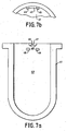
- the bowl 41 includes, on its inner surface 43 two spaced apart flanges 45 and a third flange 47 having a notch 49.
- a filter cartridge 51 having a flange 53 is first positioned so that flange 53 is positioned between flange 47 and flanges 45 ( Fig. 7 c) .
- the cartridge 51 then is slid into the position shown in Fig. 7 d so that flange 53 having shoulder 55 is positioned so that shoulder 55 fits into notch 49 thereby retaining cartridge 51 on bowl 41.
- the top portion 57 of filter cartridge 59 having fluid outlet or inlet 61 which, in contradiction to the invention includes arms or flanges 65 which are snap fit into slots 67 within the inner surface periphery of a bowl 69.
- the bowl 69 and filter cartridge 59 can be seaied into a manifold (not shown) as a single unit.
- the flange 65 is provided with a wedge shaped element 70 secured to surface 71 and spaced apart from surface 72.
- a collar 80 is illustrated which is utilized in accordance with the invention in accordance with the invention in conjunction with a filter cartridge free of a flange which can be snap fit into a slot of a bowl as discussed above.
- the collar 80 provides the advantage that it can be removed from a used filter cartridge prior to discarding the used cartridge so that the collar 80 can be reused with a fresh filter cartridge.
- the collar 80 is provided with feed inlets 82 to the bowl 28 ( Fig. 16 ).
- the collar 80 attaches to a flange 87 of a filter cartridge 84.
- the collar 80 is provided with flanges 88 that are fit into slots of a bowl as described above.
- the design of the flanges can be of any design provided they produce the desired retention function.
- the collar 80 includes a hinge 81 so that a portion of it can be rotated to engage hook elements 83 and 85 to engage or disengage the collar 80 with or from the filter cartridge 84. Permeate is removed from the filter cartridge through outlet 86.
- FIGs 13, 14 and 15 an alternative collar construction is shown that includes two hinges 90 and 91 as well as mating hooks 92 and 93.
- the collar fits about the periphery of filter cartridge 94 which includes a permeate outlet 95.
- the flanges 96 fit into mating slots of a bowl as described above with reference to Fig. 16 .
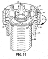
- Figs. 17 , 18 and 19 illustrate the installation and removal of the filtration module of this invention shown in with respect to the filter cartridge-bowl construction shown in Fig. 16 .
- the threads 38 of ring 34 are contacted with the threads 13 of manifold 37.
- the ring 34 then is rotated counterclockwise as illustrated by arrow 39 which moves the filter cartridge 26 and bowl 28 toward the manifold 37 until the filter cartridge 26 and bowl 28 are in the position relative to the manifold 37 shown in Fig. 18 .
- This relative movement is achieved by virtue of rotation of the ring 34 and because the ring 34 is supported by the rods 36.
- the filter cartridge 26 and bowl 28 move as a unit since the filter cartridge is locked into bowl 28 as described above with reference to Fig.
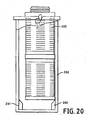
- Figure 20 shows another embodiment useful in the present invention.
- the cartridge is inserted into the bowl on an angle, such as is shown in Fig. 3 a to 3 h.
- One or more alignment fins 200 are formed on the lower inner surface 201 of the bowl 202. Those fins allow the cartridge 203 to be trued in a vertical alignment as it is piaced into the bowl 202.
- the number of fins 200 used preferably is at least from 2 to 6 with 3 being the most preferred.
- the fins 200 preferably are equally spaced from each other around the circumference of the inner surface 201. As shown the fins 200 are of a stepped configuration with the upper portion being on angle less than that of vertical and the lower portion being substantially vertical in orientation. This embodiment allows for the cartridge 203 to be easily inserted into the housing and rest adjacent the bottom of the housing. If desired, other arrangements of fins as to angle, length, height may be used and are not critical to the invention so long as they provide adequate mounting and demounting of the cartridge from the housing.
- the collar feature of the present invention as shown in Figures 10-12 may be comprised of a collar that contains no hinges. Such an embodiment is shown in Figure 4 .
- the collar 210 is simply snap-fit over the end of the cartridge portion 211 to which it is attached and held in place to the cartridge by the snap-fit design.
- the design of this embodiment or the embodiment of Figures 10-12 may use the flange as shown in Figures 10-12 or it may use a bayonet or lug 212 as shown in Figure 4 as the means for attaching the cartridge to the housing.
- the selection of the attachment means is not critical to the invention.
- Figure 5 shows the embodiment of Figure 4 in cross section as attached to the cartridge.
- Figure 6 shows a second embodiment of the snap fit design of Figures 4 and 5 wherein the portion which extends over and beyond the top of the cartridge is formed of two or more distinct portions 213 A-D.
- the media includes but is not limited to of flat sheet membrane, spiral wound flat sheet membrane, pleated flat sheet membrane, spiral pleated flat sheet membrane, hollow fiber membrane, depth filter media such as spiral wound continuous fiber depth filter media, sintered metal filter media, ceramic media, particulate media containing an active capture material such as resin or ceramic beads or a membrane with ligands for removing selected materials from the fluid attached to their surfaces, ion exchange media such as anion resin, cation resin or mixtures of the two alone or incorporated into a membrane structure and combinations of any of these.
- This media may be formed of any material typically used in filtration such as paper, other cellulosic materials such as regenerated celluloseor nitrocellulose, glass fiber and fabric, metal such as stainless steel, nickel, chromium and alloys and blends thereof, ceramics, plastics, preferably thermoplastic materials such as polyolefins, homopolymers, copolymers or terpolymers, including polyethylene such as ultrahigh molecular weight polyethylene, polypropylene and the like, PVDF, PTFE resin, PFA, ECTFE and other fluorinated resins, particularly perfluorinated thermoplastic resins, PVC, nylons, polyamides, polysulphones, modified polysulphones such as polyethersulphones, polyarylsulphones and polyphenylsulphones, polyimides, polycarbonates, PET and the like.
- thermoplastic materials such as polyolefins, homopolymers, copolymers or terpolymers, including polyethylene such as ultrahigh molecular
- the bowl and manifold may be made of a plastic, preferably a thermoplastic including polyolefins such as polyethylene, ultrahigh molecular weight polyethylene or polypropylene, copolymers or terpolymers of polyolefins, nylons, PTFE resin, PFA, PVDF, ECTFE and other fluorinated resins, particularly perfluorinated thermoplastic resins, polycarbonates, polysulphones, modified polysulphones such as polyethersulphone, polyarylsulphones or polyphenylsulphones, any glass or other reinforced plastic or a metal such as stainless steel, aluminum, copper, bronze, brass, nickel, chromium or titanium or alloys or blends thereof.
- polyolefins such as polyethylene, ultrahigh molecular weight polyethylene or polypropylene, copolymers or terpolymers of polyolefins, nylons, PTFE resin, PFA, PVDF, ECTFE and other fluorinated resins, particularly per
Landscapes
- Chemical & Material Sciences (AREA)
- Chemical Kinetics & Catalysis (AREA)
- Separation Using Semi-Permeable Membranes (AREA)
Claims (7)
- Filtrationsmodul, das umfaßt:einen Verteiler, eine Filterkartusche (84;94;211) und einen Behälter (28), welcher die Filterkartusche aufnimmt,wobei die Filterkartusche einen Kragen (80;210) umfaßt, der sich radial um den Umfang der Filterkartusche (84;94;211) erstreckt und entfernbar an der Filterkartusche angebracht ist,wobei der Behälter (28) und die Filterkartusche miteinander verbunden sind, um einen einheitlichen Aufbau zu bilden, indem der Kragen (80;210) an einer Innenseitenwand des Behälters (28) mittels eines Rastsitzes befestigt ist, undwobei die Filterkartusche (84;94;211) und der Behälter (28) in Fluidverbindung mit dem Verteiler auf eine Weise stehen, die ein Vermischen einer Fluidzufuhr zu der Filterkartusche mit einem aus der Filterkartusche entfernten Permeat verhindert.
- Filtrationsmodul gemäß Anspruch 1, wobei der Behälter (28) Schlitze (40) besitzt, die an einer Innenoberfläche des Behälters (28) ausgebildet sind, und der Kragen (80) Flansche (88) besitzt, die mit einem Rastsitz in die Schlitze (40) des Behälters (28) eingreifen, wenn die Filterkartusche in dem Behälter eingesetzt ist bzw. wird.
- Filtrationsmodul gemäß Anspruch 1 oder 2, das einen Einlaß (82) für eine Fluidzufuhr zu dem Behälter und einen Auslaß (86;95) für Permeat von der Filterkartusche umfaßt.
- Filtrationsmodul gemäß Anspruch 1 oder 2, das einen Einlaß für Fluidzufuhr zu der Filterkartusche und einen Auslaß für Permeat aus dem Behälter umfaßt.
- Filtrationsmodul gemäß Anspruch 1, 2, 3 oder 4, wobei der Kragen (80) ein Gelenk (81;90;91) zum Anbringen des Kragens (80) an der Filterkartusche (84;94) umfaßt.
- Filtrationsmodul gemäß Anspruch 1, 2, 3 oder 4, wobei der Kragen (210) an der Kartusche (211) durch eine Rastsitzverbindung angebracht ist.
- Filtrationsmodul gemäß einem der Ansprüche 1 bis 6, wobei die Filterkartusche ein oder mehrere Filtermedien enthält, die aus der Gruppe ausgewählt sind, die aus einer flachlagigen Membran, einer spiralförmig gewickelten flachlagigen Membran, einer gefältelten flachlagigen Membran, einer spiralförmig gefältelten flachlagigen Membran, einer Hohlfasermembran, Tiefenfiltermedien, ein aktives Auffangmaterial enthaltenden Teilchenmedien, Ionenaustauschmedien und Kombinationen hiervon gebildet ist.
Applications Claiming Priority (3)
| Application Number | Priority Date | Filing Date | Title |
|---|---|---|---|
| US10364698P | 1998-10-09 | 1998-10-09 | |
| US103646P | 1998-10-09 | ||
| EP99949906A EP1119403B1 (de) | 1998-10-09 | 1999-09-28 | Filterpatrone und gehäuse mit rastverbindung |
Related Parent Applications (2)
| Application Number | Title | Priority Date | Filing Date |
|---|---|---|---|
| EP99949906A Division EP1119403B1 (de) | 1998-10-09 | 1999-09-28 | Filterpatrone und gehäuse mit rastverbindung |
| EP99949906.4 Division | 1999-09-28 |
Publications (2)
| Publication Number | Publication Date |
|---|---|
| EP1498169A1 EP1498169A1 (de) | 2005-01-19 |
| EP1498169B1 true EP1498169B1 (de) | 2010-06-16 |
Family
ID=33477692
Family Applications (1)
| Application Number | Title | Priority Date | Filing Date |
|---|---|---|---|
| EP04007588A Expired - Lifetime EP1498169B1 (de) | 1998-10-09 | 1999-09-28 | Filtrationsmodul |
Country Status (1)
| Country | Link |
|---|---|
| EP (1) | EP1498169B1 (de) |
Families Citing this family (1)
| Publication number | Priority date | Publication date | Assignee | Title |
|---|---|---|---|---|
| US20210260533A1 (en) * | 2019-02-14 | 2021-08-26 | Her Majesty The Queen In Right Of Canada As Represented By The Minister Of Natural Resources | Method for fouling reduction on the surface of ceramic membranes using steam fast-flushing |
Citations (1)
| Publication number | Priority date | Publication date | Assignee | Title |
|---|---|---|---|---|
| DE19527844A1 (de) * | 1995-07-29 | 1997-01-30 | Knecht Filterwerke Gmbh | Radial durchströmbares Ringfilterelement |
Family Cites Families (3)
| Publication number | Priority date | Publication date | Assignee | Title |
|---|---|---|---|---|
| GB2222534B (en) * | 1988-09-09 | 1992-11-25 | Process Scient Innovations | Filter assembly and cartridge therefor |
| DE29623867U1 (de) * | 1995-03-16 | 2000-05-25 | Hengst Walter Gmbh & Co Kg | Filterelement für einen Flüssigkeitsfilter mit Filterumgehungsventil und filterelementseitiger Dichtfläche |
| US5814215A (en) * | 1995-06-17 | 1998-09-29 | Knecht Filterwerke Gmbh | Oil filter including an integral filter support and housing drain valve assembly |
-
1999
- 1999-09-28 EP EP04007588A patent/EP1498169B1/de not_active Expired - Lifetime
Patent Citations (1)
| Publication number | Priority date | Publication date | Assignee | Title |
|---|---|---|---|---|
| DE19527844A1 (de) * | 1995-07-29 | 1997-01-30 | Knecht Filterwerke Gmbh | Radial durchströmbares Ringfilterelement |
Also Published As
| Publication number | Publication date |
|---|---|
| EP1498169A1 (de) | 2005-01-19 |
Similar Documents
| Publication | Publication Date | Title |
|---|---|---|
| US6533933B1 (en) | Filtration module including unitary filter cartridge-bowl construction | |
| US8070945B2 (en) | Filtration module including unitary filter cartridge-bowl construction | |
| US6635175B2 (en) | Filter housing | |
| US20040182777A1 (en) | Filtration module including unitary filter cartridge-bowl construction | |
| US7520984B2 (en) | Filter cartridge construction | |
| US7169302B2 (en) | Filter cartridge construction | |
| US6830683B2 (en) | Filter cartridge assembly with brine seal and retaining ring | |
| US20040159600A1 (en) | Filtration module including unitary filter cartridge-bowl construction | |
| EP1901825B1 (de) | Filtrationsmodul | |
| EP0948387B1 (de) | Eingekapseltes linsenförmiges patronenfilter | |
| US20030141235A1 (en) | Filtration module including unitary filter cartridge-bowl construction | |
| WO2003002229A1 (en) | Filtration module including unitary filter cartridge-bowl construction | |
| EP1498169B1 (de) | Filtrationsmodul | |
| AU729705B2 (en) | Encapsulated lenticular filter cartridge |
Legal Events
| Date | Code | Title | Description |
|---|---|---|---|
| PUAI | Public reference made under article 153(3) epc to a published international application that has entered the european phase |
Free format text: ORIGINAL CODE: 0009012 |
|
| 17P | Request for examination filed |
Effective date: 20040329 |
|
| AC | Divisional application: reference to earlier application |
Ref document number: 1119403 Country of ref document: EP Kind code of ref document: P |
|
| AK | Designated contracting states |
Kind code of ref document: A1 Designated state(s): DE ES FR GB IT NL |
|
| AKX | Designation fees paid |
Designated state(s): DE ES FR GB IT NL |
|
| RAP1 | Party data changed (applicant data changed or rights of an application transferred) |
Owner name: ENTEGRIS, INC. |
|
| 17Q | First examination report despatched |
Effective date: 20071220 |
|
| GRAP | Despatch of communication of intention to grant a patent |
Free format text: ORIGINAL CODE: EPIDOSNIGR1 |
|
| GRAS | Grant fee paid |
Free format text: ORIGINAL CODE: EPIDOSNIGR3 |
|
| GRAA | (expected) grant |
Free format text: ORIGINAL CODE: 0009210 |
|
| AC | Divisional application: reference to earlier application |
Ref document number: 1119403 Country of ref document: EP Kind code of ref document: P |
|
| AK | Designated contracting states |
Kind code of ref document: B1 Designated state(s): DE ES FR GB IT NL |
|
| REF | Corresponds to: |
Ref document number: 69942511 Country of ref document: DE Date of ref document: 20100729 Kind code of ref document: P |
|
| REG | Reference to a national code |
Ref country code: NL Ref legal event code: T3 |
|
| REG | Reference to a national code |
Ref country code: ES Ref legal event code: FG2A Ref document number: 2345252 Country of ref document: ES Kind code of ref document: T3 |
|
| PGFP | Annual fee paid to national office [announced via postgrant information from national office to epo] |
Ref country code: DE Payment date: 20100929 Year of fee payment: 12 |
|
| PGFP | Annual fee paid to national office [announced via postgrant information from national office to epo] |
Ref country code: IT Payment date: 20100927 Year of fee payment: 12 |
|
| PLBE | No opposition filed within time limit |
Free format text: ORIGINAL CODE: 0009261 |
|
| STAA | Information on the status of an ep patent application or granted ep patent |
Free format text: STATUS: NO OPPOSITION FILED WITHIN TIME LIMIT |
|
| 26N | No opposition filed |
Effective date: 20110317 |
|
| REG | Reference to a national code |
Ref country code: DE Ref legal event code: R097 Ref document number: 69942511 Country of ref document: DE Effective date: 20110316 |
|
| PGFP | Annual fee paid to national office [announced via postgrant information from national office to epo] |
Ref country code: FR Payment date: 20111005 Year of fee payment: 13 Ref country code: ES Payment date: 20110926 Year of fee payment: 13 Ref country code: GB Payment date: 20110926 Year of fee payment: 13 |
|
| PGFP | Annual fee paid to national office [announced via postgrant information from national office to epo] |
Ref country code: NL Payment date: 20110929 Year of fee payment: 13 |
|
| REG | Reference to a national code |
Ref country code: NL Ref legal event code: V1 Effective date: 20130401 |
|
| GBPC | Gb: european patent ceased through non-payment of renewal fee |
Effective date: 20120928 |
|
| REG | Reference to a national code |
Ref country code: FR Ref legal event code: ST Effective date: 20130531 |
|
| PG25 | Lapsed in a contracting state [announced via postgrant information from national office to epo] |
Ref country code: DE Free format text: LAPSE BECAUSE OF NON-PAYMENT OF DUE FEES Effective date: 20130403 Ref country code: GB Free format text: LAPSE BECAUSE OF NON-PAYMENT OF DUE FEES Effective date: 20120928 |
|
| PG25 | Lapsed in a contracting state [announced via postgrant information from national office to epo] |
Ref country code: IT Free format text: LAPSE BECAUSE OF NON-PAYMENT OF DUE FEES Effective date: 20120928 Ref country code: FR Free format text: LAPSE BECAUSE OF NON-PAYMENT OF DUE FEES Effective date: 20121001 Ref country code: NL Free format text: LAPSE BECAUSE OF NON-PAYMENT OF DUE FEES Effective date: 20130401 |
|
| REG | Reference to a national code |
Ref country code: DE Ref legal event code: R119 Ref document number: 69942511 Country of ref document: DE Effective date: 20130403 |
|
| REG | Reference to a national code |
Ref country code: ES Ref legal event code: FD2A Effective date: 20131022 |
|
| PG25 | Lapsed in a contracting state [announced via postgrant information from national office to epo] |
Ref country code: ES Free format text: LAPSE BECAUSE OF NON-PAYMENT OF DUE FEES Effective date: 20120929 |