EP1498006B1 - Optical switching station and connection method for the same - Google Patents
Optical switching station and connection method for the same Download PDFInfo
- Publication number
- EP1498006B1 EP1498006B1 EP03720346A EP03720346A EP1498006B1 EP 1498006 B1 EP1498006 B1 EP 1498006B1 EP 03720346 A EP03720346 A EP 03720346A EP 03720346 A EP03720346 A EP 03720346A EP 1498006 B1 EP1498006 B1 EP 1498006B1
- Authority
- EP
- European Patent Office
- Prior art keywords
- switching
- input
- output
- wavelength
- cross connect
- Prior art date
- Legal status (The legal status is an assumption and is not a legal conclusion. Google has not performed a legal analysis and makes no representation as to the accuracy of the status listed.)
- Expired - Lifetime
Links
- 230000003287 optical effect Effects 0.000 title claims description 40
- 238000000034 method Methods 0.000 title claims description 5
- 238000004891 communication Methods 0.000 claims description 13
- 238000007493 shaping process Methods 0.000 claims description 8
- 238000006243 chemical reaction Methods 0.000 claims description 6
- 239000004744 fabric Substances 0.000 claims 23
- 239000011159 matrix material Substances 0.000 description 40
- 230000003750 conditioning effect Effects 0.000 description 8
- 230000008929 regeneration Effects 0.000 description 8
- 238000011069 regeneration method Methods 0.000 description 8
- 239000013307 optical fiber Substances 0.000 description 6
- 238000003491 array Methods 0.000 description 2
- 230000005540 biological transmission Effects 0.000 description 2
- 238000010586 diagram Methods 0.000 description 2
- 230000003321 amplification Effects 0.000 description 1
- 238000010276 construction Methods 0.000 description 1
- 238000001514 detection method Methods 0.000 description 1
- 238000005516 engineering process Methods 0.000 description 1
- 238000003780 insertion Methods 0.000 description 1
- 230000037431 insertion Effects 0.000 description 1
- 230000001404 mediated effect Effects 0.000 description 1
- 238000003199 nucleic acid amplification method Methods 0.000 description 1
- 230000001172 regenerating effect Effects 0.000 description 1
Images

Classifications
-
- H—ELECTRICITY
- H04—ELECTRIC COMMUNICATION TECHNIQUE
- H04Q—SELECTING
- H04Q11/00—Selecting arrangements for multiplex systems
- H04Q11/0001—Selecting arrangements for multiplex systems using optical switching
- H04Q11/0005—Switch and router aspects
-
- H—ELECTRICITY
- H04—ELECTRIC COMMUNICATION TECHNIQUE
- H04Q—SELECTING
- H04Q11/00—Selecting arrangements for multiplex systems
- H04Q11/0001—Selecting arrangements for multiplex systems using optical switching
- H04Q11/0005—Switch and router aspects
- H04Q2011/0007—Construction
- H04Q2011/0011—Construction using wavelength conversion
-
- H—ELECTRICITY
- H04—ELECTRIC COMMUNICATION TECHNIQUE
- H04Q—SELECTING
- H04Q11/00—Selecting arrangements for multiplex systems
- H04Q11/0001—Selecting arrangements for multiplex systems using optical switching
- H04Q11/0005—Switch and router aspects
- H04Q2011/0007—Construction
- H04Q2011/0016—Construction using wavelength multiplexing or demultiplexing
-
- H—ELECTRICITY
- H04—ELECTRIC COMMUNICATION TECHNIQUE
- H04Q—SELECTING
- H04Q11/00—Selecting arrangements for multiplex systems
- H04Q11/0001—Selecting arrangements for multiplex systems using optical switching
- H04Q11/0005—Switch and router aspects
- H04Q2011/0007—Construction
- H04Q2011/002—Construction using optical delay lines or optical buffers or optical recirculation
-
- H—ELECTRICITY
- H04—ELECTRIC COMMUNICATION TECHNIQUE
- H04Q—SELECTING
- H04Q11/00—Selecting arrangements for multiplex systems
- H04Q11/0001—Selecting arrangements for multiplex systems using optical switching
- H04Q11/0005—Switch and router aspects
- H04Q2011/0007—Construction
- H04Q2011/0024—Construction using space switching
Definitions
- the present invention relates to the field of optical communication, and more particularly to an optical switching station and a method of switching a message signal in an optical switching station.
- Optical switching stations serve as nodes of optical networks. They are connected in pairs with each other by optical fibers, on which message signals in the form of modulated light signals are transmitted from one switching station to another.
- An optical fiber can transmit a large number of message signals simultaneously in the form of modulated carrier waves of different wavelengths, respectively.
- an optical network that uses wavelength division multiplexing
- the substation of Fig. 1 (a) of this document has a plurality of switching arrays Tuning filters are used as demultiplexers for distributing the individual message signals to the switching matrices, suggesting that a given wavelength component of an incoming wavelength division multiplex may be forwarded to different switching matrices In the switching station of Fig.
- the demultiplexed message signals are all communicated over a single switching matrix which obviously must be able to handle different wavelengths
- the number of S The switch in such a switching matrix is very high, since each input must be connectable to each output.
- the object of the invention is to provide an optical switching station and a method for switching a message signal in an optical switching station, which allow a wavelength conversion with little technical effort.
- an optical switching station having a first plurality of through-traffic input channels, a second plurality of through-traffic output channels, a plurality of first optical switching arrays comprising a first group of input ports connected to the input channels of the switching station, and a first group of output terminals connected to the output channels of the switching station, for interconnecting input and output channels with each other, and a group of one or more waveform shaping units configured as wavelength converters, and means for connecting a second group of output terminals first optical switching matrices each having an input of a signal conditioning unit of the group and means for connecting a second group of input terminals of the first optical switching matrices each having an output of these signal conditioning units, wherein the first switching matrices are respectively provided for switching message signals of a same, associated with the respective first switching matrix wavelength and the means are suitable for connection, the input and the output of a Wavelength converter to connect each with different first switching matrices.
- This optical switching station allows a message signal, which can not be directly output to an output channel, because the desired output channel is occupied by the wavelength of the relevant message signal, to be switched through to an output terminal of the second group, so that the message signal can be subjected to the required wavelength conversion and then supplying the shaped signal to an input terminal of the second group of a first optical switching matrix, from where the respective first switching matrix is able to forward this signal to the originally desired output terminal.
- hardwired lines can be provided between an output or input of a signal conditioning unit and an input and output terminal of the first switching matrix.
- the means for connecting may also be formed as switching elements for selectively connecting an output or input of a signal conditioning unit to one of a plurality of input terminals of the first switching matrix.
- the switching station comprises a plurality of first switching matrices in order to adapt the signal conditioning units as needed to be able to assign the plurality of first switching matrices.
- Such switching elements are particularly desirable when the signal conditioning units are wavelength converters, not all of which are necessarily capable of generating all the wavelengths transmitted on the input and output channels, and which should therefore always be connectable to those first switching matrices which there is a need for such a wavelength converter.
- the means for connecting preferably comprise at least a second switching matrix, which connects the output terminals of the second group of the first switching matrices optionally with one of the wavelength converters.
- This makes it possible to use simple wavelength converters that are sensitive in a wide wavelength interval that encompasses all wavelengths of the multiplex, but that can only transmit this multiplex at a single wavelength.
- the second switching matrix is helpful in order to connect each message signal whose carrier wavelength has to be converted to the exactly required wavelength converter, regardless of at which output terminal of which first switching matrix the signal to be converted is output.
- the means for connecting further comprises at least a third switching matrix selectively connecting the wavelength converters to one of the input terminals of the second group of first switching matrices.
- the third switching matrix enables dynamic allocation of the wavelength converters to different input terminals of the second group, so that not every one of these input terminals must have a fixed wavelength converter.
- the wavelength converters can be assigned to different input terminals as needed, it is not necessary to assign a separate wavelength converter to each of these input terminals, and the number of wavelength converters required is reduced.
- each input channel is connected to the first switching matrices via a wavelength demultiplexer and / or the first switching matrices to the output channel via a wavelength multiplexer connected.
- a wavelength demultiplexer and / or the first switching matrices to the output channel via a wavelength multiplexer connected.
- the inputs and outputs of the second group can be used not only for supplying the signal conditioning units, but also for locally branching or adding message signals from or into the multiplex.
- the wavelength converters used are those having a wavelength-tunable transmitter part. Although these are technically more complicated than wavelength converter with fixed-frequency transmitter part, but only a smaller number of them is required to achieve a given level of availability.
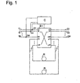
- the switching station shown in Fig. 1 comprises a single switching matrix S1 with input terminals i1, i2, ..., iM, i'1, ..., i'P and output terminals o1, o2, ..., oM, o'1 , ..., o'P.
- a first group i1, ..., iM of the input terminals is connected to input channels I1, ..., IM, here in the form of a respective fixed-frequency message signal leading optical fibers.
- a first group o1, ..., oM of the output terminals is connected to monochromatic output channels o1, ..., OM.
- Output terminals o'1, ..., o'P are respectively connected via regenerators R to input terminals i'1, ..., i'P hardwired via optical fibers f.
- a control circuit C receives, in a manner known per se and not shown here, routing information which, for each of the input terminals i1 to iM, determines to which of the output terminals o1, oM of the first group it is to be connected.
- the control circuit C is further connected to detectors D1, D2,..., DM arranged in front of each input terminal i1, i2,..., IM of the first group for detecting the quality of a message signal arriving at the input terminal.
- the control circuit C controls the switching matrix S1 differently from the routing information supplied thereto, the signal at the input terminal i2 this message signal is output to an output terminal of the second group, for example, the output terminal o'1.
- the message signal thus passes through one of the regenerators R and reenters the switching matrix S1 at the input terminal i'1.
- This input terminal i'1 is now connected to the output terminal provided according to the routing information as the output terminal for the message signal.
- the message signal to be regenerated thus passes through the switching matrix S1 twice, before or after the regeneration.
- Message signals where it is determined that regeneration is not required pass through switch matrix S1 only once.
- the power losses experienced by these communication signals in the switching station are the same (neglecting any losses due to the detectors D1, ..., Dn) as in a substation without regeneration function.
- the substation allows so a selective regeneration without insertion loss on non-regenerated message signals.
- the switching matrix S1 processes only message signals of the same wavelength, each resulting from different input channels.
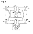
- a configuration as shown in Fig. 2 is preferable for the transmission of wavelength division multiplexed message signals.
- Fig. 2 shows a switching station with regeneration function for a wavelength division multiplexed optical network.
- the input channels I1, ..., IM are each here from an (not shown) remote switching station coming optical fibers on which a multiplex of transmitted to different carrier wavelengths ⁇ 1, ..., ⁇ N message signals is transmitted.
- the input channels each lead to wavelength demultiplexers D1, ..., DM, which spectrally decompose the multiplex and distribute the message signals contained therein N switching matrices S1, ..., SN, each one of the wavelengths ⁇ 1, ..., ⁇ N assigned.
- These switching matrices S1,..., SN respectively correspond to the monochromatic switching matrix S1 of FIG.
- each output terminal of the first group o1, ..., oM is a wavelength multiplexer M1, ..., MM with N inputs, one for each switching matrix s1, ..., SN, connected, which superimposes the received from the various switching matrices message signals of different wavelengths to a multiplexed signal and outputs to an output channel O1, ..., OM.
- Detectors for detecting the signal quality are also provided here on the line sections connected to the demultiplexers with the switching matrices, but they are, just like the control circuit, not shown for the sake of clarity.
- the mode of operation of the individual switching matrices is the same as in the case of FIG.
- collisions may occur when a switching matrix of two demultiplexers receives message signals destined for the same output channel. Namely, only one output terminal is available at the switching matrix leading to the desired output channel. In such a situation, only one of the two signals can be switched.
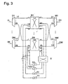
- Fig. 3 shows a block diagram of a switching station according to the invention which solves this problem.
- Input and output channels, multiplexers, demultiplexers and switching matrices S1, ..., SN are the same as in the embodiment of Fig. 2 and will not be explained again.
- the output terminals o'1, ..., o'P of the second group of switching matrices S1, ..., SN are fed to input terminals of a further optical switching matrix S ', whose output terminals are in turn connected to inputs of wavelength converters T1, T2, ... , TQ are connected.
- the wavelength converters here each comprise a photodiode which is sensitive to all wavelengths ⁇ 1,..., ⁇ N and converts the optical message signal coming from the switching matrix S 'into an electrical signal, electrical circuits for pulse shaping and amplification connected thereto and one with the Output signal of these electrical circuits controlled Fixed wavelength laser diode providing the regenerated optical message signal.
- the wavelength converters T1, T2,..., TQ thus also have a regeneration function at the same time.
- the output of each wavelength converter is connected by an optical fiber piece f hardwired to an input terminal of the second group of the switching matrix S1,... Or SN associated with its wavelength.
- the switch matrix S ' is able to couple all its input and output ports in pairs at random.
- a message signal to be formed can thus be fed via the matrix S 'to a wavelength converter with any desired output wavelength of the multiplex, including the current wavelength of the message signal. This latter case corresponds to a simple regeneration of the message signal without simultaneous wavelength conversion.
- the switching matrices S1, ..., SN are shown here with two input and output terminals of the second group, but it is obvious that the number of these connections between 1 and M can be selected arbitrarily.
- Fig. 4 shows a further developed embodiment of the switching station.
- the switching station of FIG. 4 differs from that of FIG. 3 in that, in the former, the wavelength converters T1,..., TQ comprise a laser diode instead of a fixed-wavelength laser diode which is sensitive to the different wavelengths .lambda.1, the multiplex or at least a plurality of these wavelengths is tunable.
- a third switching matrix S is present between the outputs of the wavelength converters T1,..., TQ and
- the number of tunable wavelength converters needed to achieve a given level of security against wavelength collisions in the substation is less than that of the second set of switch matrices S1, ..., SN Embodiment of Fig. 3 with fixed-frequency wavelength converters.
- second and third switching matrix S ', S " are also useful to branch message signals at the location of the switching station itself to receivers RX or feed from transmitters TX.
Description
Die vorliegende Erfindung betrifft das Gebiet der optischen Nachrichtenübertragung und zwar insbesondere eine optische Schaltstation und ein Verfahren zum Vermitteln eines Nachrichtensignals in einer optischen Schaltstation.The present invention relates to the field of optical communication, and more particularly to an optical switching station and a method of switching a message signal in an optical switching station.
Optische Schaltstationen dienen als Knoten von optischen Netzwerken. Sie sind paarweise untereinander durch optische Fasern verbunden, auf denen Nachrichtensignale in Form modulierter Lichtsignale von einer Schaltstation zur anderen übertragen werden. Eine optische Faser kann eine große Zahl von Nachrichtensignalen gleichzeitig jeweils in Form von modulierten Trägerwellen mit unterschiedlicher Wellenlänge übertragen.Optical switching stations serve as nodes of optical networks. They are connected in pairs with each other by optical fibers, on which message signals in the form of modulated light signals are transmitted from one switching station to another. An optical fiber can transmit a large number of message signals simultaneously in the form of modulated carrier waves of different wavelengths, respectively.
Bei einem optischen Netzwerk, das mit Wellenlängenmultiplex arbeitet, ist es wünschenswert, in einer Schaltstation Nachrichtensignale, die auf unterschiedlichen Trägerwellenlängen eines gleichen Multiplex moduliert sind, unabhängig voneinander vermitteln zu können. Es kann daher zu Situationen kommen, wo zwei Nachrichtensignale, die an einer optischen Schaltstation über verschiedene Eingangskanäle eintreffen und die gleiche Trägerwellenlänge haben, an einen gleichen Ausgangskanal vermittelt werden sollen. Es ist jedoch nicht möglich, beide Nachrichtensignale mit der gleichen Trägerwellenlänge auf dem gleichen Ausgangskanal zu übertragen. Daher benötigen die optischen Schaltstationen in einem solchen optischen Netzwerk Wellenlängenwandler, die es erlauben, die Wellenlänge eines dieser beiden Nachrichtensignale auf eine auf dem Ausgangskanal noch unbelegte Wellenlänge zu verschieben. Zwei Beispiele für eine solche Schaltstation sind in R. Sabella et al. "Impact of Transmission Performance on Path Routing in All-Optical Transport Networks", EEE Journal of Lightwave Technology, Vol. 16, p. 1965 et seq., 1998, beschrieben. Die Schaltstation aus Fig. 1(a) dieses Dokuments weist eine Mehrzahl von Schaltmatrizen auf, von denen jede einen mit einem Block von Wellenlängenwandlern verbundenen Ausgang und Eingang hat. Als Demultiplexer zum Verteilen der einzelnen Nachrichtensignale auf die Schaltmatrizen dienen abstimmbare Filter, was vermuten lässt, dass eine gegebene Wellenlängenkomponente eines eintreffenden Wellenlängenmultiplex an verschiedene Schaltmatrizen weitergeleitet werden kann. Bei der Schaltstation aus Fig. 1(b) dieses Dokuments werden die gedemultiplexten Nachrichtensignale sämtlich über eine einzige Schaltmatrix vermittelt, die offensichtlich in der Lage sein muss, unterschiedliche Wellenlängen zu verarbeiten. Es gibt mehrere Wellenlängenwandler, die jeweils einen Ausgang mit einem Eingang der Schaltmatrix verbinden. Die Zahl der Schalter in einer solchen Schaltmatrix ist sehr hoch, da jeder Eingang mit jedem Ausgang verbindbar sein muss.In an optical network that uses wavelength division multiplexing, it is desirable to be able to independently communicate message signals modulated on different carrier wavelengths of a same multiplex in a switching station. Therefore, situations may arise where two message signals arriving at an optical switching station via different input channels and having the same carrier wavelength are to be switched to a same output channel. However, it is not possible to transmit both message signals with the same carrier wavelength on the same output channel. Therefore, the optical switching stations in such an optical network require wavelength converters which allow the wavelength of one of these two message signals to be shifted to a wavelength still unused on the output channel. Two examples of such a switching station are described in R. Sabella et al. "Impact of Transmission Performance on Path Routing in All-Optical Transport Networks ", EEE Journal of Lightwave Technology, Vol 16, p.1655 et seq., 1998. The substation of Fig. 1 (a) of this document has a plurality of switching arrays Tuning filters are used as demultiplexers for distributing the individual message signals to the switching matrices, suggesting that a given wavelength component of an incoming wavelength division multiplex may be forwarded to different switching matrices In the switching station of Fig. 1 (b) of this document, the demultiplexed message signals are all communicated over a single switching matrix which obviously must be able to handle different wavelengths There are several wavelength converters each connecting one output to an input of the switch matrix The number of S The switch in such a switching matrix is very high, since each input must be connectable to each output.
Aufgabe der Erfindung ist, eine optische Schaltstation und ein Verfahren zum Vermitteln eines Nachrichtensignals in einer optischen Schaltstation anzugeben, die eine Wellenlängenkonversion mit geringem technischen Aufwand ermöglichen.The object of the invention is to provide an optical switching station and a method for switching a message signal in an optical switching station, which allow a wavelength conversion with little technical effort.
Die Aufgabe wird zum einen gelöst durch eine optische Schaltstation mit einer ersten Mehrzahl von Eingangskanälen für Durchgangsdatenverkehr, einer zweiten Mehrzahl von Ausgangskanälen für Durchgangsdatenverkehr, einer Mehrzahl von ersten optischen Schaltmatrizen, die eine erste Gruppe von Eingangsanschlüssen, die mit den Eingangskanälen der Schaltstation verbunden sind, und eine erste Gruppe von Ausgangsanschlüssen, die mit den Ausgangskanälen der Schaltstation verbunden sind, aufweist, zum Verbinden von Eingangs- und Ausgangskanälen untereinander, und einer Gruppe von einer oder mehreren als Wellenlängenwandler ausgebildeten Signalformereinheiten, sowie mit Mitteln zum Verbinden einer zweiten Gruppe von Ausgangsanschlüssen der ersten optischen Schaltmatrizen mit jeweils einem Eingang einer Signalformereinheit der Gruppe und Mitteln zum Verbinden einer zweiten Gruppe von Eingangsanschlüssen der ersten optischen Schaltmatrizen mit jeweils einem Ausgang dieser Signalformereinheiten, wobei die ersten Schaltmatrizen jeweils zum Schalten von Nachrichtensignalen einer gleichen, der betreffenden ersten Schaltmatrix zugeordneten Wellenlänge vorgesehen sind und die Mittel zum Verbinden geeignet sind, den Eingang und den Ausgang eines Wellenlängenwandlers mit jeweils verschiedenen ersten Schaltmatrizen zu verbinden. Diese optische Schaltstation erlaubt es, ein Nachrichtensignal, das nicht unmittelbar auf einen Ausgangskanal ausgegeben werden kann, weil auf dem gewünschten Ausgangskanal die Wellenlänge des betreffenden Nachrichtensignals besetzt ist, auf einen Ausgangsanschluss der zweiten Gruppe durchzuschalten, so dass das Nachrichtensignal der benötigten Wellenlängenwandlung unterzogen werden kann, und anschließend das geformte Signal einem Eingangsanschluss der zweiten Gruppe einer ersten optischen Schaltmatrix zuzuführen, von wo aus die betreffende erste Schaltmatrix dieses Signal zum ursprünglich gewünschten Ausgangsanschluss weiterleiten kann.The object is achieved on the one hand by an optical switching station having a first plurality of through-traffic input channels, a second plurality of through-traffic output channels, a plurality of first optical switching arrays comprising a first group of input ports connected to the input channels of the switching station, and a first group of output terminals connected to the output channels of the switching station, for interconnecting input and output channels with each other, and a group of one or more waveform shaping units configured as wavelength converters, and means for connecting a second group of output terminals first optical switching matrices each having an input of a signal conditioning unit of the group and means for connecting a second group of input terminals of the first optical switching matrices each having an output of these signal conditioning units, wherein the first switching matrices are respectively provided for switching message signals of a same, associated with the respective first switching matrix wavelength and the means are suitable for connection, the input and the output of a Wavelength converter to connect each with different first switching matrices. This optical switching station allows a message signal, which can not be directly output to an output channel, because the desired output channel is occupied by the wavelength of the relevant message signal, to be switched through to an output terminal of the second group, so that the message signal can be subjected to the required wavelength conversion and then supplying the shaped signal to an input terminal of the second group of a first optical switching matrix, from where the respective first switching matrix is able to forward this signal to the originally desired output terminal.
Als Mittel zum Verbinden der Signalformereinheiten mit einer der ersten optischen Schaltmatrix können fest verdrahtete Leitungen zwischen einem Ausgang oder Eingang einer Signalformereinheit und einem Eingangs- bzw. Ausgangsanschluss der ersten Schaltmatrix vorgesehen werden.As means for connecting the signal conditioning units to one of the first optical switching matrix, hardwired lines can be provided between an output or input of a signal conditioning unit and an input and output terminal of the first switching matrix.
Die Mittel zum Verbinden können jedoch auch als Schaltelemente zum wahlweisen Verbinden eines Ausgangs oder Eingangs einer Signalformereinheit mit einem von mehreren Eingangs- ' bzw. Ausgangsanschlüssen der ersten Schaltmatrix ausgebildet sein. Dies ist insbesondere dann zweckmäßig, wenn die Schaltstation eine Mehrzahl von ersten Schaltmatrizen umfasst, um die Signalformereinheiten je nach Bedarf einer der mehreren ersten Schaltmatrizen zuordnen zu können. Derartige Schaltelemente sind insbesondere auch dann wünschenswert, wenn die Signalformereinheiten Wellenlängenwandler sind, von denen nicht notwendigerweise jeder in der Lage ist, sämtliche auf den Ein- und Ausgangskanälen übertragenen Wellenlängen zu erzeugen, und die daher zweckmäßigerweise immer mit denjenigen ersten Schaltmatrizen verbindbar sein sollten, bei denen Bedarf nach einem solchen Wellenlängenwandler besteht.However, the means for connecting may also be formed as switching elements for selectively connecting an output or input of a signal conditioning unit to one of a plurality of input terminals of the first switching matrix. This is expedient in particular when the switching station comprises a plurality of first switching matrices in order to adapt the signal conditioning units as needed to be able to assign the plurality of first switching matrices. Such switching elements are particularly desirable when the signal conditioning units are wavelength converters, not all of which are necessarily capable of generating all the wavelengths transmitted on the input and output channels, and which should therefore always be connectable to those first switching matrices which there is a need for such a wavelength converter.
Die Mittel zum Verbinden umfassen vorzugsweise wenigstens eine zweite Schaltmatrix, die die Ausgangsanschlüsse der zweiten Gruppe der ersten Schaltmatrizen wahlweise mit einem der Wellenlängenwandler verbindet. Dies erlaubt es, einfache Wellenlängenwandler zu verwenden, die zwar in einem breiten Wellenlängenintervall empfindlich sind, welches alle Wellenlängen des Multiplex umfasst, die aber nur auf einer einzigen Wellenlänge dieses Multiplex senden können. Hier ist die zweite Schaltmatrix hilfreich, um jedes Nachrichtensignal, dessen Trägerwellenlänge gewandelt werden muss, mit dem genau benötigten Wellenlängenwandler zu verbinden, egal, an welchem Ausgangsanschluss welcher ersten Schaltmatrix das zu wandelnde Signal ausgegeben wird.The means for connecting preferably comprise at least a second switching matrix, which connects the output terminals of the second group of the first switching matrices optionally with one of the wavelength converters. This makes it possible to use simple wavelength converters that are sensitive in a wide wavelength interval that encompasses all wavelengths of the multiplex, but that can only transmit this multiplex at a single wavelength. Here, the second switching matrix is helpful in order to connect each message signal whose carrier wavelength has to be converted to the exactly required wavelength converter, regardless of at which output terminal of which first switching matrix the signal to be converted is output.
Vorzugsweise umfassen die Mittel zum Verbinden ferner wenigstens eine dritte Schaltmatrix, die die Wellenlängenwandler wahlweise mit einem der Eingangsanschlüsse der zweiten Gruppe der ersten Schaltmatrizen verbindet. Die dritte Schaltmatrix ermöglicht eine dynamische Zuordnung der Wellenlängenwandler zu verschiedenen Eingangsanschlüssen der zweiten Gruppe, so dass nicht jedem dieser Eingangsanschlüsse ein Wellenlängenwandler fest zugeordnet sein muss. Da die Wellenlängenwandler somit je nach Bedarf verschiedenen Eingangsanschlüssen zugeordnet werden können, ist es nicht notwendig, jedem dieser Eingangsanschlüsse einen eigenen Wellenlängenwandler zuzuordnen, und die Zahl der benötigten Wellenlängenwandler wird verringert.Preferably, the means for connecting further comprises at least a third switching matrix selectively connecting the wavelength converters to one of the input terminals of the second group of first switching matrices. The third switching matrix enables dynamic allocation of the wavelength converters to different input terminals of the second group, so that not every one of these input terminals must have a fixed wavelength converter. Thus, since the wavelength converters can be assigned to different input terminals as needed, it is not necessary to assign a separate wavelength converter to each of these input terminals, and the number of wavelength converters required is reduced.
Vorzugsweise ist jeder Eingangskanal mit den ersten Schaltmatrizen über einen Wellenlängen-Demultiplexer und/oder die ersten Schaltmatrizen mit dem Ausgangskanal über einen Wellenlängen-Multiplexer verbunden. Dies erlaubt die Nutzung der Eingangs- bzw. Ausgangskanäle im Wellenlängenmultiplex, wohingegen innerhalb der Schaltstation die Nachrichtensignale nach Wellenlängen getrennt gehandhabt werden.Preferably, each input channel is connected to the first switching matrices via a wavelength demultiplexer and / or the first switching matrices to the output channel via a wavelength multiplexer connected. This allows the use of the input and output channels in wavelength division multiplexing, whereas within the switching station the message signals are handled separately according to wavelengths.
Die Ein- und Ausgänge der zweiten Gruppe können nicht nur zum Versorgen der Signalformereinheiten genutzt werden, sondern auch zum lokalen Abzweigen oder Hinzufügen von Nachrichtensignalen aus dem bzw. in den Multiplex.The inputs and outputs of the second group can be used not only for supplying the signal conditioning units, but also for locally branching or adding message signals from or into the multiplex.
Vorzugsweise werden als Wellenlängenwandler solche mit einem wellenlängenabstimmbaren Senderteil eingesetzt. Diese sind zwar technisch aufwendiger als Wellenlängenwandler mit festfrequentem Senderteil, doch wird von ihnen auch nur eine geringere Anzahl benötigt, um ein gegebenes Maß an Verfügbarkeit zu erreichen.Preferably, the wavelength converters used are those having a wavelength-tunable transmitter part. Although these are technically more complicated than wavelength converter with fixed-frequency transmitter part, but only a smaller number of them is required to achieve a given level of availability.
Weitere Merkmale und Vorteile der Erfindung ergeben sich aus der nachfolgenden Beschreibung von Ausführungsbeispielen unter Bezugnahme auf die beigefügten Figuren. Es zeigen:
- Fig. 1
- ein Blockschältbild einer nicht erfindungsgemäßen optischen Schaltstation mit einer einzigen Schaltmatrix für den Betrieb bei einer einzigen Wellenlänge und mit Signalregeneratoren;
- Fig. 2
- eine weiterentwickelte Schaltstation mit Regeneratoren für Wellenlängenmultiplexbetrieb;
- Fig. 3
- eine erfindungsgemäße optische Schaltstation mit festfrequenten Wellenlängenwandlern; und
- Fig. 4
- eine erfindungsgemäße optische Schaltstation mit abstimmbaren Wellenlängenwandlern.
- Fig. 1
- a block diagram of a non-inventive optical switching station with a single switching matrix for operation at a single wavelength and with signal regenerators;
- Fig. 2
- an advanced substation with wavelength multiplexing regenerators;
- Fig. 3
- an optical switching station according to the invention with fixed-frequency wavelength converters; and
- Fig. 4
- an inventive optical switching station with tunable wavelength converters.
Die in Fig. 1 gezeigte Schaltstation umfasst eine einzige Schaltmatrix S1 mit Eingangsanschlüssen i1, i2, ..., iM, i'1, ..., i'P und Ausgangsanschlüssen o1, o2, ..., oM, o'1, ..., o'P. Eine erste Gruppe i1, ..., iM der Eingangsanschlüsse ist mit Eingangskanälen I1, ..., IM, hier in Form von jeweils ein festfrequentes Nachrichtensignal führenden optischen Fasern, verbunden. Entsprechend ist eine erste Gruppe o1, ..., oM der Ausgangsanschlüsse mit monochromatischen Ausgangskanälen o1, ..., OM verbunden. Ausgangsanschlüsse o'1, ..., o'P sind jeweils über Regeneratoren R mit Eingangsanschlüssen i'1, ..., i'P über optische Fasern f fest verdrahtet verbunden. Eine Steuerschaltung C empfängt in an sich bekannter und hier nicht dargestellter Weise Leitweginformation, die für jeden der Eingangsanschlüsse i1 bis iM festlegt, mit welchem der Ausgangsanschlüsse o1, oM der ersten Gruppe dieser verbunden werden soll. Die Steuerschaltung C ist ferner mit vor jedem Eingangsanschluss i1, i2, ..., iM der ersten Gruppe angeordneten Detektoren D1, D2, ..., DM zum Erfassen der Qualität eines an dem Eingangsanschluss eintreffenden Nachrichtensignals verbunden. Wenn das Erfassungsergebnis eines dieser Detektoren angibt, dass die Qualität zum Beispiel des Nachrichtensignals am Eingangsanschluss i2 schlecht ist und einer Regenerierung bedarf, so steuert die Steuerschaltung C die Schaltmatrix S1 abweichend von der ihr zugeführten, das Signal am Eingangsanschluss i2 betreffenden Leitweginformation so an, dass dieses Nachrichtensignal an einen Ausgangsanschluss der zweiten Gruppe, zum Beispiel den Ausgangsanschluss o'1, ausgegeben wird. So durchläuft das Nachrichtensignal einen der Regeneratoren R und tritt am Eingangsanschluss i'1 wieder in die Schaltmatrix S1 ein. Dieser Eingangsanschluss i'1 wird nun mit den der Leitweginformation zufolge als Ausgangsanschluss für das Nachrichtensignal vorgesehenen Ausgangsanschluss verbunden. Das zu regenerierende Nachrichtensignal durchläuft also die Schaltmatrix S1 zweimal, vor bzw. nach dem Regenerieren.The switching station shown in Fig. 1 comprises a single switching matrix S1 with input terminals i1, i2, ..., iM, i'1, ..., i'P and output terminals o1, o2, ..., oM, o'1 , ..., o'P. A first group i1, ..., iM of the input terminals is connected to input channels I1, ..., IM, here in the form of a respective fixed-frequency message signal leading optical fibers. Accordingly, a first group o1, ..., oM of the output terminals is connected to monochromatic output channels o1, ..., OM. Output terminals o'1, ..., o'P are respectively connected via regenerators R to input terminals i'1, ..., i'P hardwired via optical fibers f. A control circuit C receives, in a manner known per se and not shown here, routing information which, for each of the input terminals i1 to iM, determines to which of the output terminals o1, oM of the first group it is to be connected. The control circuit C is further connected to detectors D1, D2,..., DM arranged in front of each input terminal i1, i2,..., IM of the first group for detecting the quality of a message signal arriving at the input terminal. If the detection result of one of these detectors indicates that the quality of, for example, the message signal at the input terminal i2 is poor and requires regeneration, then the control circuit C controls the switching matrix S1 differently from the routing information supplied thereto, the signal at the input terminal i2 this message signal is output to an output terminal of the second group, for example, the output terminal o'1. The message signal thus passes through one of the regenerators R and reenters the switching matrix S1 at the input terminal i'1. This input terminal i'1 is now connected to the output terminal provided according to the routing information as the output terminal for the message signal. The message signal to be regenerated thus passes through the switching matrix S1 twice, before or after the regeneration.
Nachrichtensignale, bei denen festgestellt wird, dass keine Regenerierung erforderlich ist, durchlaufen die Schaltmatrix S1 nur einmal. Die Leistungsverluste, die diese Nachrichtensignale in der Schaltstation erfahren, sind (unter Vernachlässigung eventueller Verluste durch die Detektoren D1, ..., Dn) die gleichen wie bei einer Schaltstation ohne Regenerierungsfunktion. Die Schaltstation ermöglicht also eine selektive Regenerierung ohne Einfügungsverluste an nicht regenerierten Nachrichtensignalen.Message signals where it is determined that regeneration is not required pass through switch matrix S1 only once. The power losses experienced by these communication signals in the switching station are the same (neglecting any losses due to the detectors D1, ..., Dn) as in a substation without regeneration function. The substation allows so a selective regeneration without insertion loss on non-regenerated message signals.
Bei der Schaltstation der Fig. 1 verarbeitet die Schaltmatrix S1 nur Nachrichtensignale einer gleichen Wellenlänge, die jeweils von verschiedenen Eingangskanälen herrühren. Selbstverständlich ist es alternativ auch möglich, mehrere Nachrichtensignale im Wellenlängenmultiplex auf einem Eingangskanal zu befördern, sie über einen Demultiplexer verschiedenen Eingangsanschlüssen der Schaltmatrix zuzuführen und in der Schaltmatrix vermittelte Nachrichtensignale unterschiedlicher Wellenlänge über Multiplexer einem gemeinsamen Ausgangskanal zuzuführen. Da bei einem solchen Aufbau die Größe der Schaltmatrix mit dem Quadrat der Zahl der zu vermittelnden Signale anwächst, ist für die Vermittlung von wellenlängengemultiplexten Nachrichtensignalen ein Aufbau wie in Fig. 2 gezeigt bevorzugt.In the switching station of Fig. 1, the switching matrix S1 processes only message signals of the same wavelength, each resulting from different input channels. Of course, it is also alternatively possible to carry a plurality of message signals in wavelength division multiplex on an input channel, to supply them via a demultiplexer to different input terminals of the switching matrix and to supply in the switching matrix mediated message signals of different wavelengths via multiplexers to a common output channel. In such a construction, since the size of the switching matrix increases with the square of the number of signals to be switched, a configuration as shown in Fig. 2 is preferable for the transmission of wavelength division multiplexed message signals.
Fig. 2 zeigt eine Schaltstation mit Regenerierungsfunktion für ein optisches Netzwerk mit Wellenlängenmultiplexübertragung. Die Eingangskanäle I1, ..., IM sind hier jeweils von einer (nicht gezeigten) entfernten Schaltstation kommende optische Fasern, auf denen ein Multiplex von auf unterschiedliche Trägerwellenlängen λ1, ..., λN aufmodulierten Nachrichtensignalen übertragen wird. Die Eingangskanäle münden jeweils auf Wellenlängen-Demultiplexer D1, ..., DM, die den Multiplex spektral zerlegen und die darin enthaltenen Nachrichtensignale an N Schaltmatrizen S1, ..., SN verteilen, die jeweils einer der Wellenlängen λ1, ... , λN zugeordnet sind. Diese Schaltmatrizen S1, ..., SN entsprechen jeweils der monochromatischen Schaltmatrix S1 aus Fig. 1: sie haben eine erste Gruppe von Eingangsanschlüssen i1, ..., iM, die jeweils über einen der Demultiplexer D1, ..., DM mit einem der Eingangskanäle I1, IM verbunden sind, Eingangsanschlüsse i'1, ..., i'P, die jeweils mit dem Ausgang eines Regenerators R verbunden sind, Ausgangsanschlüsse o1, ..., oM einer ersten Gruppe und Ausgangsanschlüsse o'1 bis o'P, die jeweils mit den Eingängen der Regeneratoren R verbunden sind. An jeden Ausgangsanschluss der ersten Gruppe o1, ..., oM ist ein Wellenlängenmultiplexer M1, ..., MM mit je N Eingängen, einem für jede Schaltmatrix s1, ..., SN, angeschlossen, der die von den verschiedenen Schaltmatrizen empfangenen Nachrichtensignale unterschiedlicher Wellenlänge zu einem Multiplexsignal überlagert und auf einen Ausgangskanal O1, ..., OM ausgibt. Detektoren zum Erfassen der Signalqualität sind auch hier auf den die Demultiplexer mit den Schaltmatrizen verbundenen Leitungsstücken vorgesehen, doch sind sie, genauso wie die Steuerschaltung, der Übersichtlichkeit halber nicht dargestellt. Die Arbeitsweise der einzelnen Schaltmatrizen ist die gleiche wie im Falle der Fig. 1: nicht zu regenerierende Nachrichtensignale mit einer Trägerwellenlänge λn, n=1, ..., N durchlaufen die ihnen zugeordnete Schaltmatrix Sn einmal, ein zu regenerierendes Signal wird in der Schaltmatrix zu einem Regenerator R abgezweigt, und anschließend wird das regenerierte Signal in der gleichen Schaltmatrix an den vorgesehenen Ausgangskanal vermittelt.Fig. 2 shows a switching station with regeneration function for a wavelength division multiplexed optical network. The input channels I1, ..., IM are each here from an (not shown) remote switching station coming optical fibers on which a multiplex of transmitted to different carrier wavelengths λ1, ..., λN message signals is transmitted. The input channels each lead to wavelength demultiplexers D1, ..., DM, which spectrally decompose the multiplex and distribute the message signals contained therein N switching matrices S1, ..., SN, each one of the wavelengths λ1, ..., λN assigned. These switching matrices S1,..., SN respectively correspond to the monochromatic switching matrix S1 of FIG. 1: they have a first group of input terminals i1,..., IM, each with one of the demultiplexers D1, input terminals i'1, ..., i'P, which are respectively connected to the output of a regenerator R, output terminals o1, ..., oM of a first group and output terminals o'1 to o 'P, which are respectively connected to the inputs of the regenerators R. To each output terminal of the first group o1, ..., oM is a wavelength multiplexer M1, ..., MM with N inputs, one for each switching matrix s1, ..., SN, connected, which superimposes the received from the various switching matrices message signals of different wavelengths to a multiplexed signal and outputs to an output channel O1, ..., OM. Detectors for detecting the signal quality are also provided here on the line sections connected to the demultiplexers with the switching matrices, but they are, just like the control circuit, not shown for the sake of clarity. The mode of operation of the individual switching matrices is the same as in the case of FIG. 1: message signals not regenerating with a carrier wavelength λn, n = 1,..., N pass through the switching matrix Sn assigned to them once, a signal to be regenerated is in the switching matrix to a regenerator R, and then the regenerated signal in the same switching matrix is switched to the designated output channel.
Bei der Schaltstation der Fig. 2 können Kollisionen auftreten, wenn eine Schaltmatrix von zwei Demultiplexern Nachrichtensignale empfängt, die für den gleichen Ausgangskanal bestimmt sind. Es steht nämlich nur ein Ausgangsanschluss an der Schaltmatrix zur Verfügung, der zu dem gewünschten Ausgangskanal führt. In einer solchen Situation kann nur eines der zwei Signale vermittelt werden.In the switching station of Fig. 2, collisions may occur when a switching matrix of two demultiplexers receives message signals destined for the same output channel. Namely, only one output terminal is available at the switching matrix leading to the desired output channel. In such a situation, only one of the two signals can be switched.
Fig. 3 zeigt ein Blockdiagramm einer erfindungsgemäßen Schaltstation, die dieses Problem löst. Eingangs- und Ausgangskanäle, Multiplexer, Demultiplexer und Schaltmatrizen S1, ..., SN sind die gleichen wie bei der Ausgestaltung der Fig. 2 und werden nicht erneut erläutert. Die Ausgangsanschlüsse o'1, ..., o'P der zweiten Gruppe der Schaltmatrizen S1, ..., SN sind auf Eingangsanschlüsse einer weiteren optischen Schaltmatrix S' geführt, deren Ausgangsanschlüsse wiederum mit Eingängen von Wellenlängenwandlern T1, T2, ..., TQ verbunden sind. Die Wellenlängenwandler umfassen hier jeweils eine für alle Wellenlängen λ1, ..., λN des Multiplex empfindliche Fotodiode, die das von der Schaltmatrix S' kommende optische Nachrichtensignal in ein elektrisches Signal wandelt, daran angeschlossene elektrische Schaltungen zur Impulsformung und -verstärkung sowie eine mit dem Ausgangssignal dieser elektrischen Schaltungen angesteuerte Laserdiode mit fester Wellenlänge, die das regenerierte optische Nachrichtensignal liefert. Die Wellenlängenwandler T1, T2, ..., TQ haben somit gleichzeitig auch eine Regenerationsfunktion. Der Ausgang jedes Wellenlängenwandlers ist durch ein optisches Faserstück f fest verdrahtet mit einem Eingangsanschluss der zweiten Gruppe der seiner Wellenlänge zugeordneten Schaltmatrix S1, ..., oder SN verbunden.Fig. 3 shows a block diagram of a switching station according to the invention which solves this problem. Input and output channels, multiplexers, demultiplexers and switching matrices S1, ..., SN are the same as in the embodiment of Fig. 2 and will not be explained again. The output terminals o'1, ..., o'P of the second group of switching matrices S1, ..., SN are fed to input terminals of a further optical switching matrix S ', whose output terminals are in turn connected to inputs of wavelength converters T1, T2, ... , TQ are connected. The wavelength converters here each comprise a photodiode which is sensitive to all wavelengths λ1,..., ΛN and converts the optical message signal coming from the switching matrix S 'into an electrical signal, electrical circuits for pulse shaping and amplification connected thereto and one with the Output signal of these electrical circuits controlled Fixed wavelength laser diode providing the regenerated optical message signal. The wavelength converters T1, T2,..., TQ thus also have a regeneration function at the same time. The output of each wavelength converter is connected by an optical fiber piece f hardwired to an input terminal of the second group of the switching matrix S1,... Or SN associated with its wavelength.
Die Schaltmatrix S' ist in der Lage, alle ihre Eingangs- und Ausgangsanschlüsse wahlfrei paarweise miteinander zu verbinden. Ein zu formendes Nachrichtensignal kann somit über die Matrix S' einem Wellenlängenwandler mit jeder beliebigen Ausgangswellenlänge des Multiplex, einschließlich der gegenwärtigen Wellenlänge des Nachrichtensignals zugeführt werden. Dieser letztere Fall entspricht einer einfachen Regenerierung des Nachrichtensignals, ohne gleichzeitige Wellenlängenwandlung.The switch matrix S 'is able to couple all its input and output ports in pairs at random. A message signal to be formed can thus be fed via the matrix S 'to a wavelength converter with any desired output wavelength of the multiplex, including the current wavelength of the message signal. This latter case corresponds to a simple regeneration of the message signal without simultaneous wavelength conversion.
Die Schaltmatrizen S1, ..., SN sind hier mit jeweils zwei Eingangs- bzw. Ausgangsanschlüssen der zweiten Gruppe dargestellt, doch liegt auf der Hand, dass die Zahl dieser Anschlüsse zwischen 1 und M beliebig gewählt werden kann.The switching matrices S1, ..., SN are shown here with two input and output terminals of the second group, but it is obvious that the number of these connections between 1 and M can be selected arbitrarily.
Fig. 4 zeigt eine weiterentwickelte Ausgestaltung der Schaltstation. Die Schaltstation aus Fig. 4 unterscheidet sich von der der Fig. 3 dadurch, dass bei ersterer die Wellenlängenwandler T1, ..., TQ anstelle einer Laserdiode mit fester Wellenlänge eine Laserdiode enthalten, die auf die verschiedenen Wellenlängen λ1, ..., λN des Multiplex oder zumindest auf eine Mehrzahl dieser Wellenlängen abstimmbar ist. Um ein in einem solchen Wellenlängenwandler gewandeltes Nachrichtensignal an die der Wellenlänge des gewandelten Signals zugeordnete Matrix unter den Schaltmatrizen S1, ..., SN weiterleiten zu können, ist eine dritte Schaltmatrix S" zwischen den Ausgängen der Wellenlängenwandler T1, ..., TQ und den Eingangsanschlüssen der zweiten Gruppe der Schaltmatrizen S1, ..., SN erforderlich. Die Zahl der abstimmbaren Wellenlängenwandler, die benötigt wird, um ein vorgegebenes Maß an Sicherheit vor Wellenlängenkollisionen in der Schaltstation zu erreichen, ist kleiner als bei der Ausgestaltung der Fig. 3 mit festfrequenten Wellenlängenwandlern. Dabei ist die Einsparung um so größer, je größer die Zahl N der Wellenlängen des Multiplex ist. Daher kann eine Schaltstation nach Fig. 4 trotz der zusätzlichen Schaltmatrix und der aufwendigeren Wellenlängenwandler kompakter und preiswerter realisierbar sein als eine Schaltstation nach Fig. 3.Fig. 4 shows a further developed embodiment of the switching station. The switching station of FIG. 4 differs from that of FIG. 3 in that, in the former, the wavelength converters T1,..., TQ comprise a laser diode instead of a fixed-wavelength laser diode which is sensitive to the different wavelengths .lambda.1, the multiplex or at least a plurality of these wavelengths is tunable. In order to be able to forward a message signal converted in such a wavelength converter to the matrix assigned to the wavelength of the converted signal among the switching matrices S1,..., SN, a third switching matrix S "is present between the outputs of the wavelength converters T1,..., TQ and The number of tunable wavelength converters needed to achieve a given level of security against wavelength collisions in the substation is less than that of the second set of switch matrices S1, ..., SN Embodiment of Fig. 3 with fixed-frequency wavelength converters. The greater the number N of wavelengths of the multiplex, the greater the saving. Therefore, despite the additional switching matrix and the more expensive wavelength converter, a switching station according to FIG. 4 can be realized in a more compact and cheaper manner than a switching station according to FIG. 3.
Außerdem sind die zweite und dritte Schaltmatrix S', S" auch brauchbar, um Nachrichtensignale am Ort der Schaltstation selbst zu Empfängern RX abzuzweigen oder von Sendern TX einzuspeisen.In addition, the second and third switching matrix S ', S "are also useful to branch message signals at the location of the switching station itself to receivers RX or feed from transmitters TX.
Claims (11)
- An optical cross connect comprising:- a first plurality of input channels (I1, ..., IM) for transit data traffic,- a second plurality of output channels (O1, ..., OM) for transit data traffic,- a plurality of first optical switching fabrics (S1, ..., SN) comprising a first group of input ports (i1, i2, ..., iM) which are connected to input channels (I1, ..., IM) of the cross connect and a first group of output ports (o1, o2, ..., oM) which are connected to output channels (O1, ..., OM) of the cross connect, for interconnecting input and output channels,- a group of one or more signal shaping units (R; T1, ..., TQ; RX; SE, TX) formed as wavelength converters,- means (f, S') for connecting a second group of output ports (o'1, o'2, ..., o'P) of the first optical switching fabrics (S1, ..., SN) to a respective input of a signal shaping unit of the group and means (f, S") for connecting a second group (I' 1, ..., I"P) of input ports of the first optical switching fabrics (S1, ..., SN) to a respective output of one of said signal shaping units,characterized in that each of said first switching fabrics (S1, ..., SN) is provided for switching communication signals at a same wavelength assigned to said first switching fabric, and that the connecting means (S', f; S', S") are adapted to connect the input and the output of a wavelength converter (T1, ..., TQ) with different first switching fabrics (S1, ..., SN) .
- The optical cross connect of claim 1, characterized in that the connecting means comprise wired lines (f) between an output or input of the signal shaping unit and an input port or output port (i'1, ..., i'P; o'1, ..., o'P), respectively, of the first switching fabrics (S1, ..., SN).
- The cross connect of claim 1 or 2, characterized in that the connecting means comprise switching elements (S', S") for selectively connecting an output or an input of a signal shaping unit to one of several input or output ports, respectively, of the first switching fabrics.
- The optical cross connect according to one of the preceding claims, characterized in that each signal shaping unit (R, T1, ..., TQ) is adapted to shape an individual communication signal.
- The optical cross connect according to one of the preceding claims, characterized in that the connecting means comprise at least one second switching fabric (S') which selectively connects the second group output ports (o' 1, ..., o'P) of the first switching fabrics (S1, ..., SN) to one of the wavelength converters (T1, ..., TQ) .
- The optical cross connect according to one of the preceding claims, characterized in that the connecting means comprise at least a third switching fabric (S") which selectively connects the wavelength converters (T1, ..., TQ) to one of the second group input ports (i'1, ..., i'P) of the first switching fabrics (S1, ..., SN) .
- The optical cross connect according to one of the preceding claims, characterized in that each input channel (I1, ..., IM) is connected to the first switching fabrics (S1, ..., SN) via a wavelength demultiplexer (D1, ..., DM) and/or the first switching fabrics (S1, ..., SN) are connected to each output channel (O1, ..., OM) via a wavelength multiplexer (M1, ..., MM).
- The optical cross connect according to one of the preceding claims, characterized in that it comprises inputs and/or outputs (IM, OM) for branching data traffic and means (f, SE) for connecting these inputs or outputs to second group input or output ports (i'1, ..., i'P; o'1, ..., o'P) of the first switching fabrics (S1, ..., SN) .
- The optical cross connect according to one of the preceding claims, characterized in that the wavelength converters (T1, ..., TQ) each have a wavelength-tuneable transmitter part.
- The optical cross connect according to one of the preceding claims, characterized in that the first group input ports (i1, ..., iM) are connected to the input channels (I1, ..., IM) and/or the first group output ports (o1, ..., oM) are connected to the output channels (O1, ..., OM), respectively, without a switching fabric inserted in between.
- A method for switching a communication signal in an optical cross connect, in particular in an optical cross connect according to one of the preceding claims, the cross connect comprising a plurality of switching fabrics (S1, ..., SN) connected in parallel between a plurality of input channels and a plurality of output channels, each of the switching fabrics being provided for switching communication signals of a same wavelength assigned to it, comprising the steps of:a) receiving the communication signal by an input channel (I1, ..., IM) of the cross connect,b) assigning an output channel (O1, ..., OM) to the communication signal,c) deciding whether a wavelength conversion of the communication signal has to be carried out,d) inputting the communication signal into a switching fabric (S1, ..., SN) assigned to its wavelength,e) if a wavelength conversion was found necessary in step c):e1) outputting the signal at an output port (o'1, ..., o'P) of the switching fabric (S1, ..., SN) which is connected to a wavelength converter (T1, ..., TQ),e2) carrying out the wavelength conversion,e3) inputting the communication signal into another switching fabric from the plurality of parallel switching fabrics (S1, ..., SN), to which the converted wavelength of the communication signal is assigned,f) outputting the communication signal from the switching fabric (S1, ..., SN) to the output channel (O1, ..., OM) assigned to it.
Applications Claiming Priority (5)
| Application Number | Priority Date | Filing Date | Title |
|---|---|---|---|
| DE10213133A DE10213133A1 (en) | 2002-03-23 | 2002-03-23 | Optical switching station |
| DE10213133 | 2002-03-23 | ||
| DE10231275A DE10231275A1 (en) | 2002-07-10 | 2002-07-10 | Method for transmitting information in an optical network and nodes for such a network |
| PCT/EP2003/002998 WO2003081941A2 (en) | 2002-03-23 | 2003-03-22 | Optical switching station and connection method for the same |
| DE10231275 | 2003-07-10 |
Publications (2)
| Publication Number | Publication Date |
|---|---|
| EP1498006A2 EP1498006A2 (en) | 2005-01-19 |
| EP1498006B1 true EP1498006B1 (en) | 2006-06-07 |
Family
ID=28455535
Family Applications (1)
| Application Number | Title | Priority Date | Filing Date |
|---|---|---|---|
| EP03720346A Expired - Lifetime EP1498006B1 (en) | 2002-03-23 | 2003-03-22 | Optical switching station and connection method for the same |
Country Status (5)
| Country | Link |
|---|---|
| US (1) | US20060013586A1 (en) |
| EP (1) | EP1498006B1 (en) |
| CN (1) | CN100584101C (en) |
| DE (1) | DE50303699D1 (en) |
| WO (1) | WO2003081941A2 (en) |
Families Citing this family (8)
| Publication number | Priority date | Publication date | Assignee | Title |
|---|---|---|---|---|
| CN100388708C (en) * | 2005-01-01 | 2008-05-14 | 华为技术有限公司 | Grouped light channel sharing protection method and system |
| CN100454785C (en) * | 2005-12-22 | 2009-01-21 | 华为技术有限公司 | Method and apparatus for sharing protection of grouped light path |
| US7715711B2 (en) * | 2006-05-25 | 2010-05-11 | Fujitsu Limited | Wavelength selective switch design configurations for mesh light-trails |
| CN102264277B (en) * | 2008-07-09 | 2015-04-29 | 劳伦斯·M·麦金利 | Optic function monitoring process and apparatus |
| EP2549773B1 (en) * | 2011-07-21 | 2017-10-25 | Orange | Device and method for combining optical components associated with a wavelength in a combined optical component |
| CN104661117A (en) * | 2013-11-22 | 2015-05-27 | 华为技术有限公司 | Optical network switching equipment |
| CN103888857B (en) * | 2014-03-11 | 2018-06-19 | 北京邮电大学 | There is the node apparatus of shared modulation multiplex ability in the soft elastic optical switching network of definition |
| US10908369B1 (en) * | 2017-06-26 | 2021-02-02 | Amazon Technologies, Inc. | Flexible onboard optics for networking switches |
Family Cites Families (6)
| Publication number | Priority date | Publication date | Assignee | Title |
|---|---|---|---|---|
| JP2928046B2 (en) * | 1993-04-16 | 1999-07-28 | 日本電気株式会社 | Optical network and its fault recovery system |
| US6587240B1 (en) * | 1998-12-21 | 2003-07-01 | Agilent Technologies, Inc. | Optical switching node and method for operating same |
| EP1126650A3 (en) * | 2000-02-18 | 2007-01-03 | Ericsson AB | Optical communication system |
| AU4260701A (en) * | 2000-03-28 | 2001-10-08 | Ditech Communications Corporation | Routing device for all optical networks |
| US6999677B2 (en) * | 2000-11-30 | 2006-02-14 | Nortel Networks Limited | Protection switching arrangement for an optical switching system |
| US20030016410A1 (en) * | 2001-07-18 | 2003-01-23 | Innovance Networks | Method for engineering connections in a dynamically reconfigurable photonic switched network |
-
2003
- 2003-03-22 US US10/509,430 patent/US20060013586A1/en not_active Abandoned
- 2003-03-22 WO PCT/EP2003/002998 patent/WO2003081941A2/en active IP Right Grant
- 2003-03-22 DE DE50303699T patent/DE50303699D1/en not_active Expired - Lifetime
- 2003-03-22 CN CN03806831A patent/CN100584101C/en not_active Expired - Fee Related
- 2003-03-22 EP EP03720346A patent/EP1498006B1/en not_active Expired - Lifetime
Also Published As
| Publication number | Publication date |
|---|---|
| DE50303699D1 (en) | 2006-07-20 |
| EP1498006A2 (en) | 2005-01-19 |
| WO2003081941A2 (en) | 2003-10-02 |
| CN1643973A (en) | 2005-07-20 |
| CN100584101C (en) | 2010-01-20 |
| US20060013586A1 (en) | 2006-01-19 |
| WO2003081941A3 (en) | 2004-03-25 |
Similar Documents
| Publication | Publication Date | Title |
|---|---|---|
| DE69531848T2 (en) | Optical multiplexer with insert and hide channels | |
| DE69535053T2 (en) | Tunable optical insertion / branch method and apparatus | |
| DE19731494C2 (en) | Method and arrangement for data transmission using wavelength division multiplexing in an optical ring network | |
| DE60028551T2 (en) | Optical wavelength division multiplexed system with combined wavelength routing and routing of optical fibers | |
| DE60320044T2 (en) | PACKAGE AND OPTICAL GUIDANCE ARRANGEMENT AND METHOD | |
| EP1356619B1 (en) | Method and electro-optical circuit arrangement for line protection in a wdm data transmission link | |
| DE69533390T2 (en) | Network system without arbitration control and nodes for this network | |
| DE69938225T2 (en) | Cross-connection device and method for mediating and grouping channels | |
| EP1498006B1 (en) | Optical switching station and connection method for the same | |
| EP0972367B1 (en) | Access network for transmitting optical signals | |
| DE60212558T2 (en) | Optical TDM and WDM switching node | |
| DE10213133A1 (en) | Optical switching station | |
| EP1602188B1 (en) | Add-drop device and cross-connect device for wavelength multiplex signals | |
| WO2007048650A1 (en) | Add-drop-unit for wavelength division multiplex signals | |
| DE60307155T2 (en) | Multicast-capable crossconnect for optical signals | |
| DE60319788T2 (en) | Wavelength converter and optical cross connect system using the same | |
| DE10343615A1 (en) | Network node for an optical communications network | |
| EP1217867A2 (en) | Optical cross connect for arbitrary switching of communication signals from different multiplex planes | |
| DE10004290B4 (en) | Heat exchanger, has carrier for holding pipeline, where upper and lower carrier sections of carrier are formed from U-profile and turned towards each other with its rear side and connected with one another | |
| EP1997345A1 (en) | Wavelength-selective switch and method for channel-by-channel switching for a wavelength-selective switch | |
| DE69934058T2 (en) | Device for insertion and removal of a wavelength division multiplexed optical signal | |
| EP1121777A1 (en) | Optical unidirectional ring network | |
| EP1217869A2 (en) | Optical cross connect for arbitrary switching of communication signals from different multiplex planes | |
| EP3021506B1 (en) | Method and device for transparent switching of different DWDM systems with NxN AWGs | |
| EP1554832B1 (en) | Optical add/drop multiplexer and ring structure for transmitting data by means of an optical wavelength multiplex system |
Legal Events
| Date | Code | Title | Description |
|---|---|---|---|
| PUAI | Public reference made under article 153(3) epc to a published international application that has entered the european phase |
Free format text: ORIGINAL CODE: 0009012 |
|
| 17P | Request for examination filed |
Effective date: 20041021 |
|
| AK | Designated contracting states |
Kind code of ref document: A2 Designated state(s): AT BE BG CH CY CZ DE DK EE ES FI FR GB GR HU IE IT LI LU MC NL PT RO SE SI SK TR |
|
| GRAP | Despatch of communication of intention to grant a patent |
Free format text: ORIGINAL CODE: EPIDOSNIGR1 |
|
| GRAS | Grant fee paid |
Free format text: ORIGINAL CODE: EPIDOSNIGR3 |
|
| GRAA | (expected) grant |
Free format text: ORIGINAL CODE: 0009210 |
|
| AK | Designated contracting states |
Kind code of ref document: B1 Designated state(s): DE FR GB IT SE |
|
| PG25 | Lapsed in a contracting state [announced via postgrant information from national office to epo] |
Ref country code: IT Free format text: LAPSE BECAUSE OF FAILURE TO SUBMIT A TRANSLATION OF THE DESCRIPTION OR TO PAY THE FEE WITHIN THE PRESCRIBED TIME-LIMIT;WARNING: LAPSES OF ITALIAN PATENTS WITH EFFECTIVE DATE BEFORE 2007 MAY HAVE OCCURRED AT ANY TIME BEFORE 2007. THE CORRECT EFFECTIVE DATE MAY BE DIFFERENT FROM THE ONE RECORDED. Effective date: 20060607 Ref country code: GB Free format text: LAPSE BECAUSE OF FAILURE TO SUBMIT A TRANSLATION OF THE DESCRIPTION OR TO PAY THE FEE WITHIN THE PRESCRIBED TIME-LIMIT Effective date: 20060607 |
|
| REG | Reference to a national code |
Ref country code: GB Ref legal event code: FG4D Free format text: NOT ENGLISH |
|
| REF | Corresponds to: |
Ref document number: 50303699 Country of ref document: DE Date of ref document: 20060720 Kind code of ref document: P |
|
| PG25 | Lapsed in a contracting state [announced via postgrant information from national office to epo] |
Ref country code: SE Free format text: LAPSE BECAUSE OF FAILURE TO SUBMIT A TRANSLATION OF THE DESCRIPTION OR TO PAY THE FEE WITHIN THE PRESCRIBED TIME-LIMIT Effective date: 20060907 |
|
| REG | Reference to a national code |
Ref country code: GB Ref legal event code: 732E |
|
| GBV | Gb: ep patent (uk) treated as always having been void in accordance with gb section 77(7)/1977 [no translation filed] |
Effective date: 20060607 |
|
| PLBE | No opposition filed within time limit |
Free format text: ORIGINAL CODE: 0009261 |
|
| STAA | Information on the status of an ep patent application or granted ep patent |
Free format text: STATUS: NO OPPOSITION FILED WITHIN TIME LIMIT |
|
| EN | Fr: translation not filed | ||
| 26N | No opposition filed |
Effective date: 20070308 |
|
| PG25 | Lapsed in a contracting state [announced via postgrant information from national office to epo] |
Ref country code: FR Free format text: LAPSE BECAUSE OF FAILURE TO SUBMIT A TRANSLATION OF THE DESCRIPTION OR TO PAY THE FEE WITHIN THE PRESCRIBED TIME-LIMIT Effective date: 20070309 |
|
| PG25 | Lapsed in a contracting state [announced via postgrant information from national office to epo] |
Ref country code: FR Free format text: LAPSE BECAUSE OF FAILURE TO SUBMIT A TRANSLATION OF THE DESCRIPTION OR TO PAY THE FEE WITHIN THE PRESCRIBED TIME-LIMIT Effective date: 20060607 |
|
| PGFP | Annual fee paid to national office [announced via postgrant information from national office to epo] |
Ref country code: IT Payment date: 20150325 Year of fee payment: 13 Ref country code: DE Payment date: 20150327 Year of fee payment: 13 |
|
| REG | Reference to a national code |
Ref country code: DE Ref legal event code: R119 Ref document number: 50303699 Country of ref document: DE |
|
| PG25 | Lapsed in a contracting state [announced via postgrant information from national office to epo] |
Ref country code: DE Free format text: LAPSE BECAUSE OF NON-PAYMENT OF DUE FEES Effective date: 20161001 |
|
| PG25 | Lapsed in a contracting state [announced via postgrant information from national office to epo] |
Ref country code: IT Free format text: LAPSE BECAUSE OF NON-PAYMENT OF DUE FEES Effective date: 20160322 |