EP1497794B1 - Calibration software for surface reconstruction of small objects - Google Patents
Calibration software for surface reconstruction of small objects Download PDFInfo
- Publication number
- EP1497794B1 EP1497794B1 EP03721688A EP03721688A EP1497794B1 EP 1497794 B1 EP1497794 B1 EP 1497794B1 EP 03721688 A EP03721688 A EP 03721688A EP 03721688 A EP03721688 A EP 03721688A EP 1497794 B1 EP1497794 B1 EP 1497794B1
- Authority
- EP
- European Patent Office
- Prior art keywords
- rotation
- axis
- point
- rotary stage
- coordinate
- Prior art date
- Legal status (The legal status is an assumption and is not a legal conclusion. Google has not performed a legal analysis and makes no representation as to the accuracy of the status listed.)
- Expired - Lifetime
Links
- 238000005259 measurement Methods 0.000 claims description 15
- 230000009466 transformation Effects 0.000 claims description 15
- 238000000034 method Methods 0.000 claims description 12
- 239000011159 matrix material Substances 0.000 claims description 7
- 239000013598 vector Substances 0.000 claims description 6
- 238000004519 manufacturing process Methods 0.000 description 2
- 230000006978 adaptation Effects 0.000 description 1
- 238000010276 construction Methods 0.000 description 1
- 238000007796 conventional method Methods 0.000 description 1
- 230000000694 effects Effects 0.000 description 1
- 238000009472 formulation Methods 0.000 description 1
- 238000003384 imaging method Methods 0.000 description 1
- 238000012417 linear regression Methods 0.000 description 1
- 239000000203 mixture Substances 0.000 description 1
- 230000003287 optical effect Effects 0.000 description 1
- 238000011084 recovery Methods 0.000 description 1
- 238000000844 transformation Methods 0.000 description 1
Images

Classifications
-
- G—PHYSICS
- G06—COMPUTING; CALCULATING OR COUNTING
- G06T—IMAGE DATA PROCESSING OR GENERATION, IN GENERAL
- G06T7/00—Image analysis
- G06T7/70—Determining position or orientation of objects or cameras
Definitions
- the present invention relates to a method for determining an axis of rotation of a rotary stage as can be used for the reconstruction and recovery of the three-dimensional shape of an imaged object in a gauge measurement system, and robust and accurate estimation of the motion of a measured object mounted on a rotary stage.
- a gauge measurement system such as a non-contact optical measurement system or coordinate measuring machine (CMM)
- CCM coordinate measuring machine
- a rotary stage or platform is a mounting apparatus which is constrained to permit only movement about a single axis.
- Multiple views or contact measurements of the object are obtained by imaging or contacting the object at different poses.
- a calibration process is then utilized to provide a means to coherently merge the data taken at those views or measurements (recorded in local coordinate systems) into a single global coordinate system.
- the axis of rotation is fixed such that any object mounted to the rotary stage or platform is constrained to rotate about the same identified axis.
- Li et al. "A reverse engineering system for rapid manufacturing of complex objects” Robotics and Computer Integrated Manufacturing, Pergamon Press, Oxford, GB, vol. 18, no. 1, February 2002, pages 53 - 67 , discloses a vision-based coordinate measuring machine where multiple views of an object on a turntable are captured. For each view, point clouds are reconstructed from range images obtained via fringe pattern projection. These point clouds are registered and rigid body transformations between them are decomposed into a translation part and a rotation part. The registered patches are then used for modelling and rapid prototyping.
- the present invention provides a method for determining the axis of rotation of an object mounted to a rotary stage or platform in a gauge measurement system by estimating a transformation between multiple views or measurements of the object obtained at different poses as defined in independant claim 1.
- the present invention provides a method for determining the axis of rotation of a rotary stage or platform using a known calibration object and a robust registration scheme.
- a Robust Closest Patch (RCP) scheme is utilized to estimate the transformation between multiple poses of the object being measured.
- RCP Robust Closest Patch
- ICP iterative closest patch
- the known calibration object is designed in conjunction with the type of sensor undergoing calibration. Specifically, when mounted on the rotary stage or platform 10, a large area of the calibration object 12 must be visible to a camera based sensor or accessible to a contact based sensor in a wide range of poses or positions, without being occluded.
- the calibration object 12 is preferably centered at the suited-point of the sensor and should be large enough to cover the working volume of the sensor, as the accuracy of the calibration will increase with the average arm length of the calibration object 12, as measured from the center of rotation. To avoid reducing available information identifying the pose of the calibration object 12, it is preferred that the calibration object 12 not be round, and include a multiple number of large facets to avoid aliasing effects. Further, the facets are either visible to a camera based sensor or accessible to a contact sensor.
- Each pose of the calibration object 12 in a sequence is defined as P 1 , P 2 , ..., P k , ..., P n .
- the angle of rotation is preferably selected to be small enough to enforce a small amount of overlap between succeeding poses of the calibration object 12. From the data for P k and P k-1 , the transformation ⁇ can be estimated independently using the RCP algorithm or any other registration scheme.
- the direction of the axis of rotation is extracted from the estimated rotation by computing the quaternion equivalent of the rotation matrix.
- a point in an ( i , j, k ) coordinate system such as the camera coordinate system, can be transformed into a ( u , v , ⁇ ) coordinate system wherein the ⁇ -axis is parallel to the axis of rotation of the rotary stage 10.
- the center of rotation i.e.
- ⁇ A ⁇ ⁇
- A is the rotation from the coordinate system C' to C.
- condition cos ⁇ ⁇ 1 is utilized to avoid the identity transform which is a particular rotation that does not yield any axis of rotation.
- the rotary stage or platform 10 is likely to be imperfect, hence the parameter t z is exploited to check the planarity of the motion of the rotary stage or platform, and any t z ⁇ 0 it is set to zero.
- the transformation is represented as a matrix with coordinate points represented as vectors.
- the direction of the axis of rotation AR and the point T on the axis of rotation AR are invariant to the various parts of the transformation process.
- the direction of the axis of rotation AR is an eigenvector corresponding to an eigenvalue of +1.0 of the rotation R since it is invariant to the rotation.
- the point T on the axis of rotation AR is invariant to the transformation, and thus is an eigenvector corresponding to an eigenvalue of +1.0 of the [R
- An alternative formulation is that there must be two eigenvectors of [R
Landscapes
- Engineering & Computer Science (AREA)
- Computer Vision & Pattern Recognition (AREA)
- Physics & Mathematics (AREA)
- General Physics & Mathematics (AREA)
- Theoretical Computer Science (AREA)
- Length Measuring Devices By Optical Means (AREA)
- Length Measuring Devices With Unspecified Measuring Means (AREA)
Description
- The present invention relates to a method for determining an axis of rotation of a rotary stage as can be used for the reconstruction and recovery of the three-dimensional shape of an imaged object in a gauge measurement system, and robust and accurate estimation of the motion of a measured object mounted on a rotary stage.
- Traditionally, in a gauge measurement system, such as a non-contact optical measurement system or coordinate measuring machine (CMM), an object to be measured is mounted on a rotary stage or platform. A rotary stage or platform is a mounting apparatus which is constrained to permit only movement about a single axis. Multiple views or contact measurements of the object are obtained by imaging or contacting the object at different poses. A calibration process is then utilized to provide a means to coherently merge the data taken at those views or measurements (recorded in local coordinate systems) into a single global coordinate system.
- Conventional calibrations processes utilize plane intersections to coherently merge local coordinate systems into a global coordinate system. In such processes, a known planar object is mounted on the rotary stage or platform, a series of range images or sets of contact measurements of the object are obtained at different positions of the rotary stage. The data points from each rotary position are each fitted to an associated plane using a simple linear regression scheme. Intersecting pairs of the planes form vectors in space parallel to the axis of rotation. Combining these intersecting vectors yields the axis of rotation. So long as the rotary stage or platform is rigidly secured in relation to the sensor, and the calibration of the sensor does not subsequently change, the axis of rotation is fixed such that any object mounted to the rotary stage or platform is constrained to rotate about the same identified axis.
- Li et al.: "A reverse engineering system for rapid manufacturing of complex objects" Robotics and Computer Integrated Manufacturing, Pergamon Press, Oxford, GB, vol. 18, no. 1, February 2002, pages 53 - 67, discloses a vision-based coordinate measuring machine where multiple views of an object on a turntable are captured. For each view, point clouds are reconstructed from range images obtained via fringe pattern projection. These point clouds are registered and rigid body transformations between them are decomposed into a translation part and a rotation part. The registered patches are then used for modelling and rapid prototyping.
- The precision and robustness of any rotational axis estimation scheme depends upon the amount of uncorrelated (useful) data input to the system. Accordingly, there is a need for a method to accurately estimate the axis of rotation for a rotary stage or platform from multiple views or measurements of an object which provides an increase in the amount of data input to the system.
- Briefly stated, the present invention provides a method for determining the axis of rotation of an object mounted to a rotary stage or platform in a gauge measurement system by estimating a transformation between multiple views or measurements of the object obtained at different poses as defined in
independant claim 1. - The foregoing and other objects, features, and advantages of the invention as well as presently preferred embodiments thereof will become more apparent from the reading of the following description in connection with the accompanying drawings.
- In the accompanying drawings which form part of the specification:
-
Figure 1 is a perspective view of a calibration object mounted on a rotary stage at a first orientation; -
Figure 2 is a perspective view of the calibration object ofFigure 1 at a second orientation; -
Figure 3 is a perspective view of the calibration object ofFigure 1 at a third orientation; -
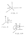
Figure 4 is a first coordinate system representation of the rotary stage axis of rotation; -
Figure 5 is a second coordinate system representation of the rotary stage axis of rotation; and -
Figure 6 is a representation of a coordinate transformation in three-dimensional space. - Corresponding reference numerals indicate corresponding parts throughout the several figures of the drawings.
- The following detailed description illustrates the invention by way of example and not by way of limitation. The description clearly enables one skilled in the art to make and use the invention, describes several embodiments, adaptations, variations, alternatives, and uses of the invention, including what is presently believed to be the best mode of carrying out the invention.
- The present invention provides a method for determining the axis of rotation of a rotary stage or platform using a known calibration object and a robust registration scheme. In one example, a Robust Closest Patch (RCP) scheme is utilized to estimate the transformation between multiple poses of the object being measured. Alternatively, an iterative closest patch (ICP) scheme, or other known scheme may be utilized to estimate the transformation between multiple poses of the
object 12. - The known calibration object is designed in conjunction with the type of sensor undergoing calibration. Specifically, when mounted on the rotary stage or
platform 10, a large area of thecalibration object 12 must be visible to a camera based sensor or accessible to a contact based sensor in a wide range of poses or positions, without being occluded. Thecalibration object 12 is preferably centered at the suited-point of the sensor and should be large enough to cover the working volume of the sensor, as the accuracy of the calibration will increase with the average arm length of thecalibration object 12, as measured from the center of rotation. To avoid reducing available information identifying the pose of thecalibration object 12, it is preferred that thecalibration object 12 not be round, and include a multiple number of large facets to avoid aliasing effects. Further, the facets are either visible to a camera based sensor or accessible to a contact sensor. - Each pose of the
calibration object 12 in a sequence is defined as P1, P2, ..., Pk, ..., Pn. Each pose of thecalibration object 12 differs from the previous pose by a constant rigid body increment δ, such that P2 = δP1, Pk = δPk-1, and Pn = δPn-1. The angle of rotation is preferably selected to be small enough to enforce a small amount of overlap between succeeding poses of thecalibration object 12. From the data for Pk and Pk-1, the transformation δ can be estimated independently using the RCP algorithm or any other registration scheme. - By combining all the data from each pose of the
calibration object 12 with the same set of constraints, and using the data for a joint estimation, a more accurate and stable solution for δ can be found. The transformation δ, as a rigid body transform, can be decomposed into a rotation R around the origin point, and a translation T:
where: - ω is the direction of the axis of rotation;
- θ is the angle of rotation; and
- t is the translation vector.
- The direction of the axis of rotation is extracted from the estimated rotation by computing the quaternion equivalent of the rotation matrix. Using a quaternion argument, a point in an (i, j, k) coordinate system, such as the camera coordinate system, can be transformed into a (u, v, ω) coordinate system wherein the ω-axis is parallel to the axis of rotation of the
rotary stage 10. To find a point (x, y, z)=Ω which is on the axis of rotation AR, it is known that any point on the axis of rotation AR will be rotated onto itself. The center of rotation, i.e. any point on the rotation axis, is determined as an invariant point, written using matrix notation as:
where Ω is the center of rotation. If Ω is transformed into the (u, v, ω) coordinate system, it is defined as Ω'=(x',y', z'), as is seen inFigures 4 and 5 . - To avoid the inversion of a singular matrix, and appropriate rotation is applied to the original three-dimensional space, which reduces the three-dimensional singular problem to a two-dimensional non-singular one.
- The original coordinate system for an image of the
calibration object 12 is defined as C = (i, j, k). Correspondingly, the rotated coordinate system for the object is defined as C' = (u, v, ω) where u, v, and ω form an orthogonal-normal basis, and ω is the unit vector along the axis of rotation AR. The center of rotation in the rotated space is given coordinates Ω', such that:
where A is the rotation from the coordinate system C' to C. Using a quaternion argument, it is possible to compute A such that a point in the (i, j, k) coordinate system can be transformed into the (u, v, ω) coordinate system. - Replacing equation (3) into equation (2), with results in:

where:

and R' is a rotation around the vertical axis. Equation (4) can be rewritten in matrix form as:
which has a solution if and only if t'z = 0 and cosθ ≠ 1. - The condition cosθ ≠ 1 is utilized to avoid the identity transform which is a particular rotation that does not yield any axis of rotation. The condition t z = 0 agrees with the geometrical intuition of pure rotation, i.e. the trajectories of points rigidly attached to a rotary stage under a rotation are arcs of circles in planes perpendicular to the axis of rotation, as seen in
Figure 6 . However, the rotary stage orplatform 10 is likely to be imperfect, hence the parameter t z is exploited to check the planarity of the motion of the rotary stage or platform, and any t z ≈ 0 it is set to zero. - Since t'x, t'y, and θ are known from the solutions to Eqn. 5 and Eqn. 6, it is possible to solve Eqn. 7 for x' and y' by assuming z' is any value. The assumption of z' having any value is valid, since z' merely represents the location of the point on the axis or rotation AR, and any point on the axis may be utilized. Solving the above system of equations yields the following analytical solutions:


Once x' and y' are identified, Eqn. 3 can be solved for the coordinates of point Ω on the axis of rotation AR. Since the direction of the axis of rotation AR is also known, the rotary stage is completely defined mathematically. - In one example, starting from the estimated transformation δ, the transformation is represented as a matrix with coordinate points represented as vectors. The direction of the axis of rotation AR and the point T on the axis of rotation AR are invariant to the various parts of the transformation process. In particular, the direction of the axis of rotation AR is an eigenvector corresponding to an eigenvalue of +1.0 of the rotation R since it is invariant to the rotation. Similarly, the point T on the axis of rotation AR is invariant to the transformation, and thus is an eigenvector corresponding to an eigenvalue of +1.0 of the [R | T - R*T] transformation. Those of ordinary skill in the art will recognize that there are numerous conventional techniques which may be employed to solve a matrix for eigenvectors having eigenvalues of 1.0, and which may be utilized to identify the direction of the axis of rotation AR and a point T on that axis given the estimated transform δ.
- An alternative formulation is that there must be two eigenvectors of [R |T - R*T] that have eignenvalues of +1. These two eigenvectors represent two points which are invariant to the transformation δ and hence are on the axis of rotation AR. Thus, and points on the axis of rotation AR are defiend as a linear combination of these two eigenvectors.
- In view of the above, it will be seen that the several objects of the invention are achieved and other advantageous results are obtained. As various changes could be made in the above constructions without departing from the scope of the invention, it is intended that all matter contained in the above description or shown in the accompanying drawings shall be interpreted as illustrative and not in a limiting sense.
Claims (3)
- A method for determining an axis of rotation (AR) of a rotary stage (10) upon which a calibration object (12) is rigidly mounted in a gauge measurement system including the rotary stage and a sensor, for calibrating the sensor, the method comprising:for each of a plurality of poses of said calibration object (12) incrementally rotated about said axis of rotation, obtaining a set of measurements representative of said pose, each of said poses differing from the previous pose by a constant rigid body increment δ;estimating, from sequential pairs of said sets of measurements, the rigid body transformation δ for the incremental rotation between each of said plurality of poses;decomposing said estimated rigid body transformation into an estimated rotation value and an estimated translation value; andestimating the axis of rotation from said rotation value and said translation value, including the step of identifying the coordinates of a point on the axis of rotation and wherein the point on the axis of rotation is identified in three-dimensional space relative to the rotary stage by:


wheret represents the translation vector;x' represents a coordinate of the point on the x' axis;y' represents a coordinate of the point on the y' axis;z' represents a coordinate of the point on the axis of rotation; andθ is the angle of incremental rotation,wherein the point on the axis of rotation is identified in three-dimensional space relative to the measurement system by solving:
whereΩ represents the three-dimensional coordinates of the point relative to the measurement system;Ω' represents the three-dimensional coordinates of the point relative to the rotary stage; andA represents a rotation from the rotary stage coordinate system to the measurement system coordinate system. - The method of Claim 1 for determining an axis of rotation of a rotary stage wherein estimating the axis of rotation from said rotation value includes computing the quaternion equivalent of a rotation matrix.
- The method of Claim 1 wherein said calibration object is comprised of multiple facets, each facet of said calibration object is visible to a camera based sensor or is accessible to a contact sensor.
Applications Claiming Priority (3)
| Application Number | Priority Date | Filing Date | Title |
|---|---|---|---|
| US10/063,362 US6615503B1 (en) | 2002-04-16 | 2002-04-16 | Calibration software for surface reconstruction of small objects |
| US63362 | 2002-04-16 | ||
| PCT/US2003/011658 WO2003090172A2 (en) | 2002-04-16 | 2003-04-16 | Calibration software for surface reconstruction of small objects |
Publications (2)
| Publication Number | Publication Date |
|---|---|
| EP1497794A2 EP1497794A2 (en) | 2005-01-19 |
| EP1497794B1 true EP1497794B1 (en) | 2010-03-10 |
Family
ID=27787424
Family Applications (1)
| Application Number | Title | Priority Date | Filing Date |
|---|---|---|---|
| EP03721688A Expired - Lifetime EP1497794B1 (en) | 2002-04-16 | 2003-04-16 | Calibration software for surface reconstruction of small objects |
Country Status (6)
| Country | Link |
|---|---|
| US (1) | US6615503B1 (en) |
| EP (1) | EP1497794B1 (en) |
| JP (1) | JP4445472B2 (en) |
| CN (1) | CN1303572C (en) |
| DE (1) | DE60331641D1 (en) |
| WO (1) | WO2003090172A2 (en) |
Families Citing this family (12)
| Publication number | Priority date | Publication date | Assignee | Title |
|---|---|---|---|---|
| SE0401408D0 (en) * | 2004-06-02 | 2004-06-02 | Astrazeneca Ab | Diameter measuring device |
| US7694427B2 (en) * | 2007-07-12 | 2010-04-13 | Long Fredrick D | Pipe fitting wireform for measuring linear distance and method |
| GB2464509C (en) * | 2008-10-17 | 2014-05-21 | Taylor Hobson Ltd | Surface measurement instrument and method |
| GB2499660B (en) * | 2012-02-27 | 2018-10-03 | Taylor Hobson Ltd | Surface measurement apparatus and method |
| EP2750107B1 (en) * | 2012-12-31 | 2017-03-15 | Dassault Systèmes | Groups of faces that form a geometrical pattern |
| EP2808810B1 (en) | 2013-05-28 | 2017-01-11 | Dassault Systèmes | Compression and decompression of 3d modeled object |
| EP3098734A1 (en) | 2015-05-28 | 2016-11-30 | Dassault Systèmes | Querying a database with likeness criterion |
| EP3098735A1 (en) | 2015-05-28 | 2016-11-30 | Dassault Systèmes | Querying a database with thickness criterion |
| DE102015226387B4 (en) * | 2015-12-21 | 2023-07-27 | Carl Zeiss Industrielle Messtechnik Gmbh | Procedure for performing measurements with a test element in a coordinate measuring machine or a machine tool |
| EP3264286B1 (en) | 2016-06-28 | 2020-11-18 | Dassault Systèmes | Querying a database with morphology criterion |
| EP3321817A1 (en) | 2016-11-14 | 2018-05-16 | Dassault Systèmes | Querying a database based on a parametric view function |
| US11281824B2 (en) | 2017-12-13 | 2022-03-22 | Dassault Systemes Simulia Corp. | Authoring loading and boundary conditions for simulation scenarios |
Family Cites Families (16)
| Publication number | Priority date | Publication date | Assignee | Title |
|---|---|---|---|---|
| US3237442A (en) * | 1963-01-21 | 1966-03-01 | Ford Motor Co | Apparatus for checking involute forms and method of operating same |
| JPS62168217U (en) * | 1986-04-16 | 1987-10-26 | ||
| US5589942A (en) | 1990-04-05 | 1996-12-31 | Intelligent Automation Systems | Real time three dimensional sensing system |
| US5359784A (en) * | 1991-05-02 | 1994-11-01 | Tokyo Seimitsu Co., Ltd. | Method of centering in roundness measuring instrument and system therefor |
| US5913820A (en) * | 1992-08-14 | 1999-06-22 | British Telecommunications Public Limited Company | Position location system |
| US5452521A (en) * | 1994-03-09 | 1995-09-26 | Niewmierzycki; Leszek | Workpiece alignment structure and method |
| NO300940B1 (en) * | 1994-09-26 | 1997-08-18 | Frantz Karsten Smith | Device for measuring torsion on rotating shafts |
| JP3095973B2 (en) * | 1995-03-24 | 2000-10-10 | ケイディディ株式会社 | Earth station position detection method in satellite communication system |
| US5621529A (en) | 1995-04-05 | 1997-04-15 | Intelligent Automation Systems, Inc. | Apparatus and method for projecting laser pattern with reduced speckle noise |
| JPH09120461A (en) * | 1995-10-25 | 1997-05-06 | Matsushita Electric Ind Co Ltd | Graphic editing device |
| JPH09123312A (en) * | 1995-10-31 | 1997-05-13 | Ashitani Takaaki | Automatic scales for regulating top of slitter |
| US6061468A (en) * | 1997-07-28 | 2000-05-09 | Compaq Computer Corporation | Method for reconstructing a three-dimensional object from a closed-loop sequence of images taken by an uncalibrated camera |
| DE19928482A1 (en) * | 1999-06-22 | 2000-12-28 | Bosch Gmbh Robert | Offset compensation of angle sensors involves representing offset to be compensated in co-ordinate system, relative to which measured sinusoidal and cosinusoidal value pairs lie on a circle |
| US6546640B2 (en) * | 2000-01-18 | 2003-04-15 | Mitutoyo Corporation | Traverse linearity compensation method and rotational accuracy compensation method of measuring device |
| KR100374783B1 (en) * | 2000-03-03 | 2003-03-04 | 학교법인 포항공과대학교 | Remote center compliance device with variable center |
| US6427856B1 (en) * | 2000-07-11 | 2002-08-06 | Trans World Marketing Corp. | Self-centering device for a rotating display |
-
2002
- 2002-04-16 US US10/063,362 patent/US6615503B1/en not_active Expired - Lifetime
-
2003
- 2003-04-16 WO PCT/US2003/011658 patent/WO2003090172A2/en active Application Filing
- 2003-04-16 CN CNB038084554A patent/CN1303572C/en not_active Expired - Fee Related
- 2003-04-16 DE DE60331641T patent/DE60331641D1/en not_active Expired - Lifetime
- 2003-04-16 JP JP2005518207A patent/JP4445472B2/en not_active Expired - Fee Related
- 2003-04-16 EP EP03721688A patent/EP1497794B1/en not_active Expired - Lifetime
Non-Patent Citations (1)
| Title |
|---|
| INTERNET PUBLICATION, 18 January 2001 (2001-01-18), Retrieved from the Internet <URL:http://prt.fernuni-hagen.de/lehre/KURSE/PRT001/course_main/node12.html> [retrieved on 20051006] * |
Also Published As
| Publication number | Publication date |
|---|---|
| CN1647112A (en) | 2005-07-27 |
| WO2003090172A8 (en) | 2004-02-19 |
| JP2006515422A (en) | 2006-05-25 |
| US6615503B1 (en) | 2003-09-09 |
| JP4445472B2 (en) | 2010-04-07 |
| DE60331641D1 (en) | 2010-04-22 |
| CN1303572C (en) | 2007-03-07 |
| EP1497794A2 (en) | 2005-01-19 |
| WO2003090172A3 (en) | 2003-12-24 |
| WO2003090172A2 (en) | 2003-10-30 |
Similar Documents
| Publication | Publication Date | Title |
|---|---|---|
| US9733339B2 (en) | Position and orientation calibration method and apparatus | |
| US8055466B2 (en) | Global calibration for stereo vision probe | |
| EP1497794B1 (en) | Calibration software for surface reconstruction of small objects | |
| US8731243B2 (en) | Position and orientation measurement method and position and orientation measurement apparatus | |
| US20020118892A1 (en) | Method and apparatus for image registration | |
| Shiu et al. | Finding the mounting position of a sensor by solving a homogeneous transform equation of the form AX= XB | |
| CN116433737A (en) | Method and device for registering laser radar point cloud and image and intelligent terminal | |
| US6611791B1 (en) | Method for combining partially measured data | |
| CN114136335A (en) | Aerial triangle precision analysis method based on unmanned aerial vehicle oblique photogrammetry | |
| Pless et al. | Extrinsic calibration of a camera and laser range finder | |
| CN111145267A (en) | IMU (inertial measurement unit) assistance-based 360-degree panoramic view multi-camera calibration method | |
| US20060020562A1 (en) | Apparatus and method for estimating optical flow | |
| Ruf et al. | Projective translations and affine stereo calibration | |
| Olague et al. | Hybrid evolutionary ridge regression approach for high-accurate corner extraction | |
| Dornaika | Self-calibration of a stereo rig using monocular epipolar geometries | |
| Kim et al. | An improved ICP algorithm based on the sensor projection for automatic 3D registration | |
| Pennec et al. | Registration of uncertain geometric features: Estimating the pose and its accuracy | |
| Viswanath et al. | A simplified error model for height estimation using a single camera | |
| CN113345029B (en) | Large-view-field reference plane calibration method in optical deflection three-dimensional measurement | |
| Ruf et al. | Projective translations and a ne stereo calibration | |
| KR20040094230A (en) | A method for automatic registration of 3D data using a projection matrix of a sensor | |
| CN117036619A (en) | Shoe upper point cloud acquisition device based on binocular vision and model generation method | |
| Horn | What is wrong with so-called’linear’photogrammetric methods? | |
| Serafinavičius | Investigation of technical equipment in computer stereo vision: camera calibration techniques | |
| CN117541493A (en) | Three-dimensional feature medical image fusion method based on improved fractional order cumulant |
Legal Events
| Date | Code | Title | Description |
|---|---|---|---|
| PUAI | Public reference made under article 153(3) epc to a published international application that has entered the european phase |
Free format text: ORIGINAL CODE: 0009012 |
|
| 17P | Request for examination filed |
Effective date: 20041116 |
|
| AK | Designated contracting states |
Kind code of ref document: A2 Designated state(s): AT BE BG CH CY CZ DE DK EE ES FI FR GB GR HU IE IT LI LU MC NL PT RO SE SI SK TR |
|
| GRAP | Despatch of communication of intention to grant a patent |
Free format text: ORIGINAL CODE: EPIDOSNIGR1 |
|
| GRAS | Grant fee paid |
Free format text: ORIGINAL CODE: EPIDOSNIGR3 |
|
| GRAA | (expected) grant |
Free format text: ORIGINAL CODE: 0009210 |
|
| AK | Designated contracting states |
Kind code of ref document: B1 Designated state(s): DE FR GB IT |
|
| REG | Reference to a national code |
Ref country code: GB Ref legal event code: FG4D |
|
| REF | Corresponds to: |
Ref document number: 60331641 Country of ref document: DE Date of ref document: 20100422 Kind code of ref document: P |
|
| PLBE | No opposition filed within time limit |
Free format text: ORIGINAL CODE: 0009261 |
|
| STAA | Information on the status of an ep patent application or granted ep patent |
Free format text: STATUS: NO OPPOSITION FILED WITHIN TIME LIMIT |
|
| 26N | No opposition filed |
Effective date: 20101213 |
|
| PG25 | Lapsed in a contracting state [announced via postgrant information from national office to epo] |
Ref country code: IT Free format text: LAPSE BECAUSE OF FAILURE TO SUBMIT A TRANSLATION OF THE DESCRIPTION OR TO PAY THE FEE WITHIN THE PRESCRIBED TIME-LIMIT Effective date: 20100310 |
|
| REG | Reference to a national code |
Ref country code: FR Ref legal event code: PLFP Year of fee payment: 13 |
|
| PGFP | Annual fee paid to national office [announced via postgrant information from national office to epo] |
Ref country code: DE Payment date: 20150429 Year of fee payment: 13 Ref country code: GB Payment date: 20150427 Year of fee payment: 13 |
|
| PGFP | Annual fee paid to national office [announced via postgrant information from national office to epo] |
Ref country code: FR Payment date: 20150417 Year of fee payment: 13 |
|
| REG | Reference to a national code |
Ref country code: DE Ref legal event code: R119 Ref document number: 60331641 Country of ref document: DE |
|
| GBPC | Gb: european patent ceased through non-payment of renewal fee |
Effective date: 20160416 |
|
| REG | Reference to a national code |
Ref country code: FR Ref legal event code: ST Effective date: 20161230 |
|
| PG25 | Lapsed in a contracting state [announced via postgrant information from national office to epo] |
Ref country code: FR Free format text: LAPSE BECAUSE OF NON-PAYMENT OF DUE FEES Effective date: 20160502 Ref country code: GB Free format text: LAPSE BECAUSE OF NON-PAYMENT OF DUE FEES Effective date: 20160416 Ref country code: DE Free format text: LAPSE BECAUSE OF NON-PAYMENT OF DUE FEES Effective date: 20161101 |