EP1497171B1 - Device for fastening emergency equipment to a ship s deck - Google Patents
Device for fastening emergency equipment to a ship s deck Download PDFInfo
- Publication number
- EP1497171B1 EP1497171B1 EP03723554A EP03723554A EP1497171B1 EP 1497171 B1 EP1497171 B1 EP 1497171B1 EP 03723554 A EP03723554 A EP 03723554A EP 03723554 A EP03723554 A EP 03723554A EP 1497171 B1 EP1497171 B1 EP 1497171B1
- Authority
- EP
- European Patent Office
- Prior art keywords
- fastening
- ship
- deck
- sleeve
- facility
- Prior art date
- Legal status (The legal status is an assumption and is not a legal conclusion. Google has not performed a legal analysis and makes no representation as to the accuracy of the status listed.)
- Expired - Lifetime
Links
- 239000000463 material Substances 0.000 claims description 2
- 238000010008 shearing Methods 0.000 description 24
- 238000010276 construction Methods 0.000 description 2
- 230000032683 aging Effects 0.000 description 1
- 230000007812 deficiency Effects 0.000 description 1
- 230000003292 diminished effect Effects 0.000 description 1
- 230000007257 malfunction Effects 0.000 description 1
- 238000000034 method Methods 0.000 description 1
- 239000002991 molded plastic Substances 0.000 description 1
- 239000004033 plastic Substances 0.000 description 1
- 229920003023 plastic Polymers 0.000 description 1
- 230000001681 protective effect Effects 0.000 description 1
- 229910001220 stainless steel Inorganic materials 0.000 description 1
- 230000003245 working effect Effects 0.000 description 1
Images


Classifications
-
- B—PERFORMING OPERATIONS; TRANSPORTING
- B63—SHIPS OR OTHER WATERBORNE VESSELS; RELATED EQUIPMENT
- B63C—LAUNCHING, HAULING-OUT, OR DRY-DOCKING OF VESSELS; LIFE-SAVING IN WATER; EQUIPMENT FOR DWELLING OR WORKING UNDER WATER; MEANS FOR SALVAGING OR SEARCHING FOR UNDERWATER OBJECTS
- B63C9/00—Life-saving in water
- B63C9/22—Devices for holding or launching life-buoys, inflatable life-rafts, or other floatable life-saving equipment
-
- Y—GENERAL TAGGING OF NEW TECHNOLOGICAL DEVELOPMENTS; GENERAL TAGGING OF CROSS-SECTIONAL TECHNOLOGIES SPANNING OVER SEVERAL SECTIONS OF THE IPC; TECHNICAL SUBJECTS COVERED BY FORMER USPC CROSS-REFERENCE ART COLLECTIONS [XRACs] AND DIGESTS
- Y10—TECHNICAL SUBJECTS COVERED BY FORMER USPC
- Y10T—TECHNICAL SUBJECTS COVERED BY FORMER US CLASSIFICATION
- Y10T24/00—Buckles, buttons, clasps, etc.
- Y10T24/34—Combined diverse multipart fasteners
- Y10T24/3427—Clasp
-
- Y—GENERAL TAGGING OF NEW TECHNOLOGICAL DEVELOPMENTS; GENERAL TAGGING OF CROSS-SECTIONAL TECHNOLOGIES SPANNING OVER SEVERAL SECTIONS OF THE IPC; TECHNICAL SUBJECTS COVERED BY FORMER USPC CROSS-REFERENCE ART COLLECTIONS [XRACs] AND DIGESTS
- Y10—TECHNICAL SUBJECTS COVERED BY FORMER USPC
- Y10T—TECHNICAL SUBJECTS COVERED BY FORMER US CLASSIFICATION
- Y10T24/00—Buckles, buttons, clasps, etc.
- Y10T24/39—Cord and rope holders
-
- Y—GENERAL TAGGING OF NEW TECHNOLOGICAL DEVELOPMENTS; GENERAL TAGGING OF CROSS-SECTIONAL TECHNOLOGIES SPANNING OVER SEVERAL SECTIONS OF THE IPC; TECHNICAL SUBJECTS COVERED BY FORMER USPC CROSS-REFERENCE ART COLLECTIONS [XRACs] AND DIGESTS
- Y10—TECHNICAL SUBJECTS COVERED BY FORMER USPC
- Y10T—TECHNICAL SUBJECTS COVERED BY FORMER US CLASSIFICATION
- Y10T24/00—Buckles, buttons, clasps, etc.
- Y10T24/39—Cord and rope holders
- Y10T24/3969—Sliding part or wedge
Definitions
- the present invention relates to a device for fastening emergency equipment, such as, for example, a life raft, to a ship's deck or to a structure on a ship's deck.
- emergency equipment such as, for example, a life raft
- the invention results in an increased life span for such devices, and a more rational production than with previous devices.
- An object of the present invention is therefore to offer a device for fastening emergency equipment to a ship's deck or to a structure on a ship's deck, which device is simpler and hence cheaper to produce than known previous appliances.
- an object of the present invention is to achieve a longer life than the life of previously known devices.
- the device according to the invention should not be prone to ageing phenomena to the same extent as previously known appliances, and should have a minimal scope for misconnection due to handling errors.
- a device for fastening emergency equipment to a ship's deck or to a structure on a ship's deck comprising a first and a second fastening facility for external fastening means, which device further comprises a third fastening facility for external fastening means.
- the first and second fastening facilities are constituted by at least one opening in the device, with the device further comprising a connecting means which extends around said first and second fastening facilities, thereby also extending around fastening means which utilise said first and second facilities.
- Examples of emergency equipment for use with the device according to the invention are life rafts, life buoys, radio transmitters,
- the third fastening facility is constituted by a groove in the device, which groove extends around at least part of said first and second fastening facilities.
- first and the second fastening facilities be constituted by a first and a second opening respectively in the device, said openings being separate from one another in the device.
- said connecting means are constituted by a loop of a material extending around the second and the third fastening facility.
- said loop can preferably be integrated internally in the device.
- the device may further comprise a sleeve, said sleeve comprising an opening, with the sleeve being attached to the device in operation in such a manner that the opening in the sleeve at least in part coincides with the first fastening facility.
- the sleeve is suitably arranged to be attached to the device by means of snap-attaching.
- the device in a manner to be explained in greater detail below, can be shaped to meet the demands placed upon it.
- the device becomes simple to make as the third fastening facility is constituted by a groove in the device.
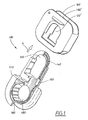
- Fig. 1 shows an example of an embodiment of a device 100 according to the present invention.
- the invention is primarily intended to be used for fastening emergency equipment such as for example life rafts, life buoys, radio transmitters, etc to a ship's deck or to a purpose-built structure on a ship's deck.
- the device 100 comprises a so-called shearing link 110, which in the example, is realised as a continuous link having a first 120 and a second opening 130, the workings of which will be seen in greater detail below, said two openings being separated from each other by a "cross-bar" in the device 100, thus giving the device a faint resemblance to the numera I"8".
- the first and second openings serve as a first respectively a second fastening facility for external fastening means, in a manner which will be explained in greater detail below.
- the design of the first and seconds fastening facilities in the device 100 as two separate openings in the device is not necessary the two fastening facilities can also, for example, be designed as one continuous opening ion the device 100.
- the shearing link 110 further comprises a means 140 for connecting the two openings or fastening facilities 120,130 in the device 100.
- this connecting means 140 is realised as a stainless steel wire, which is closed with a lock 150, in the example a so-called pressed talurite lock. Such a lock is for example described in WO 03/00642 .
- the connecting means 140 extends around the second 120 and third 130 fastening facility, i. e. the two openings in the shearing link, and will thus also extend around and connect any fastening means which are fastened to the fastening facilities 120, 130.
- connecting means can be given a well defined strength, for reasons which will be set out in greater detail below.
- shearing link can be made as an injection-moulded plastics part, having the connecting means or openings 120 130 moulded into the plastic, together with the cross-bar which separates them from each other.
- the shearing link can, of course, be realised in a large number of other ways, the important aspect is that the working which is described here is maintained.
- the device of the invention still depicted as a shearing link 110 further comprises a third fastening facility for external fastening means, said third fastening facility suitably being in the form of a groove 180, which runs around the whole or parts of the circumference of the device or shearing link 110, on its outside, and at least in part encloses or extends around the two openings 120, 130.
- the purpose of the third fastening means, i. e. the groove 180 will also be seen in greater detail below.
- the device according to the invention can also comprise a casing or a sleeve 160.
- This sleeve 160 comprises an opening 120'and, in a conceivable configuration, can be seen as two plates, which each have a through-hole in the middle and which are held together by two walls, each extending between opposite outer edges of the plates.
- the casing will then, in addition to the opening 120', also have a through-opening in the direction defined by the arrow A in Fig. 1 .
- the sleeve or casing 160 is designed to be slipped onto the device or in this embodiment shearing link so that the sleeve constitutes protection for at least that part of the shearing link which comprises the one opening 120, the sleeve being held in place on the device by means of snap-fastening, for example.
- Another advantage is that one and the same shearing link construction can be used for different applications, in which the sleeve can be the part which is modified according to the needs of the particular application, for example in terms of strength, colour, etc.
- the possibility of configuring the protection as a sleeve which can be given shape and colour as required means that the construction can be modified according to different requirements in different applications with different colour coding.
- the opening 120'of the sleeve When attached to the device 100, the opening 120'of the sleeve will, due to the design, at least in part coincide with the first fastening facility 120, this enabling that fastening facility to be used as intended.
- Fig. 2 shows a device 100 according to the invention in assembled state, in other words with the sleeve 160 slipped onto the main part of the invention, i. e. the shearing link 110.
- the opening 120'in the casing 160 coincides at least in part with one of the fastening facilities 120,130 in the shearing link, so that the assembled device 100 can be given a total of two such facilities, in which the one facility is defined by the opening in the casing 120' coinciding at least partly with one other opening 120 in the shearing link.
- the fastening facility in the device 100 which is defined by the opening 120'in the casing 160, because of the facility to give the casing a colour different from the shearing link, will be easily identifiable by a user, which means that the chance of mistaking the two fastening facilities during use of the device 100 is diminished, which, in turn, reduces the risk of the-device being wrongly coupled.
- the number of fastening facilities in the shearing link 110 and the sleeve 160 is only an example, it is understood that a device according to the invention can be configured with a largely arbitrary number of such facilities, which can be divided, in principle arbitrarily, between fastening facilities 120 in the shearing link which are enclosed by the sleeve and coincide with the openings 120'of the sleeve, and the fastening facilities 130 in the shearing link which are not enclosed by the sleeve.
- the sleeve 160 has "walls", which, when the sleeve is slipped onto the shearing link, will form a protective wall and guidance for fastening means 170, for example in the form of a rope, which are placed in the third fastening facility or groove 180, as will be seen in greater detail below.
- Fig. 3 shows the device 100 in operation.
- a first and a second external point, in the form of a shackle 145 and a so-called thimble 165, are mutually connected by means of the device 100 as follows : the shackle 145 is connected to the device 100 via the second fastening facility, the opening 130, and the thimble 165 is connected to the device 100 via a rope end 170 which passes into the groove 180, within the walls of the sleeve 160.
- the shackle can be used for connection to a ship's deck (not shown) or a structure in a ship's deck for fixing of emergency equipment, for example a life raft,and the thimble can used for connection to a line or a shackle which passes around the life raft and is connected to another point in the ship's deck.
- a life raft can thus be fixed to a ship's deck, for example, by means of the device and respectively a first 170 and a second 145 external fastening means which utilize the first and second fastening facilities (i. e. the openings in this embodiment) of the device, respectively.
- the rope end 170 connecting the thimble 165 to the device extends in the above-described groove 180 in the device, passes around the thimble 165 and additionally passes around at least a part of the shearing link which encloses the second fastening facility 130 in the device.
- the rope end can additionally run through a device 190 for releasing the life raft, in the illustrated example a hydrostat with a built-in knife which cuts off the rope end at a certain predefined pressure.
- the working of the device 190 is not of primary interest for the invention, and will thus not be described in further detail here.
- a third external fastening means 125 in the form of a further shackle, is additionally fixed.
- this shackle 125 in addition to its connection to the device 100, is fastened in a so-called"painter line", a release line, the working of which is familiar to the person skilled in the art and which will therefore not be described in greater detail here.
- This "painter line” is usually fastened with slack, so that it does not absorb any force when the device is operating, if the rope end 170 is under strain.
- the device comprises a connecting means, in an advantageous embodiment in the form of a wire 140, which extends around the two fastening facilities 120,130 so that the two shackles 125,145 will be mutually connected by this second connecting means 140. Since the strain in the fixing of the life raft via the device 100 will normally be absorbed by the rope end 170, the connecting means, the wire 140 will not be strained during operation.
- the life raft is fixed in the ship's deck by means of a device according to the invention, in the manner depicted in Fig. 3 . If the ship sinks, the hydrostat 190 will be activated at a certain predefined depth, whereupon the built-in knife cuts off the rope end 170. The connection between the ship's deck and the life raft breaks and the life raft begins to float to the surface. However, the life raft is still fixed in the"painter line", via the shackle 145 and the shackle 125, which are still fixed together by means of the wire 140.
- the "painter line" will also be stretched, whereupon the shackles 125,145 begin straining the wire 140, whereby the life raft is opened and inflated.
- the wire 140 will break once its tensile strength has been exceeded.
- the wire has a tensile strength which is less than that of the rope end 170, but this can, of course, be varied within the scope of the invention, depending on the particular application.
- Fig. 4 shows how a device according to the invention can be put together: the rope end 170 has been slipped around a part of the shearing link 110, in its groove 180. The rope end has further been slipped into the casing 160, within the aforementioned walls of the casing. Expediently,the rope end is knotted and is arranged next to an external device, such as the hydrostat, before the rope end is placed in the device 100, but can also be knotted subsequently.
- an external device such as the hydrostat
- the device can then be assembled in the manner previously described, namely by the casing 160 being put together with the shearing link 110 by the casing being slipped onto the shearing link and secured, for example, by snap-fastening.
- the invention is not limited to the embodiment described above, but can be freely modified within the scope of the following patent claims.
- One parameter which, for example, might be modified within the scope of the invention is the tensile strength of the wire in the shearing link, and hence the relationship between the strengths in the shearing link and the rope end employed in the use of the device.
Landscapes
- Engineering & Computer Science (AREA)
- Mechanical Engineering (AREA)
- Ocean & Marine Engineering (AREA)
- Emergency Lowering Means (AREA)
- Hooks, Suction Cups, And Attachment By Adhesive Means (AREA)
- Clamps And Clips (AREA)
- Catching Or Destruction (AREA)
- Connection Of Plates (AREA)
- Jib Cranes (AREA)
- Vibration Prevention Devices (AREA)
Abstract
Description
- The present invention relates to a device for fastening emergency equipment, such as, for example, a life raft, to a ship's deck or to a structure on a ship's deck. The invention results in an increased life span for such devices, and a more rational production than with previous devices.
- Various types of devices for fixing emergency equipment, for example life rafts, life buoys, radio transmitters, etc. to a ship's deck or a purpose-built structure on a ship's deck are previously known. The devices are often provided with some type of mechanism which releases the devices from the ship's deck if certain specific criteria are met which indicate the need to release the equipment, for example if the ship is about to sink or has met with some other kind of accident. Such arrangements are for example disclosed in
US 4,690,091 andEP 1 193 172 . These previously known appliances have a number of deficiencies, for example they are difficult and hence expensive to make, since their production requires a large number of working moments. - Another drawback with known appliances is that they often comprise a number of rope eyelets, shackles and similar fastening devices, which must be connected to different places on the deck or structure, which can lead to faulty connections due to handling errors and resulting malfunction.
- An object of the present invention is therefore to offer a device for fastening emergency equipment to a ship's deck or to a structure on a ship's deck, which device is simpler and hence cheaper to produce than known previous appliances. At the same time, an object of the present invention is to achieve a longer life than the life of previously known devices. Furthermore, the device according to the invention should not be prone to ageing phenomena to the same extent as previously known appliances, and should have a minimal scope for misconnection due to handling errors.
- The aforementioned objects are achieved according to the present invention by means of a device for fastening emergency equipment to a ship's deck or to a structure on a ship's deck, comprising a first and a second fastening facility for external fastening means, which device further comprises a third fastening facility for external fastening means. The first and second fastening facilities are constituted by at least one opening in the device, with the device further comprising a connecting means which extends around said first and second fastening facilities, thereby also extending around fastening means which utilise said first and second facilities. Examples of emergency equipment for use with the device according to the invention are life rafts, life buoys, radio transmitters,
- Suitably, but not necessarily, the third fastening facility is constituted by a groove in the device, which groove extends around at least part of said first and second fastening facilities.
- In addition, it is also suitable to let the first and the second fastening facilities be constituted by a first and a second opening respectively in the device, said openings being separate from one another in the device.
- In one particular embodiment, said connecting means are constituted by a loop of a material extending around the second and the third fastening facility.
- Also, said loop can preferably be integrated internally in the device.
- In addition, the device may further comprise a sleeve, said sleeve comprising an opening, with the sleeve being attached to the device in operation in such a manner that the opening in the sleeve at least in part coincides with the first fastening facility. The sleeve is suitably arranged to be attached to the device by means of snap-attaching.
- Because of this configuration, the device, in a manner to be explained in greater detail below, can be shaped to meet the demands placed upon it.
- For example, the device becomes simple to make as the third fastening facility is constituted by a groove in the device.
- The invention will be described in detail below with reference to the appended drawings, in which:
-
Fig. 1 shows the device according to the invention in dismantled state, with a part in sectional view, and -
Fig. 2 shows the device fromFig. 1 , in an assembled state, and -
Fig. 3 shows the device as it will appear in operation, andFigs. 4 and5 show a step in the assembly of a device according to the invention. -
Fig. 1 shows an example of an embodiment of adevice 100 according to the present invention. The invention is primarily intended to be used for fastening emergency equipment such as for example life rafts, life buoys, radio transmitters, etc to a ship's deck or to a purpose-built structure on a ship's deck. - In the illustrated embodiment, the
device 100 comprises a so-calledshearing link 110, which in the example, is realised as a continuous link having a first 120 and asecond opening 130, the workings of which will be seen in greater detail below, said two openings being separated from each other by a "cross-bar" in thedevice 100, thus giving the device a faint resemblance to the numera I"8". - The first and second openings serve as a first respectively a second fastening facility for external fastening means, in a manner which will be explained in greater detail below. As will be realized from the following explanation, the design of the first and seconds fastening facilities in the
device 100 as two separate openings in the device is not necessary the two fastening facilities can also, for example, be designed as one continuous opening ion thedevice 100. - The shearing
link 110 further comprises ameans 140 for connecting the two openings or fastening facilities 120,130 in thedevice 100. In the example, thisconnecting means 140 is realised as a stainless steel wire, which is closed with alock 150, in the example a so-called pressed talurite lock. Such a lock is for example described inWO 03/00642 connecting means 140 extends around the second 120 and third 130 fastening facility, i. e. the two openings in the shearing link, and will thus also extend around and connect any fastening means which are fastened to thefastening facilities - The important aspect of the invention is not, however, the exact implementation of the connecting means, but an important aspect is that the connecting means can be given a well defined strength, for reasons which will be set out in greater detail below.
- One example of how the shearing link can be made is for it to be realised as an injection-moulded plastics part, having the connecting means or
openings 120 130 moulded into the plastic, together with the cross-bar which separates them from each other. This is only one example, however; the shearing link can, of course, be realised in a large number of other ways, the important aspect is that the working which is described here is maintained. - The device of the invention, still depicted as a
shearing link 110 further comprises a third fastening facility for external fastening means, said third fastening facility suitably being in the form of agroove 180, which runs around the whole or parts of the circumference of the device or shearinglink 110, on its outside, and at least in part encloses or extends around the twoopenings groove 180, will also be seen in greater detail below. - The device according to the invention can also comprise a casing or a
sleeve 160. Thissleeve 160 comprises an opening 120'and, in a conceivable configuration, can be seen as two plates, which each have a through-hole in the middle and which are held together by two walls, each extending between opposite outer edges of the plates. The casing will then, in addition to the opening 120', also have a through-opening in the direction defined by the arrow A inFig. 1 . - The sleeve or
casing 160 is designed to be slipped onto the device or in this embodiment shearing link so that the sleeve constitutes protection for at least that part of the shearing link which comprises the one opening 120, the sleeve being held in place on the device by means of snap-fastening, for example. The fact that protection for part of the device is constituted by thesleeve 160, which is a separate part, offers a number of advantages, the sleeve can for example be replaced more easily than an integrated part, where necessary, if it is worn. Another advantage is that one and the same shearing link construction can be used for different applications, in which the sleeve can be the part which is modified according to the needs of the particular application, for example in terms of strength, colour, etc. The possibility of configuring the protection as a sleeve which can be given shape and colour as required means that the construction can be modified according to different requirements in different applications with different colour coding. - When attached to the
device 100, the opening 120'of the sleeve will, due to the design, at least in part coincide with thefirst fastening facility 120, this enabling that fastening facility to be used as intended. -
Fig. 2 shows adevice 100 according to the invention in assembled state, in other words with thesleeve 160 slipped onto the main part of the invention, i. e. theshearing link 110. As can be seen fromFig. 2 , the opening 120'in thecasing 160 coincides at least in part with one of the fastening facilities 120,130 in the shearing link, so that the assembleddevice 100 can be given a total of two such facilities, in which the one facility is defined by the opening in the casing 120' coinciding at least partly with one other opening 120 in the shearing link. - The fastening facility in the
device 100 which is defined by the opening 120'in thecasing 160, because of the facility to give the casing a colour different from the shearing link, will be easily identifiable by a user, which means that the chance of mistaking the two fastening facilities during use of thedevice 100 is diminished, which, in turn, reduces the risk of the-device being wrongly coupled. - Of course, the number of fastening facilities in the shearing
link 110 and thesleeve 160 is only an example, it is understood that a device according to the invention can be configured with a largely arbitrary number of such facilities, which can be divided, in principle arbitrarily, betweenfastening facilities 120 in the shearing link which are enclosed by the sleeve and coincide with the openings 120'of the sleeve, and thefastening facilities 130 in the shearing link which are not enclosed by the sleeve. - As stated above, the
sleeve 160 has "walls", which, when the sleeve is slipped onto the shearing link, will form a protective wall and guidance forfastening means 170, for example in the form of a rope, which are placed in the third fastening facility orgroove 180, as will be seen in greater detail below. -
Fig. 3 shows thedevice 100 in operation. A first and a second external point, in the form of ashackle 145 and a so-calledthimble 165, are mutually connected by means of thedevice 100 as follows : theshackle 145 is connected to thedevice 100 via the second fastening facility, theopening 130, and thethimble 165 is connected to thedevice 100 via arope end 170 which passes into thegroove 180, within the walls of thesleeve 160. - The shackle can be used for connection to a ship's deck (not shown) or a structure in a ship's deck for fixing of emergency equipment, for example a life raft,and the thimble can used for connection to a line or a shackle which passes around the life raft and is connected to another point in the ship's deck. A life raft can thus be fixed to a ship's deck, for example, by means of the device and respectively a first 170 and a second 145 external fastening means which utilize the first and second fastening facilities (i. e. the openings in this embodiment) of the device, respectively.
- The
rope end 170 connecting thethimble 165 to the device extends in the above-describedgroove 180 in the device, passes around thethimble 165 and additionally passes around at least a part of the shearing link which encloses thesecond fastening facility 130 in the device. The rope end can additionally run through adevice 190 for releasing the life raft, in the illustrated example a hydrostat with a built-in knife which cuts off the rope end at a certain predefined pressure. The working of thedevice 190 is not of primary interest for the invention, and will thus not be described in further detail here. - Via the
first fastening facility 120 in thedevice 100, a third external fastening means 125, in the form of a further shackle, is additionally fixed. Expediently, thisshackle 125, in addition to its connection to thedevice 100, is fastened in a so-called"painter line", a release line, the working of which is familiar to the person skilled in the art and which will therefore not be described in greater detail here. This"painter line"is usually fastened with slack, so that it does not absorb any force when the device is operating, if therope end 170 is under strain. - As described above in connection with
Fig. 1 , the device comprises a connecting means, in an advantageous embodiment in the form of awire 140, which extends around the two fastening facilities 120,130 so that the two shackles 125,145 will be mutually connected by this second connectingmeans 140. Since the strain in the fixing of the life raft via thedevice 100 will normally be absorbed by therope end 170, the connecting means, thewire 140 will not be strained during operation. - In order to facilitate understanding of the application for a
device 100 according to the invention, a possible process with a life raft will be described: - The life raft is fixed in the ship's deck by means of a device according to the invention, in the manner depicted in
Fig. 3 . If the ship sinks, thehydrostat 190 will be activated at a certain predefined depth, whereupon the built-in knife cuts off therope end 170. The connection between the ship's deck and the life raft breaks and the life raft begins to float to the surface. However, the life raft is still fixed in the"painter line", via theshackle 145 and theshackle 125, which are still fixed together by means of thewire 140. At a certain predefined depth, the "painter line"will also be stretched, whereupon the shackles 125,145 begin straining thewire 140, whereby the life raft is opened and inflated. Thewire 140 will break once its tensile strength has been exceeded. Expediently, the wire has a tensile strength which is less than that of therope end 170, but this can, of course, be varied within the scope of the invention, depending on the particular application. -
Fig. 4 shows how a device according to the invention can be put together: therope end 170 has been slipped around a part of theshearing link 110, in itsgroove 180. The rope end has further been slipped into thecasing 160, within the aforementioned walls of the casing. Expediently,the rope end is knotted and is arranged next to an external device, such as the hydrostat, before the rope end is placed in thedevice 100, but can also be knotted subsequently. - Once the rope end has been placed in this way around the
groove 180 in the device, the device can then be assembled in the manner previously described, namely by thecasing 160 being put together with theshearing link 110 by the casing being slipped onto the shearing link and secured, for example, by snap-fastening. - The invention is not limited to the embodiment described above, but can be freely modified within the scope of the following patent claims. One parameter which, for example, might be modified within the scope of the invention is the tensile strength of the wire in the shearing link, and hence the relationship between the strengths in the shearing link and the rope end employed in the use of the device.
Claims (7)
- Device (100) for fastening emergency equipment to a ship's deck or to a structure on a ship's deck, comprising a first (120) and a second (130) fastening facility for external fastening means (125,145), which device further comprises a third fastening facility for external fastening means (170),
characterized in that the first (120) and second (130) fastening facilities are constituted by at least one opening in the device (100), with the device further comprising a connecting means (140) which extends around said first (120) and second (130) fastening facilities, thereby also extending around fastening means (125,145) which utilise said first and second facilities. - The device (100) of claim 1, in which the third fastening facility is constituted by a groove (180) in the device (100), which groove extends around at least part of said first (120) and second (130) fastening facilities.
- The device (100) according to claim 1 or 2, in which the first (120) and the second (130) fastening facilities are constituted by a first and a second opening respectively in the device (100), said openings being separate from one another in the device.
- The device (100) according to any of claims 1-3, in which said connecting means (140) are constituted by a loop of a material extending around the second (120) and the third (110) fastening facility.
- The device (100) of claim 4, in which said loop is integrated internally in the device.
- The device (100) of any of claims 1-5, further comprising a sleeve (160), said sleeve comprising an opening (120'), with the sleeve being attached to the device in operation in such a manner that the opening in the sleeve at least in part coincides with the first fastening facility (120).
- The device of claim 6, with the sleeve (160) being arranged to be attached to the device (100) by means of snap-attaching.
Applications Claiming Priority (3)
| Application Number | Priority Date | Filing Date | Title |
|---|---|---|---|
| SE0201237 | 2002-04-23 | ||
| SE0201237A SE0201237D0 (en) | 2002-04-23 | 2002-04-23 | Device for attaching emergency equipment to a ship deck |
| PCT/SE2003/000642 WO2003106258A1 (en) | 2002-04-23 | 2003-04-22 | Device for fastening emergency equipment to a ship's deck |
Publications (2)
| Publication Number | Publication Date |
|---|---|
| EP1497171A1 EP1497171A1 (en) | 2005-01-19 |
| EP1497171B1 true EP1497171B1 (en) | 2010-05-19 |
Family
ID=20287669
Family Applications (1)
| Application Number | Title | Priority Date | Filing Date |
|---|---|---|---|
| EP03723554A Expired - Lifetime EP1497171B1 (en) | 2002-04-23 | 2003-04-22 | Device for fastening emergency equipment to a ship s deck |
Country Status (10)
| Country | Link |
|---|---|
| US (1) | US7302739B2 (en) |
| EP (1) | EP1497171B1 (en) |
| JP (1) | JP4242831B2 (en) |
| CN (1) | CN100515860C (en) |
| AT (1) | ATE468265T1 (en) |
| AU (1) | AU2003230484B2 (en) |
| DE (1) | DE60332612D1 (en) |
| DK (1) | DK1497171T3 (en) |
| SE (1) | SE0201237D0 (en) |
| WO (1) | WO2003106258A1 (en) |
Families Citing this family (9)
| Publication number | Priority date | Publication date | Assignee | Title |
|---|---|---|---|---|
| US8468927B2 (en) | 2008-04-16 | 2013-06-25 | QinetiQ North America, Inc. | Vehicle and structure shield with a cable frame |
| US7743597B2 (en) * | 2008-08-26 | 2010-06-29 | General Pneumatics Corp. | Marine safety device attachment with automatic release capability |
| US8375527B1 (en) | 2009-08-07 | 2013-02-19 | The Crosby Group, Inc. | Actuated wedge socket assembly |
| USD701452S1 (en) * | 2011-07-11 | 2014-03-25 | Nifco Inc. | Cord end cover |
| CN102602514A (en) * | 2012-04-16 | 2012-07-25 | 昆山博亚体育用品有限公司 | Canoe fast life-saving fastener |
| CN106516049B (en) * | 2016-12-20 | 2018-05-04 | 仲池 | A kind of adjustable lifebuoy fixing device |
| US11344085B2 (en) * | 2019-01-23 | 2022-05-31 | LT Brands, Inc. | Cord lock apparatus and belt with same |
| US11918087B2 (en) | 2019-09-18 | 2024-03-05 | LT Brands, Inc. | Cord lock apparatus and belt with same |
| JP7529491B2 (en) * | 2019-09-19 | 2024-08-06 | Ykk株式会社 | Cord stopper |
Family Cites Families (26)
| Publication number | Priority date | Publication date | Assignee | Title |
|---|---|---|---|---|
| US1090377A (en) * | 1911-05-15 | 1914-03-17 | Jasper Blackburn | Rope-clamp. |
| US1355004A (en) * | 1918-07-23 | 1920-10-05 | Sandford William Herbert | Device for securing hawsers, ropes, and the like |
| US1511917A (en) * | 1924-01-24 | 1924-10-14 | Arthur A Smith | Tire-chain fastener and lock |
| US1688461A (en) * | 1927-12-08 | 1928-10-23 | James T Hutton | Chain connecter |
| US2130040A (en) * | 1935-12-31 | 1938-09-13 | Macwhyte Company | Wire line sling and fitting therefor |
| US2222393A (en) * | 1939-07-06 | 1940-11-19 | Benjamin Joel Malvern | Antiskid chain |
| US3595097A (en) * | 1969-02-24 | 1971-07-27 | Kumakichi Araya | A chain including link plates having swaged portions |
| US3921792A (en) * | 1973-11-05 | 1975-11-25 | William S Anderson | Flexible link connecting structure for conveyor |
| FR2396897A1 (en) * | 1977-07-06 | 1979-02-02 | Sedis Transmissions Mec | TRANSMISSION CHANNEL |
| US4272952A (en) * | 1979-05-08 | 1981-06-16 | Dresser Industries, Inc. | Plastic chain and tubular link pin |
| CH642007A5 (en) * | 1979-07-26 | 1984-03-30 | Rud Ketten Rieger & Dietz | TIRE PROTECTION CHAIN. |
| US4368769A (en) * | 1980-12-04 | 1983-01-18 | Rookasin Jerome L | Tire chain |
| DE3129907C2 (en) * | 1981-07-24 | 1983-11-17 | Rud-Kettenfabrik Rieger & Dietz Gmbh U. Co, 7080 Aalen | Closure for tire chains |
| US4536921A (en) * | 1981-10-30 | 1985-08-27 | Geroh Gmbh, Mechanische Systeme | Cable clamp |
| JPS61211557A (en) * | 1985-03-13 | 1986-09-19 | Tsubakimoto Chain Co | Link plate for chain |
| SE454977B (en) * | 1985-03-18 | 1988-06-13 | Mats Hermansson | FIXING MACHINERY EQUIPPED TO BE EFFECTED BY PAPER |
| US5098349A (en) * | 1991-06-27 | 1992-03-24 | Wu Chia L | Chain |
| US5367798A (en) * | 1993-02-04 | 1994-11-29 | Indresco Inc. | Connector pin assembly for bucket rigging |
| US5507671A (en) * | 1994-09-15 | 1996-04-16 | Burndy Corporation | Wedge connector for electrical conductors |
| US5553360A (en) * | 1995-05-19 | 1996-09-10 | The Crosby Group, Inc. | Extended wedge socket assembly |
| US5988929A (en) * | 1996-10-09 | 1999-11-23 | Columbia Steel Casting Co. | Easy-out cable socket wedge and method for use thereof |
| US5913670A (en) * | 1996-12-19 | 1999-06-22 | Anderson; Erik S. | Breakaway links for underwater gear |
| DE19707966A1 (en) * | 1997-02-27 | 1998-09-10 | Kabelschlepp Gmbh | Energy guiding chain with chain links that have a core of high strength and a method for producing such a chain link |
| EP1193172A3 (en) | 2000-09-28 | 2003-01-02 | Thanner Development A/S | A release mechanism for releasing nautical life-saving equipment |
| ITMI20011308A1 (en) | 2001-06-21 | 2002-12-21 | Nicox Sa | DRUGS FOR CHRONIC PAIN |
| US6898827B1 (en) * | 2003-08-06 | 2005-05-31 | The Crosby Group, Inc. | Wedge socket with actuator assembly |
-
2002
- 2002-04-23 SE SE0201237A patent/SE0201237D0/en unknown
-
2003
- 2003-04-22 WO PCT/SE2003/000642 patent/WO2003106258A1/en not_active Ceased
- 2003-04-22 CN CNB038088045A patent/CN100515860C/en not_active Expired - Fee Related
- 2003-04-22 US US10/508,078 patent/US7302739B2/en not_active Expired - Lifetime
- 2003-04-22 DE DE60332612T patent/DE60332612D1/en not_active Expired - Lifetime
- 2003-04-22 DK DK03723554.6T patent/DK1497171T3/en active
- 2003-04-22 JP JP2004513108A patent/JP4242831B2/en not_active Expired - Fee Related
- 2003-04-22 AU AU2003230484A patent/AU2003230484B2/en not_active Ceased
- 2003-04-22 EP EP03723554A patent/EP1497171B1/en not_active Expired - Lifetime
- 2003-04-22 AT AT03723554T patent/ATE468265T1/en not_active IP Right Cessation
Also Published As
| Publication number | Publication date |
|---|---|
| EP1497171A1 (en) | 2005-01-19 |
| AU2003230484B2 (en) | 2009-05-21 |
| JP4242831B2 (en) | 2009-03-25 |
| SE0201237D0 (en) | 2002-04-23 |
| US20050155194A1 (en) | 2005-07-21 |
| DK1497171T3 (en) | 2010-08-30 |
| CN100515860C (en) | 2009-07-22 |
| AU2003230484A1 (en) | 2003-12-31 |
| WO2003106258A1 (en) | 2003-12-24 |
| DE60332612D1 (en) | 2010-07-01 |
| JP2006500264A (en) | 2006-01-05 |
| ATE468265T1 (en) | 2010-06-15 |
| CN1646363A (en) | 2005-07-27 |
| US7302739B2 (en) | 2007-12-04 |
Similar Documents
| Publication | Publication Date | Title |
|---|---|---|
| US7302739B2 (en) | Device for fastening emergency equipment to a ship's deck | |
| US7743597B2 (en) | Marine safety device attachment with automatic release capability | |
| CN104740848B (en) | improved pulley device | |
| US6712181B2 (en) | Safety rope grab device | |
| KR960033339A (en) | Band installation structure | |
| MX166910B (en) | CABLE CLOSURE AND TRANSMISSION MEDIA SYSTEM | |
| CN109310895A (en) | Weight-bearing fall protection connector with wireless fall indicator | |
| US11911639B2 (en) | Portable tool for mobile use | |
| KR102469332B1 (en) | Spraying assembly and agricultural plant protection unmanned aerial vehicle | |
| US6564500B1 (en) | Breakable link | |
| CN102834646A (en) | A mechanical fuse, a neck cord comprising a mechanical fuse and a method of connecting a mechanical fuse to a neck cord | |
| WO2019175543A1 (en) | Energy absorber device | |
| DE50107289D1 (en) | burst protection | |
| CN216908956U (en) | Electrician special safety belt with safety self-checking function | |
| US20200385942A1 (en) | Traffic monitoring arrangement | |
| GB2486012A (en) | Alarm for fall arrest system | |
| CN220535899U (en) | Connecting device for releasing ship life raft | |
| WO2026033453A1 (en) | System for detecting fall event | |
| CN221408941U (en) | Anti-disassembly monitoring wearable device housing and wearable device | |
| CN113952644A (en) | Double-control safety belt with auxiliary alarm function | |
| CN218790922U (en) | Chain structure | |
| KR200381854Y1 (en) | a belt for the ocean activities with safety tube | |
| JPH04507035A (en) | Device for creating and sealing electrical contact between two arm band antenna parts of a selective call receiver | |
| KR20240129955A (en) | Apparatus for notifying worker drop | |
| SU451566A1 (en) | Signal device overloads paired cargo ropes |
Legal Events
| Date | Code | Title | Description |
|---|---|---|---|
| PUAI | Public reference made under article 153(3) epc to a published international application that has entered the european phase |
Free format text: ORIGINAL CODE: 0009012 |
|
| 17P | Request for examination filed |
Effective date: 20041018 |
|
| AK | Designated contracting states |
Kind code of ref document: A1 Designated state(s): AT BE BG CH CY CZ DE DK EE ES FI FR GB GR HU IE IT LI LU MC NL PT RO SE SI SK TR |
|
| AX | Request for extension of the european patent |
Extension state: AL LT LV MK |
|
| 17Q | First examination report despatched |
Effective date: 20081212 |
|
| GRAP | Despatch of communication of intention to grant a patent |
Free format text: ORIGINAL CODE: EPIDOSNIGR1 |
|
| GRAS | Grant fee paid |
Free format text: ORIGINAL CODE: EPIDOSNIGR3 |
|
| GRAA | (expected) grant |
Free format text: ORIGINAL CODE: 0009210 |
|
| AK | Designated contracting states |
Kind code of ref document: B1 Designated state(s): AT BE BG CH CY CZ DE DK EE ES FI FR GB GR HU IE IT LI LU MC NL PT RO SE SI SK TR |
|
| REG | Reference to a national code |
Ref country code: GB Ref legal event code: FG4D |
|
| REG | Reference to a national code |
Ref country code: CH Ref legal event code: EP |
|
| REG | Reference to a national code |
Ref country code: IE Ref legal event code: FG4D |
|
| REF | Corresponds to: |
Ref document number: 60332612 Country of ref document: DE Date of ref document: 20100701 Kind code of ref document: P |
|
| REG | Reference to a national code |
Ref country code: SE Ref legal event code: TRGR |
|
| REG | Reference to a national code |
Ref country code: DK Ref legal event code: T3 |
|
| REG | Reference to a national code |
Ref country code: NL Ref legal event code: VDEP Effective date: 20100519 |
|
| REG | Reference to a national code |
Ref country code: GR Ref legal event code: EP Ref document number: 20100401952 Country of ref document: GR |
|
| PG25 | Lapsed in a contracting state [announced via postgrant information from national office to epo] |
Ref country code: ES Free format text: LAPSE BECAUSE OF FAILURE TO SUBMIT A TRANSLATION OF THE DESCRIPTION OR TO PAY THE FEE WITHIN THE PRESCRIBED TIME-LIMIT Effective date: 20100830 |
|
| PG25 | Lapsed in a contracting state [announced via postgrant information from national office to epo] |
Ref country code: FI Free format text: LAPSE BECAUSE OF FAILURE TO SUBMIT A TRANSLATION OF THE DESCRIPTION OR TO PAY THE FEE WITHIN THE PRESCRIBED TIME-LIMIT Effective date: 20100519 Ref country code: AT Free format text: LAPSE BECAUSE OF FAILURE TO SUBMIT A TRANSLATION OF THE DESCRIPTION OR TO PAY THE FEE WITHIN THE PRESCRIBED TIME-LIMIT Effective date: 20100519 Ref country code: SI Free format text: LAPSE BECAUSE OF FAILURE TO SUBMIT A TRANSLATION OF THE DESCRIPTION OR TO PAY THE FEE WITHIN THE PRESCRIBED TIME-LIMIT Effective date: 20100519 |
|
| PG25 | Lapsed in a contracting state [announced via postgrant information from national office to epo] |
Ref country code: CY Free format text: LAPSE BECAUSE OF FAILURE TO SUBMIT A TRANSLATION OF THE DESCRIPTION OR TO PAY THE FEE WITHIN THE PRESCRIBED TIME-LIMIT Effective date: 20100519 |
|
| PG25 | Lapsed in a contracting state [announced via postgrant information from national office to epo] |
Ref country code: NL Free format text: LAPSE BECAUSE OF FAILURE TO SUBMIT A TRANSLATION OF THE DESCRIPTION OR TO PAY THE FEE WITHIN THE PRESCRIBED TIME-LIMIT Effective date: 20100519 Ref country code: EE Free format text: LAPSE BECAUSE OF FAILURE TO SUBMIT A TRANSLATION OF THE DESCRIPTION OR TO PAY THE FEE WITHIN THE PRESCRIBED TIME-LIMIT Effective date: 20100519 Ref country code: PT Free format text: LAPSE BECAUSE OF FAILURE TO SUBMIT A TRANSLATION OF THE DESCRIPTION OR TO PAY THE FEE WITHIN THE PRESCRIBED TIME-LIMIT Effective date: 20100920 |
|
| PG25 | Lapsed in a contracting state [announced via postgrant information from national office to epo] |
Ref country code: SK Free format text: LAPSE BECAUSE OF FAILURE TO SUBMIT A TRANSLATION OF THE DESCRIPTION OR TO PAY THE FEE WITHIN THE PRESCRIBED TIME-LIMIT Effective date: 20100519 Ref country code: CZ Free format text: LAPSE BECAUSE OF FAILURE TO SUBMIT A TRANSLATION OF THE DESCRIPTION OR TO PAY THE FEE WITHIN THE PRESCRIBED TIME-LIMIT Effective date: 20100519 Ref country code: BE Free format text: LAPSE BECAUSE OF FAILURE TO SUBMIT A TRANSLATION OF THE DESCRIPTION OR TO PAY THE FEE WITHIN THE PRESCRIBED TIME-LIMIT Effective date: 20100519 Ref country code: RO Free format text: LAPSE BECAUSE OF FAILURE TO SUBMIT A TRANSLATION OF THE DESCRIPTION OR TO PAY THE FEE WITHIN THE PRESCRIBED TIME-LIMIT Effective date: 20100519 |
|
| PLBE | No opposition filed within time limit |
Free format text: ORIGINAL CODE: 0009261 |
|
| STAA | Information on the status of an ep patent application or granted ep patent |
Free format text: STATUS: NO OPPOSITION FILED WITHIN TIME LIMIT |
|
| PG25 | Lapsed in a contracting state [announced via postgrant information from national office to epo] |
Ref country code: IT Free format text: LAPSE BECAUSE OF FAILURE TO SUBMIT A TRANSLATION OF THE DESCRIPTION OR TO PAY THE FEE WITHIN THE PRESCRIBED TIME-LIMIT Effective date: 20100519 |
|
| 26N | No opposition filed |
Effective date: 20110222 |
|
| REG | Reference to a national code |
Ref country code: DE Ref legal event code: R097 Ref document number: 60332612 Country of ref document: DE Effective date: 20110221 |
|
| PG25 | Lapsed in a contracting state [announced via postgrant information from national office to epo] |
Ref country code: MC Free format text: LAPSE BECAUSE OF NON-PAYMENT OF DUE FEES Effective date: 20110430 |
|
| REG | Reference to a national code |
Ref country code: CH Ref legal event code: PL |
|
| PG25 | Lapsed in a contracting state [announced via postgrant information from national office to epo] |
Ref country code: CH Free format text: LAPSE BECAUSE OF NON-PAYMENT OF DUE FEES Effective date: 20110430 Ref country code: LI Free format text: LAPSE BECAUSE OF NON-PAYMENT OF DUE FEES Effective date: 20110430 |
|
| PG25 | Lapsed in a contracting state [announced via postgrant information from national office to epo] |
Ref country code: LU Free format text: LAPSE BECAUSE OF NON-PAYMENT OF DUE FEES Effective date: 20110422 |
|
| PG25 | Lapsed in a contracting state [announced via postgrant information from national office to epo] |
Ref country code: BG Free format text: LAPSE BECAUSE OF FAILURE TO SUBMIT A TRANSLATION OF THE DESCRIPTION OR TO PAY THE FEE WITHIN THE PRESCRIBED TIME-LIMIT Effective date: 20100819 |
|
| PG25 | Lapsed in a contracting state [announced via postgrant information from national office to epo] |
Ref country code: HU Free format text: LAPSE BECAUSE OF FAILURE TO SUBMIT A TRANSLATION OF THE DESCRIPTION OR TO PAY THE FEE WITHIN THE PRESCRIBED TIME-LIMIT Effective date: 20100519 |
|
| REG | Reference to a national code |
Ref country code: DE Ref legal event code: R082 Ref document number: 60332612 Country of ref document: DE Representative=s name: HOFFMANN - EITLE, DE |
|
| REG | Reference to a national code |
Ref country code: DE Ref legal event code: R082 Ref document number: 60332612 Country of ref document: DE Representative=s name: HOFFMANN - EITLE, DE Effective date: 20140812 Ref country code: DE Ref legal event code: R081 Ref document number: 60332612 Country of ref document: DE Owner name: ERNSTROEM TECHNOLOGY AB, SE Free format text: FORMER OWNER: C M HAMMAR UTVECKLING AB, VAESTRA FROELUNDA, SE Effective date: 20140812 Ref country code: DE Ref legal event code: R082 Ref document number: 60332612 Country of ref document: DE Representative=s name: HOFFMANN - EITLE PATENT- UND RECHTSANWAELTE PA, DE Effective date: 20140812 |
|
| REG | Reference to a national code |
Ref country code: GB Ref legal event code: 732E Free format text: REGISTERED BETWEEN 20150129 AND 20150204 |
|
| REG | Reference to a national code |
Ref country code: FR Ref legal event code: TP Owner name: ERNSTROM TECHNOLOGY AB, SE Effective date: 20150130 |
|
| REG | Reference to a national code |
Ref country code: FR Ref legal event code: PLFP Year of fee payment: 14 |
|
| REG | Reference to a national code |
Ref country code: FR Ref legal event code: PLFP Year of fee payment: 15 |
|
| REG | Reference to a national code |
Ref country code: FR Ref legal event code: PLFP Year of fee payment: 16 |
|
| PGFP | Annual fee paid to national office [announced via postgrant information from national office to epo] |
Ref country code: IE Payment date: 20180411 Year of fee payment: 16 Ref country code: DE Payment date: 20180418 Year of fee payment: 16 |
|
| PGFP | Annual fee paid to national office [announced via postgrant information from national office to epo] |
Ref country code: DK Payment date: 20190416 Year of fee payment: 17 |
|
| PGFP | Annual fee paid to national office [announced via postgrant information from national office to epo] |
Ref country code: PT Payment date: 20190206 Year of fee payment: 15 Ref country code: FR Payment date: 20190416 Year of fee payment: 17 Ref country code: SE Payment date: 20190416 Year of fee payment: 17 |
|
| REG | Reference to a national code |
Ref country code: DE Ref legal event code: R119 Ref document number: 60332612 Country of ref document: DE |
|
| PG25 | Lapsed in a contracting state [announced via postgrant information from national office to epo] |
Ref country code: DE Free format text: LAPSE BECAUSE OF NON-PAYMENT OF DUE FEES Effective date: 20191101 |
|
| PG25 | Lapsed in a contracting state [announced via postgrant information from national office to epo] |
Ref country code: IE Free format text: LAPSE BECAUSE OF NON-PAYMENT OF DUE FEES Effective date: 20190422 |
|
| PGFP | Annual fee paid to national office [announced via postgrant information from national office to epo] |
Ref country code: TR Payment date: 20200408 Year of fee payment: 18 |
|
| PGFP | Annual fee paid to national office [announced via postgrant information from national office to epo] |
Ref country code: GB Payment date: 20200417 Year of fee payment: 18 |
|
| REG | Reference to a national code |
Ref country code: DK Ref legal event code: EBP Effective date: 20200430 |
|
| PG25 | Lapsed in a contracting state [announced via postgrant information from national office to epo] |
Ref country code: SE Free format text: LAPSE BECAUSE OF NON-PAYMENT OF DUE FEES Effective date: 20200423 Ref country code: GR Free format text: LAPSE BECAUSE OF NON-PAYMENT OF DUE FEES Effective date: 20201109 Ref country code: FR Free format text: LAPSE BECAUSE OF NON-PAYMENT OF DUE FEES Effective date: 20200430 |
|
| PG25 | Lapsed in a contracting state [announced via postgrant information from national office to epo] |
Ref country code: DK Free format text: LAPSE BECAUSE OF NON-PAYMENT OF DUE FEES Effective date: 20200430 |
|
| GBPC | Gb: european patent ceased through non-payment of renewal fee |
Effective date: 20210422 |
|
| PG25 | Lapsed in a contracting state [announced via postgrant information from national office to epo] |
Ref country code: GB Free format text: LAPSE BECAUSE OF NON-PAYMENT OF DUE FEES Effective date: 20210422 |
|
| PG25 | Lapsed in a contracting state [announced via postgrant information from national office to epo] |
Ref country code: TR Free format text: LAPSE BECAUSE OF NON-PAYMENT OF DUE FEES Effective date: 20210422 |