EP1496633A1 - Multi-carrier communication device and multi-carrier communication method - Google Patents
Multi-carrier communication device and multi-carrier communication method Download PDFInfo
- Publication number
- EP1496633A1 EP1496633A1 EP03719093A EP03719093A EP1496633A1 EP 1496633 A1 EP1496633 A1 EP 1496633A1 EP 03719093 A EP03719093 A EP 03719093A EP 03719093 A EP03719093 A EP 03719093A EP 1496633 A1 EP1496633 A1 EP 1496633A1
- Authority
- EP
- European Patent Office
- Prior art keywords
- section
- retransmission
- bits
- data
- multicarrier
- Prior art date
- Legal status (The legal status is an assumption and is not a legal conclusion. Google has not performed a legal analysis and makes no representation as to the accuracy of the status listed.)
- Withdrawn
Links
Images









Classifications
-
- H—ELECTRICITY
- H04—ELECTRIC COMMUNICATION TECHNIQUE
- H04L—TRANSMISSION OF DIGITAL INFORMATION, e.g. TELEGRAPHIC COMMUNICATION
- H04L5/00—Arrangements affording multiple use of the transmission path
- H04L5/02—Channels characterised by the type of signal
- H04L5/023—Multiplexing of multicarrier modulation signals, e.g. multi-user orthogonal frequency division multiple access [OFDMA]
- H04L5/026—Multiplexing of multicarrier modulation signals, e.g. multi-user orthogonal frequency division multiple access [OFDMA] using code division
-
- H—ELECTRICITY
- H03—ELECTRONIC CIRCUITRY
- H03M—CODING; DECODING; CODE CONVERSION IN GENERAL
- H03M13/00—Coding, decoding or code conversion, for error detection or error correction; Coding theory basic assumptions; Coding bounds; Error probability evaluation methods; Channel models; Simulation or testing of codes
- H03M13/27—Coding, decoding or code conversion, for error detection or error correction; Coding theory basic assumptions; Coding bounds; Error probability evaluation methods; Channel models; Simulation or testing of codes using interleaving techniques
-
- H—ELECTRICITY
- H04—ELECTRIC COMMUNICATION TECHNIQUE
- H04L—TRANSMISSION OF DIGITAL INFORMATION, e.g. TELEGRAPHIC COMMUNICATION
- H04L1/00—Arrangements for detecting or preventing errors in the information received
- H04L1/0001—Systems modifying transmission characteristics according to link quality, e.g. power backoff
- H04L1/0002—Systems modifying transmission characteristics according to link quality, e.g. power backoff by adapting the transmission rate
- H04L1/0003—Systems modifying transmission characteristics according to link quality, e.g. power backoff by adapting the transmission rate by switching between different modulation schemes
-
- H—ELECTRICITY
- H04—ELECTRIC COMMUNICATION TECHNIQUE
- H04L—TRANSMISSION OF DIGITAL INFORMATION, e.g. TELEGRAPHIC COMMUNICATION
- H04L1/00—Arrangements for detecting or preventing errors in the information received
- H04L1/004—Arrangements for detecting or preventing errors in the information received by using forward error control
- H04L1/0041—Arrangements at the transmitter end
- H04L1/0043—Realisations of complexity reduction techniques, e.g. use of look-up tables
-
- H—ELECTRICITY
- H04—ELECTRIC COMMUNICATION TECHNIQUE
- H04L—TRANSMISSION OF DIGITAL INFORMATION, e.g. TELEGRAPHIC COMMUNICATION
- H04L1/00—Arrangements for detecting or preventing errors in the information received
- H04L1/004—Arrangements for detecting or preventing errors in the information received by using forward error control
- H04L1/0056—Systems characterized by the type of code used
- H04L1/0071—Use of interleaving
-
- H—ELECTRICITY
- H04—ELECTRIC COMMUNICATION TECHNIQUE
- H04L—TRANSMISSION OF DIGITAL INFORMATION, e.g. TELEGRAPHIC COMMUNICATION
- H04L1/00—Arrangements for detecting or preventing errors in the information received
- H04L1/02—Arrangements for detecting or preventing errors in the information received by diversity reception
- H04L1/06—Arrangements for detecting or preventing errors in the information received by diversity reception using space diversity
- H04L1/0618—Space-time coding
-
- H—ELECTRICITY
- H04—ELECTRIC COMMUNICATION TECHNIQUE
- H04L—TRANSMISSION OF DIGITAL INFORMATION, e.g. TELEGRAPHIC COMMUNICATION
- H04L1/00—Arrangements for detecting or preventing errors in the information received
- H04L1/12—Arrangements for detecting or preventing errors in the information received by using return channel
- H04L1/16—Arrangements for detecting or preventing errors in the information received by using return channel in which the return channel carries supervisory signals, e.g. repetition request signals
- H04L1/18—Automatic repetition systems, e.g. Van Duuren systems
- H04L1/1867—Arrangements specially adapted for the transmitter end
- H04L1/1874—Buffer management
-
- H—ELECTRICITY
- H04—ELECTRIC COMMUNICATION TECHNIQUE
- H04L—TRANSMISSION OF DIGITAL INFORMATION, e.g. TELEGRAPHIC COMMUNICATION
- H04L1/00—Arrangements for detecting or preventing errors in the information received
- H04L1/12—Arrangements for detecting or preventing errors in the information received by using return channel
- H04L1/16—Arrangements for detecting or preventing errors in the information received by using return channel in which the return channel carries supervisory signals, e.g. repetition request signals
- H04L1/18—Automatic repetition systems, e.g. Van Duuren systems
- H04L1/1867—Arrangements specially adapted for the transmitter end
- H04L1/1893—Physical mapping arrangements
-
- H—ELECTRICITY
- H04—ELECTRIC COMMUNICATION TECHNIQUE
- H04L—TRANSMISSION OF DIGITAL INFORMATION, e.g. TELEGRAPHIC COMMUNICATION
- H04L27/00—Modulated-carrier systems
- H04L27/26—Systems using multi-frequency codes
- H04L27/2601—Multicarrier modulation systems
- H04L27/2626—Arrangements specific to the transmitter only
-
- H—ELECTRICITY
- H04—ELECTRIC COMMUNICATION TECHNIQUE
- H04L—TRANSMISSION OF DIGITAL INFORMATION, e.g. TELEGRAPHIC COMMUNICATION
- H04L27/00—Modulated-carrier systems
- H04L27/26—Systems using multi-frequency codes
- H04L27/2601—Multicarrier modulation systems
- H04L27/2647—Arrangements specific to the receiver only
-
- H—ELECTRICITY
- H04—ELECTRIC COMMUNICATION TECHNIQUE
- H04L—TRANSMISSION OF DIGITAL INFORMATION, e.g. TELEGRAPHIC COMMUNICATION
- H04L1/00—Arrangements for detecting or preventing errors in the information received
- H04L1/12—Arrangements for detecting or preventing errors in the information received by using return channel
- H04L1/16—Arrangements for detecting or preventing errors in the information received by using return channel in which the return channel carries supervisory signals, e.g. repetition request signals
- H04L1/18—Automatic repetition systems, e.g. Van Duuren systems
- H04L1/1829—Arrangements specially adapted for the receiver end
- H04L1/1835—Buffer management
- H04L1/1845—Combining techniques, e.g. code combining
Definitions
- the present invention relates to a multicarrier communication apparatus and multicarrier communication method that adopts a retransmission technique to improve an error rate.
- a reception level differs for each subcarrier because of frequency-selective fading. Accordingly, the reception level of a signal on which a subcarrier with a certain frequency is superimposed becomes high but the reception level of the signal on which another subcarrier is superimposed becomes low. As a result, the error rate of the signal on which a subcarrier with a low reception level does not easily achieve a desired value, so that the number of retransmissions increases.
- An object of the present invention is to more increase improvement effect of an error rate characteristic by retransmission to improve a throughput characteristic in multicarrier communications.
- This object can be attained by interchanging high-order bits where an error easily occurs and low-order bits where an error does not easily occur for each retransmission to provide M-ary modulation when M-ary modulation is provided to transmission data to perform multicarrier transmission to a modulated symbol. Moreover, bit interleave processing is performed such that bits forming M-ary modulated one symbol differ for each retransmission, thereby making it possible to further improve the throughput characteristic.
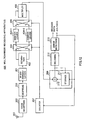
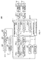
- 100 indicates a configuration of a multicarrier transmitting apparatus as a whole according to Embodiment 1 of the present invention.
- the multicarrier transmitting apparatus 100 is used as a transmission system of a multicarrier communication apparatus according to the present invention.
- the multicarrier transmitting apparatus 100 is provided in a radio base station apparatus and a communication terminal apparatus.
- the multicarrier transmitting apparatus 100 performs M-ary modulation processing to transmission data, performs spread processing to a symbol obtained by modulation, superimposes a chip obtained by spreading on a plurality of subcarriers orthogonal to each other, and transmits it. Namely, the multicarrier transmitting apparatus 100 in this Embodiment sends transmission data by OFDM (Orthogonal Frequency Division Multiplexing) - CDMA (Code Division Multiple Access).
- OFDM Orthogonal Frequency Division Multiplexing
- CDMA Code Division Multiple Access
- the multicarrier transmitting apparatus 100 codes transmission data using a coding section 101 and sends the coded data to a storage section 102.
- the storage section 102 is read and controlled based on a count value of a counter 103.
- the counter 103 increments the count value every time when a NACK signal (repeat request signal) is sent from a receiving side, and resets the count value to 0 when an ACK signal is sent.
- the storage section 102 sends data stored every time when the count value is incremented to the sequence converting section 104 (namely, retransmission data is transmitted).
- the count value becomes 0 data from the coding section 101 is directly transmitted to the sequence converting section 104 (namely, initial transmission data is transmitted).
- the sequence converting section 104 interchanges the order of high-order bits where an error does not easily occur and low-order bits where an error easily occurs, both which are modulated by a next M-ary modulating section 105, every time when the count value from the counter 103 is incremented.
- the M-ary modulating section 105 modulates a plurality of bits of data input from the sequence converting section 104 to one symbol.
- the M-ary modulating section 105 performs 16QAM (Quadrature Amplitude Modulation) to the input data to modulate four bits to one symbol.
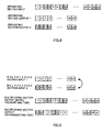
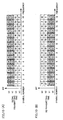
- FIG.2(A) is a view illustrating an array of bits input to the sequence converting section 104.
- FIG.2(B) is a view illustrating an array of bits forming each symbol at an initial transmitting time.
- FIG.2(C) is a view illustrating an array of bits forming each symbol at a retransmitting time (first retransmitting time).
- FIG.2(D) is a view illustrating an array of bits output from the sequence converting section 104 at a retransmitting time (first retransmitting time).
- b0 and b1 show high-order bits where an error does not easily occur when being 16QAM modulated and b2 and b3 show low-order bits where an error easily occurs.
- the high-order bits and low-order bits are interchanged by the sequence converting section 104 at the initial transmitting time and the retransmitting time. Referring to, for example, symbol No.
- bits 1 and 2 are placed as high-order bits and bits 3 and 4 are placed as low-order bits at the initial transmitting time (FIG.2(B)), while bits 3 and 4 are placed as high-order bits and bits 1 and 2 are placed as low-order bits at the retransmitting time (FIG.2(C)).
- the M-ary modulated symbol is input to a selection circuit 106.
- a plurality of interleavers 107-1, 107-2, ... 107-N, each having a different interleave pattern, is connected to an output side of the selection circuit 106.
- the selection circuit 106 selects interleavers 107-1, 107-2, ... 107-N to have the modulated symbol inputted according to the count value from the counter 103. Accordingly, symbols, each having a different array order for each retransmission, are sent to a spreading section 108.
- the spreading section 108 multiplies the input symbol by a spreading code and thereby spreads the symbol to a chip unit.
- An OFDM transmitting section 109 includes an IFFT (Inverse Fast Fourier Transform circuit) and a radio transmitting circuit, and superimposes a plurality of subcarriers orthogonal to each other on a chip obtained by spreading. A signal subjected to OFDM transmission processing is transmitted through an antenna 110.
- IFFT Inverse Fast Fourier Transform circuit
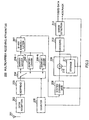
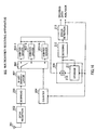
- FIG.3 shows a configuration of a multicarrier receiving apparatus 200 that receives a multicarrier signal transmitted from the multicarrier transmitting apparatus 100.
- the multicarrier receiving apparatus 200 is used as a receiving system of the multicarrier communication apparatus of the present invention.
- the multicarrier receiving apparatus 200 inputs a received signal to an OFDM receiving section 202 through an antenna 201.
- the OFDM receiving section 202 includes a radio receiving section and an FFT (Fast Fourier transform circuit), and extracts each chip superimposed on the plurality of subcarriers.
- a despreading section 203 despreads an input signal using a spreading code, so that an unspread symbol is restored and the restored symbol is transmitted to a selection circuit 204.
- a plurality of deinterleavers 206-1, 206-2, ... 206-N, each having a different deinterleave pattern, is connected to an output side of the selection circuit 204.
- Each of deinterleavers 206-1, 206-2, ... 206-N returns each symbol to the original array by performing reverse processing of the interleavers 107-1, 107-2, ... 107-N (FIG.1) on the transmitting side.
- the selection circuit 204 selects the deinterleavers 206-1, 206-2, ... 206-N to have an input signal outputted according to a count value from a counter 205.
- the counter 205 is incremented every time when a NACK signal is input similar to the counter 103 on the transmitting side (FIG.1).
- the interleavers 107-1, 107-2, ... 107-N (FIG.1) and the deinterleavers 206-1, 206-2, ... 206-N are selected according to the number of retransmissions, so that the array of symbol is returned to the original by the deinterleavers 206-1, 206-2, ... 206-N.
- the symbol returned to the original array by the deinterleavers 206-1, 206-2, ... 206-N is input to an M-ary demodulating section 207.
- the M-ary demodulating section 207 performs demodulation processing corresponding to the M-ary modulating section 105 (FIG.1) to demodulate four-bit data from one symbol.
- a sequence converting section 208 performs sequence conversion that is reverse to the sequence converting section 104 (FIG.1) on the transmitting side according to the number of retransmissions. More specifically, the input bits are directly output with the array unchanged at the time of receiving the initially transmitted data, while the arrays of the high-order bits and low-order bits are interchanged for each retransmission when the retransmitted signal is received. Consequently, the signal with the same bit array as the transmitted data can be obtained.
- An output of the sequence converting section 208 is input to a combining circuit 209 that combines retransmitted packets.
- the combining circuit 209 includes a storage section 211 and an adding section 210, and packet data stored in the storage section 211 up to the current retransmission and currently retransmitted packet data are added by an adding section 210. For example, when currently input packet data is packet data at a second retransmission, combined packet data, including data stored in the storage section 211 at the initial transmission and data at the first retransmission, is combined with currently retransmitted packet data.
- Combined packet data is decoded by a decoding section 212 and an error detecting section 213 perform error detection such as CRC (Cyclic Redundancy Check). Accordingly, decoded data is output from the error detecting section 213 and an ACK signal is output when CRC is OK and a NACK signal is output when CRC is NG. ACK/NACK signals are sent to the counter 205 and also to the multicarrier transmitting apparatus 100 (FIG.1).
- CRC Cyclic Redundancy Check
- FIG.4 shows a mapping position on an I-Q plane of each symbol by 16QAM.
- a decision threshold value with a width il in the figure is used as an in-phase component and a decision threshold value with a width q1 in the figure as a quadrature component, and soft decision processing is performed.
- a decision threshold value with a width i2 is used as an in-phase component and a decision threshold value with a width q2 is used as a quadrature component, and soft decision processing is performed.
- widths i2 and q2 of the decision threshold values of the low-order two bits are narrower than widths i1 and q1 of the decision threshold values of the high-order two bits, an error easily occurs as compared with the high-order two bits when symbol phase and amplitude are varied by a propagation path.
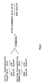
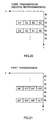
- FIG.5 shows a relationship between SIR (Signal to Interference Ratio) and BER (Bit Error Rate) in connection with the high-order two bits S0, S1 and the low-order two bits S2, S3.
- SIR Signal to Interference Ratio
- BER Bit Error Rate
- bits S0 and S1 are transmitted as high-order bits with high quality at an initial transmitting time and bits S2 and S3 are transmitted as high-order bits with high quality at a second transmitting time (retransmitting time).
- This makes it possible to restore all bits S0', S1', S2' and S3' having such quality that causes no error when packet combining is performed on the receiving side.
- time diversity effect can be obtained in bit unit by retransmission and an error rate characteristic of combined packet data can be improved as compared with the case in which bits transmitted as low-order bits at the initial transmitting time are transmitted as low-order bits at the retransmitting time.
- the M-ary modulated symbols are interleaved with interleave patterns each being different for each retransmission to perform multicarrier transmission, it can be expected that the error rate characteristic will be improved in symbol unit.
- time diversity effect can be obtained in bit unit by retransmission and the error rate characteristic of combined packet data can be further improved.
- the high-order bits and low-order bits are interchanged for each transmission to perform M-ary modulation, thereby enabling to obtain time diversity effect by retransmission in connection with each bit and improve the error rate characteristic of combined packet data.
- the number of retransmissions can be reduced to make it possible to improve the throughput of data.
- bits, which are allocated to high-order bits, and bits, which are allocated to low-order bits, are divided at the time of M-ary modulation, and the respective divided bit sequences are interleaved using interleave patterns each being different for each retransmission.
- bits forming one symbol due to M-ary modulation are also interchanged for each retransmission. Since this makes it possible to further vary each bit (namely, upon every retransmission, reduce a probability that the same bit is located on the same subcarrier) seeing between the retransmissions, time diversity effect by retransmission can be further increased in connection with each bit.
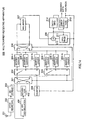
- a multicarrier transmitting apparatus 300 of this embodiment separates transmission bits output from the storage section 102 using a separating section 301.
- the separating section 301 separates the input bits to a separating section output 1 and a separating output section 2 every two bits, and supplies them to the input terminals of a following selection circuit 302, respectively.
- Output terminals of the selection circuit 302 are connected to interleavers 303-1 and 302-2, respectively, each having a different interleave pattern, through a movable contact.
- the selection circuit 302 performs selection of the interleavers 303-1 and 302-2 that supply an input bit sequence according to a count value (namely, the number of retransmissions) from a counter 305.
- a count value namely, the number of retransmissions
- Outputs of the interleavers 303-1 and 302-2 are supplied to the input terminals of a following selection circuit 304, respectively.
- Output terminals of the selection circuit 304 are connected to two input terminals of a multiplexing section 306 through a movable contact, respectively.
- the selection circuit 304 performs selection of input terminals of the multiplexing section 306 that supplies the outputs of the interleavers 303-1 and 302-2 according to a count value (namely, the number of retransmissions) from the counter 305.
- the multiplexing section 306 time multiplexes bit sequences of two systems input from the two input terminals, thereby converting them to one bit sequence to output it. At this time, bits are alternately selected by two bits and output such that the two bits supplied to the first input terminal are first output and the two bits supplied to the second input terminal are next output.
- the multiplexing section 306 outputs a bit sequence including 3, 4, 1, 2, 7, 8, 5, 6, ..., n2, n3, n0 and n1 in order as multiplexing section outputs (additionally, in FIG.9, though the bit array that ignores interleave processing using the interleavers 303-1 and 302-2 is used in order to simplify the explanation, each bit is actually interleaved).
- FIG.10 illustrates the array of bits that are actually output from the multiplexing section 306.
- bits to be allocated to each symbol are also interchanged in addition to the fact that the high-order bits and low-order bits are interchanged.
- each bit is placed on the different subcarrier at the initial transmitting time and the retransmitting time, enabling to surely obtain time diversity effect by retransmission in connection with each bit.
- FIG.12 illustrates a configuration of a multicarrier receiving apparatus 400 that receives a signal transmitted from the multicarrier transmitting apparatus 300 (FIG.7) and demodulates it.
- the multicarrier transmitting apparatus 400 inputs a despread signal to an M-ary demodulating section 401.
- the M-ary demodulating section 401, a separating section 402, a selection circuit 403, deinterleavers 404-1, 404-2, a selection circuit 405, and a multiplexing section 406 perform basically reverse processing of the corresponding sections of the multicarrier transmitting apparatus 300.
- the M-ary demodulating section 401, the separating section 402, the selection circuit 403, the deinterleavers 404-1, 404-2, the selection circuit 405, and the multiplexing section 406 perform reverse processing of the M-ary demodulating section 107, the multiplexing 306, the selection circuit 304, the deinterleavers 303-1, 303-2, the selection circuit 302, and the separating section 301, respectively. Consequently, the same bit sequence as the bit sequence input to the separating section 307 (FIG.7) except for deterioration in transmission is restored and output from the multiplexing section 406.
- the relevant high-order bits and low-order bits are interleaved with interleave patterns each being different for each retransmission and subcarriers that locate the bits are interchanged for each retransmission.
- This enables to further increase time diversity effect by retransmission in connection with each bit in addition to the effect of Embodiment 1. As a result, it is possible to improve the error rate characteristic after packet combining.
- the separating section 301 the selection circuit 302, the interleavers 303-1, 303-2, the selection circuit 304, and the multiplexing section 306, it is possible to interchange the high-order bits and low-order bits for each retransmission and interchange bits forming one symbol for each retransmission without changing a configuration of constellation mapping of the M-ary modulating section 107. This enables to implement a simple apparatus configuration.
- a multicarrier transmitting apparatus 500 of this embodiment interleaves the high-order bits and low-order bits separated by the separating section 301 with the respective independent interleave patterns. Since this enables to increase variations in the high-order bits and low-order bits greater compared to Embodiment 2, it is possible to further improve time diversity effect by retransmission in connection with each bit and more raise improvement effect of the bit error rate characteristic by retransmission.
- the high-order bits and low-order bits separated by the separating section 301 are input to a selection section 501 and distributed to a selection section 502 and a selection circuit 503, respectively, according to a count value of a counter 507 (namely, the number of retransmissions).
- Interleavers 504-1, 504-2, ..., 504-N, each having a different interleave pattern are provided to the output terminals of the selection section 502, and interleavers 505-1, 505-2, ..., 505-N, each having a different interleave pattern, are provided to the output terminals of the selection circuit 503.
- the selection circuits 502 and 503 select interleavers 504-1, 504-2, ..., 504-N, 505-1, 505-2, ..., 505-N that supply data according to the count value of the counter 507. Consequently, the high-order bits and low-order bits are interleaved with interleave patterns that are completely different from each other independently for each retransmission.
- the interleaved high-order bits and low-order bits are input to the multiplexing section 306 through the selection section 506.
- the high-order bits and low-order bits input to the input terminals of the multiplexing section 306 through the selection section 506 are interchanged for each retransmission, so that the high-order bits and low-order bits to be handled by the M-ary modulating section 107 are interchanged for each retransmission.
- FIG.14 illustrates a configuration of a multicarrier receiving apparatus 600 that receives a signal transmitted from the multicarrier transmitting apparatus 500 and demodulates it.
- the multicarrier transmitting apparatus 600 inputs an M-ary modulated signal to the separating section 402.
- the separating section 402, a selection section 601, a selection section 602, a selection section 603, deinterleavers 604-1, 604-2, ... 604-N, deinterleavers 605-1, 605-2, ... 605-N, a selection section 606, and a multiplexing section 607 perform basically reverse processing of the corresponding sections of the multicarrier transmitting apparatus 500.
- the separating section 402, the selection section 601, the selection section 602, the selection section 603, the deinterleavers 604-1, 604-2, ... 604-N, the deinterleavers 605-1, 605-2, ... 605-N, the selection circuit 606, and the multiplexing section 607 perform reverse processing of the multiplexing section 306, the selection section 506, the selection section 502, the selection section 503, the interleavers 504-1, 504-2, ... 504-N, the interleavers 505-1, 505-2, ... 505-N, the selection section 501, and the separating section 301, respectively. Consequently, the same bit sequence as the bit sequence input to the separating section 301 except for deterioration in transmission is output from the multiplexing section 607.
- the high-order bits and low-order bits separated by the separating section 301 are interleaved with interleave patterns each being independent, thereby making it possible to increase variations in the high-order bits and low-order bits greater compared to Embodiment 2 and further improve time diversity effect by retransmission in connection with each bit.
- the bits forming one M-ary modulated symbol are varied for each of the high-order bits and low-order bits by every retransmission, it is possible to reduce the probability that the reception level of the same bit will decrease even if the reception level of the same bit decreases at the previous transmission and the next transmission (retransmission). As a result, it is possible to more raise improvement effect of the bit error rate characteristic by retransmission.
- the high-order bits and low-order bits separated by the separating section 301 are interleaved with each independent interleave pattern, thereby enabling to easily restore each bit sequence on the receiving side.
- the receiving side can restore the original bit sequence by simply performing the reverse processing of the transmitting side for each of the high-order bits and low-order bits.
- the high-order bits and low-order bits separated by the separating section 301 are interleaved with the interleave patterns each being independent of each other, thereby enabling to easily restore each bit sequence on the receiving side.
- the receiving side can restore the original bit sequence by simply performing reverse processing of the transmitting side for each of the high-order bits and low-order bits.
- Embodiment 1 explained the case in which the sequence converting section 104 was provided to perform interchange processing of the high-order bits and low-order bits at the M-ary modulating time every retransmission
- Embodiment 2 explained the case in which the separating section 301, the interleavers 303-1, 303-2, the selection section 304, and the multiplexing section 306 were provided to perform bit interleave processing that is different for each retransmission and perform interchange processing of the high-order bits and low-order bits.
- the present invention is not limited to this and the function of bit interleaving and the function of interchanging the high-order bits and low-order bits may be provided to the interleavers.
- a multicarrier transmitting apparatus 700 of this embodiment includes the plurality of interleavers 701-1, 701-2, ..., 702-N, each having the function of interchanging the high-order bits and low-order bits at the M-ary modulating time and a different interleave pattern.
- the multicarrier transmitting apparatus 700 selects any one of interleavers 701-1, 701-2, ..., 702-N to which transmission data is supplied according to the number of retransmissions using a selection circuit 701. This enables to achieve the same effect as explained in Embodiments 1 and 2 by the configuration as illustrated in FIG.15.
- a multicarrier signal transmitted from the multicarrier transmitting apparatus 700 illustrated in FIG.15 can be received and modulated by a multicarrier receiving apparatus 800 configured as in FIG.16.
- the multicarrier receiving apparatus 800 inputs a signal demodulated by an M-ary demodulating section 801 to selection section 802.
- a selecting section 802, deinterleavers 803-1, 803-2, ..., 803-N perform basically reverse processing of the corresponding sections of the multicarrier transmitting apparatus 700.
- the M-ary demodulating section 801, the selecting section 802, and the deinterleavers 803-1, 803-2, ..., 803-N perform reverse processing of the M-ary modulating section 107, the selecting section 701, and interleavers 702-1, 702-2, ..., 702-N, respectively. Consequently, the same bit sequence as the bit sequence input to the selecting section 701 on the transmitting side except for deterioration in transmission is output from the deinterleavers 803-1, 803-2, ..., 803-N.
- Embodiments 1 to 3 explained the case in which 16QAM was used as M-ary modulation.
- the present invention is not limited to this, and may be applied to a case in which, for example, 64QAM, 16PSK and the like are used. To sum up, this may be widely applied to the case of using M-ary modulation in which high-order bits where a transmission error does not easily occur and low-order bits where a transmission error easily occurs are present.
- OFDM transmitting section 109 although not specifically explained in the aforementioned Embodiments 1 to 3, the same effect as explained in the aforementioned embodiments can be obtained even if the spread chip is spread in a frequency axial direction or time axial direction. Still furthermore, the same effect can be obtained even in the multicarrier transmission that performs no spreading.
- Embodiments 1 to 3 explained the case in which the counter was provided on the receiving side to count a NACK signal, thereby detecting what number of the retransmission signals a currently received signal was. However, it is possible to detect what number of the retransmission signals the currently received signal is based on a transmission number signal sent from the transmitting side.
- a detecting section that detects the reception level of each subcarrier is provided to the transmitting side or the receiving side and an interleave pattern is selected at the time of retransmission such that the same bit is prevented from being located on the subcarrier with a low reception level based on the detection result, thereby making it possible to surely prevent the reception level of the same bit from being decreased continuously at the previous transmission and the next transmission (retransmission), so that the error rate characteristic can be further improved.
- Embodiments 1 to 3 explained the case in which the present invention was implemented by hardware. However, the same function as the embodiments may be implemented by a program.
- This embodiment proposes an apparatus and method that raises improvement effect of the bit error rate characteristic by retransmission when the multicarrier communication is combined with the multicarrier communication technique such as MIMO (MultiInput MultiOutput) and the like.
- MIMO MultiInput MultiOutput
- the diversity technique is a technique that combines a plurality of received signals including the same information to improve the error rate characteristic.
- the transmission diversity a signal is transmitted to the same communication counterpart from two antennas (branches) whose fading correlation therebetween is low, thereby enabling to perform high quality reception by diversity effect without making the configuration of the apparatus on the receiving side complicated.
- the inventors of the present invention considered that when an error occurred in received data, the transmission diversity effect was not able to be improved even if transmission was performed with the same subcarrier, but the correlation differed at transmission diversity for each subcarrier and this could be used to improve the transmission diversity effect.
- the feature of the present embodiment is that in the multicarrier communication to which transmission diversity (multiahtenna) is applied, when an error occurs in received data, a subcarrier that transmits data is changed to perform retransmission, thereby increasing the chance that reduces the correlation between the branches to increase the diversity gains and improve a throughput.
- transmission diversity multiahtenna
- FIG.17 is a block diagram illustrating a configuration of a multicarrier communication apparatus according to Embodiment 4.
- a multicarrier communication apparatus 1000 of FIG.17 includes a radio receiving section 1001, a counter 1002, an encoder 1003, a storage section 1004, a modulator 1005, a transmission diversity encoder 1006-1, a transmission diversity encoder 1006-2, a mapping controller 1007, a mapping device 1008-1, a mapping device 1008-2, an interleaver controller 1009, an interleave section 1010-1, an interleave section 1010-2, an IFFT section 1011-1, an IFFT section 1011-2, a radio transmitting section 1012-1, and a radio transmitting section 1012-2.
- the radio receiving section 1001 converts a received radio signal to a baseband frequency to modulate, and extracts an ACK signal or NACK signal and output it to the counter 1002.
- the counter 1002 counts the number of times the NACK signal is received in unit of transmitting data, and outputs the number of times to the storage section 1004, the mapping controller 1007, and the interleaver controller 1009.
- the encoder 1003 error correction coding on transmitting data and outputs it to the storage section 1004.
- the storage section 1004 stores coded data. Then, when receiving a counter value (for example, "1") indicating an initial transmission from the counter 1002, the storage section 1004 outputs next coded data to the modulator 1005. Moreover, when receiving a counter value (for example, a value except for "1") indicating a retransmission from the counter 1002, the storage section 1004 outputs previously stored data to the modulator 1005.
- the modulator 1005 modulates data and outputs it to the transmission diversity encoder 1006-1 and the transmission diversity encoder 1006-2.
- the transmission diversity encoder 1006-1 directly outputs an input data sequence to the mapping device 1008-1.
- the transmission diversity encoder 1006-2 obtains a complex conjugate of data, rearranges the order of two adjacent symbols, performs computation of X(-1) to one symbol, and outputs it to the mapping device 1008-2.
- the mapping controller 1007 decides a subcarrier that maps data based on the number of times the NACA signal is received in unit of transmitting data, and directs it to the mapping device 1008-1 and the mapping device 1008-2.
- the subcarrier directed by the mapping controller 1007 differs depending on the number of times the NACK signal is received.
- the mapping device 1008-1 maps phase and amplitude according to transmitting data to accommodate the subcarrier directed by the mapping controller 1007, and outputs the mapping values to the interleave section 1010-1.
- the mapping device 1008-2 maps phase and amplitude according to transmitting data to accommodate the subcarrier directed by the mapping controller 1007, and outputs the mapping values to the interleave section 1010-2.
- the interleaver controller 1009 directs an interleave pattern to the interleave section 1010-1 and the interleave section 1010-2 based on the number of times the NACK signal is received in unit of transmitting data.
- the interleave pattern directed by the interleaver controller 1009 differs depending on the number of times the NACK signal is received.
- the interleave section 1010-1 includes a selection circuit 1021 and interleavers 1022-1 to 1022-n, and changes the interleave pattern to rearrange data according to instructions from the interleaver controller 1009. Then, the interleave section 1010-1 outputs the rearranged data to the IFFT section 1011-1.
- the selection circuit 1021 outputs data to an interleaver of interleavers 1022-1 to 1022-n that performs rearranging with the interleave pattern corresponding to instructions from the interleaver controller 1009.
- the interleavers 1022-1 to 1022-n rearrange the order of data with different interleave patterns, and output rearranged data to the IFFT section 1011-1, respectively.
- the selection circuit 1021 outputs data to the interleaver 1022-1 at a first transmitting time, the selection circuit 1021 outputs data to the interleaver 1022-2 at a first retransmitting time, and the selection circuit 1021 outputs data to the interleaver 1022-3 at a second retransmitting time. Then, when success in data transmission is attained and next data is transmitted, the selection circuit 1021 outputs data again to the interleaver 1022-1.
- the interleave section 1010-2 changes the interleave pattern to rearrange data according to instructions from the interleaver controller 1009. Then, the interleave section 1010-2 outputs rearranged data to the IFFT section 1011-2.
- the IFFT section 1011-1 orthogonally transforms data rearranged by the interleave section 1010-1 so as to transform data of the frequency domain into signal of the time domain, and outputs it to the radio transmitting section 1012-1.
- the IFFT section 1011-2 orthogonally transforms data rearranged by the interleave section 1010-2 so as to transform data of the frequency domain into signal of the time domain, and outputs it to the radio transmitting section 1012-2.
- the IFFT section 1011-1 and IFFT section 1011-2 perform an inverse fast Fourier transform on data.
- the radio transmitting section 1012-1 transforms a signal output from the IFFT section 1011-1 to a radio frequency and transmits it.
- the radio transmitting section 1012-2 transforms a signal output from the IFFT section 1011-2 to a radio frequency and transmits it.
- FIG's.18 to 23 are views each illustrating one example of a symbol array.
- a vertical axis indicates a subcarrier frequency and a horizontal axis indicates time.
- FIGS. 18, 19, and 20 are views each illustrating a symbol array transmitted from the radio transmitting section 1012-1.
- FIGS. 21, 22, and 23 are views each illustrating a symbol array transmitted from the radio transmitting section 1012-2.
- a branch that transmits a signal from the radio transmitting section 1012-1 is a branch #1 and that a branch that transmits a signal from the radio transmitting section 1012-2 is a branch #2.
- FIG's. 18 and 21 are views each illustrating a symbol array when data is first transmitted.
- FIGS. 19 and 22 are views each illustrating a symbol array when the same data is retransmitted.
- FIGS. 20 and 23 are views each illustrating a symbol array when a second retransmission is performed.
- the multicarrier communication apparatus 1000 transmits symbols S0, S1, S2 and S3 in order by a subcarrier with a frequency f6 from the radio transmitting section 1012-1, and transmits symbols S4, S5, S6 and S7 in order by a subcarrier with a frequency f3 therefrom.
- the multicarrier communication apparatus 1000 transmits symbols -S1*, S0*, -S3* and S2* in order by a subcarrier with a frequency f6 from the radio transmitting section 1012-1, and transmits symbols -S5*, S4*, -S7* and S6* in order by a subcarrier with a frequency f3 therefrom.
- two branches #1 and #2 have a case in which the correlation therebetween is high and a case in which the correlation therebetween is low depending on the subcarrier to be transmitted. Then, when the correlation between the branches is high, transmission diversity effect cannot be sufficiently obtained.
- the multicarrier communication apparatus 1000 of this embodiment retransmits data using a subcarrier different from one used at the first data transmitting time when an error occurs on the receiving side.
- data transmitted using the subcarrier with f3 is transmitted at f5 at the retransmitting time and data transmitted using the subcarrier with f6 is transmitted at f2 at the retransmitting time.
- the multicarrier communication apparatus 1000 transmits symbols S0, S1, S2 and S3 in order by the subcarrier with a frequency f2 from the radio transmitting section 1012-1, and transmits symbols S4, S5, S6 and S7 in order by the subcarrier with a frequency f5 therefrom.
- symbols -S1*, S0*, -S3* and S2* are transmitted in order by the subcarrier with a frequency f2 from the radio transmitting section 1012-2 and symbols -S5*, S4*, -S7* and S6* are transmitted in order by the subcarrier with a frequency f5 therefrom.
- the multicarrier communication apparatus 1000 of this embodiment further transmits data at a frequency different from the frequency of the subcarrier used at the retransmitting time. For example, as illustrated in FIGS. 20 and 23, data transmitted using the subcarrier with f2 is transmitted at f4 at the retransmitting time and data transmitted using the subcarrier with f5 is transmitted using the subcarrier at f2 at the retransmitting time.
- FIG.24 is a block diagram illustrating a configuration of a receiving system of a multicarrier communication apparatus according to Embodiment 4.
- a multicarrier communication apparatus 2000 of FIG.24 includes a radio receiving section 2001, an FFT section 2002, a deinterleave section 2003, a demapping device 2004, a transmission diversity decoder 2005, a combining circuit 2006, a demodulator 2007, a decoder 2008, an error detector 2009, a counter 2010, a deinterleaver controller 2011, a demapping controller 2012, and a radio transmitting section 2013.
- the radio receiving section 2001 receives a radio signal to convert to a baseband frequency, and outputs the obtained baseband signal to the FFT section 2002.
- the FFT section 2002 orthogonally transforms the baseband signal so as to transform data of the frequency domain to data of the time domain, and outputs it to the deinterleave section 2003.
- the deinterleave section 2003 includes a selection circuit 2031 and deinterleavers 2031-1 to 2032-n, changes a deinterleave pattern to rearrange data according to instructions from the deinterleaver controller 2011, and returns data transmitted by the multicarrier communication apparatus 1000 to the original order. Then, the deinterleave section 2003 outputs rearranged data to the demapping section 2004.
- the selection circuit 2031 outputs data to any one. of the deinterleavers 2032-1 to 2032-n according to the number of NACK times.
- the deinterleavers 2032-1 to 2032-n rearrange the order of data with different deinterleave patterns, respectively.
- the demapping device 2004 demaps rearranged data and transmits it to the transmission diversity decoder 2005.
- the transmission diversity decoder 2005 decodes demapped data and outputs it to the combining circuit 2006.
- the combining circuit 2006 When data is stored and the data is retransmitted, the combining circuit 2006 combines data combing result up to the previous reception with the currently received data, and outputs it to the demodulator 2007. More specifically, the combining circuit 2006 includes a combining device 2041 and a storage section 2042.
- the combining section 2041 combines data output from the transmission diversity decoder 2005 with data stored in the storage section 2042, and outputs it to the storage section 2042 and the demodulator 2007.
- the storage section 2042 stores a symbol output from the combining device 2041. Moreover, when receiving an ACK signal from the error detector 2009, the storage section 2042 resets the storage contents.
- the demodulator 2007 demodulates data and outputs it to the decoder 2008.
- the decoder 2008 decodes data and outputs it to the error detector 2009.
- the error detector 2009 detects whether there is an error in data. Then, when there is an error in data, the error detector 2009 transmits a NACK signal to the combining circuit 2006, the counter 2010 and the radio transmitting section 2013, and transmits an ACK when there is no error therein.
- the counter 2010 counts the number of times the NACK signal is received for each data to be received, and outputs the number of times to the deinterleaver controller 2011 and the demapping controller 2012.
- the deinterleaver controller 2011 directs a deinterleave pattern to the deinterleave section 2003 based on the number of times the NACK signal is received in unit of receiving data, namely, the number of times an error occurs in data.
- the deinterleave pattern directed by the deinterleaver controller 2011 differs depending on the number of times the NACK signal is received, and corresponds to a pattern that is used to deinterleave data interleaved by the interleaver controller 1009.
- the demapping controller 2012 decides a subcarrier that demaps data based on the number of times the NACA signal is received in unit of transmitting data, and directs it to the demapping device 2004.
- the subcarrier directed by the demapping controller 2012 differs depending on the number of times the NACK signal is received, and corresponds to a mapping pattern directed by the mapping controller 1007.
- the radio transmitting section 2013 modulates the ACK signal or NACK signal to convert to a radio frequency, and transmits it.
- the multicarrier communication apparatus in a case where transmission space diversity is performed using a plurality of antennas, when an error occurs in data received by the receiving side, a subcarrier to be transmitted by the transmitting side is changed to retransmit data, so that a correlation value between branches is changed for each retransmission to reduce an average of this correlation value, thereby making it possible to increase gains of transmission space diversity and improve the entire throughput of communication.
- an interleave pattern that is used to rearrange data to be transmitted by the transmitting side is changed to make it possible to reduce a fading correlation value in time at the time of retransmitting, so that diversity effect is increased to improve the entire throughput of communications.
- the interleave pattern is fixed when data is rearranged at the first transmitting time, however, next data may be rearranged at the first transmitting time using the interleave pattern employed when success in data transmission was previously attained. For example, when correct data is transmitted at the second retransmission, next transmitting data is rearranged to perform first transmission using the interleave pattern employed at the second retransmission.
- next data may be rearranged at the first transmitting time using the interleave pattern employed when success in data transmission was previously attained, thereby enabling to transmit data using the interleave pattern suitable for the circumstances of the propagation path and improve the entire throughput of communication under even an environment where a burst error occurs.
- a fast Fourier transform is used, however, any transform may be used if an orthogonal transform is used.
- a discrete cosine transform, a discrete Fourier transform, and the like may be used.
- the number of branches of the transmission diversity is not limited to two, and any number of branches may be possible if multiple branches are used.
- the multicarrier communication apparatus 2000 is configured such that the counter 2010 is provided to count the number of transmissions.
- the number of transmissions of the relevant transmitting data is sent to the multicarrier communication apparatus 2000 from the multicarrier communication apparatus 1000.
- the correlation between the branches is reduced by the mapping of this embodiment to make it possible to obtain transmission diversity effect.
- the multicarrier communication apparatus 2000 is configured such that packet combining is performed by the combining circuit 2006 at the retransmitting time and thereafter modulation is performed by the demodulator 2007.
- packet combining is performed by the combining circuit 2006 at the retransmitting time and thereafter modulation is performed by the demodulator 2007.
- modulation is performed by the demodulator 2007 and thereafter demodulated outputs are combined by the combing circuit 2006.
- the present invention is not limited to the aforementioned embodiments and various modifications may be implemented.
- the aforementioned embodiments explained the case in which the respective functions were implemented by a hardware configuration.
- the present invention is not limited to these, and the aforementioned multicarrier communication method may be executed as software.
- a program that executes the aforementioned multicarrier communication method is prestored in a ROM (Read Only Memory) and the program may be operated by a CPU (Central Processor Unit).
- ROM Read Only Memory
- CPU Central Processor Unit
- the program that executes the aforementioned multicarrier communication method is stored in a computer readable storage medium, the program stored in the storage medium is recoded on a RAM (Random Access Memory) of the computer, and the computer may be operated according to the program.
- a RAM Random Access Memory
- a correlation value between the branches is changed at the first transmission and the retransmission to reduce an average of the correlation value, thereby making it possible to increase gains of transmission space diversity and improve the entire throughput of communications.
- M-ary modulation when M-ary modulation is provided to transmission data and modulated symbol is multicarrier transmitted, high-order bits where an error easily occurs and low-order bits where an error does not easily occur are interchanged for each retransmission and M-ary modulation is provided thereto, and bit interleave processing is performed such that bits forming one symbol differ for each retransmission, thereby making it possible to implement a multicarrier communication apparatus and method that can improve an error rate characteristic by retransmission.
- a subcarrier that transmits data is changed to perform retransmission, thereby making it possible to boost the chance that reduces the correlation between the branches and increase the diversity gains at the time of transmission and packet combining concurrently, so that the throughput characteristic can be improved.
- the present invention can be applied to a radio base station apparatus and a communication terminal apparatus that perform multicarrier communications such as an OFDM (Orthogonal Frequency Division Multiplexing) and the like.
- OFDM Orthogonal Frequency Division Multiplexing
Landscapes
- Engineering & Computer Science (AREA)
- Signal Processing (AREA)
- Computer Networks & Wireless Communication (AREA)
- Physics & Mathematics (AREA)
- Probability & Statistics with Applications (AREA)
- Theoretical Computer Science (AREA)
- Quality & Reliability (AREA)
- Detection And Prevention Of Errors In Transmission (AREA)
- Error Detection And Correction (AREA)
- Mobile Radio Communication Systems (AREA)
Abstract
A sequence converting section 104 interchanges
high-order bits where an error does not easily occur
and low-order bits where an error easily occurs that
are used by an M-ary modulating section 105 for each
retransmission. The M-ary modulating section 105
performs M-ary modulation using the high-order bits
and low-order bits interchanged for each
retransmission. An M-ary modulated symbol is
interleaved with an interleave pattern being
different for each retransmission, and multicarrier
transmitted via an OFDM transmitting section 109.
Description
The present invention relates to a
multicarrier communication apparatus and
multicarrier communication method that adopts a
retransmission technique to improve an error rate.
Conventionally, there is proposed a
multicarrier communication system that combines a
packet obtained at initial transmission with a
retransmitted packet to decode, thereby improving
an error rate characteristic caused at a decoding
time on a receiving side. Then, conventionally,
for the purpose of improving the throughput of data,
various kinds of contrivances have been proposed to
achieve a desired error rate with a small number of
retransmissions.
Particularly, in the multicarrier
communication system, a reception level differs for
each subcarrier because of frequency-selective
fading. Accordingly, the reception level of a
signal on which a subcarrier with a certain
frequency is superimposed becomes high but the
reception level of the signal on which another
subcarrier is superimposed becomes low. As a
result, the error rate of the signal on which a
subcarrier with a low reception level does not
easily achieve a desired value, so that the number
of retransmissions increases.
In consideration of this point, there are
methods disclosed in Unexamined Japanese Patent
Publication Nos. 2001-60934 and 2000-269929. In
these methods, an interleave pattern is changed for
each retransmission to vary a subcarrier that
locates a symbol for each retransmission. As a
result, the signal level of each symbol can be
unified at a packet combining time to make it
possible to improve the error rate characteristic.
By the way, according to the conventionally
proposed method that changes the interleave pattern
for each retransmission, since variations in
transmission symbols can be, indeed, made greater
by interleave processing, a symbol with an extremely
low error rate can be reduced to enable to improve
the throughput of data effectively.
However, in recent years, it has been demanded
that a large capacity of data such as image data is
transmitted at high speed, and in order to achieve
this, it is needed to further improve the error rate
characteristic to reduce the number of
retransmission times, thereby much more improving
the throughput.
An object of the present invention is to more
increase improvement effect of an error rate
characteristic by retransmission to improve a
throughput characteristic in multicarrier
communications.
This object can be attained by interchanging
high-order bits where an error easily occurs and
low-order bits where an error does not easily occur
for each retransmission to provide M-ary modulation
when M-ary modulation is provided to transmission
data to perform multicarrier transmission to a
modulated symbol. Moreover, bit interleave
processing is performed such that bits forming M-ary
modulated one symbol differ for each retransmission,
thereby making it possible to further improve the
throughput characteristic.
In other words, even if the reception level of
the same symbol reduces at the previous transmission
and the next transmission (retransmission), this
enables to reduce a probability that the reception
level of the same bit will continuously become small
to improve time diversity effect by retransmission
on the receiving side. As a result, since the error
rate characteristic after packet combining on the
receiving side can be improved, it is possible to
reduce the number of times of retransmissions and
improve the throughput of data.
The following will specifically explain
embodiments of the present invention with reference
to the accompanying drawings.
In FIG.1, 100 indicates a configuration of a
multicarrier transmitting apparatus as a whole
according to Embodiment 1 of the present invention.
The multicarrier transmitting apparatus 100 is used
as a transmission system of a multicarrier
communication apparatus according to the present
invention.
The multicarrier transmitting apparatus 100 is
provided in a radio base station apparatus and a
communication terminal apparatus.
The multicarrier transmitting apparatus 100
performs M-ary modulation processing to
transmission data, performs spread processing to a
symbol obtained by modulation, superimposes a chip
obtained by spreading on a plurality of subcarriers
orthogonal to each other, and transmits it. Namely,
the multicarrier transmitting apparatus 100 in this
Embodiment sends transmission data by OFDM
(Orthogonal Frequency Division Multiplexing) - CDMA
(Code Division Multiple Access).
The multicarrier transmitting apparatus 100
codes transmission data using a coding section 101
and sends the coded data to a storage section 102.
The storage section 102 is read and controlled based
on a count value of a counter 103. Here, the counter
103 increments the count value every time when a NACK
signal (repeat request signal) is sent from a
receiving side, and resets the count value to 0 when
an ACK signal is sent. The storage section 102 sends
data stored every time when the count value is
incremented to the sequence converting section 104
(namely, retransmission data is transmitted). On
the other hand, when the count value becomes 0, data
from the coding section 101 is directly transmitted
to the sequence converting section 104 (namely,
initial transmission data is transmitted).
The sequence converting section 104
interchanges the order of high-order bits where an
error does not easily occur and low-order bits where
an error easily occurs, both which are modulated by
a next M-ary modulating section 105, every time when
the count value from the counter 103 is incremented.
The M-ary modulating section 105 modulates a
plurality of bits of data input from the sequence
converting section 104 to one symbol. In this
embodiment, the M-ary modulating section 105
performs 16QAM (Quadrature Amplitude Modulation) to
the input data to modulate four bits to one symbol.
An explanation will be next given of processing
of the sequence converting section 104 and that of
the M-ary modulating section 105 using FIG.2. Here,
FIG.2(A) is a view illustrating an array of bits
input to the sequence converting section 104.
FIG.2(B) is a view illustrating an array of bits
forming each symbol at an initial transmitting time.
FIG.2(C) is a view illustrating an array of bits
forming each symbol at a retransmitting time (first
retransmitting time). FIG.2(D) is a view
illustrating an array of bits output from the
sequence converting section 104 at a retransmitting
time (first retransmitting time).
Here, in FIG.'s. 2 (B) and 2(C), b0 and b1 show
high-order bits where an error does not easily occur
when being 16QAM modulated and b2 and b3 show
low-order bits where an error easily occurs. As is
obvious from FIG.2, the high-order bits and
low-order bits are interchanged by the sequence
converting section 104 at the initial transmitting
time and the retransmitting time. Referring to,
for example, symbol No. 1., bits 1 and 2 are placed
as high-order bits and bits 3 and 4 are placed as
low-order bits at the initial transmitting time
(FIG.2(B)), while bits 3 and 4 are placed as
high-order bits and bits 1 and 2 are placed as
low-order bits at the retransmitting time
(FIG.2(C)).
The M-ary modulated symbol is input to a
selection circuit 106. A plurality of interleavers
107-1, 107-2, ... 107-N, each having a different
interleave pattern, is connected to an output side
of the selection circuit 106. The selection
circuit 106 selects interleavers 107-1, 107-2, ...
107-N to have the modulated symbol inputted
according to the count value from the counter 103.
Accordingly, symbols, each having a different array
order for each retransmission, are sent to a
spreading section 108.
The spreading section 108 multiplies the input
symbol by a spreading code and thereby spreads the
symbol to a chip unit. An OFDM transmitting section
109 includes an IFFT (Inverse Fast Fourier Transform
circuit) and a radio transmitting circuit, and
superimposes a plurality of subcarriers orthogonal
to each other on a chip obtained by spreading. A
signal subjected to OFDM transmission processing is
transmitted through an antenna 110.
FIG.3 shows a configuration of a multicarrier
receiving apparatus 200 that receives a
multicarrier signal transmitted from the
multicarrier transmitting apparatus 100. The
multicarrier receiving apparatus 200 is used as a
receiving system of the multicarrier communication
apparatus of the present invention. The
multicarrier receiving apparatus 200 inputs a
received signal to an OFDM receiving section 202
through an antenna 201.
The OFDM receiving section 202 includes a radio
receiving section and an FFT (Fast Fourier transform
circuit), and extracts each chip superimposed on the
plurality of subcarriers. A despreading section
203 despreads an input signal using a spreading code,
so that an unspread symbol is restored and the
restored symbol is transmitted to a selection
circuit 204.
A plurality of deinterleavers 206-1, 206-2, ...
206-N, each having a different deinterleave pattern,
is connected to an output side of the selection
circuit 204. Each of deinterleavers 206-1, 206-2,
... 206-N returns each symbol to the original array
by performing reverse processing of the
interleavers 107-1, 107-2, ... 107-N (FIG.1) on the
transmitting side.
The selection circuit 204 selects the
deinterleavers 206-1, 206-2, ... 206-N to have an
input signal outputted according to a count value
from a counter 205. Here, the counter 205 is
incremented every time when a NACK signal is input
similar to the counter 103 on the transmitting side
(FIG.1). In other words, between the multicarrier
transmitting apparatus 100 and the multicarrier
receiving apparatus 200, the interleavers 107-1,
107-2, ... 107-N (FIG.1) and the deinterleavers 206-1,
206-2, ... 206-N are selected according to the number
of retransmissions, so that the array of symbol is
returned to the original by the deinterleavers 206-1,
206-2, ... 206-N.
The symbol returned to the original array by
the deinterleavers 206-1, 206-2, ... 206-N is input
to an M-ary demodulating section 207. The M-ary
demodulating section 207 performs demodulation
processing corresponding to the M-ary modulating
section 105 (FIG.1) to demodulate four-bit data from
one symbol.
A sequence converting section 208 performs
sequence conversion that is reverse to the sequence
converting section 104 (FIG.1) on the transmitting
side according to the number of retransmissions.
More specifically, the input bits are directly
output with the array unchanged at the time of
receiving the initially transmitted data, while the
arrays of the high-order bits and low-order bits are
interchanged for each retransmission when the
retransmitted signal is received. Consequently,
the signal with the same bit array as the transmitted
data can be obtained. An output of the sequence
converting section 208 is input to a combining
circuit 209 that combines retransmitted packets.
The combining circuit 209 includes a storage
section 211 and an adding section 210, and packet
data stored in the storage section 211 up to the
current retransmission and currently retransmitted
packet data are added by an adding section 210. For
example, when currently input packet data is packet
data at a second retransmission, combined packet
data, including data stored in the storage section
211 at the initial transmission and data at the first
retransmission, is combined with currently
retransmitted packet data.
Combined packet data is decoded by a decoding
section 212 and an error detecting section 213
perform error detection such as CRC (Cyclic
Redundancy Check). Accordingly, decoded data is
output from the error detecting section 213 and an
ACK signal is output when CRC is OK and a NACK signal
is output when CRC is NG. ACK/NACK signals are sent
to the counter 205 and also to the multicarrier
transmitting apparatus 100 (FIG.1).
An explanation will be next given of an
operation of this embodiment. In this embodiment,
the high-order bits and low-order bits at an M-ary
modulation time are interchanged by the
multicarrier transmitting apparatus 100 for each
retransmission to make it possible to improve an
error rate in bit unit on the receiving side. First
of all, this will be explained using FIGS. 4, 5, and
6.
FIG.4 shows a mapping position on an I-Q plane
of each symbol by 16QAM. At the time of demodulation,
regarding the high-order two bits, a decision
threshold value with a width il in the figure is used
as an in-phase component and a decision threshold
value with a width q1 in the figure as a quadrature
component, and soft decision processing is
performed. On the other hand, regarding the
low-order two bits, a decision threshold value with
a width i2 is used as an in-phase component and a
decision threshold value with a width q2 is used as
a quadrature component, and soft decision
processing is performed. As is obvious from the
figure, since widths i2 and q2 of the decision
threshold values of the low-order two bits are
narrower than widths i1 and q1 of the decision
threshold values of the high-order two bits, an
error easily occurs as compared with the high-order
two bits when symbol phase and amplitude are varied
by a propagation path.
FIG.5 shows a relationship between SIR (Signal
to Interference Ratio) and BER (Bit Error Rate) in
connection with the high-order two bits S0, S1 and
the low-order two bits S2, S3. As is obvious from
the figure, the high-order two bits have lower BER
when the same SIR is given.
According to this embodiment, as illustrated
in FIG.6, bits S0 and S1 are transmitted as
high-order bits with high quality at an initial
transmitting time and bits S2 and S3 are transmitted
as high-order bits with high quality at a second
transmitting time (retransmitting time). This
makes it possible to restore all bits S0', S1', S2'
and S3' having such quality that causes no error when
packet combining is performed on the receiving side.
In other words, time diversity effect can be
obtained in bit unit by retransmission and an error
rate characteristic of combined packet data can be
improved as compared with the case in which bits
transmitted as low-order bits at the initial
transmitting time are transmitted as low-order bits
at the retransmitting time.
Moreover, in this embodiment, since the M-ary
modulated symbols are interleaved with interleave
patterns each being different for each
retransmission to perform multicarrier
transmission, it can be expected that the error rate
characteristic will be improved in symbol unit. In
other words, even if a signal level of a specific
subcarrier drops by frequency-selective fading,
since there is a low probability that the same symbol
will be continuously allocated to the subcarrier,
time diversity effect can be obtained in bit unit
by retransmission and the error rate characteristic
of combined packet data can be further improved.
According to the aforementioned configuration,
in a case where M-ary modulation is performed to
transmission data and multicarrier transmission is
performed to the modulated symbol, the high-order
bits and low-order bits are interchanged for each
transmission to perform M-ary modulation, thereby
enabling to obtain time diversity effect by
retransmission in connection with each bit and
improve the error rate characteristic of combined
packet data. As a result, the number of
retransmissions can be reduced to make it possible
to improve the throughput of data.
In this embodiment, in addition to the fact that
the high-order bits and low-order bits are
interchanged for each retransmission to perform
M-ary modulation similar to Embodiment 1, bits,
which are allocated to high-order bits, and bits,
which are allocated to low-order bits, are divided
at the time of M-ary modulation, and the respective
divided bit sequences are interleaved using
interleave patterns each being different for each
retransmission.
As a result, in addition to the fact that the
high-order bits and low-order bits are interchanged
for each retransmission, bits forming one symbol due
to M-ary modulation are also interchanged for each
retransmission. Since this makes it possible to
further vary each bit (namely, upon every
retransmission, reduce a probability that the same
bit is located on the same subcarrier) seeing
between the retransmissions, time diversity effect
by retransmission can be further increased in
connection with each bit.
In FIG.7 shown by adding the same reference
numerals as those of FIG.1 to the portions
corresponding to FIG.1, a multicarrier transmitting
apparatus 300 of this embodiment separates
transmission bits output from the storage section
102 using a separating section 301. In this
embodiment, since 16QAM where four bits are used as
one symbol is performed, input bits are separated
by every two bits. More specifically, as
illustrated in FIG.8, the separating section 301
separates the input bits to a separating section
output 1 and a separating output section 2 every two
bits, and supplies them to the input terminals of
a following selection circuit 302, respectively.
Output terminals of the selection circuit 302
are connected to interleavers 303-1 and 302-2,
respectively, each having a different interleave
pattern, through a movable contact. The selection
circuit 302 performs selection of the interleavers
303-1 and 302-2 that supply an input bit sequence
according to a count value (namely, the number of
retransmissions) from a counter 305. For example,
at an initial transmitting time, the separating
section output 1 shown in FIG.8 is supplied to the
interleaver 303-1 and the separating section output
2 is supplied to the interleaver 303-2. While, at
a first retransmitting time, the separating section
output 1 is supplied to the interleaver 303-2 and
the separating section output 2 is supplied to the
interleaver 303-1.
Outputs of the interleavers 303-1 and 302-2 are
supplied to the input terminals of a following
selection circuit 304, respectively. Output
terminals of the selection circuit 304 are connected
to two input terminals of a multiplexing section 306
through a movable contact, respectively. The
selection circuit 304 performs selection of input
terminals of the multiplexing section 306 that
supplies the outputs of the interleavers 303-1 and
302-2 according to a count value (namely, the number
of retransmissions) from the counter 305.
Here, the multiplexing section 306 time
multiplexes bit sequences of two systems input from
the two input terminals, thereby converting them to
one bit sequence to output it. At this time, bits
are alternately selected by two bits and output such
that the two bits supplied to the first input
terminal are first output and the two bits supplied
to the second input terminal are next output.
An explanation will be given of the input and
output states of the multiplexing section 306 using
FIG.9. At the first transmitting time, 1, 2, 5, 6,
..., n0, and n1 as multiplexing section inputs 1 are
input to the first input terminal and 3, 4, 7, 8,
..., n2, and n3 as multiplexing section inputs 2 are
input to the second input terminal. At this time,
the multiplexing section 306 outputs a bit sequence
including 1, 2, 3, 4, 5, 6, 7, 8, ..., n0, n1, n2 and
n3 in order as multiplexing section outputs.
While, although not illustrated, at the
retransmitting time, 3, 4, 7, 8, ..., n2 and n3 as
multiplexing section inputs 1 are input to the first
input terminal, and 1, 2, 5, 6, ..., n0 and n1 as
multiplexing section inputs 2 are input to the
second input terminal. At this time, the
multiplexing section 306 outputs a bit sequence
including 3, 4, 1, 2, 7, 8, 5, 6, ..., n2, n3, n0 and
n1 in order as multiplexing section outputs
(additionally, in FIG.9, though the bit array that
ignores interleave processing using the
interleavers 303-1 and 302-2 is used in order to
simplify the explanation, each bit is actually
interleaved).
This enables the M-ary modulating section 105
to perform M-ary modulation processing in which the
high-order bits and low-order bits are interchanged
at the initial transmitting time and the
retransmitting time, resulting in obtaining the
same effect as Embodiment 1 that can prevent the
reception quality of the low-order bits from being
continuously degraded.
FIG.10 illustrates the array of bits that are
actually output from the multiplexing section 306.
As is obvious from the figure, at an initial
transmitting time shown in FIG.10(A) and a
retransmitting time shown in FIG.10(B), bits to be
allocated to each symbol are also interchanged in
addition to the fact that the high-order bits and
low-order bits are interchanged. As a result, for
example, even when each symbol is allocated to the
same subcarrier at the initial transmitting time and
the retransmitting time, each bit is placed on the
different subcarrier at the initial transmitting
time and the retransmitting time, enabling to surely
obtain time diversity effect by retransmission in
connection with each bit.
Here, the following will briefly explain the
reason why the error rate characteristic is improved
by changing the subcarrier that locates the bits at
the initial transmitting time and the
retransmitting time using FIG.11. When the same
interleave pattern # 1 is used at the initial
transmitting time and the retransmitting time, the
same data is placed on the same subcarrier at the
initial transmitting time and the retransmitting
time. For this reason, even if an initially
transmitted signal and a retransmitted signal are
combined, data allocated to the subcarrier whose
reception level drops because of
frequency-selective fading can hardly obtain
diversity effect due to the retransmission. Data
2 and 7 indicated by X in the figure correspond to
this.
On the other hand, when the same different
interleave patterns # 1 and #2 are used at the initial
transmitting time and the retransmitting time, the
same data is placed on the different subcarriers at
the initial transmitting time and the
retransmitting time. For this reason, when an
initial transmission signal and a retransmission
signal are combined, there is a high possibility
that data, which was not able to obtain a sufficient
reception level at the first transmission, will
obtain a sufficient reception level at the second
transmission. This results in obtaining diversity
effect due to the retransmission. Data 2 and 7
indicated by ○ in the figure correspond to this.
FIG.12 illustrates a configuration of a
multicarrier receiving apparatus 400 that receives
a signal transmitted from the multicarrier
transmitting apparatus 300 (FIG.7) and demodulates
it. In FIG.12 shown by adding the same reference
numerals as those of FIG.3 to the portions
corresponding to FIG.3, the multicarrier
transmitting apparatus 400 inputs a despread signal
to an M-ary demodulating section 401. Here, the
M-ary demodulating section 401, a separating
section 402, a selection circuit 403,
deinterleavers 404-1, 404-2, a selection circuit
405, and a multiplexing section 406 perform
basically reverse processing of the corresponding
sections of the multicarrier transmitting apparatus
300.
More specifically, the M-ary demodulating
section 401, the separating section 402, the
selection circuit 403, the deinterleavers 404-1,
404-2, the selection circuit 405, and the
multiplexing section 406 perform reverse processing
of the M-ary demodulating section 107, the
multiplexing 306, the selection circuit 304, the
deinterleavers 303-1, 303-2, the selection circuit
302, and the separating section 301, respectively.
Consequently, the same bit sequence as the bit
sequence input to the separating section 307 (FIG.7)
except for deterioration in transmission is
restored and output from the multiplexing section
406.
According to the aforementioned configuration,
in addition to the fact that the M-ary modulated
high-order bits and low-order bits are interchanged
for each retransmission, the relevant high-order
bits and low-order bits are interleaved with
interleave patterns each being different for each
retransmission and subcarriers that locate the bits
are interchanged for each retransmission. This
enables to further increase time diversity effect
by retransmission in connection with each bit in
addition to the effect of Embodiment 1. As a result,
it is possible to improve the error rate
characteristic after packet combining.
Moreover, by providing the separating section
301, the selection circuit 302, the interleavers
303-1, 303-2, the selection circuit 304, and the
multiplexing section 306, it is possible to
interchange the high-order bits and low-order bits
for each retransmission and interchange bits
forming one symbol for each retransmission without
changing a configuration of constellation mapping
of the M-ary modulating section 107. This enables
to implement a simple apparatus configuration.
In FIG.13 shown by adding the same reference
numerals as those of FIG.7 to the portions
corresponding to FIG.7, a multicarrier transmitting
apparatus 500 of this embodiment interleaves the
high-order bits and low-order bits separated by the
separating section 301 with the respective
independent interleave patterns. Since this
enables to increase variations in the high-order
bits and low-order bits greater compared to
Embodiment 2, it is possible to further improve time
diversity effect by retransmission in connection
with each bit and more raise improvement effect of
the bit error rate characteristic by
retransmission.
More detailed explanation will be given as
follows. The high-order bits and low-order bits
separated by the separating section 301 are input
to a selection section 501 and distributed to a
selection section 502 and a selection circuit 503,
respectively, according to a count value of a
counter 507 (namely, the number of retransmissions).
Interleavers 504-1, 504-2, ..., 504-N, each having a
different interleave pattern, are provided to the
output terminals of the selection section 502, and
interleavers 505-1, 505-2, ..., 505-N, each having a
different interleave pattern, are provided to the
output terminals of the selection circuit 503.
Then, the selection circuits 502 and 503
select interleavers 504-1, 504-2, ..., 504-N, 505-1,
505-2, ..., 505-N that supply data according to the
count value of the counter 507. Consequently, the
high-order bits and low-order bits are interleaved
with interleave patterns that are completely
different from each other independently for each
retransmission.
The interleaved high-order bits and low-order
bits are input to the multiplexing section 306
through the selection section 506. At this time,
in the same way as explained in Embodiment 2, the
high-order bits and low-order bits input to the
input terminals of the multiplexing section 306
through the selection section 506 are interchanged
for each retransmission, so that the high-order bits
and low-order bits to be handled by the M-ary
modulating section 107 are interchanged for each
retransmission.
FIG.14 illustrates a configuration of a
multicarrier receiving apparatus 600 that receives
a signal transmitted from the multicarrier
transmitting apparatus 500 and demodulates it. In
FIG.14 shown by adding the same reference numerals
as those of FIG.12 to the portions corresponding to
FIG.12, the multicarrier transmitting apparatus 600
inputs an M-ary modulated signal to the separating
section 402. Here, the separating section 402, a
selection section 601, a selection section 602, a
selection section 603, deinterleavers 604-1, 604-2,
... 604-N, deinterleavers 605-1, 605-2, ... 605-N, a
selection section 606, and a multiplexing section
607 perform basically reverse processing of the
corresponding sections of the multicarrier
transmitting apparatus 500.
More specifically, the separating section 402,
the selection section 601, the selection section 602,
the selection section 603, the deinterleavers 604-1,
604-2, ... 604-N, the deinterleavers 605-1, 605-2, ...
605-N, the selection circuit 606, and the
multiplexing section 607 perform reverse processing
of the multiplexing section 306, the selection
section 506, the selection section 502, the
selection section 503, the interleavers 504-1,
504-2, ... 504-N, the interleavers 505-1, 505-2, ...
505-N, the selection section 501, and the separating
section 301, respectively. Consequently, the same
bit sequence as the bit sequence input to the
separating section 301 except for deterioration in
transmission is output from the multiplexing
section 607.
According to the aforementioned configuration,
in addition to Embodiment 2, the high-order bits and
low-order bits separated by the separating section
301 are interleaved with interleave patterns each
being independent, thereby making it possible to
increase variations in the high-order bits and
low-order bits greater compared to Embodiment 2 and
further improve time diversity effect by
retransmission in connection with each bit. In
other words, since the bits forming one M-ary
modulated symbol are varied for each of the
high-order bits and low-order bits by every
retransmission, it is possible to reduce the
probability that the reception level of the same bit
will decrease even if the reception level of the same
bit decreases at the previous transmission and the
next transmission (retransmission). As a result,
it is possible to more raise improvement effect of
the bit error rate characteristic by
retransmission.
Moreover, the high-order bits and low-order
bits separated by the separating section 301 are
interleaved with each independent interleave
pattern, thereby enabling to easily restore each bit
sequence on the receiving side. In other words, the
receiving side can restore the original bit sequence
by simply performing the reverse processing of the
transmitting side for each of the high-order bits
and low-order bits.
Additionally, in the aforementioned
Embodiment 1, the high-order bits and low-order bits
separated by the separating section 301 are
interleaved with the interleave patterns each being
independent of each other, thereby enabling to
easily restore each bit sequence on the receiving
side. In other words, the receiving side can
restore the original bit sequence by simply
performing reverse processing of the transmitting
side for each of the high-order bits and low-order
bits.
Additionally, the aforementioned Embodiment 1
explained the case in which the sequence converting
section 104 was provided to perform interchange
processing of the high-order bits and low-order bits
at the M-ary modulating time every retransmission,
and Embodiment 2 explained the case in which the
separating section 301, the interleavers 303-1,
303-2, the selection section 304, and the
multiplexing section 306 were provided to perform
bit interleave processing that is different for each
retransmission and perform interchange processing
of the high-order bits and low-order bits. However,
the present invention is not limited to this and the
function of bit interleaving and the function of
interchanging the high-order bits and low-order
bits may be provided to the interleavers.
For example, as illustrated in FIG.15, by
providing a plurality of interleavers 701-1, 701-2,
..., 702-N, each having the function of interchanging
the high-order bits and low-order bits at the M-ary
modulating time and a different interleave pattern,
the same effect as explained in Embodiments 1 and
2 can be obtained.
Namely, in FIG.15 shown by adding the same
reference numerals as those of FIG.1 to the portions
corresponding to FIG.1, a multicarrier transmitting
apparatus 700 of this embodiment includes the
plurality of interleavers 701-1, 701-2, ..., 702-N,
each having the function of interchanging the
high-order bits and low-order bits at the M-ary
modulating time and a different interleave pattern.
The multicarrier transmitting apparatus 700 selects
any one of interleavers 701-1, 701-2, ..., 702-N to
which transmission data is supplied according to the
number of retransmissions using a selection circuit
701. This enables to achieve the same effect as
explained in Embodiments 1 and 2 by the
configuration as illustrated in FIG.15.
In addition, a multicarrier signal transmitted
from the multicarrier transmitting apparatus 700
illustrated in FIG.15 can be received and modulated
by a multicarrier receiving apparatus 800
configured as in FIG.16. In FIG.16 shown by adding
the same reference numerals as those of FIG.3 to the
portions corresponding to FIG.3, the multicarrier
receiving apparatus 800 inputs a signal demodulated
by an M-ary demodulating section 801 to selection
section 802. Here, a selecting section 802,
deinterleavers 803-1, 803-2, ..., 803-N perform
basically reverse processing of the corresponding
sections of the multicarrier transmitting apparatus
700.
More specifically, the M-ary demodulating
section 801, the selecting section 802, and the
deinterleavers 803-1, 803-2, ..., 803-N perform
reverse processing of the M-ary modulating section
107, the selecting section 701, and interleavers
702-1, 702-2, ..., 702-N, respectively.
Consequently, the same bit sequence as the bit
sequence input to the selecting section 701 on the
transmitting side except for deterioration in
transmission is output from the deinterleavers
803-1, 803-2, ..., 803-N.
Moreover, the aforementioned Embodiments 1 to
3 explained the case in which 16QAM was used as M-ary
modulation. However, the present invention is not
limited to this, and may be applied to a case in which,
for example, 64QAM, 16PSK and the like are used. To
sum up, this may be widely applied to the case of
using M-ary modulation in which high-order bits
where a transmission error does not easily occur and
low-order bits where a transmission error easily
occurs are present.
Furthermore, regarding the configuration of
OFDM transmitting section 109, although not
specifically explained in the aforementioned
Embodiments 1 to 3, the same effect as explained in
the aforementioned embodiments can be obtained even
if the spread chip is spread in a frequency axial
direction or time axial direction. Still
furthermore, the same effect can be obtained even
in the multicarrier transmission that performs no
spreading.
Moreover, the aforementioned Embodiments 1 to
3 explained the case in which the counter was
provided on the receiving side to count a NACK signal,
thereby detecting what number of the retransmission
signals a currently received signal was. However,
it is possible to detect what number of the
retransmission signals the currently received
signal is based on a transmission number signal sent
from the transmitting side.
Furthermore, a detecting section that detects
the reception level of each subcarrier is provided
to the transmitting side or the receiving side and
an interleave pattern is selected at the time of
retransmission such that the same bit is prevented
from being located on the subcarrier with a low
reception level based on the detection result,
thereby making it possible to surely prevent the
reception level of the same bit from being decreased
continuously at the previous transmission and the
next transmission (retransmission), so that the
error rate characteristic can be further improved.
Moreover, the aforementioned Embodiments 1 to
3 explained the case in which the present invention
was implemented by hardware. However, the same
function as the embodiments may be implemented by
a program.
This embodiment proposes an apparatus and
method that raises improvement effect of the bit
error rate characteristic by retransmission when
the multicarrier communication is combined with the
multicarrier communication technique such as MIMO
(MultiInput MultiOutput) and the like.
An explanation will be first given of the
process in which the proposal of this embodiment was
achieved. In the radio communication, there is a
diversity technique as a technique that improves the
error rate characteristic positively. The
diversity technique is a technique that combines a
plurality of received signals including the same
information to improve the error rate
characteristic.
As one of diversity techniques, there is
transmission diversity. In the transmission
diversity, a signal is transmitted to the same
communication counterpart from two antennas
(branches) whose fading correlation therebetween is
low, thereby enabling to perform high quality
reception by diversity effect without making the
configuration of the apparatus on the receiving side
complicated.
In the transmission diversity system that uses
a plurality of transmission antennas (for example,
STTD-Space Time Transmit Diversity), when fading
correlation between the branches is high, diversity
gains are reduced and the effect cannot be
sufficiently obtained. Particularly, regarding a
mobile apparatus, in consideration of the size of
the enclosure, there is a high possibility of making
it difficult to obtain such a location that the
plurality of antennas is sufficiently spaced far
apart, so that the aforementioned problem becomes
apparent. Moreover, in an H-ARQ system that
retransmits the same packet to be combined with the
received packet when an error is detected in the
packet by the receiving side, when the interval
between retransmissions is short or the maximum
Doppler frequency is low, fading correlation in a
time direction becomes high and diversity gains
cannot be sufficiently obtained at a packet
combining time.
There is a conventional multicarrier
communication apparatus that performs interleave
processing for each burst signal to obtain
substantially the same effect as obtained when a
time interval is provided without putting the time
interval more than necessary in a low-speed fading
propagation path environment and a high
transmission speed environment when a plurality of
burst signals is transmitted in time series.
However, in the above example, since the
interleave pattern is changed regardless of whether
or not data is correctly received, even when data
rearranged with the interleave pattern suitable for
the propagation path environment is transmitted,
data to be next transmitted can be rearranged with
a different interleave pattern, so that there is a
possibility that effect of interleave will not be
sufficiently obtained.
Thus, in the conventional apparatus, there is
a problem in which the diversity gains are reduced
to generate a reception error on the grounds that
the correlation between the branches is high or the
retransmission interval is short, the maximum
Doppler frequency is low, fading correlation in a
time direction is high, and the like, with the result
that a sufficient throughput cannot be obtained.
In view of these circumstances, the inventors
of the present invention considered that when an
error occurred in received data, the transmission
diversity effect was not able to be improved even
if transmission was performed with the same
subcarrier, but the correlation differed at
transmission diversity for each subcarrier and this
could be used to improve the transmission diversity
effect.
The feature of the present embodiment is that
in the multicarrier communication to which
transmission diversity (multiahtenna) is applied,
when an error occurs in received data, a subcarrier
that transmits data is changed to perform
retransmission, thereby increasing the chance that
reduces the correlation between the branches to
increase the diversity gains and improve a
throughput.
FIG.17 is a block diagram illustrating a
configuration of a multicarrier communication
apparatus according to Embodiment 4. A
multicarrier communication apparatus 1000 of FIG.17
includes a radio receiving section 1001, a counter
1002, an encoder 1003, a storage section 1004, a
modulator 1005, a transmission diversity encoder
1006-1, a transmission diversity encoder 1006-2, a
mapping controller 1007, a mapping device 1008-1,
a mapping device 1008-2, an interleaver controller
1009, an interleave section 1010-1, an interleave
section 1010-2, an IFFT section 1011-1, an IFFT
section 1011-2, a radio transmitting section 1012-1,
and a radio transmitting section 1012-2.
In FIG.17, the radio receiving section 1001
converts a received radio signal to a baseband
frequency to modulate, and extracts an ACK signal
or NACK signal and output it to the counter 1002.
The counter 1002 counts the number of times the NACK
signal is received in unit of transmitting data, and
outputs the number of times to the storage section
1004, the mapping controller 1007, and the
interleaver controller 1009.
The encoder 1003 error correction coding on
transmitting data and outputs it to the storage
section 1004. The storage section 1004 stores
coded data. Then, when receiving a counter value
(for example, "1") indicating an initial
transmission from the counter 1002, the storage
section 1004 outputs next coded data to the
modulator 1005. Moreover, when receiving a counter
value (for example, a value except for "1")
indicating a retransmission from the counter 1002,
the storage section 1004 outputs previously stored
data to the modulator 1005.
The modulator 1005 modulates data and outputs
it to the transmission diversity encoder 1006-1 and
the transmission diversity encoder 1006-2. The
transmission diversity encoder 1006-1 directly
outputs an input data sequence to the mapping device
1008-1. The transmission diversity encoder 1006-2
obtains a complex conjugate of data, rearranges the
order of two adjacent symbols, performs computation
of X(-1) to one symbol, and outputs it to the mapping
device 1008-2.
The mapping controller 1007 decides a
subcarrier that maps data based on the number of
times the NACA signal is received in unit of
transmitting data, and directs it to the mapping
device 1008-1 and the mapping device 1008-2. The
subcarrier directed by the mapping controller 1007
differs depending on the number of times the NACK
signal is received.
The mapping device 1008-1 maps phase and
amplitude according to transmitting data to
accommodate the subcarrier directed by the mapping
controller 1007, and outputs the mapping values to
the interleave section 1010-1. Similarly, the
mapping device 1008-2 maps phase and amplitude
according to transmitting data to accommodate the
subcarrier directed by the mapping controller 1007,
and outputs the mapping values to the interleave
section 1010-2.
The interleaver controller 1009 directs an
interleave pattern to the interleave section 1010-1
and the interleave section 1010-2 based on the
number of times the NACK signal is received in unit
of transmitting data. The interleave pattern
directed by the interleaver controller 1009 differs
depending on the number of times the NACK signal is
received.
The interleave section 1010-1 includes a
selection circuit 1021 and interleavers 1022-1 to
1022-n, and changes the interleave pattern to
rearrange data according to instructions from the
interleaver controller 1009. Then, the interleave
section 1010-1 outputs the rearranged data to the
IFFT section 1011-1.
The selection circuit 1021 outputs data to an
interleaver of interleavers 1022-1 to 1022-n that
performs rearranging with the interleave pattern
corresponding to instructions from the interleaver
controller 1009. The interleavers 1022-1 to 1022-n
rearrange the order of data with different
interleave patterns, and output rearranged data to
the IFFT section 1011-1, respectively.
For example, the selection circuit 1021
outputs data to the interleaver 1022-1 at a first
transmitting time, the selection circuit 1021
outputs data to the interleaver 1022-2 at a first
retransmitting time, and the selection circuit 1021
outputs data to the interleaver 1022-3 at a second
retransmitting time. Then, when success in data
transmission is attained and next data is
transmitted, the selection circuit 1021 outputs
data again to the interleaver 1022-1.
Similarly, the interleave section 1010-2
changes the interleave pattern to rearrange data
according to instructions from the interleaver
controller 1009. Then, the interleave section
1010-2 outputs rearranged data to the IFFT section
1011-2.
The IFFT section 1011-1 orthogonally
transforms data rearranged by the interleave
section 1010-1 so as to transform data of the
frequency domain into signal of the time domain, and
outputs it to the radio transmitting section 1012-1.
The IFFT section 1011-2 orthogonally transforms
data rearranged by the interleave section 1010-2 so
as to transform data of the frequency domain into
signal of the time domain, and outputs it to the
radio transmitting section 1012-2. For example,
the IFFT section 1011-1 and IFFT section 1011-2
perform an inverse fast Fourier transform on data.
The radio transmitting section 1012-1
transforms a signal output from the IFFT section
1011-1 to a radio frequency and transmits it.
Similarly, the radio transmitting section 1012-2
transforms a signal output from the IFFT section
1011-2 to a radio frequency and transmits it.
An explanation will be next given of an
operation of a carrier change in the multicarrier
communication apparatus according to this
embodiment. FIG's.18 to 23 are views each
illustrating one example of a symbol array. In
FIG's.18 to 23, a vertical axis indicates a
subcarrier frequency and a horizontal axis
indicates time.
FIGS. 18, 19, and 20 are views each illustrating
a symbol array transmitted from the radio
transmitting section 1012-1. FIGS. 21, 22, and 23
are views each illustrating a symbol array
transmitted from the radio transmitting section
1012-2. Here, it is assumed that a branch that
transmits a signal from the radio transmitting
section 1012-1 is a branch # 1 and that a branch that
transmits a signal from the radio transmitting
section 1012-2 is a branch # 2.
Moreover, FIG's. 18 and 21 are views each
illustrating a symbol array when data is first
transmitted. FIGS. 19 and 22 are views each
illustrating a symbol array when the same data is
retransmitted. Then, FIGS. 20 and 23 are views each
illustrating a symbol array when a second
retransmission is performed.
As illustrated in FIG.18, when data is first
sent, the multicarrier communication apparatus 1000
transmits symbols S0, S1, S2 and S3 in order by a
subcarrier with a frequency f6 from the radio
transmitting section 1012-1, and transmits symbols
S4, S5, S6 and S7 in order by a subcarrier with a
frequency f3 therefrom.
Moreover, as illustrated in FIG.21, the
multicarrier communication apparatus 1000
transmits symbols -S1*, S0*, -S3* and S2* in order
by a subcarrier with a frequency f6 from the radio
transmitting section 1012-1, and transmits symbols
-S5*, S4*, -S7* and S6* in order by a subcarrier with
a frequency f3 therefrom. These symbols -S1*, S0*,
-S3*, S2*, -S5*, S4*, -S7* and S6* are complex
conjugates of symbols S0, S1, S2, S3, S4, S5, S6 and
S7, respectively, and symbols to which "-" is added
are those to which computation of X(-1) is provided.
Here, two branches # 1 and #2 have a case in which
the correlation therebetween is high and a case in
which the correlation therebetween is low depending
on the subcarrier to be transmitted. Then, when the
correlation between the branches is high,
transmission diversity effect cannot be
sufficiently obtained.
For example, in a case where the correlation
between the branches is high, which have the
frequencies f3 and f6, respectively, when data is
transmitted with the frequencies f3 and f6 and an
error occurs, there is a high possibility that
transmission diversity effect will not be
sufficiently obtained and an error will occur again
even if data is retransmitted with the frequencies
f3 and f6.
For this reason, the multicarrier
communication apparatus 1000 of this embodiment
retransmits data using a subcarrier different from
one used at the first data transmitting time when
an error occurs on the receiving side. As
illustrated in FIGS. 19 and 22, in the multicarrier
communication apparatus 1000, data transmitted
using the subcarrier with f3 is transmitted at f5
at the retransmitting time and data transmitted
using the subcarrier with f6 is transmitted at f2
at the retransmitting time.
More specifically, the multicarrier
communication apparatus 1000 transmits symbols S0,
S1, S2 and S3 in order by the subcarrier with a
frequency f2 from the radio transmitting section
1012-1, and transmits symbols S4, S5, S6 and S7 in
order by the subcarrier with a frequency f5
therefrom. Moreover, symbols -S1*, S0*, -S3* and
S2* are transmitted in order by the subcarrier with
a frequency f2 from the radio transmitting section
1012-2 and symbols -S5*, S4*, -S7* and S6* are
transmitted in order by the subcarrier with a
frequency f5 therefrom.
Furthermore, in a case where an error occurs
in received data even if data is retransmitted, the
multicarrier communication apparatus 1000 of this
embodiment further transmits data at a frequency
different from the frequency of the subcarrier used
at the retransmitting time. For example, as
illustrated in FIGS. 20 and 23, data transmitted
using the subcarrier with f2 is transmitted at f4
at the retransmitting time and data transmitted
using the subcarrier with f5 is transmitted using
the subcarrier at f2 at the retransmitting time.
An explanation will be next given of the
receiving side. FIG.24 is a block diagram
illustrating a configuration of a receiving system
of a multicarrier communication apparatus according
to Embodiment 4. A multicarrier communication
apparatus 2000 of FIG.24 includes a radio receiving
section 2001, an FFT section 2002, a deinterleave
section 2003, a demapping device 2004, a
transmission diversity decoder 2005, a combining
circuit 2006, a demodulator 2007, a decoder 2008,
an error detector 2009, a counter 2010, a
deinterleaver controller 2011, a demapping
controller 2012, and a radio transmitting section
2013.
The radio receiving section 2001 receives a
radio signal to convert to a baseband frequency, and
outputs the obtained baseband signal to the FFT
section 2002. The FFT section 2002 orthogonally
transforms the baseband signal so as to transform
data of the frequency domain to data of the time
domain, and outputs it to the deinterleave section
2003.
The deinterleave section 2003 includes a
selection circuit 2031 and deinterleavers 2031-1 to
2032-n, changes a deinterleave pattern to rearrange
data according to instructions from the
deinterleaver controller 2011, and returns data
transmitted by the multicarrier communication
apparatus 1000 to the original order. Then, the
deinterleave section 2003 outputs rearranged data
to the demapping section 2004. The selection
circuit 2031 outputs data to any one. of the
deinterleavers 2032-1 to 2032-n according to the
number of NACK times. The deinterleavers 2032-1 to
2032-n rearrange the order of data with different
deinterleave patterns, respectively.
The demapping device 2004 demaps rearranged
data and transmits it to the transmission diversity
decoder 2005. The transmission diversity decoder
2005 decodes demapped data and outputs it to the
combining circuit 2006.
When data is stored and the data is
retransmitted, the combining circuit 2006 combines
data combing result up to the previous reception
with the currently received data, and outputs it to
the demodulator 2007. More specifically, the
combining circuit 2006 includes a combining device
2041 and a storage section 2042. The combining
section 2041 combines data output from the
transmission diversity decoder 2005 with data
stored in the storage section 2042, and outputs it
to the storage section 2042 and the demodulator 2007.
The storage section 2042 stores a symbol output from
the combining device 2041. Moreover, when
receiving an ACK signal from the error detector 2009,
the storage section 2042 resets the storage
contents.
The demodulator 2007 demodulates data and
outputs it to the decoder 2008. The decoder 2008
decodes data and outputs it to the error detector
2009. The error detector 2009 detects whether
there is an error in data. Then, when there is an
error in data, the error detector 2009 transmits a
NACK signal to the combining circuit 2006, the
counter 2010 and the radio transmitting section 2013,
and transmits an ACK when there is no error therein.
The counter 2010 counts the number of times the
NACK signal is received for each data to be received,
and outputs the number of times to the deinterleaver
controller 2011 and the demapping controller 2012.
The deinterleaver controller 2011 directs a
deinterleave pattern to the deinterleave section
2003 based on the number of times the NACK signal
is received in unit of receiving data, namely, the
number of times an error occurs in data. The
deinterleave pattern directed by the deinterleaver
controller 2011 differs depending on the number of
times the NACK signal is received, and corresponds
to a pattern that is used to deinterleave data
interleaved by the interleaver controller 1009.
The demapping controller 2012 decides a
subcarrier that demaps data based on the number of
times the NACA signal is received in unit of
transmitting data, and directs it to the demapping
device 2004. The subcarrier directed by the
demapping controller 2012 differs depending on the
number of times the NACK signal is received, and
corresponds to a mapping pattern directed by the
mapping controller 1007. The radio transmitting
section 2013 modulates the ACK signal or NACK signal
to convert to a radio frequency, and transmits it.
Thus, according to the multicarrier
communication apparatus according to this
embodiment, in a case where transmission space
diversity is performed using a plurality of antennas,
when an error occurs in data received by the
receiving side, a subcarrier to be transmitted by
the transmitting side is changed to retransmit data,
so that a correlation value between branches is
changed for each retransmission to reduce an average
of this correlation value, thereby making it
possible to increase gains of transmission space
diversity and improve the entire throughput of
communication.
Moreover, according to the multicarrier
communication apparatus according to this
embodiment, when an error occurs in data received
by the receiving side, an interleave pattern that
is used to rearrange data to be transmitted by the
transmitting side is changed to make it possible to
reduce a fading correlation value in time at the time
of retransmitting, so that diversity effect is
increased to improve the entire throughput of
communications.
Additionally, in the aforementioned
explanation, the interleave pattern is fixed when
data is rearranged at the first transmitting time,
however, next data may be rearranged at the first
transmitting time using the interleave pattern
employed when success in data transmission was
previously attained. For example, when correct
data is transmitted at the second retransmission,
next transmitting data is rearranged to perform
first transmission using the interleave pattern
employed at the second retransmission.
Thus, according to the multicarrier
communication apparatus of this embodiment, next
data may be rearranged at the first transmitting
time using the interleave pattern employed when
success in data transmission was previously
attained, thereby enabling to transmit data using
the interleave pattern suitable for the
circumstances of the propagation path and improve
the entire throughput of communication under even
an environment where a burst error occurs.
Additionally, in the aforementioned
explanation, in processing for orthogonally
transforming data so as to transform data of the
frequency domain to a signal of the time domain, a
fast Fourier transform is used, however, any
transform may be used if an orthogonal transform is
used. For example, a discrete cosine transform, a
discrete Fourier transform, and the like may be
used.
Moreover, the number of branches of the
transmission diversity is not limited to two, and
any number of branches may be possible if multiple
branches are used.
Furthermore, the multicarrier communication
apparatus 2000 is configured such that the counter
2010 is provided to count the number of
transmissions. However, such a configuration may
be possible that the number of transmissions of the
relevant transmitting data is sent to the
multicarrier communication apparatus 2000 from the
multicarrier communication apparatus 1000.
Moreover, in a system that performs no
retransmission and circumstances where a
propagation environment is so good that no
retransmission is needed, even if a fixed
interleaver is used, the correlation between the
branches is reduced by the mapping of this
embodiment to make it possible to obtain
transmission diversity effect.
Still moreover, the multicarrier
communication apparatus 2000 is configured such
that packet combining is performed by the combining
circuit 2006 at the retransmitting time and
thereafter modulation is performed by the
demodulator 2007. However, such a configuration
may be possible that modulation is performed by the
demodulator 2007 and thereafter demodulated outputs
are combined by the combing circuit 2006.
Furthermore, the present invention is not
limited to the aforementioned embodiments and
various modifications may be implemented. For
example, the aforementioned embodiments explained
the case in which the respective functions were
implemented by a hardware configuration. However,
the present invention is not limited to these, and
the aforementioned multicarrier communication
method may be executed as software.
For example, a program that executes the
aforementioned multicarrier communication method
is prestored in a ROM (Read Only Memory) and the
program may be operated by a CPU (Central Processor
Unit).
Moreover, the program that executes the
aforementioned multicarrier communication method
is stored in a computer readable storage medium, the
program stored in the storage medium is recoded on
a RAM (Random Access Memory) of the computer, and
the computer may be operated according to the
program.
According to this method, a correlation value
between the branches is changed at the first
transmission and the retransmission to reduce an
average of the correlation value, thereby making it
possible to increase gains of transmission space
diversity and improve the entire throughput of
communications.
As explained above, according to the present
invention, when M-ary modulation is provided to
transmission data and modulated symbol is
multicarrier transmitted, high-order bits where an
error easily occurs and low-order bits where an
error does not easily occur are interchanged for
each retransmission and M-ary modulation is
provided thereto, and bit interleave processing is
performed such that bits forming one symbol differ
for each retransmission, thereby making it possible
to implement a multicarrier communication apparatus
and method that can improve an error rate
characteristic by retransmission.
Furthermore, in the case where multicarrier
communication is performed using a plurality of
antennas, when an error occurs in received data, a
subcarrier that transmits data is changed to perform
retransmission, thereby making it possible to boost
the chance that reduces the correlation between the
branches and increase the diversity gains at the
time of transmission and packet combining
concurrently, so that the throughput characteristic
can be improved.
This application is based on Japanese Patent
Application No. 2002-111171 filed on April 12, 2002
and Japanese Patent Application No. 2002-273569
filed on September 19, 2002, entire content of which
is expressly incorporated by reference herein.
The present invention can be applied to a radio
base station apparatus and a communication terminal
apparatus that perform multicarrier communications
such as an OFDM (Orthogonal Frequency Division
Multiplexing) and the like.
Claims (10)
- A multicarrier communication apparatus comprising:an M-ary modulating section that modulates transmission data with three or more bits to one symbol;a bit interchanging section that interchanges high-order bits and low-order bits for each retransmission when M-ary modulation processing is performed by said M-ary modulating section; anda multicarrier transmitting section that superimposes a symbol obtained by said M-ary modulating section on a plurality of subcarriers to transmit.
- The multicarrier communication apparatus according to claim 1, further comprising an interleaver that interleaves bits to which M-ary modulation is unperformed with an interleave pattern being different for each retransmission.
- The multicarrier communication apparatus according to claim 2, wherein said interleaver interleaves high-order bits and low-order bits with an independent interleave pattern for each retransmission, respectively.
- The multicarrier communication apparatus according to claim 1, further comprising:a bit separating section that separates transmission data having a bit sequence of one system into bit sequences of two systems;a plurality of interleavers that interleaves the separated bit sequences of the respective systems with interleave patterns each being different for each retransmission; anda multiplexing section that interchanges the order of the interleaved bit sequences of the respective systems to perform time division multiplexing, wherein said M-ary modulating section modulates the bit sequences multiplexed by said multiplexing section.
- The multicarrier communication apparatus according to claim 2, further comprising a detecting section that detects a reception level of each subcarrier, wherein said interleaver selects such an interleaver pattern that prevents the same bit from being located on a subcarrier with a low reception level based on the detection result.
- The multicarrier communication apparatus according to claim 1, further comprising an interleaver that interleaves the symbol obtained by said M-ary modulating section with an interleave pattern being different for retransmission, wherein said multicarrier transmitting section superimposes the interleaved symbol on the plurality of subcarriers to transmit.
- A multicarrier communication apparatus that receives and demodulates a multicarrier signal transmitted from the multicarrier communication apparatus described in claim 2, comprising:a symbol extracting section that extracts a transmission symbol from the received multicarrier signal;a demodulating section that performs soft decision on the extracted symbol to restore transmission bits;a deinterleaver that performs reverse processing of said interleaver to bit sequences obtained by said demodulating section for each retransmission;a bit rearranging section that returns the bit sequences interchanged by said interchanging section to the original; anda combining section that performs packet combining using the bit sequences returned to the original for each retransmission.
- A multicarrier communication method comprising:the M-ary modulating step of modulating transmission data with three bits or more to one symbol;the bit interchanging step of interchanging high-order bits and low-order bits for each retransmission upon modulation processing in said M-ary modulating step; andthe multicarrier transmitting step of superimposing the symbol obtained in said M-ary modulating step on a plurality of subcarriers to transmit.
- The multicarrier communication method according to claim 8, further comprising the step of interleaving bits to which M-ary modulation is unperformed with an interleave pattern being different for each retransmission.
- A program causing a computer to execute:the M-ary modulating procedure of modulating transmission data with three bits or more to one symbol;the bit interchanging procedure of interchanging high-order bits and low-order bits for each retransmission upon modulation processing in said M-ary modulating procedure; andthe multicarrier transmitting procedure of superimposing the symbol obtained in said M-ary modulating procedure on a plurality of subcarriers to transmit.
Applications Claiming Priority (5)
| Application Number | Priority Date | Filing Date | Title |
|---|---|---|---|
| JP2002111171A JP3679775B2 (en) | 2002-04-12 | 2002-04-12 | Multicarrier transmission apparatus, multicarrier reception apparatus, and multicarrier transmission method |
| JP2002111171 | 2002-04-12 | ||
| JP2002273569 | 2002-09-19 | ||
| JP2002273569A JP3746029B2 (en) | 2002-09-19 | 2002-09-19 | Wireless communication apparatus and wireless communication method |
| PCT/JP2003/004542 WO2003088537A1 (en) | 2002-04-12 | 2003-04-10 | Multi-carrier communication device and multi-carrier communication method |
Publications (2)
| Publication Number | Publication Date |
|---|---|
| EP1496633A1 true EP1496633A1 (en) | 2005-01-12 |
| EP1496633A4 EP1496633A4 (en) | 2010-10-20 |
Family
ID=29253548
Family Applications (1)
| Application Number | Title | Priority Date | Filing Date |
|---|---|---|---|
| EP03719093A Withdrawn EP1496633A4 (en) | 2002-04-12 | 2003-04-10 | MULTI-CARRIER COMMUNICATION DEVICE AND MULTI-CARRIER COMMUNICATION METHOD |
Country Status (5)
| Country | Link |
|---|---|
| US (1) | US7400687B2 (en) |
| EP (1) | EP1496633A4 (en) |
| CN (2) | CN101883072A (en) |
| AU (1) | AU2003236035A1 (en) |
| WO (1) | WO2003088537A1 (en) |
Cited By (3)
| Publication number | Priority date | Publication date | Assignee | Title |
|---|---|---|---|---|
| GB2445033A (en) * | 2006-12-19 | 2008-06-25 | Siemens Ag | HARQ for OFDM with bit or symbol rearrangement for retransmissions |
| WO2009143693A1 (en) * | 2008-05-30 | 2009-12-03 | 阿尔卡特朗讯 | The data retransmission method which adopts interleaving rule rearrangement in communication system and the apparatus thereof |
| WO2020104029A1 (en) * | 2018-11-22 | 2020-05-28 | Huawei Technologies Co., Ltd. | Devices and methods for supporting harq for ieee 802.11 |
Families Citing this family (83)
| Publication number | Priority date | Publication date | Assignee | Title |
|---|---|---|---|---|
| US7224702B2 (en) * | 2000-08-30 | 2007-05-29 | The Chinese University Of Hong Kong | System and method for error-control for multicast video distribution |
| JP4041719B2 (en) * | 2002-10-09 | 2008-01-30 | 株式会社エヌ・ティ・ティ・ドコモ | Radio communication system, radio communication method, and transmitter and receiver suitable for use |
| US7205503B2 (en) | 2003-07-24 | 2007-04-17 | Illinois Tool Works Inc. | Remotely controlled welding machine |
| KR100876757B1 (en) * | 2003-10-31 | 2009-01-07 | 삼성전자주식회사 | Subchannel Configuration System and Method in Communication System |
| KR100584439B1 (en) * | 2003-11-05 | 2006-05-26 | 삼성전자주식회사 | Apparatus and Method for Eliminating Interference Signals in Orthogonal Frequency Division Multiplexing System Using Multiple Antennas |
| EP1684454A4 (en) | 2003-11-21 | 2013-07-03 | Panasonic Corp | METHOD, DEVICE, TRANSMISSION APPARATUS AND MULTI-ANTENNA COMMUNICATION SYSTEM |
| DE602004020860D1 (en) * | 2003-12-25 | 2009-06-10 | Ntt Docomo Inc | Radio communication system, transmitter, receiver and radio communication method |
| US9012807B2 (en) | 2004-04-16 | 2015-04-21 | Illinois Tool Works Inc. | Remote wire feeder using binary phase shift keying to modulate communications of command/control signals to be transmitted over a weld cable |
| US7180029B2 (en) | 2004-04-16 | 2007-02-20 | Illinois Tool Works Inc. | Method and system for a remote wire feeder where standby power and system control are provided via weld cables |
| US8592724B2 (en) * | 2004-04-16 | 2013-11-26 | Illinois Tool Works Inc. | Remote wire feeder using binary phase shift keying to modulate communications of command/control signals to be transmitted over a weld cable |
| CN1951049A (en) * | 2004-05-11 | 2007-04-18 | 松下电器产业株式会社 | Radio transmitter apparatus, radio receiver apparatus, and wireless communication system |
| US8139659B2 (en) * | 2004-05-25 | 2012-03-20 | Broadcom Corporation | Multiple transmit antenna interleaver design |
| JP4099592B2 (en) * | 2004-06-10 | 2008-06-11 | ソニー株式会社 | COMMUNICATION SYSTEM, TRANSMISSION DEVICE, AND RECEPTION DEVICE |
| US8391410B2 (en) | 2004-07-29 | 2013-03-05 | Qualcomm Incorporated | Methods and apparatus for configuring a pilot symbol in a wireless communication system |
| US9246728B2 (en) | 2004-07-29 | 2016-01-26 | Qualcomm Incorporated | System and method for frequency diversity |
| US20080317142A1 (en) * | 2005-07-29 | 2008-12-25 | Qualcomm Incorporated | System and method for frequency diversity |
| US20070081484A1 (en) * | 2004-07-29 | 2007-04-12 | Wang Michael M | Methods and apparatus for transmitting a frame structure in a wireless communication system |
| EP1771963A1 (en) * | 2004-07-29 | 2007-04-11 | Qualcomm Incorporated | System and method for interleaving |
| EP2518920A1 (en) | 2004-09-13 | 2012-10-31 | Panasonic Corporation | Automatic retransmission request control system and retransmission method in MIMO-OFDM system |
| US7397861B2 (en) * | 2004-11-16 | 2008-07-08 | Nokia Corpration | Mapping strategy for OFDM-based systems using H-ARQ |
| JP4469261B2 (en) * | 2004-11-22 | 2010-05-26 | パナソニック株式会社 | Digital signal transmission device |
| WO2006057195A1 (en) * | 2004-11-25 | 2006-06-01 | Matsushita Electric Industrial Co., Ltd. | Multi-antenna transmitting apparatus, multi-antenna receiving apparatus, and data re-transmitting method |
| JP4624095B2 (en) * | 2004-12-21 | 2011-02-02 | パナソニック株式会社 | Interleaving apparatus and interleaving method |
| CN1832392A (en) * | 2005-03-11 | 2006-09-13 | 松下电器产业株式会社 | Method and device for data retransmission in multiple-input multiple-output system |
| EP1858187A1 (en) * | 2005-03-29 | 2007-11-21 | Matsushita Electric Industrial Co., Ltd. | Mimo transmitting apparatus, mimo receiving apparatus, and retransmitting method |
| EP1873948B1 (en) * | 2005-04-18 | 2013-01-23 | Mitsubishi Denki Kabushiki Kaisha | Sending station, receiving station, and radio communication method |
| US7954032B2 (en) * | 2005-06-17 | 2011-05-31 | Samsung Electronics Co., Ltd. | Apparatus and method for transmitting/receiving broadcast data in a mobile communication system |
| KR101003087B1 (en) * | 2005-06-17 | 2010-12-21 | 삼성전자주식회사 | Device and method for transmitting and receiving broadcast data in mobile communication system |
| US20070005248A1 (en) * | 2005-06-29 | 2007-01-04 | Intel Corporation | Data reconstruction in link-based interconnects |
| US9042212B2 (en) | 2005-07-29 | 2015-05-26 | Qualcomm Incorporated | Method and apparatus for communicating network identifiers in a communication system |
| US9391751B2 (en) * | 2005-07-29 | 2016-07-12 | Qualcomm Incorporated | System and method for frequency diversity |
| EP1938538B1 (en) * | 2005-08-19 | 2019-10-23 | Samsung Electronics Co., Ltd. | Method for variable sub-carrier mapping and device using the same |
| KR101276797B1 (en) * | 2005-08-24 | 2013-06-20 | 한국전자통신연구원 | Base station tranmitter for mobile telecommunication system, method for that system |
| US8432794B2 (en) | 2005-12-29 | 2013-04-30 | Interdigital Technology Corporation | Method and apparatus for selecting multiple transport formats and transmitting multiple transport blocks simultaneously with multiple H-ARQ processes |
| TWI574525B (en) * | 2005-12-29 | 2017-03-11 | 內數位科技公司 | Method and device for simultaneously selecting multiple transmission formats and transmitting multiple transmission block groups by multiple H-ARQ method |
| JP4413869B2 (en) | 2006-01-17 | 2010-02-10 | 株式会社エヌ・ティ・ティ・ドコモ | Wireless communication apparatus and transmission method |
| CN103227702B (en) | 2006-02-03 | 2016-06-29 | 交互数字技术公司 | For receiving wireless transmitter/receiver unit and the method for multiple transmission block |
| EP1816776A1 (en) * | 2006-02-07 | 2007-08-08 | Alcatel Lucent | Device and method for mitigating effects of impulse noise on data packet transfer |
| ES2784686T3 (en) | 2006-02-24 | 2020-09-29 | Sun Patent Trust | Resource Block Candidate Selection Technique Employing Packet Scheduling in Wireless Communication Systems |
| US20070230382A1 (en) * | 2006-03-30 | 2007-10-04 | Samsung Electronics Co., Ltd. | Method and system for decoding data streams in a MIMO system |
| US7653141B2 (en) * | 2006-03-31 | 2010-01-26 | Panasonic Corporation | Multi-band OFDM UWB communication systems having improved frequency diversity |
| US8472448B2 (en) * | 2006-07-21 | 2013-06-25 | Intel Corporation | Wireless adaptive packet control message apparatus, systems, and methods |
| CN101188481B (en) * | 2006-11-17 | 2011-05-11 | 华为技术有限公司 | Method for improving transport efficiency of multi-carrier communication system and multi-carrier communication system |
| CN104320223A (en) * | 2006-12-21 | 2015-01-28 | 无线星球有限责任公司 | Method and device for symbol mapping in communicating system utilizing OFDM technology |
| KR101294384B1 (en) * | 2007-02-01 | 2013-08-08 | 엘지전자 주식회사 | data transmission method for mitigating user interference |
| CN102227104B (en) * | 2007-03-14 | 2013-12-18 | 华为技术有限公司 | Data interleaving method and apparatus thereof |
| KR101199152B1 (en) | 2007-05-08 | 2012-11-13 | 인터디지탈 테크날러지 코포레이션 | Method and apparatus for reducing interference in space frequency block coding communication |
| US8201042B2 (en) * | 2007-08-17 | 2012-06-12 | Nokia Corporation | System and method employing frequency band flipping for the retransmission of data |
| KR20090020138A (en) * | 2007-08-22 | 2009-02-26 | 엘지전자 주식회사 | Retransmission Method to Reduce Overhead in Wireless Access Systems |
| EP2632069B1 (en) * | 2007-09-21 | 2017-01-11 | Fujitsu Limited | Transmission method and transmission apparatus |
| JP4450054B2 (en) * | 2007-11-14 | 2010-04-14 | ソニー株式会社 | TRANSMISSION DEVICE, RECEPTION DEVICE, COMMUNICATION SYSTEM, TRANSMISSION METHOD, AND PROGRAM |
| JP5676274B2 (en) * | 2008-01-29 | 2015-02-25 | コーニンクレッカ フィリップス エヌ ヴェ | Packet retransmission and reception method and radio apparatus employing the method |
| US20090245092A1 (en) * | 2008-03-28 | 2009-10-01 | Qualcomm Incorporated | Apparatus, processes, and articles of manufacture for fast fourier transformation and beacon searching |
| JP4666235B2 (en) * | 2008-05-28 | 2011-04-06 | ソニー株式会社 | Encoding apparatus and method, and program |
| US9236918B2 (en) * | 2008-06-24 | 2016-01-12 | Panasonic Intellectual Property Corporation Of America | MIMO transmitting apparatus, MIMO receiving apparatus, MIMO transmission signal formation method, and MIMO transmission signal separation method |
| US8428161B2 (en) | 2008-07-02 | 2013-04-23 | Marvell World Trade Ltd. | Symbol vector mapping for chase-combining HARQ |
| US8494031B2 (en) | 2009-02-27 | 2013-07-23 | Qualcomm Incorporated | Protocol operation and message design for SDMA data transmission to a plurality of stations |
| US8638808B2 (en) * | 2009-07-09 | 2014-01-28 | Entropic Communications Inc. | Method and apparatus for LDPC transmission over a channel bonded link |
| US8957344B2 (en) * | 2009-09-30 | 2015-02-17 | Illinois Tool Works Inc. | Welding system with power line communication |
| GB0917452D0 (en) * | 2009-10-06 | 2009-11-18 | Cambridge Silicon Radio Ltd | Radio transmitter apparatus |
| US20110235619A1 (en) * | 2010-03-29 | 2011-09-29 | Ntt Docomo Inc. | Enhanced frequency diversity technique for systems with carrier aggregation |
| JP2012253600A (en) * | 2011-06-03 | 2012-12-20 | Kddi Corp | Interleave device and radio communication system |
| US10155277B2 (en) | 2012-06-06 | 2018-12-18 | Illinois Tool Works Inc. | Welding device for remotely controlling welding power supply settings |
| US10118241B2 (en) | 2012-09-07 | 2018-11-06 | Illinois Tool Works Inc. | Welding system with multiple user interface modules |
| US9021327B2 (en) * | 2013-02-19 | 2015-04-28 | Harris Corporation | Dynamic packet redundancy for a free space optical communication link |
| US10076809B2 (en) | 2013-03-13 | 2018-09-18 | Illinois Tool Works Inc. | Voltage sensing wire feeder with weld procedure memories |
| US9634802B2 (en) | 2013-08-30 | 2017-04-25 | Qualcomm Incorporated | Resource mapping to handle bursty interference |
| US9718141B2 (en) | 2014-03-28 | 2017-08-01 | Illinois Tool Works Inc. | Systems and methods for prioritization of wireless control of a welding power supply |
| US9724778B2 (en) | 2014-03-28 | 2017-08-08 | Illinois Tool Works Inc. | Systems and methods for wireless control of a welding power supply |
| US9943924B2 (en) | 2014-03-28 | 2018-04-17 | Illinois Tool Works Inc. | Systems and methods for wireless control of an engine-driven welding power supply |
| US10464156B2 (en) | 2014-03-28 | 2019-11-05 | Illinois Tool Works Inc. | Systems and methods for pairing of wireless control devices with a welding power supply |
| US11103948B2 (en) | 2014-08-18 | 2021-08-31 | Illinois Tool Works Inc. | Systems and methods for a personally allocated interface for use in a welding system |
| EP3231117B1 (en) | 2014-12-08 | 2018-09-26 | King Abdullah University Of Science And Technology | Enhanced performance hybrid-arq |
| US11198190B2 (en) | 2014-12-18 | 2021-12-14 | Illinois Tool Works Inc. | Systems and methods for duplex communications over a welding cable |
| US10449614B2 (en) | 2014-12-18 | 2019-10-22 | Illinois Tool Works Inc. | Systems and methods for solid state sensor measurements of welding cables |
| US10828713B2 (en) | 2014-12-18 | 2020-11-10 | Illinois Tool Works Inc. | Systems and methods for adaptively controlling physical layers for weld cable communications |
| US9969024B2 (en) | 2014-12-18 | 2018-05-15 | Illinois Tool Works Inc. | Systems and methods for measuring characteristics of a welding cable |
| US9943925B2 (en) | 2014-12-18 | 2018-04-17 | Illinois Tool Works Inc. | Systems and methods for adaptively controlling weld cable communications |
| US10906119B2 (en) | 2014-12-18 | 2021-02-02 | Illinois Tool Works Inc. | Systems and methods for communication via a welding cable |
| JP2016149738A (en) * | 2015-02-10 | 2016-08-18 | 日本放送協会 | Transmitter, receiver, and semiconductor chip |
| US10369652B2 (en) | 2015-07-24 | 2019-08-06 | Illinois Tool Works Inc. | Wireless and powerline communications in a welding-type system |
| WO2021241302A1 (en) * | 2020-05-25 | 2021-12-02 | ソニーグループ株式会社 | Information processing device, information processing system, and communication method |
| CN114513281B (en) * | 2020-11-17 | 2023-06-23 | 大唐移动通信设备有限公司 | Multi-carrier data processing method, device and storage medium |
Family Cites Families (8)
| Publication number | Priority date | Publication date | Assignee | Title |
|---|---|---|---|---|
| JP2000031944A (en) | 1998-07-07 | 2000-01-28 | Matsushita Electric Ind Co Ltd | Transmitting device, receiving device, and data transmission method |
| JP2000201132A (en) * | 1998-11-06 | 2000-07-18 | Matsushita Electric Ind Co Ltd | Transceiver |
| JP4161455B2 (en) | 1999-03-19 | 2008-10-08 | 三菱電機株式会社 | Mobile communication system |
| JP2001060934A (en) * | 1999-08-20 | 2001-03-06 | Matsushita Electric Ind Co Ltd | OFDM communication device |
| JP2001069115A (en) * | 1999-08-27 | 2001-03-16 | Matsushita Electric Ind Co Ltd | OFDM communication device |
| KR100539862B1 (en) * | 2001-04-04 | 2005-12-28 | 삼성전자주식회사 | Method and apparatus for transporting and receiving data in cdma mobile system |
| KR100689551B1 (en) * | 2001-06-18 | 2007-03-09 | 삼성전자주식회사 | Apparatus and method for data transmission and reception in code division multiple access mobile communication system |
| US6738370B2 (en) * | 2001-08-22 | 2004-05-18 | Nokia Corporation | Method and apparatus implementing retransmission in a communication system providing H-ARQ |
-
2003
- 2003-04-10 EP EP03719093A patent/EP1496633A4/en not_active Withdrawn
- 2003-04-10 AU AU2003236035A patent/AU2003236035A1/en not_active Abandoned
- 2003-04-10 WO PCT/JP2003/004542 patent/WO2003088537A1/en not_active Ceased
- 2003-04-10 US US10/481,783 patent/US7400687B2/en not_active Expired - Lifetime
- 2003-04-10 CN CN2010101558036A patent/CN101883072A/en active Pending
- 2003-04-10 CN CN038008297A patent/CN1545775B/en not_active Expired - Fee Related
Cited By (4)
| Publication number | Priority date | Publication date | Assignee | Title |
|---|---|---|---|---|
| GB2445033A (en) * | 2006-12-19 | 2008-06-25 | Siemens Ag | HARQ for OFDM with bit or symbol rearrangement for retransmissions |
| WO2009143693A1 (en) * | 2008-05-30 | 2009-12-03 | 阿尔卡特朗讯 | The data retransmission method which adopts interleaving rule rearrangement in communication system and the apparatus thereof |
| CN101594212B (en) * | 2008-05-30 | 2012-11-07 | 上海贝尔阿尔卡特股份有限公司 | Data retransmission method and data retransmission device for rearrangement by interlacing rule in communication system |
| WO2020104029A1 (en) * | 2018-11-22 | 2020-05-28 | Huawei Technologies Co., Ltd. | Devices and methods for supporting harq for ieee 802.11 |
Also Published As
| Publication number | Publication date |
|---|---|
| AU2003236035A1 (en) | 2003-10-27 |
| CN101883072A (en) | 2010-11-10 |
| US7400687B2 (en) | 2008-07-15 |
| CN1545775B (en) | 2010-05-05 |
| CN1545775A (en) | 2004-11-10 |
| WO2003088537A1 (en) | 2003-10-23 |
| EP1496633A4 (en) | 2010-10-20 |
| US20040199846A1 (en) | 2004-10-07 |
Similar Documents
| Publication | Publication Date | Title |
|---|---|---|
| EP1496633A1 (en) | Multi-carrier communication device and multi-carrier communication method | |
| JP3679775B2 (en) | Multicarrier transmission apparatus, multicarrier reception apparatus, and multicarrier transmission method | |
| US7702025B2 (en) | Transmission/reception apparatus and transmission/reception method | |
| KR101463890B1 (en) | Methods and apparatus to improve performance and enable fast decoding of transmissions with multiple code blocks | |
| JP5182884B2 (en) | Wireless communication apparatus and retransmission control method | |
| US9749167B2 (en) | Transmitting apparatus and transmitting method | |
| US9143169B2 (en) | Physical broadcast channel (PBCH) transmission for reliable detection of antenna configuration | |
| US7263084B2 (en) | Radio transmitting apparatus, radio receiving apparatus and radio transmitting method | |
| JP4125976B2 (en) | Wireless communication apparatus and wireless communication method | |
| KR20020029754A (en) | Adaptive modulation communication system | |
| US20060250944A1 (en) | Apparatus and method for transmitting bit-interleaved coded modulation signals in an orthogonal frequency division multiplexing system | |
| US20130121323A1 (en) | Method for Receiving Frames in a Wireless Local Area Network | |
| KR100943608B1 (en) | Frequency hopping method and apparatus in wireless communication system | |
| JP6292755B2 (en) | Transmitter, receiver and transmission method | |
| JP2005269670A (en) | Multicarrier transmission apparatus, multicarrier reception apparatus, and multicarrier transmission method | |
| JP4534037B2 (en) | OFDM communication device |
Legal Events
| Date | Code | Title | Description |
|---|---|---|---|
| PUAI | Public reference made under article 153(3) epc to a published international application that has entered the european phase |
Free format text: ORIGINAL CODE: 0009012 |
|
| 17P | Request for examination filed |
Effective date: 20041108 |
|
| AK | Designated contracting states |
Kind code of ref document: A1 Designated state(s): DE FR GB |
|
| AX | Request for extension of the european patent |
Extension state: AL LT LV MK |
|
| RAP1 | Party data changed (applicant data changed or rights of an application transferred) |
Owner name: PANASONIC CORPORATION |
|
| A4 | Supplementary search report drawn up and despatched |
Effective date: 20100916 |
|
| 17Q | First examination report despatched |
Effective date: 20110830 |
|
| STAA | Information on the status of an ep patent application or granted ep patent |
Free format text: STATUS: THE APPLICATION IS DEEMED TO BE WITHDRAWN |
|
| 18D | Application deemed to be withdrawn |
Effective date: 20131101 |