EP1496576B1 - Device for electrical connection with a power supply line for medium or high voltage and process for manufacturing an insulating portion of such a device - Google Patents
Device for electrical connection with a power supply line for medium or high voltage and process for manufacturing an insulating portion of such a device Download PDFInfo
- Publication number
- EP1496576B1 EP1496576B1 EP04016065A EP04016065A EP1496576B1 EP 1496576 B1 EP1496576 B1 EP 1496576B1 EP 04016065 A EP04016065 A EP 04016065A EP 04016065 A EP04016065 A EP 04016065A EP 1496576 B1 EP1496576 B1 EP 1496576B1
- Authority
- EP
- European Patent Office
- Prior art keywords
- contact part
- insulating part
- contact
- insulating
- thermoplastic plastic
- Prior art date
- Legal status (The legal status is an assumption and is not a legal conclusion. Google has not performed a legal analysis and makes no representation as to the accuracy of the status listed.)
- Revoked
Links
Images


Classifications
-
- B—PERFORMING OPERATIONS; TRANSPORTING
- B29—WORKING OF PLASTICS; WORKING OF SUBSTANCES IN A PLASTIC STATE IN GENERAL
- B29C—SHAPING OR JOINING OF PLASTICS; SHAPING OF MATERIAL IN A PLASTIC STATE, NOT OTHERWISE PROVIDED FOR; AFTER-TREATMENT OF THE SHAPED PRODUCTS, e.g. REPAIRING
- B29C45/00—Injection moulding, i.e. forcing the required volume of moulding material through a nozzle into a closed mould; Apparatus therefor
- B29C45/14—Injection moulding, i.e. forcing the required volume of moulding material through a nozzle into a closed mould; Apparatus therefor incorporating preformed parts or layers, e.g. injection moulding around inserts or for coating articles
- B29C45/14639—Injection moulding, i.e. forcing the required volume of moulding material through a nozzle into a closed mould; Apparatus therefor incorporating preformed parts or layers, e.g. injection moulding around inserts or for coating articles for obtaining an insulating effect, e.g. for electrical components
-
- H—ELECTRICITY
- H01—ELECTRIC ELEMENTS
- H01R—ELECTRICALLY-CONDUCTIVE CONNECTIONS; STRUCTURAL ASSOCIATIONS OF A PLURALITY OF MUTUALLY-INSULATED ELECTRICAL CONNECTING ELEMENTS; COUPLING DEVICES; CURRENT COLLECTORS
- H01R13/00—Details of coupling devices of the kinds covered by groups H01R12/70 or H01R24/00 - H01R33/00
- H01R13/46—Bases; Cases
- H01R13/53—Bases or cases for heavy duty; Bases or cases for high voltage with means for preventing corona or arcing
-
- H—ELECTRICITY
- H01—ELECTRIC ELEMENTS
- H01R—ELECTRICALLY-CONDUCTIVE CONNECTIONS; STRUCTURAL ASSOCIATIONS OF A PLURALITY OF MUTUALLY-INSULATED ELECTRICAL CONNECTING ELEMENTS; COUPLING DEVICES; CURRENT COLLECTORS
- H01R43/00—Apparatus or processes specially adapted for manufacturing, assembling, maintaining, or repairing of line connectors or current collectors or for joining electric conductors
- H01R43/20—Apparatus or processes specially adapted for manufacturing, assembling, maintaining, or repairing of line connectors or current collectors or for joining electric conductors for assembling or disassembling contact members with insulating base, case or sleeve
- H01R43/24—Assembling by moulding on contact members
-
- H—ELECTRICITY
- H02—GENERATION; CONVERSION OR DISTRIBUTION OF ELECTRIC POWER
- H02G—INSTALLATION OF ELECTRIC CABLES OR LINES, OR OF COMBINED OPTICAL AND ELECTRIC CABLES OR LINES
- H02G15/00—Cable fittings
- H02G15/02—Cable terminations
- H02G15/06—Cable terminating boxes, frames or other structures
- H02G15/064—Cable terminating boxes, frames or other structures with devices for relieving electrical stress
- H02G15/068—Cable terminating boxes, frames or other structures with devices for relieving electrical stress connected to the cable shield only
-
- B—PERFORMING OPERATIONS; TRANSPORTING
- B29—WORKING OF PLASTICS; WORKING OF SUBSTANCES IN A PLASTIC STATE IN GENERAL
- B29C—SHAPING OR JOINING OF PLASTICS; SHAPING OF MATERIAL IN A PLASTIC STATE, NOT OTHERWISE PROVIDED FOR; AFTER-TREATMENT OF THE SHAPED PRODUCTS, e.g. REPAIRING
- B29C45/00—Injection moulding, i.e. forcing the required volume of moulding material through a nozzle into a closed mould; Apparatus therefor
- B29C45/14—Injection moulding, i.e. forcing the required volume of moulding material through a nozzle into a closed mould; Apparatus therefor incorporating preformed parts or layers, e.g. injection moulding around inserts or for coating articles
- B29C45/14311—Injection moulding, i.e. forcing the required volume of moulding material through a nozzle into a closed mould; Apparatus therefor incorporating preformed parts or layers, e.g. injection moulding around inserts or for coating articles using means for bonding the coating to the articles
-
- B—PERFORMING OPERATIONS; TRANSPORTING
- B29—WORKING OF PLASTICS; WORKING OF SUBSTANCES IN A PLASTIC STATE IN GENERAL
- B29C—SHAPING OR JOINING OF PLASTICS; SHAPING OF MATERIAL IN A PLASTIC STATE, NOT OTHERWISE PROVIDED FOR; AFTER-TREATMENT OF THE SHAPED PRODUCTS, e.g. REPAIRING
- B29C45/00—Injection moulding, i.e. forcing the required volume of moulding material through a nozzle into a closed mould; Apparatus therefor
- B29C45/17—Component parts, details or accessories; Auxiliary operations
- B29C45/1701—Component parts, details or accessories; Auxiliary operations using a particular environment during moulding, e.g. moisture-free or dust-free
-
- B—PERFORMING OPERATIONS; TRANSPORTING
- B29—WORKING OF PLASTICS; WORKING OF SUBSTANCES IN A PLASTIC STATE IN GENERAL
- B29C—SHAPING OR JOINING OF PLASTICS; SHAPING OF MATERIAL IN A PLASTIC STATE, NOT OTHERWISE PROVIDED FOR; AFTER-TREATMENT OF THE SHAPED PRODUCTS, e.g. REPAIRING
- B29C45/00—Injection moulding, i.e. forcing the required volume of moulding material through a nozzle into a closed mould; Apparatus therefor
- B29C45/17—Component parts, details or accessories; Auxiliary operations
- B29C45/76—Measuring, controlling or regulating
- B29C45/78—Measuring, controlling or regulating of temperature
-
- B—PERFORMING OPERATIONS; TRANSPORTING
- B29—WORKING OF PLASTICS; WORKING OF SUBSTANCES IN A PLASTIC STATE IN GENERAL
- B29K—INDEXING SCHEME ASSOCIATED WITH SUBCLASSES B29B, B29C OR B29D, RELATING TO MOULDING MATERIALS OR TO MATERIALS FOR MOULDS, REINFORCEMENTS, FILLERS OR PREFORMED PARTS, e.g. INSERTS
- B29K2077/00—Use of PA, i.e. polyamides, e.g. polyesteramides or derivatives thereof, as moulding material
Definitions
- the invention relates to a device for electrical connection to a power supply line for medium or high voltage according to the preamble of claim 1 and a method for producing an insulating part of such a device.
- the insulating parts in order to provide the required sectionentladungsmony and the required mechanical properties are made of a high quality casting resin.
- a field control is required.
- separate field control elements are inserted into the casting mold from the actual contact part and then cast around. In order to ensure the required high quality standard, a high time and thus cost is required.
- an epoxy resin unit with embedded electrodes is known in which two layers of semiconducting lacquers of different viscosity are applied to the electrodes in order to smooth the surface of the electrode.
- the invention is therefore based on the object to provide a connecting device and a method for producing the insulating part, which overcome the disadvantages of the prior art.
- the device should have excellent mechanical and electrical properties and the associated insulating parts should be inexpensive and can be produced in high quality.
- the object is in a device for electrical connection to a power supply line for medium or high voltage, wherein the device comprises an insulating part and an electrically conductive contact part, achieved in that the insulating part is made of a thermoplastic material, that the insulating part is made by injection molding, and that during injection molding, the contact part is inserted into the injection mold and is encapsulated while leaving at least one access opening of the thermoplastic material.
- injection molding is used for injection molding, but it may also be applications in which, for example, a transfer molding is applicable.
- a transfer molding is applicable.
- a sealing means may be arranged.
- this sealing means can also be formed in one piece from the insulating part, for example in the form of a correspondingly designed sealing lip which can be held in sealing engagement by an optionally existing pressure difference.
- a separate sealing means is used, which can be inserted in particular into a chamber formed by the insulating part and the contact part after the injection molding.
- the insulating part and / or the contact part form a latching means, for example a latching lug or latching lip, by which a correct fit of the sealing means is ensured.
- the contact part is preferably made of aluminum, wherein the surface may be provided at the appropriate locations to reduce the contact resistance with a contact layer, for example, may be silvered.
- the contact part can preferably form in one piece one or more linear or punctiform contacts for the purpose of providing defined contact points and contact surfaces.
- the contact part may have a surface structure at least in sections.
- the strength of the connection between the contact part and insulating part is further increases and in particular the security against rotation of the contact part relative to the example fixed to a housing wall mounted insulating.
- the contact part integrally forms controls for Abgresn of the electric field at the critical points in this regard.
- the one-piece design ensures that the connection between the contact part and control and the position and / or orientation of the control is maintained even when applied during injection molding high process pressures.
- further controls may be provided, which can be inserted in a conventional manner in the injection mold.
- the connecting device is a plug-in device.
- the insulating part forms a plug body or a socket body.
- the insulating part may have a cone, for example an inner or outer cone, which cooperates with the corresponding counter element of the connecting device, which in turn has an outer or inner cone.
- the invention also relates to a method for producing an insulating part of a device according to the invention. According to the method of the invention, first an electrically conductive contact part is inserted into an injection mold and then a thermoplastic material is formed to form the insulating part around the contact part while leaving at least one access opening to the contact part.
- thermoplastic material is based or preferably consists of a partially crystalline, partially aromatic polyamide. As a result, favorable mechanical and electrical properties of the insulating parts produced are ensured.
- thermoplastic material is also glass fiber reinforced or mineral-reinforced. This makes it possible to produce insulating parts that can be exposed to temperatures of up to 300 ° C for a short time.
- At least part of the injection molding operation takes place under reduced pressure, reduced pressure or in an at least partially inert gas atmosphere.
- sulfur hexafluoride SF6
- SF6 sulfur hexafluoride
- the mass of the thermoplastic material is brought to a temperature of more than 180 ° Celsius, in particular more than 250 ° Celsius, and preferably between 300 ° and 350 ° Celsius before injection molding.
- the thus heated plastic mass is introduced into the mold, which has a temperature of more than 60 ° Celsius, in particular more than 90 ° Celsius, and preferably between 100 ° and 160 ° Celsius.
- the dyes are not added to the plastic composition. Rather, for example, the yellowish-gray intrinsic color of the plastic composition is left unchanged to be able to read on the basis of discoloration occurring or the absence of such discoloration optimal process control. In addition, voids and cracks in the insulating part can be recognized by the non-colored plastic compound.
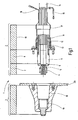
- the Fig. 1 shows a cross section through a connecting device according to the prior art, as offered under the designation CONNEX by the applicant. It is an electrical plug connection device, with a plug element 2 shown in the right half of the picture and a socket element 3 shown in the left half of the picture.
- the plug element 2 has at its end facing the socket element 3 one of a contact ring 4, clamping cone 5 and Pressure piece 6 formed contact system 7 on.
- the outside also has a, an outer cone exhibiting first insulating part 9.
- the housing 10 which in addition to a Flanschglocke 11, a pressure sleeve 12 and a compression spring 13 has.
- the connection line 14, the cable shield 15 and a measuring line 16 are led out of a Anschlußsülle 17, which is formed for example by a shrink tube.
- the female member 3 is formed essentially of the insulating bush 18 as a second insulating part and the female contact 19.
- the female member 3 can be applied to a housing wall 20 and fixed by means of the flange bell 11 of the male member 2 by cross-fastening screws together with the male member 2 on the housing wall.
- an embodiment of the device according to the invention as a socket element corresponding to the device 1 of Fig. 1 described.
- the insulating parts for the plug element can be designed according to the invention.
- the Fig. 2 shows a cross section through a device according to the invention 101 for electrical connection in the form of a socket member in a relation to the Fig. 1 enlarged view.
- the insulating member 118 produced by injection molding of a thermoplastic material is substantially bell-shaped with a substantially approximately equal wall thickness of typically 3 to 5 mm.
- the insulating part has an inner cone 121 with an opening width of, for example, 70 mm, and an opening angle ⁇ , which is adapted to the coefficients of friction of the materials in order to avoid self-clamping and, for example, about 3 °.
- the inner cone 121 of the insulating member 118 is flush with the cone 122 of the contact part 119 end formed first control element 123 to the cone 122 is followed at substantially right angles to the longitudinal axis 127 an annular shoulder surface 124 which by means of an insertion bevel 125 for the contact system of the associated Plug element merges into a substantially cylindrical and in particular circular cylindrical contact surface 126 with a clear width of typically about 40 mm.
- the device 101 is designed, for example, for nominal voltages up to 36 kV.
- the contact part 119 at its opposite end to a substantially cylindrical and in particular circular cylindrical connecting pin 128, which is preferably integrally formed and centrally has a threaded bore 129 for attachment, for example, a current continuing busbar.
- the end face of the connecting pin 128 is circularly offset, so that there is an annular contact surface 130 and consequently a geometrically defined contact surface.
- the dimensions are designed for a rated current of 800 amps.
- the diameter of the connecting pin 128 is about 30 mm
- the width of the annular contact surface about 4 mm
- the threaded hole 129 is designed as M12 threaded hole.
- the contact member 119 also integrally forms a circumferential latching ridge 131, to which a jointly formed by the contact member 119 and the insulating member 118 annular chamber or annular groove for a sealant 132 connects.
- the transition from the substantially perpendicular to the longitudinal axis 127 extending second shoulder surface 133 to the substantially cylindrical outer surface 134 of the main portion of the contact portion 119 is formed by an integrally formed axially projecting toward the contact surface 130 second control member 135 in the form of an annular bead.
- the insulating part 118 has, at its end associated with the connecting pin 128, subsequently to a substantially cylindrical or a small wedge angle of less than 1 ° having portion 136 on the inside conically widening annular lip 137.
- This sealing means 132 ensures a gas-tightness of the transition between the insulating part 118 of the overmolded thermoplastic material and the metallic contact part 119, which is made of aluminum, for example.
- the contact part 119 is preferably formed rotationally symmetrical with respect to the longitudinal axis 127.
- the insulating part 118 integrally forms an annular mounting flange 138.
- six cap sleeves 139 are integrally formed on the flange 138 of the insulating member 118.
- each of these cap sleeves 139 is preferably a metallic threaded bushing 142 (see Fig. 5 ), for the purpose of fixing the device 101 to a housing wall, optionally also with mechanical connection to the associated plug element.
- the Fig. 3 shows a cross section through the contact part 119 of Fig. 2 , In the area of the contact surface 130 and the cylindrical outer surface 140, which is substantially, in particular with the exception of the annular detent web 131, the connecting pin 128 is provided with a coating which reduces the contact resistance. This can for example be given by a silver layer with a minimum layer thickness of 3 ⁇ m, as in Fig. 3 indicated by dash-dotted lines.
- the contact part 119 has a surface structure, for example a knurling or a groove formed parallel to the longitudinal axis 127.
- the cylindrical bore 126 is preferably also full surface including the bottom surface 141 and also provided in the region of the cone 122 of the first control element 123 also with a silver layer, for example in a thickness of about 5 microns.
- the Fig. 4 shows an enlarged section from the region of the transition from the insulating member 118 to the contact member 119 in the region of the sealant 132.
- the contact member 119 forms on two sides and the insulating member 118 on one side an annular groove-shaped chamber for the sealant 132, through which a gas-tight connection is ensured.
- pending protective gas for example, sulfur hexafluoride (SF6), do not get into the generally open to the atmosphere region of the cylindrical bore 126.
- the annular bead-shaped second control element 135 effectively controls the optionally filled with air region of the chamber for the sealant 132.
- the conically widening annular lip 137 facilitates insertion of the sealing means 132. If the pending in the region of the connecting pin 128 gas from the environment is under an overpressure, the sealing means 132 is thereby further held in sealing engagement with the contact member 119 and the insulating member 118.
- the Fig. 5 shows a perspective view of the device 101 of the invention Fig. 2 ,
- a plug element can be inserted and the electrical connection can be continued by means of the connecting pin 121.
- a metallic threaded insert 142 is injected in each of the circumferentially arranged with an angular distance of 60 ° cap sleeves 139.
- the flange 138 forms at the end face a continuous and the cap sleeves interconnecting lowering 143. This essentially serves to ensure a planned installation of the cap sockets 139 or the associated threaded inserts 142, for example, on an associated housing wall.
- a substantially hexagonal web 145 of the recess 143 Radially on the outside and separated by a substantially hexagonal web 145 of the recess 143 extends a substantially also hexagonal groove 144 which is externally bounded by a likewise substantially hexagonal lip 146 and serves to receive a separate sealant.
- the lip 146 is axially set back relative to the web 145, in order to ensure a sealing contact with the web 145 and / or inserted into the groove 144 sealant.
Abstract
Description
Die Erfindung betrifft eine Vorrichtung zum elektrischen Verbinden mit einer Energieversorgungsleitung für Mittel- oder Hochspannung gemäß dem Oberbegriff des Anspruchs 1 sowie ein Verfahren zur Herstellung eines Isolierteils einer solchen Vorrichtung.The invention relates to a device for electrical connection to a power supply line for medium or high voltage according to the preamble of claim 1 and a method for producing an insulating part of such a device.
Bei den bekannten gattungsgemäßen Vorrichtungen, wie sie beispielsweise von der Anmelderin unter dem Kennzeichen CONNEX für Nennspannungen zwischen 1 kV und 150 kV angeboten werden, sind die Isolierteile zwecks Bereitstellung der erforderlichen Teilentladungsfreiheit und der geforderten mechanischen Eigenschaften aus einem qualitativ hochwertigen Gießharz hergestellt. Insbesondere bei höheren Spannungsebenen ist neben der Teilentladungsfreiheit des Isolierteils auch eine Feldsteuerung erforderlich. Zu diesem Zweck werden in die Gießform vom eigentlichen Kontaktteil separate Feldsteuerelemente eingesetzt und anschließend umgossen. Um den geforderten hohen Qualitätsstandard zu gewährleisten ist ein hoher Zeit- und damit Kostenaufwand erforderlich.In the known generic devices, as offered for example by the applicant under the mark CONNEX for rated voltages between 1 kV and 150 kV, the insulating parts in order to provide the required Teilentladungsfreiheit and the required mechanical properties are made of a high quality casting resin. In particular, at higher voltage levels in addition to the partial discharge freedom of the insulating part and a field control is required. For this purpose, separate field control elements are inserted into the casting mold from the actual contact part and then cast around. In order to ensure the required high quality standard, a high time and thus cost is required.
Aus der
Aus der
Der Erfindung liegt daher die Aufgabe zugrunde, eine Verbindungsvorrichtung sowie ein Verfahren zur Herstellung des Isolierteils bereitzustellen, welche die Nachteile des Standes der Technik überwinden. Insbesondere soll die Vorrichtung ausgezeichnete mechanische und elektrische Eigenschaften aufweisen und die zugehörigen Isolierteile sollen kostengünstig und in hoher Qualität herstellbar sein.The invention is therefore based on the object to provide a connecting device and a method for producing the insulating part, which overcome the disadvantages of the prior art. In particular, the device should have excellent mechanical and electrical properties and the associated insulating parts should be inexpensive and can be produced in high quality.
Diese Aufgabe ist durch die im Anspruch 1 bestimmte Vorrichtung sowie das im nebengeordneten Anspruch bestimmte Verfahren gelöst. Besondere Ausführungsarten der Erfindung sind in den Unteransprüchen bestimmt.This object is achieved by the device defined in claim 1 and the method defined in the independent claim. Particular embodiments of the invention are defined in the subclaims.
Die Aufgabe ist bei einer Vorrichtung zum elektrischen Verbinden mit einer Energieversorgungsleitung für Mittel- oder Hochspannung, wobei die Vorrichtung ein Isolierteil und ein elektrisch leitfähiges Kontaktteil aufweist, dadurch gelöst, daß das Isolierteil aus einem thermoplastischen Kunststoff besteht, daß das Isolierteil durch Spritzformen hergestellt ist, und daß beim Spritzformen das Kontaktteil in die Spritzform eingelegt ist und unter Belassen von mindestens einer Zugangsöffnung von dem thermoplastischen Kunststoff umspritzt ist.The object is in a device for electrical connection to a power supply line for medium or high voltage, wherein the device comprises an insulating part and an electrically conductive contact part, achieved in that the insulating part is made of a thermoplastic material, that the insulating part is made by injection molding, and that during injection molding, the contact part is inserted into the injection mold and is encapsulated while leaving at least one access opening of the thermoplastic material.
Vorzugsweise wird für das Spritzformen ein Spritzgießen verwendet, es mag aber auch Anwendungen geben, in denen beispielsweise ein Spritzpressen anwendbar ist. Durch das Einlegen des elektrisch leitfähigen Kontaktteils in die Spritzform und anschließendes Umspritzen ist gegenüber der separaten Herstellung des Isolierteils mit anschließendem Zusammenführen mit dem Kontaktteil der Vorteil verbunden, daß sich bereits beim Spritzformen ein inniger und für viele Anwendungen bereits ausreichend dichter Anlagekontakt zwischen Kontaktteil und Isolierteil ergibt.Preferably, injection molding is used for injection molding, but it may also be applications in which, for example, a transfer molding is applicable. By inserting the electrically conductive contact part in the injection mold and subsequent encapsulation is compared to the separate production of the insulating part with subsequent merging with the contact part has the advantage that already during injection molding an intimate and for many applications already sufficiently dense contact between the contact part and insulating results ,
Wenn darüber hinaus beispielsweise für die Verwendung der Verbindungsvorrichtung in schutzgasbefüllten Schaltanlagen eine Gasdichtheit zwischen Isolierteil und Kontaktteil gefordert ist, kann in einer besonderen Ausführungsart der Erfindung an mindestens einer Stelle des Übergangs vom Kontaktteil zum Isolierteil ein Dichtmittel angeordnet sein. Dieses Dichtmittel kann grundsätzlich auch einstückig von dem Isolierteil ausgebildet sein, beispielsweise in Form einer entsprechend ausgestalteten Dichtlippe, die durch einen gegebenenfalls vorhandenen Druckunterschied in dichtender Anlage haltbar ist. Vorzugsweise kommt jedoch ein separates Dichtmittel zur Anwendung, das insbesondere in eine von dem Isolierteil und dem Kontaktteil gebildeten Kammer nach dem Spritzformen einsteckbar ist. Hierzu kann das Isolierteil und/oder das Kontaktteil ein Rastmittel, beispielsweise eine Rastnase oder Rastlippe ausbilden, durch die ein korrekter Sitzt des Dichtmittels gewährleistet ist.In addition, if, for example, for the use of the connecting device in Schutzgasbefüllten switchgear gas tightness between the insulating part and contact part is required, in a particular embodiment of the invention at least one point of the transition from the contact part to the insulating part, a sealing means may be arranged. In principle, this sealing means can also be formed in one piece from the insulating part, for example in the form of a correspondingly designed sealing lip which can be held in sealing engagement by an optionally existing pressure difference. Preferably, however, a separate sealing means is used, which can be inserted in particular into a chamber formed by the insulating part and the contact part after the injection molding. For this purpose, the insulating part and / or the contact part form a latching means, for example a latching lug or latching lip, by which a correct fit of the sealing means is ensured.
Das Kontaktteil ist vorzugsweise aus Aluminium hergestellt, wobei die Oberfläche an den geeigneten Stellen zur Herabsetzung des Kontaktwiderstandes mit einer Kontaktschicht versehen sein kann, beispielsweise versilbert sein kann. An der zur Weiterführung der elektrischen Verbindung vorgesehenen Stelle kann das Kontaktteil vorzugsweise einstückig einen oder mehrere linien- oder punktförmige Kontakte ausbilden zwecks Bereitstellen von definierten Kontaktstellen und Kontaktflächen.The contact part is preferably made of aluminum, wherein the surface may be provided at the appropriate locations to reduce the contact resistance with a contact layer, for example, may be silvered. At the point provided for the continuation of the electrical connection, the contact part can preferably form in one piece one or more linear or punctiform contacts for the purpose of providing defined contact points and contact surfaces.
An seiner dem Isolierteil zugeordneten Anlagefläche kann das Kontaktteil mindestens abschnittsweise eine Oberflächenstruktur aufweisen. Dadurch ist die Festigkeit der Verbindung zwischen Kontaktteil und Isolierteil weiter erhöht und insbesondere die Verdrehsicherheit des Kontaktteils gegenüber dem beispielsweise an einer Gehäusewand fest montierten Isolierteil.At its contact surface assigned to the insulating part, the contact part may have a surface structure at least in sections. As a result, the strength of the connection between the contact part and insulating part is further increases and in particular the security against rotation of the contact part relative to the example fixed to a housing wall mounted insulating.
In einer besonderen Ausführungsart der Erfindung bildet das Kontaktteil einstückig Steuerelemente aus zum Absteuern des elektrischen Feldes an den diesbezüglich kritischen Stellen. Durch die einstückige Ausbildung ist gewährleistet, daß auch bei den beim Spritzformen angewendeten hohen Prozeßdrücken die Verbindung zwischen Kontaktteil und Steuerelement und die Position und/oder Ausrichtung des Steuerelements erhalten bleibt. Erforderlichenfalls können über die einstückig ausgebildeten Steuerelemente hinaus auch noch weitere Steuerelemente vorgesehen sein, die auch in herkömmlicher Weise in die Spritzform eingelegt werden können.In a particular embodiment of the invention, the contact part integrally forms controls for Absteuern of the electric field at the critical points in this regard. The one-piece design ensures that the connection between the contact part and control and the position and / or orientation of the control is maintained even when applied during injection molding high process pressures. If necessary, in addition to the integrally formed controls also further controls may be provided, which can be inserted in a conventional manner in the injection mold.
In einer besonderen Ausführungsart der Erfindung handelt es sich bei der Verbindungsvorrichtung um eine Steckvorrichtung. Das Isolierteil bildet dabei einen Steckerkörper oder einen Buchsenkörper. In beiden Fällen kann das Isolierteil einen Konus aufweisen, beispielsweise einen Innenoder Außenkonus, der mit dem entsprechenden Gegenelement der Verbindungsvorrichtung zusammenwirkt, der seinerseits einen Außen- bzw. Innenkonus aufweist.In a particular embodiment of the invention, the connecting device is a plug-in device. The insulating part forms a plug body or a socket body. In both cases, the insulating part may have a cone, for example an inner or outer cone, which cooperates with the corresponding counter element of the connecting device, which in turn has an outer or inner cone.
Die Erfindung betrifft auch ein Verfahren zum Herstellen eines Isolierteils einer erfindungsgemäßen Vorrichtung. Gemäß dem erfindungsgemäßen Verfahren wird zunächst ein elektrisch leitfähiges Kontaktteil in eine Spritzform eingelegt und anschließend ein thermoplastischer Kunststoff unter Bildung des Isolierteils um das Kontaktteil herum angeformt unter Belassen mindestens einer Zugangsöffnung zu dem Kontaktteil.The invention also relates to a method for producing an insulating part of a device according to the invention. According to the method of the invention, first an electrically conductive contact part is inserted into an injection mold and then a thermoplastic material is formed to form the insulating part around the contact part while leaving at least one access opening to the contact part.
Der thermoplastische Kunststoff basiert oder besteht vorzugsweise aus einem teilkristallinen, partiell aromatischen Polyamid. Dadurch sind günstige mechanische und elektrische Eigenschaften der hergestellten Isolierteile gewährleistet. In einer besonderen Ausführungsart ist der thermoplastische Kunststoff darüber hinaus glasfaserverstärkt oder mineralverstärkt. Dadurch lassen sich Isolierteile herstellen, die kurzzeitig Temperaturen bis zu 300° ausgesetzt werden können.The thermoplastic material is based or preferably consists of a partially crystalline, partially aromatic polyamide. As a result, favorable mechanical and electrical properties of the insulating parts produced are ensured. In a particular embodiment of the thermoplastic material is also glass fiber reinforced or mineral-reinforced. This makes it possible to produce insulating parts that can be exposed to temperatures of up to 300 ° C for a short time.
In einer besonderen Ausführungsart der Erfindung erfolgt mindestens ein Teil des Spritzformvorgangs unter gegenüber Atmosphäre reduziertem Druck, Vakuum oder in einer mindestens teilweise Inertgas-Atmosphäre. Beispielsweise kann Schwefelhexafluorid (SF6) als Inertgas beim Spritzgießen verwendet werden.In a particular embodiment of the invention, at least part of the injection molding operation takes place under reduced pressure, reduced pressure or in an at least partially inert gas atmosphere. For example, sulfur hexafluoride (SF6) can be used as an inert gas in injection molding.
Vorzugsweise wird die Masse des thermoplastischen Kunststoffs vor dem Spritzformen auf eine Temperatur von mehr als 180° Celsius, insbesondere mehr als 250° Celsius, und vorzugsweise zwischen 300° und 350° Celsius gebracht. Anschließend wird die so erhitzte Kunststoffmasse in die Form eingebracht, die eine Temperatur von mehr als 60° Celsius, insbesondere mehr als 90° Celsius, und vorzugsweise zwischen 100° und 160° Celsius aufweist.Preferably, the mass of the thermoplastic material is brought to a temperature of more than 180 ° Celsius, in particular more than 250 ° Celsius, and preferably between 300 ° and 350 ° Celsius before injection molding. Subsequently, the thus heated plastic mass is introduced into the mold, which has a temperature of more than 60 ° Celsius, in particular more than 90 ° Celsius, and preferably between 100 ° and 160 ° Celsius.
In einer besonderen Ausführungsart werden der Kunststoffmasse keine Farbstoffe zugesetzt. Vielmehr wird beispielsweise die gelblich-graue Eigenfarbe der Kunststoffmasse unverändert gelassen, um anhand auftretender Verfärbungen oder auch dem Ausbleiben solcher Verfärbungen eine optimale Prozeßführung ablesen zu können. Außerdem sind durch die nicht-eingefärbte Kunststoffmasse Lunker und Risse im Isolierteil erkennbar.In a particular embodiment, the dyes are not added to the plastic composition. Rather, for example, the yellowish-gray intrinsic color of the plastic composition is left unchanged to be able to read on the basis of discoloration occurring or the absence of such discoloration optimal process control. In addition, voids and cracks in the insulating part can be recognized by the non-colored plastic compound.
Weitere Vorteile, Merkmale und Einzelheiten der Erfindung ergeben sich aus den Unteransprüchen und der nachfolgenden Beschreibung, in der unter Bezugnahme auf die Zeichnungen ein Ausführungsbeispiel im Einzelnen beschrieben ist. Dabei können die in den Ansprüchen und in der Beschreibung erwähnten Merkmale jeweils einzeln für sich oder in beliebiger Kombination erfindungswesentlich sein.
- Fig. 1
- zeigt einen Querschnitt durch eine Verbindungseinrichtung nach dem Stand der Technik,
- Fig. 2
- zeigt einen Querschnitt durch eine erfindungsgemäße Vorrichtung in einer gegenüber der
Fig. 1 vergrößerten Darstellung, - Fig. 3
- zeigt einen Querschnitt durch das Kontaktteil der Vorrichtung der
Fig. 2 , - Fig. 4
- zeigt einen gegenüber der Darstellung in der
Fig. 2 vergrößerten Ausschnitt aus dem Bereich des Übergangs von dem Isolierteil zu dem Kontaktteil im Bereich des Dichtmittels, und - Fig. 5
- zeigt eine perspektivische Ansicht der erfindungsgemäßen Vorrichtung der
Fig. 2 .
- Fig. 1
- shows a cross section through a connecting device according to the prior art,
- Fig. 2
- shows a cross section through a device according to the invention in a relation to the
Fig. 1 enlarged view, - Fig. 3
- shows a cross section through the contact part of the device of
Fig. 2 . - Fig. 4
- shows a relation to the representation in the
Fig. 2 enlarged section of the region of the transition from the insulating part to the contact part in the region of the sealant, and - Fig. 5
- shows a perspective view of the device according to the invention the
Fig. 2 ,
Die
Das Steckerelement 2 weist an seinem dem Buchsenelement 3 zugewandten Ende ein aus einem Kontaktring 4, Spannkonus 5 und Druckstück 6 gebildetes Kontaktsystem 7 auf. Daran schließt sich ein Isolier- und Absteuerteil 8 an, das außenseitig ebenfalls ein, einen Außenkonus aufweisendes erstes Isolierteil 9 aufweist. An seinem von dem Kontaktsystem 7 beabstandeten Ende schließt sich an das Isolier- und Absteuerteil 8 das Gehäuse 10 an, das neben einer Flanschglocke 11, eine Druckhülse 12 und eine Druckfeder 13 aufweist. Endseitig sind aus dem Gehäuse 10 die Anschlußleitung 14, der Kabelschirm 15 und eine Meßleitung 16 aus einer Anschlußtülle 17 herausgeführt, die beispielsweise durch einen Schrumpfschlauch gebildet ist.The plug element 2 has at its end facing the
Das Buchsenelement 3 ist im wesentlichen aus dem als Isolierbuchse 18 ausgeführten zweiten Isolierteil und der Kontaktbuchse 19 gebildet. Das Buchsenelement 3 ist an eine Gehäusewand 20 anlegbar und mittels der die Flanschglocke 11 des Steckerelements 2 durchgreifenden Befestigungsschrauben zusammen mit dem Steckerelement 2 an der Gehäusewand festlegbar.The
In der nachfolgenden Figurenbeschreibung wird ein Ausführungsbeispiel der erfindungsgemäßen Vorrichtung als Buchsenelement entsprechend der Einrichtung 1 der
Die
In Richtung des zugehörigen, in der
Der Innenkonus 121 des Isolierteils 118 fluchtet bündig mit dem Konus 122 des vom Kontaktteil 119 endseitig ausgebildeten ersten Steuerelements 123. An den Konus 122 schließt sich im wesentlichen rechtwinklig zur Längsachse 127 eine ringförmige Absatzfläche 124 an, die mittels einer Einführschräge 125 für das Kontaktsystem des zugehörigen Steckerelements übergeht in eine im wesentlichen zylindrische und insbesondere kreiszylindrische Kontaktfläche 126 mit einer lichten Weite von typisch etwa 40 mm. Die Vorrichtung 101 ist beispielsweise für Nennspannungen bis 36 kV ausgelegt.Towards the associated, in the
The
Unter Weiterführung der elektrischen Verbindung weist das Kontaktteil 119 an seinem gegenüberliegenden Ende einen im wesentlichen zylindrischen und insbesondere kreiszylindrischen Anschlußzapfen 128 auf, der vorzugsweise einstückig ausgebildet ist und zentrisch eine Gewindebohrung 129 zur Befestigung beispielsweise einer den Strom weiterführenden Sammelschiene aufweist. Neben der übliche Einführschräge für die Gewindebohrung 129 ist die Stirnfläche des Anschlußzapfens 128 kreisförmig abgesetzt, so daß sich eine kreisringförmige Kontaktfläche 130 und mithin eine geometrisch definierte Kontaktfläche ergibt. Im dargestellten Ausführungsbeispiel sind die Abmessungen für einen Nennstrom von 800 Ampere ausgelegt. Hierzu beträgt der Durchmesser des Anschlußzapfens 128 etwa 30 mm, die Breite der ringförmigen Kontaktfläche etwa 4 mm und die Gewindebohrung 129 ist als M12-Gewindebohrung ausgelegt.Continuing the electrical connection, the
Wie in der nachfolgenden
Das Isolierteil 118 weist an seinem dem Anschlußzapfen 128 zugeordneten Ende anschließend an einen im wesentlichen zylindrischen oder einen geringen Keilwinkel von weniger als 1° aufweisenden Abschnitt 136 eine sich auf der Innenseite konisch aufweitende Ringlippe 137 auf. Dadurch ist das Einsetzen bzw. Einklipsen des Dichtmittels 132 vereinfacht, für das im Ausführungsbeispiel ein handelsüblicher Dichtring verwendet werden kann. Dieses Dichtmittel 132 gewährleistet eine Gasdichtheit des Übergangs zwischen dem Isolierteil 118 aus dem umspritzten thermoplastischen Kunststoff und dem metallischen Kontaktteil 119, das beispielsweise aus Aluminium hergestellt ist. Mit Ausnahme der Gewindebohrung 129 ist das Kontaktteil 119 vorzugsweise rotationssymmetrisch in Bezug auf die Längsachse 127 ausgebildet.The insulating
An seinem, von dem Kontaktteil 119 wegweisenden Ende bildet das Isolierteil 118 einstückig einen ringförmigen Befestigungsflansch 138 aus.
In Umfangsrichtung sind an dem Flansch 138 äquidistant beispielsweise sechs Hutbuchsen 139 einstückig von dem Isolierteil 118 ausgebildet.At its end facing away from the
In the circumferential direction equidistantly, for example, six
In jede dieser Hutbuchsen 139 ist vorzugsweise eine metallische Gewindebuchse 142 (siehe
Die
Im Bereich der Kontaktfläche 130 und der im wesentlichen, insbesondere mit Ausnahme des ringförmigen Raststeges 131, zylindrischen Mantelfläche 140 ist der Anschlußzapfen 128 mit einer den Kontaktwiderstand herabsetzenden Beschichtung versehen. Dies kann beispielsweise durch eine Silberschicht mit einer Mindestschichtdicke von 3 µm gegeben sein, wie dies in
In the area of the
An der im wesentlichen zylindrischen Mantelfläche 134 weist das Kontaktteil 119 eine Oberflächenstruktur auf, beispielsweise eine Rändelung oder eine parallel zur Längsachse 127 ausgebildete Rillung.
Die zylindrische Bohrung 126 ist vorzugsweise vollflächig einschließlich der Bodenfläche 141 und bis in den Bereich des Konus 122 des ersten Steuerelements 123 ebenfalls mit einer Silberschicht versehen, beispielsweise in einer Dicke von etwa 5 µm.On the substantially cylindrical
The
Die
Das ringwulstförmige zweite Steuerelement 135 steuert den gegebenenfalls mit Luft gefüllten Bereich der Kammer für das Dichtmittel 132 wirksam ab. Die sich konisch aufweitende Ringlippe 137 erleichtert das Einsetzen des Dichtmittels 132. Sofern das im Bereich des Anschlußzapfens 128 anstehende Gas gegenüber der Umgebung unter einem Überdruck steht, wird das Dichtmittel 132 hierdurch noch weiter in dichtende Anlage an dem Kontaktteil 119 und dem Isolierteil 118 gehalten.The annular bead-shaped
Die
Radial außenseitig und durch einem im wesentlichen sechseckigen Steg 145 von der Absenkung 143 abgetrennt verläuft eine im wesentlichen ebenfalls sechseckförmige Nut 144, die außenseitig von einer ebenfalls im wesentlichen sechseckförmigen Lippe 146 begrenzt ist und zur Aufnahme eines separaten Dichtmittels dient. Hierzu ist die Lippe 146 axial gegenüber dem Steg 145 etwa zurückversetzt, um eine dichtende Anlage durch den Steg 145 und/oder das in die Nut 144 eingelegte Dichtmittel zu gewährleisten.Radially on the outside and separated by a substantially
Claims (14)
- Device (101) for electrical connection with a power supply line for medium or high voltage, wherein the device (101) has an insulating part (118) and an electrically conductive contact part (119), characterised in that the insulating part (118) is made of a thermoplastic plastic, in that the insulating part (118) is manufactured by injection moulding, and in that, in the injection moulding, the contact part (119) is placed in the injection mould and overmoulded with the thermoplastic plastic, at least one access opening being left free.
- Device (101) according to claim 1, characterised in that at at least one point of the transition from the contact part (119) to the insulating part (118) there is arranged a sealing means (132) for producing a gas-tight connection between the insulating part (118) and the contact part (119).
- Device (101) according to claim 2, characterised in that, after the injection moulding, the sealing means (132) can be inserted into a chamber formed by the insulating part (118) and the contact part (119).
- Device (101) according to any one of claims 1 to 3, characterised in that the contact part (119) forms integral control elements (123, 135) for controlling the electrical field.
- Device (101) according to any one of claims 1 to 4, characterised in that the contact part (119) forms an integral linear contact for continuing the electrical connection.
- Device (101) according to any one of claims 1 to 5, characterised in that the contact part (119) has a surface texture on at least part of its contact surface associated with the insulating part (118).
- Device (101) according to any one of claims 1 to 6, characterised in that the thermoplastic plastic of the insulating part (118) comprises a polyamide, in particular a partially aromatic polyamide.
- Device according to claim 7, characterised in that the thermoplastic plastic is glass- fibre-reinforced or mineral-reinforced.
- Device (101) according to any one of claims 1 to 8, characterised in that it is a plug-type device and the insulating part (118) forms a plug body or a socket body.
- Device (101) according to any one of claims 1 to 9, characterised in that the insulating part (118) has an inner or outer cone.
- Process for the manufacture of an insulating part (118) of a device (101) for electrical connection with a power supply line for medium or high voltage, wherein an electrically conductive contact part (119) is placed an injection mould and then a thermoplastic plastic is injected moulded around the contact part (119) to form the insulating part (118), at least one access opening to the contact part (119) being left free.
- Process according to claim 11, characterised in that the injection moulding operation is carried out at least partially under vacuum or in an inert gas atmosphere.
- Process according to claim 11 or 12, characterised in that, prior to the injection moulding, the plastics material is brought to a temperature of more than 180°C, in particular more than 250°C and preferably from 300 to 350°C, before the plastics material has been introduced into the mould, which has a temperature of more than 60°C, in particular more than 90°C and preferably from 100 to 160°C.
- Process according to any one of claims 11 to 13, characterised in that the thermoplastic plastic is processed in its inherent colour, in particular without additional dyes.
Applications Claiming Priority (2)
| Application Number | Priority Date | Filing Date | Title |
|---|---|---|---|
| DE10332118A DE10332118A1 (en) | 2003-07-09 | 2003-07-09 | Device for electrical connection to a power supply line for medium or high voltage and method for producing an insulating part of such a device |
| DE10332118 | 2003-07-09 |
Publications (3)
| Publication Number | Publication Date |
|---|---|
| EP1496576A2 EP1496576A2 (en) | 2005-01-12 |
| EP1496576A3 EP1496576A3 (en) | 2008-03-26 |
| EP1496576B1 true EP1496576B1 (en) | 2012-04-04 |
Family
ID=33441765
Family Applications (1)
| Application Number | Title | Priority Date | Filing Date |
|---|---|---|---|
| EP04016065A Revoked EP1496576B1 (en) | 2003-07-09 | 2004-07-08 | Device for electrical connection with a power supply line for medium or high voltage and process for manufacturing an insulating portion of such a device |
Country Status (4)
| Country | Link |
|---|---|
| EP (1) | EP1496576B1 (en) |
| AT (1) | ATE552630T1 (en) |
| DE (1) | DE10332118A1 (en) |
| ES (1) | ES2381106T3 (en) |
Families Citing this family (4)
| Publication number | Priority date | Publication date | Assignee | Title |
|---|---|---|---|---|
| EP1845596A1 (en) | 2006-04-13 | 2007-10-17 | ABB Research Ltd | An electric connection device and a method of producing such a device |
| EP2276041B1 (en) | 2009-07-15 | 2013-09-25 | ABB Research Ltd. | A device for electric connection and an electric installation |
| EP2276040B1 (en) | 2009-07-15 | 2017-03-01 | ABB Research LTD | A device for electric connection, a method for producing such a device, and an electric installation |
| CN105490076B (en) * | 2016-01-04 | 2018-03-16 | 北京航天试验技术研究所 | Suitable for the capacitance type sensor lead-in wire sealing plug under vacuum or hyperbaric environment |
Family Cites Families (11)
| Publication number | Priority date | Publication date | Assignee | Title |
|---|---|---|---|---|
| DE2944120C2 (en) | 1979-10-30 | 1983-02-10 | Siemens AG, 1000 Berlin und 8000 München | Elastic control element for sets of electrical cables and a method for producing such a control element |
| DE3247673C2 (en) * | 1982-12-23 | 1986-02-13 | Karl Pfisterer Elektrotechnische Spezialartikel Gmbh & Co Kg, 7000 Stuttgart | Socket with a field control element |
| DE3611462A1 (en) * | 1986-04-05 | 1987-10-15 | Pfisterer Elektrotech Karl | Connecting fitting for conductors of a medium-voltage or high-voltage network |
| DE4001191A1 (en) * | 1990-01-17 | 1991-07-18 | Concordia Sprecher Energie | Heavy duty plug and socket - has inner and outer main conical coupling with additional coupling at right angles |
| JPH0438113A (en) | 1990-05-31 | 1992-02-07 | Furukawa Electric Co Ltd:The | Manufacture of epoxy unit buried with electrode |
| DE4135391C1 (en) * | 1991-10-26 | 1992-12-10 | Karl Pfisterer Elektrotechnische Spezialartikel Gmbh & Co Kg, 7000 Stuttgart, De | Cable connector for medium high voltage and high current - has socket with cup-shaped contact element, and cylindrical insulating housing covering inserted cable |
| DE4224672C1 (en) * | 1992-07-25 | 1993-09-09 | Karl Pfisterer Elektrotechnische Spezialartikel Gmbh & Co Kg, 7000 Stuttgart, De | |
| DE19717302A1 (en) * | 1997-04-24 | 1998-10-29 | Battenfeld Gmbh | Pressure injection moulding process especially suitable for high quality and micro-engineered parts |
| FR2783082B1 (en) * | 1998-09-09 | 2000-11-24 | Siemens Automotive Sa | OVER-MOLDED ELECTRIC CABLE AND METHOD FOR PRODUCING SUCH A CABLE |
| DE10006211C2 (en) * | 2000-02-11 | 2003-11-27 | Robert Virant | Mold-molded, electrical and / or electronic component and method of manufacture |
| US6830475B2 (en) * | 2002-05-16 | 2004-12-14 | Homac Mfg. Company | Electrical connector with visual seating indicator and associated methods |
-
2003
- 2003-07-09 DE DE10332118A patent/DE10332118A1/en not_active Withdrawn
-
2004
- 2004-07-08 EP EP04016065A patent/EP1496576B1/en not_active Revoked
- 2004-07-08 ES ES04016065T patent/ES2381106T3/en active Active
- 2004-07-08 AT AT04016065T patent/ATE552630T1/en active
Also Published As
| Publication number | Publication date |
|---|---|
| ATE552630T1 (en) | 2012-04-15 |
| EP1496576A2 (en) | 2005-01-12 |
| DE10332118A1 (en) | 2005-02-10 |
| ES2381106T3 (en) | 2012-05-23 |
| EP1496576A3 (en) | 2008-03-26 |
Similar Documents
| Publication | Publication Date | Title |
|---|---|---|
| EP0889774B1 (en) | Plastic resistor and process for producing it | |
| DE60314867T2 (en) | ELECTRICAL CONNECTOR CONSISTING OF ELASTOMER MATERIALS AND ASSOCIATED METHODS | |
| DE19733181C2 (en) | Cable connector and method of making a cable connector | |
| EP3821260B1 (en) | Voltage division device having a rod-like structure | |
| EP1496576B1 (en) | Device for electrical connection with a power supply line for medium or high voltage and process for manufacturing an insulating portion of such a device | |
| EP1876682B1 (en) | Cable plug of a plug-type connection device for medium-voltage and high-voltage technics | |
| WO1996011408A1 (en) | Fitting in the form of a lead-through or a socket for cable plugs | |
| DE4225267C2 (en) | Sealing device for an electronic switching device | |
| DE4423985C2 (en) | Method for producing a moisture-proof connection of an electrical line to a thermistor of a temperature sensor | |
| EP0692153B1 (en) | Armature for conductors of high-voltage power supply systems and process for producing it | |
| EP3340392A1 (en) | Assembly for connection of electrical lines | |
| DE202012004919U1 (en) | Sealing element for an electrical connector and electrical connector | |
| EP3821259B1 (en) | Voltage-dividing device having a siloxane dielectric | |
| EP2448369B1 (en) | Electrical connection device for an electric heating element of a hot runner nozzle | |
| EP0893683A1 (en) | Sensor for detecting fluid contamination | |
| EP1487074A1 (en) | Sleeve for high voltage cable and process of manufacturing the same | |
| DE3326386C2 (en) | ||
| EP3358690A1 (en) | Coupling sleeve | |
| DE3538193C2 (en) | ||
| DE3806369A1 (en) | Method for producing a cable plug, and a casting mould or injection mould for carrying out the method | |
| WO2009012898A1 (en) | Vacuum housing and method for producing an insert for a vacuum housing | |
| DE4343203C1 (en) | Medium-voltage or high-voltage fitting | |
| DE102009052353A1 (en) | Contact plug for electrical connection between controller and electrical power supply cable in automobile, has electric safety device with contact section contacting contact end, and another contact section contacting another contact end | |
| DE19607737A1 (en) | Electric capacitor | |
| DE102018116416A1 (en) | coupling sleeve |
Legal Events
| Date | Code | Title | Description |
|---|---|---|---|
| PUAI | Public reference made under article 153(3) epc to a published international application that has entered the european phase |
Free format text: ORIGINAL CODE: 0009012 |
|
| AK | Designated contracting states |
Kind code of ref document: A2 Designated state(s): AT BE BG CH CY CZ DE DK EE ES FI FR GB GR HU IE IT LI LU MC NL PL PT RO SE SI SK TR |
|
| AX | Request for extension of the european patent |
Extension state: AL HR LT LV MK |
|
| PUAL | Search report despatched |
Free format text: ORIGINAL CODE: 0009013 |
|
| AK | Designated contracting states |
Kind code of ref document: A3 Designated state(s): AT BE BG CH CY CZ DE DK EE ES FI FR GB GR HU IE IT LI LU MC NL PL PT RO SE SI SK TR |
|
| AX | Request for extension of the european patent |
Extension state: AL HR LT LV MK |
|
| 17P | Request for examination filed |
Effective date: 20080417 |
|
| AKX | Designation fees paid |
Designated state(s): AT BE BG CH CY CZ DE DK EE ES FI FR GB GR HU IE IT LI LU MC NL PL PT RO SE SI SK TR |
|
| RAP1 | Party data changed (applicant data changed or rights of an application transferred) |
Owner name: PFISTERER KONTAKTSYSTEME GMBH |
|
| 17Q | First examination report despatched |
Effective date: 20100325 |
|
| GRAP | Despatch of communication of intention to grant a patent |
Free format text: ORIGINAL CODE: EPIDOSNIGR1 |
|
| RTI1 | Title (correction) |
Free format text: DEVICE FOR ELECTRICAL CONNECTION WITH A POWER SUPPLY LINE FOR MEDIUM OR HIGH VOLTAGE AND PROCESS FOR MANUFACTURING AN INSULATING PORTION OF SUCH A DEVICE |
|
| GRAC | Information related to communication of intention to grant a patent modified |
Free format text: ORIGINAL CODE: EPIDOSCIGR1 |
|
| GRAS | Grant fee paid |
Free format text: ORIGINAL CODE: EPIDOSNIGR3 |
|
| GRAA | (expected) grant |
Free format text: ORIGINAL CODE: 0009210 |
|
| AK | Designated contracting states |
Kind code of ref document: B1 Designated state(s): AT BE BG CH CY CZ DE DK EE ES FI FR GB GR HU IE IT LI LU MC NL PL PT RO SE SI SK TR |
|
| REG | Reference to a national code |
Ref country code: GB Ref legal event code: FG4D Free format text: NOT ENGLISH |
|
| REG | Reference to a national code |
Ref country code: CH Ref legal event code: NV Representative=s name: ISLER & PEDRAZZINI AG Ref country code: CH Ref legal event code: EP |
|
| REG | Reference to a national code |
Ref country code: AT Ref legal event code: REF Ref document number: 552630 Country of ref document: AT Kind code of ref document: T Effective date: 20120415 |
|
| REG | Reference to a national code |
Ref country code: IE Ref legal event code: FG4D Free format text: LANGUAGE OF EP DOCUMENT: GERMAN |
|
| REG | Reference to a national code |
Ref country code: NL Ref legal event code: T3 |
|
| REG | Reference to a national code |
Ref country code: ES Ref legal event code: FG2A Ref document number: 2381106 Country of ref document: ES Kind code of ref document: T3 Effective date: 20120523 |
|
| REG | Reference to a national code |
Ref country code: DE Ref legal event code: R096 Ref document number: 502004013408 Country of ref document: DE Effective date: 20120531 |
|
| PG25 | Lapsed in a contracting state [announced via postgrant information from national office to epo] |
Ref country code: CY Free format text: LAPSE BECAUSE OF FAILURE TO SUBMIT A TRANSLATION OF THE DESCRIPTION OR TO PAY THE FEE WITHIN THE PRESCRIBED TIME-LIMIT Effective date: 20120404 Ref country code: SE Free format text: LAPSE BECAUSE OF FAILURE TO SUBMIT A TRANSLATION OF THE DESCRIPTION OR TO PAY THE FEE WITHIN THE PRESCRIBED TIME-LIMIT Effective date: 20120404 Ref country code: FI Free format text: LAPSE BECAUSE OF FAILURE TO SUBMIT A TRANSLATION OF THE DESCRIPTION OR TO PAY THE FEE WITHIN THE PRESCRIBED TIME-LIMIT Effective date: 20120404 Ref country code: SI Free format text: LAPSE BECAUSE OF FAILURE TO SUBMIT A TRANSLATION OF THE DESCRIPTION OR TO PAY THE FEE WITHIN THE PRESCRIBED TIME-LIMIT Effective date: 20120404 Ref country code: PL Free format text: LAPSE BECAUSE OF FAILURE TO SUBMIT A TRANSLATION OF THE DESCRIPTION OR TO PAY THE FEE WITHIN THE PRESCRIBED TIME-LIMIT Effective date: 20120404 |
|
| PG25 | Lapsed in a contracting state [announced via postgrant information from national office to epo] |
Ref country code: GR Free format text: LAPSE BECAUSE OF FAILURE TO SUBMIT A TRANSLATION OF THE DESCRIPTION OR TO PAY THE FEE WITHIN THE PRESCRIBED TIME-LIMIT Effective date: 20120705 Ref country code: PT Free format text: LAPSE BECAUSE OF FAILURE TO SUBMIT A TRANSLATION OF THE DESCRIPTION OR TO PAY THE FEE WITHIN THE PRESCRIBED TIME-LIMIT Effective date: 20120806 |
|
| PLBI | Opposition filed |
Free format text: ORIGINAL CODE: 0009260 |
|
| BERE | Be: lapsed |
Owner name: PFISTERER KONTAKTSYSTEME G.M.B.H. Effective date: 20120731 |
|
| PG25 | Lapsed in a contracting state [announced via postgrant information from national office to epo] |
Ref country code: SK Free format text: LAPSE BECAUSE OF FAILURE TO SUBMIT A TRANSLATION OF THE DESCRIPTION OR TO PAY THE FEE WITHIN THE PRESCRIBED TIME-LIMIT Effective date: 20120404 Ref country code: CZ Free format text: LAPSE BECAUSE OF FAILURE TO SUBMIT A TRANSLATION OF THE DESCRIPTION OR TO PAY THE FEE WITHIN THE PRESCRIBED TIME-LIMIT Effective date: 20120404 Ref country code: EE Free format text: LAPSE BECAUSE OF FAILURE TO SUBMIT A TRANSLATION OF THE DESCRIPTION OR TO PAY THE FEE WITHIN THE PRESCRIBED TIME-LIMIT Effective date: 20120404 Ref country code: RO Free format text: LAPSE BECAUSE OF FAILURE TO SUBMIT A TRANSLATION OF THE DESCRIPTION OR TO PAY THE FEE WITHIN THE PRESCRIBED TIME-LIMIT Effective date: 20120404 Ref country code: DK Free format text: LAPSE BECAUSE OF FAILURE TO SUBMIT A TRANSLATION OF THE DESCRIPTION OR TO PAY THE FEE WITHIN THE PRESCRIBED TIME-LIMIT Effective date: 20120404 |
|
| 26 | Opposition filed |
Opponent name: ABB AB Effective date: 20121228 |
|
| PLAX | Notice of opposition and request to file observation + time limit sent |
Free format text: ORIGINAL CODE: EPIDOSNOBS2 |
|
| PG25 | Lapsed in a contracting state [announced via postgrant information from national office to epo] |
Ref country code: MC Free format text: LAPSE BECAUSE OF NON-PAYMENT OF DUE FEES Effective date: 20120731 |
|
| GBPC | Gb: european patent ceased through non-payment of renewal fee |
Effective date: 20120708 |
|
| REG | Reference to a national code |
Ref country code: DE Ref legal event code: R026 Ref document number: 502004013408 Country of ref document: DE Effective date: 20121228 |
|
| PLAB | Opposition data, opponent's data or that of the opponent's representative modified |
Free format text: ORIGINAL CODE: 0009299OPPO |
|
| PG25 | Lapsed in a contracting state [announced via postgrant information from national office to epo] |
Ref country code: GB Free format text: LAPSE BECAUSE OF NON-PAYMENT OF DUE FEES Effective date: 20120708 |
|
| REG | Reference to a national code |
Ref country code: IE Ref legal event code: MM4A |
|
| R26 | Opposition filed (corrected) |
Opponent name: ABB AB Effective date: 20121228 |
|
| PLAF | Information modified related to communication of a notice of opposition and request to file observations + time limit |
Free format text: ORIGINAL CODE: EPIDOSCOBS2 |
|
| PG25 | Lapsed in a contracting state [announced via postgrant information from national office to epo] |
Ref country code: BE Free format text: LAPSE BECAUSE OF NON-PAYMENT OF DUE FEES Effective date: 20120731 |
|
| PLBB | Reply of patent proprietor to notice(s) of opposition received |
Free format text: ORIGINAL CODE: EPIDOSNOBS3 |
|
| PG25 | Lapsed in a contracting state [announced via postgrant information from national office to epo] |
Ref country code: BG Free format text: LAPSE BECAUSE OF FAILURE TO SUBMIT A TRANSLATION OF THE DESCRIPTION OR TO PAY THE FEE WITHIN THE PRESCRIBED TIME-LIMIT Effective date: 20120704 Ref country code: IE Free format text: LAPSE BECAUSE OF NON-PAYMENT OF DUE FEES Effective date: 20120708 |
|
| PGFP | Annual fee paid to national office [announced via postgrant information from national office to epo] |
Ref country code: FR Payment date: 20130628 Year of fee payment: 10 |
|
| PGFP | Annual fee paid to national office [announced via postgrant information from national office to epo] |
Ref country code: AT Payment date: 20130722 Year of fee payment: 10 Ref country code: ES Payment date: 20130702 Year of fee payment: 10 Ref country code: DE Payment date: 20130521 Year of fee payment: 10 Ref country code: NL Payment date: 20130724 Year of fee payment: 10 Ref country code: CH Payment date: 20130711 Year of fee payment: 10 |
|
| PGFP | Annual fee paid to national office [announced via postgrant information from national office to epo] |
Ref country code: IT Payment date: 20130704 Year of fee payment: 10 |
|
| PG25 | Lapsed in a contracting state [announced via postgrant information from national office to epo] |
Ref country code: TR Free format text: LAPSE BECAUSE OF FAILURE TO SUBMIT A TRANSLATION OF THE DESCRIPTION OR TO PAY THE FEE WITHIN THE PRESCRIBED TIME-LIMIT Effective date: 20120404 |
|
| PG25 | Lapsed in a contracting state [announced via postgrant information from national office to epo] |
Ref country code: LU Free format text: LAPSE BECAUSE OF NON-PAYMENT OF DUE FEES Effective date: 20120708 |
|
| PG25 | Lapsed in a contracting state [announced via postgrant information from national office to epo] |
Ref country code: HU Free format text: LAPSE BECAUSE OF FAILURE TO SUBMIT A TRANSLATION OF THE DESCRIPTION OR TO PAY THE FEE WITHIN THE PRESCRIBED TIME-LIMIT Effective date: 20040708 |
|
| REG | Reference to a national code |
Ref country code: DE Ref legal event code: R119 Ref document number: 502004013408 Country of ref document: DE |
|
| REG | Reference to a national code |
Ref country code: NL Ref legal event code: V1 Effective date: 20150201 |
|
| REG | Reference to a national code |
Ref country code: CH Ref legal event code: PL |
|
| REG | Reference to a national code |
Ref country code: AT Ref legal event code: MM01 Ref document number: 552630 Country of ref document: AT Kind code of ref document: T Effective date: 20140708 |
|
| PG25 | Lapsed in a contracting state [announced via postgrant information from national office to epo] |
Ref country code: NL Free format text: LAPSE BECAUSE OF NON-PAYMENT OF DUE FEES Effective date: 20150201 |
|
| REG | Reference to a national code |
Ref country code: FR Ref legal event code: ST Effective date: 20150331 |
|
| PG25 | Lapsed in a contracting state [announced via postgrant information from national office to epo] |
Ref country code: CH Free format text: LAPSE BECAUSE OF NON-PAYMENT OF DUE FEES Effective date: 20140731 Ref country code: LI Free format text: LAPSE BECAUSE OF NON-PAYMENT OF DUE FEES Effective date: 20140731 Ref country code: IT Free format text: LAPSE BECAUSE OF NON-PAYMENT OF DUE FEES Effective date: 20140708 Ref country code: DE Free format text: LAPSE BECAUSE OF NON-PAYMENT OF DUE FEES Effective date: 20150203 |
|
| REG | Reference to a national code |
Ref country code: DE Ref legal event code: R119 Ref document number: 502004013408 Country of ref document: DE Effective date: 20150203 |
|
| PG25 | Lapsed in a contracting state [announced via postgrant information from national office to epo] |
Ref country code: FR Free format text: LAPSE BECAUSE OF NON-PAYMENT OF DUE FEES Effective date: 20140731 Ref country code: AT Free format text: LAPSE BECAUSE OF NON-PAYMENT OF DUE FEES Effective date: 20140708 |
|
| REG | Reference to a national code |
Ref country code: ES Ref legal event code: FD2A Effective date: 20160104 |
|
| PG25 | Lapsed in a contracting state [announced via postgrant information from national office to epo] |
Ref country code: ES Free format text: LAPSE BECAUSE OF NON-PAYMENT OF DUE FEES Effective date: 20140709 |
|
| RDAF | Communication despatched that patent is revoked |
Free format text: ORIGINAL CODE: EPIDOSNREV1 |
|
| STAA | Information on the status of an ep patent application or granted ep patent |
Free format text: STATUS: THE PATENT HAS BEEN GRANTED |
|
| REG | Reference to a national code |
Ref country code: DE Ref legal event code: R064 Ref document number: 502004013408 Country of ref document: DE Ref country code: DE Ref legal event code: R103 Ref document number: 502004013408 Country of ref document: DE |
|
| RDAG | Patent revoked |
Free format text: ORIGINAL CODE: 0009271 |
|
| STAA | Information on the status of an ep patent application or granted ep patent |
Free format text: STATUS: PATENT REVOKED |
|
| 27W | Patent revoked |
Effective date: 20161202 |
|
| REG | Reference to a national code |
Ref country code: AT Ref legal event code: MA03 Ref document number: 552630 Country of ref document: AT Kind code of ref document: T Effective date: 20161202 |
|
| STAA | Information on the status of an ep patent application or granted ep patent |
Free format text: STATUS: PATENT REVOKED |