EP1496565A1 - Antenna and electronic device using same - Google Patents
Antenna and electronic device using same Download PDFInfo
- Publication number
- EP1496565A1 EP1496565A1 EP03768135A EP03768135A EP1496565A1 EP 1496565 A1 EP1496565 A1 EP 1496565A1 EP 03768135 A EP03768135 A EP 03768135A EP 03768135 A EP03768135 A EP 03768135A EP 1496565 A1 EP1496565 A1 EP 1496565A1
- Authority
- EP
- European Patent Office
- Prior art keywords
- antenna
- feeder
- feeding element
- magnetic member
- antenna according
- Prior art date
- Legal status (The legal status is an assumption and is not a legal conclusion. Google has not performed a legal analysis and makes no representation as to the accuracy of the status listed.)
- Withdrawn
Links
Images




Classifications
-
- H—ELECTRICITY
- H01—ELECTRIC ELEMENTS
- H01Q—ANTENNAS, i.e. RADIO AERIALS
- H01Q11/00—Electrically-long antennas having dimensions more than twice the shortest operating wavelength and consisting of conductive active radiating elements
- H01Q11/02—Non-resonant antennas, e.g. travelling-wave antenna
- H01Q11/08—Helical antennas
-
- H—ELECTRICITY
- H01—ELECTRIC ELEMENTS
- H01Q—ANTENNAS, i.e. RADIO AERIALS
- H01Q1/00—Details of, or arrangements associated with, antennas
- H01Q1/12—Supports; Mounting means
- H01Q1/1207—Supports; Mounting means for fastening a rigid aerial element
-
- H—ELECTRICITY
- H01—ELECTRIC ELEMENTS
- H01Q—ANTENNAS, i.e. RADIO AERIALS
- H01Q1/00—Details of, or arrangements associated with, antennas
- H01Q1/12—Supports; Mounting means
- H01Q1/22—Supports; Mounting means by structural association with other equipment or articles
- H01Q1/24—Supports; Mounting means by structural association with other equipment or articles with receiving set
- H01Q1/241—Supports; Mounting means by structural association with other equipment or articles with receiving set used in mobile communications, e.g. GSM
- H01Q1/242—Supports; Mounting means by structural association with other equipment or articles with receiving set used in mobile communications, e.g. GSM specially adapted for hand-held use
- H01Q1/243—Supports; Mounting means by structural association with other equipment or articles with receiving set used in mobile communications, e.g. GSM specially adapted for hand-held use with built-in antennas
-
- H—ELECTRICITY
- H01—ELECTRIC ELEMENTS
- H01Q—ANTENNAS, i.e. RADIO AERIALS
- H01Q1/00—Details of, or arrangements associated with, antennas
- H01Q1/36—Structural form of radiating elements, e.g. cone, spiral, umbrella; Particular materials used therewith
- H01Q1/362—Structural form of radiating elements, e.g. cone, spiral, umbrella; Particular materials used therewith for broadside radiating helical antennas
-
- H—ELECTRICITY
- H01—ELECTRIC ELEMENTS
- H01Q—ANTENNAS, i.e. RADIO AERIALS
- H01Q5/00—Arrangements for simultaneous operation of antennas on two or more different wavebands, e.g. dual-band or multi-band arrangements
- H01Q5/30—Arrangements for providing operation on different wavebands
- H01Q5/378—Combination of fed elements with parasitic elements
-
- H—ELECTRICITY
- H01—ELECTRIC ELEMENTS
- H01Q—ANTENNAS, i.e. RADIO AERIALS
- H01Q7/00—Loop antennas with a substantially uniform current distribution around the loop and having a directional radiation pattern in a plane perpendicular to the plane of the loop
- H01Q7/06—Loop antennas with a substantially uniform current distribution around the loop and having a directional radiation pattern in a plane perpendicular to the plane of the loop with core of ferromagnetic material
Definitions
- This invention relates to an antenna and an electronic device using the same.
- a ⁇ /4 mode resonance in which substantially 1/4 of a wavelength ⁇ in the frequency in use is satisfactory is mainly used.
- the electronic device is provided with:
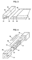
- antenna 1 includes feeding element 30, antenna core 31, feeder lead 34, magnetic member 35 and spacer 36.
- Antenna 1 according to the present invention can also be formed even when the spacer 36 is not used.
- Feeding element 30 is formed by helically winding a copper wire, copper foil and the like, and has opened end A at one end thereof, and feeder end B at the other end thereof.
- Antenna core 31 is made of an insulating member, and has a rectangular solid body. Feeding element 30 is provided on an outer circumferential portion of antenna core 31.
- Antenna core 31 is formed as of a resin, for example, ABS, phenol, polycarbonate or the like.
- feeder end B of feeding element 30 is electrically connected to feeder lead 34 by soldering.
- Feeding element 30 fundamentally works as an antenna.
- a current is fed to feeding element 30 via feeder lead 34, and antenna 1 can function as a ⁇ /4 mode resonance antenna by adjusting the width and length of a conductor constituting feeding element 30.
- antenna core 31 is described as an antenna core formed of an insulating material.
- This antenna core 31 can also be formed of a dielectric or a magnetic material.
- a wavelength of the antenna can be reduced, so that the miniaturization of the antenna can further be done.
Landscapes
- Engineering & Computer Science (AREA)
- Computer Networks & Wireless Communication (AREA)
- Support Of Aerials (AREA)
- Details Of Aerials (AREA)
Abstract
Description
Claims (9)
- An antenna comprising:a feeding element opened at one end thereof and having a feeder end at the other end thereof;an antenna core an outer circumference of which is provided with the feeding element;a feeder lead connected to the feeder end; anda magnetic member covering the feeder end.
- An antenna according to Claim 1, further comprising:wherein the parasitic element is provided on the feeding element with the insulator inserted therebetween.a parasitic element both ends of which are opened; andan insulator,
- An antenna according to Claim 1, further comprising an annular conductor provided at the antenna core,
wherein the conductor is connected to the feeding element and feeder lead. - An antenna according to Claim 1, wherein the antenna core is formed of a dielectric or a magnetic material.
- An antenna according to Claim 4, wherein the antenna core is made of an insulating member at the side of the opened end thereof, and a magnetic member at the side of the feeder end thereof.
- An antenna according to Claim 1, wherein the magnetic member has a draw-out recess from which the feeder lead is drawn out.
- An antenna according to Claim 1, further comprising a nonmagnetic spacer around an outer circumference of the side of the opened end of the feeding element.
- An antenna according to Claim 7, wherein the nonmagnetic spacer is formed of an insulating resin.
- An electronic device comprising:wherein the feeder lead of the antenna is connected to at least one of the transmission system and reception system.the antenna defined in Claim 1 or 2;a transmission system for executing the signal processing for the transmission of a signal; anda reception system for executing the signal processing for the reception of a signal,
Applications Claiming Priority (3)
| Application Number | Priority Date | Filing Date | Title |
|---|---|---|---|
| JP2003004449 | 2003-01-10 | ||
| JP2003004449 | 2003-01-10 | ||
| PCT/JP2003/016425 WO2004064193A1 (en) | 2003-01-10 | 2003-12-22 | Antenna and electronic device using same |
Publications (2)
| Publication Number | Publication Date |
|---|---|
| EP1496565A1 true EP1496565A1 (en) | 2005-01-12 |
| EP1496565A4 EP1496565A4 (en) | 2005-02-23 |
Family
ID=32708954
Family Applications (1)
| Application Number | Title | Priority Date | Filing Date |
|---|---|---|---|
| EP03768135A Withdrawn EP1496565A4 (en) | 2003-01-10 | 2003-12-22 | ANTENNA AND ELECTRONIC EQUIPMENT WITH THIS |
Country Status (4)
| Country | Link |
|---|---|
| US (1) | US7084825B2 (en) |
| EP (1) | EP1496565A4 (en) |
| CN (1) | CN100444464C (en) |
| WO (1) | WO2004064193A1 (en) |
Cited By (2)
| Publication number | Priority date | Publication date | Assignee | Title |
|---|---|---|---|---|
| WO2007105743A1 (en) * | 2006-03-10 | 2007-09-20 | Casio Computer Co., Ltd. | Antenna device and radio wave controlled timepiece |
| EP2234207A1 (en) * | 2009-03-23 | 2010-09-29 | Laird Technologies AB | Antenna device and portable radio communication device comprising such an antenna device |
Families Citing this family (7)
| Publication number | Priority date | Publication date | Assignee | Title |
|---|---|---|---|---|
| ES2617675T3 (en) * | 2004-10-28 | 2017-06-19 | Assa Abloy Ab | Safety sealing device comprising an RFID tag |
| US20080179275A1 (en) * | 2007-01-27 | 2008-07-31 | Kurt Himmelsbach | Cap for an NMR sample tube with inner sealing lip |
| JP4290744B2 (en) * | 2007-03-12 | 2009-07-08 | 株式会社日本自動車部品総合研究所 | Antenna device |
| US7714795B2 (en) * | 2007-08-23 | 2010-05-11 | Research In Motion Limited | Multi-band antenna apparatus disposed on a three-dimensional substrate, and associated methodology, for a radio device |
| US7629933B2 (en) * | 2007-08-23 | 2009-12-08 | Research In Motion Limited | Multi-band antenna, and associated methodology, for a radio communication device |
| USD611459S1 (en) * | 2008-06-19 | 2010-03-09 | Masprodenkoh Kabushikikaisha | EMC intense electric field antenna |
| JP2010130099A (en) * | 2008-11-25 | 2010-06-10 | Samsung Electronics Co Ltd | Antenna apparatus |
Family Cites Families (10)
| Publication number | Priority date | Publication date | Assignee | Title |
|---|---|---|---|---|
| US4160979A (en) * | 1976-06-21 | 1979-07-10 | National Research Development Corporation | Helical radio antennae |
| US5923305A (en) * | 1997-09-15 | 1999-07-13 | Ericsson Inc. | Dual-band helix antenna with parasitic element and associated methods of operation |
| EP0984510B1 (en) * | 1998-03-19 | 2006-06-14 | Matsushita Electric Industrial Co., Ltd. | Antenna device and mobile communication unit |
| WO2000072404A1 (en) | 1999-05-21 | 2000-11-30 | Matsushita Electric Industrial Co., Ltd. | Mobile communication antenna and mobile communication apparatus using it |
| KR20010058988A (en) * | 1999-12-30 | 2001-07-06 | 구기덕 | Antenna for cutting electromagnetic wave and manufacturing method thereof |
| JP3835128B2 (en) * | 2000-06-09 | 2006-10-18 | 松下電器産業株式会社 | Antenna device |
| JP3679338B2 (en) * | 2000-08-02 | 2005-08-03 | 株式会社ハネックス | RFID tag housing structure and installation structure |
| TW531976B (en) * | 2001-01-11 | 2003-05-11 | Hanex Co Ltd | Communication apparatus and installing structure, manufacturing method and communication method |
| JP3730926B2 (en) * | 2002-03-14 | 2006-01-05 | 京セラ株式会社 | Helical antenna design method |
| US20040198428A1 (en) * | 2002-05-31 | 2004-10-07 | Kye Systems Corp. | Miniature, high efficiency antenna device for enabling wireless communication with a computer system |
-
2003
- 2003-12-22 US US10/515,965 patent/US7084825B2/en not_active Expired - Fee Related
- 2003-12-22 WO PCT/JP2003/016425 patent/WO2004064193A1/en not_active Ceased
- 2003-12-22 EP EP03768135A patent/EP1496565A4/en not_active Withdrawn
- 2003-12-22 CN CNB2003801003774A patent/CN100444464C/en not_active Expired - Fee Related
Cited By (4)
| Publication number | Priority date | Publication date | Assignee | Title |
|---|---|---|---|---|
| WO2007105743A1 (en) * | 2006-03-10 | 2007-09-20 | Casio Computer Co., Ltd. | Antenna device and radio wave controlled timepiece |
| US7515112B2 (en) | 2006-03-10 | 2009-04-07 | Casio Computer Co Ltd | Antenna device and radio wave controlled timepiece |
| US7724199B2 (en) | 2006-03-10 | 2010-05-25 | Casio Computer Co., Ltd. | Antenna device and radio wave controlled timepiece |
| EP2234207A1 (en) * | 2009-03-23 | 2010-09-29 | Laird Technologies AB | Antenna device and portable radio communication device comprising such an antenna device |
Also Published As
| Publication number | Publication date |
|---|---|
| US7084825B2 (en) | 2006-08-01 |
| CN100444464C (en) | 2008-12-17 |
| CN1692525A (en) | 2005-11-02 |
| WO2004064193A1 (en) | 2004-07-29 |
| US20050156805A1 (en) | 2005-07-21 |
| EP1496565A4 (en) | 2005-02-23 |
Similar Documents
| Publication | Publication Date | Title |
|---|---|---|
| US7119743B2 (en) | Antenna and electronic device using the same | |
| JP4301034B2 (en) | Wireless device with antenna | |
| US6900768B2 (en) | Antenna device and communication equipment using the device | |
| US6417816B2 (en) | Dual band bowtie/meander antenna | |
| EP1560291A1 (en) | Wireless communication apparatus with a slit antenna | |
| CA2296519C (en) | Dual band antenna | |
| JPH06169217A (en) | Portable radio equipment | |
| KR20040082968A (en) | Surface-mounted chip antenna and communications equipment mounted the same thereon | |
| JP2000209020A (en) | Dielectric resonance antenna | |
| US20050001770A1 (en) | Antenna, antenna module and radio communication apparatus provided with the same | |
| US7084825B2 (en) | Antenna and electronic device using the same | |
| JPH09294013A (en) | Antenna device | |
| JP2005159727A (en) | Antenna device | |
| GB2328082A (en) | Antenna matching circuit for cordless telephone | |
| JP2003347815A (en) | Mobile radio equipment | |
| EP0982798B1 (en) | Antenna device and communication apparatus including the same | |
| EP1525679B1 (en) | Bias-t apparatus and center conductor of the same | |
| JP4048989B2 (en) | Antenna and electronic equipment using it | |
| JP3275513B2 (en) | Mobile communication equipment | |
| EP1489686B1 (en) | Antenna and electronic apparatus using it | |
| JPH08102617A (en) | Antenna device | |
| KR100569706B1 (en) | Appearance type antenna device using parasitic elements | |
| JPH10126134A (en) | Antenna device | |
| JP2000151251A (en) | Antenna | |
| JP2002305407A (en) | Portable wireless devices |
Legal Events
| Date | Code | Title | Description |
|---|---|---|---|
| PUAI | Public reference made under article 153(3) epc to a published international application that has entered the european phase |
Free format text: ORIGINAL CODE: 0009012 |
|
| 17P | Request for examination filed |
Effective date: 20040825 |
|
| AK | Designated contracting states |
Kind code of ref document: A1 Designated state(s): AT BE BG CH CY CZ DE DK EE ES FI FR GB GR HU IE IT LI LU MC NL PT RO SE SI SK TR |
|
| A4 | Supplementary search report drawn up and despatched |
Effective date: 20050112 |
|
| RIC1 | Information provided on ipc code assigned before grant |
Ipc: 7H 01Q 1/38 B Ipc: 7H 01Q 1/36 A Ipc: 7H 01Q 7/06 B Ipc: 7H 01Q 1/24 B Ipc: 7H 01Q 1/40 B |
|
| RBV | Designated contracting states (corrected) |
Designated state(s): DE FR GB |
|
| RIN1 | Information on inventor provided before grant (corrected) |
Inventor name: INUZUKA, TSUTOMU Inventor name: SATOH, YUKI Inventor name: YUDA, NAOKI Inventor name: SAKAE, MISAKO C/O MATSUSHITA ELECTRIC IND. CO. LTD |
|
| RIN1 | Information on inventor provided before grant (corrected) |
Inventor name: INUZUKA, TSUTOMUMATSUSHITA ELECTRIC IND. CO. LTD. Inventor name: SATOH, YUKI Inventor name: SAKAE, MISAKO C/O MATSUSHITA ELECTRIC IND. CO. LTD Inventor name: YUDA, NAOKI |
|
| RAP1 | Party data changed (applicant data changed or rights of an application transferred) |
Owner name: PANASONIC CORPORATION |
|
| 17Q | First examination report despatched |
Effective date: 20100518 |
|
| STAA | Information on the status of an ep patent application or granted ep patent |
Free format text: STATUS: THE APPLICATION IS DEEMED TO BE WITHDRAWN |
|
| 18D | Application deemed to be withdrawn |
Effective date: 20100929 |