EP1496297A2 - Vessel for well intervention - Google Patents
Vessel for well intervention Download PDFInfo
- Publication number
- EP1496297A2 EP1496297A2 EP04254129A EP04254129A EP1496297A2 EP 1496297 A2 EP1496297 A2 EP 1496297A2 EP 04254129 A EP04254129 A EP 04254129A EP 04254129 A EP04254129 A EP 04254129A EP 1496297 A2 EP1496297 A2 EP 1496297A2
- Authority
- EP
- European Patent Office
- Prior art keywords
- pipeline
- vessel
- wellbore
- drilling
- continuous casing
- Prior art date
- Legal status (The legal status is an assumption and is not a legal conclusion. Google has not performed a legal analysis and makes no representation as to the accuracy of the status listed.)
- Granted
Links
- 238000005553 drilling Methods 0.000 claims abstract description 110
- 239000012530 fluid Substances 0.000 claims abstract description 104
- 238000004519 manufacturing process Methods 0.000 claims abstract description 75
- 238000003860 storage Methods 0.000 claims abstract description 62
- 238000000034 method Methods 0.000 claims abstract description 58
- 229930195733 hydrocarbon Natural products 0.000 claims description 85
- 150000002430 hydrocarbons Chemical class 0.000 claims description 84
- 230000015572 biosynthetic process Effects 0.000 claims description 35
- 238000012545 processing Methods 0.000 claims description 34
- 239000004215 Carbon black (E152) Substances 0.000 claims description 30
- PEDCQBHIVMGVHV-UHFFFAOYSA-N Glycerine Chemical compound OCC(O)CO PEDCQBHIVMGVHV-UHFFFAOYSA-N 0.000 claims description 19
- 239000012188 paraffin wax Substances 0.000 claims description 3
- 239000002253 acid Substances 0.000 claims 1
- 238000005520 cutting process Methods 0.000 description 34
- 238000005755 formation reaction Methods 0.000 description 33
- XLYOFNOQVPJJNP-UHFFFAOYSA-N water Substances O XLYOFNOQVPJJNP-UHFFFAOYSA-N 0.000 description 31
- 230000008569 process Effects 0.000 description 9
- 239000007788 liquid Substances 0.000 description 8
- 238000009434 installation Methods 0.000 description 7
- 238000007789 sealing Methods 0.000 description 6
- 239000004568 cement Substances 0.000 description 5
- 238000004891 communication Methods 0.000 description 5
- 239000000203 mixture Substances 0.000 description 5
- 230000003247 decreasing effect Effects 0.000 description 4
- 230000032258 transport Effects 0.000 description 4
- 230000007423 decrease Effects 0.000 description 3
- 238000001556 precipitation Methods 0.000 description 3
- 238000000926 separation method Methods 0.000 description 3
- 241000239290 Araneae Species 0.000 description 2
- 238000004140 cleaning Methods 0.000 description 2
- 230000007797 corrosion Effects 0.000 description 2
- 238000005260 corrosion Methods 0.000 description 2
- ZSIAUFGUXNUGDI-UHFFFAOYSA-N hexan-1-ol Chemical compound CCCCCCO ZSIAUFGUXNUGDI-UHFFFAOYSA-N 0.000 description 2
- 230000036571 hydration Effects 0.000 description 2
- 238000006703 hydration reaction Methods 0.000 description 2
- 238000003780 insertion Methods 0.000 description 2
- 230000037431 insertion Effects 0.000 description 2
- 230000009545 invasion Effects 0.000 description 2
- 238000003801 milling Methods 0.000 description 2
- 238000012986 modification Methods 0.000 description 2
- 230000004048 modification Effects 0.000 description 2
- 230000008439 repair process Effects 0.000 description 2
- 239000007787 solid Substances 0.000 description 2
- 239000002699 waste material Substances 0.000 description 2
- 244000261422 Lysimachia clethroides Species 0.000 description 1
- 238000005452 bending Methods 0.000 description 1
- 239000002894 chemical waste Substances 0.000 description 1
- 238000007906 compression Methods 0.000 description 1
- 230000006835 compression Effects 0.000 description 1
- 239000004020 conductor Substances 0.000 description 1
- 239000000356 contaminant Substances 0.000 description 1
- 238000007796 conventional method Methods 0.000 description 1
- 238000001816 cooling Methods 0.000 description 1
- 238000007872 degassing Methods 0.000 description 1
- 238000010586 diagram Methods 0.000 description 1
- 238000007667 floating Methods 0.000 description 1
- 239000007789 gas Substances 0.000 description 1
- 125000001183 hydrocarbyl group Chemical group 0.000 description 1
- 238000002347 injection Methods 0.000 description 1
- 239000007924 injection Substances 0.000 description 1
- 238000002955 isolation Methods 0.000 description 1
- 238000012423 maintenance Methods 0.000 description 1
- 239000000463 material Substances 0.000 description 1
- 230000007246 mechanism Effects 0.000 description 1
- 238000012856 packing Methods 0.000 description 1
- 238000004886 process control Methods 0.000 description 1
- 238000003672 processing method Methods 0.000 description 1
- 238000005067 remediation Methods 0.000 description 1
- 239000002910 solid waste Substances 0.000 description 1
- 239000000126 substance Substances 0.000 description 1
- 238000012360 testing method Methods 0.000 description 1
Images



Classifications
-
- E—FIXED CONSTRUCTIONS
- E21—EARTH OR ROCK DRILLING; MINING
- E21B—EARTH OR ROCK DRILLING; OBTAINING OIL, GAS, WATER, SOLUBLE OR MELTABLE MATERIALS OR A SLURRY OF MINERALS FROM WELLS
- E21B7/00—Special methods or apparatus for drilling
- E21B7/20—Driving or forcing casings or pipes into boreholes, e.g. sinking; Simultaneously drilling and casing boreholes
- E21B7/201—Driving or forcing casings or pipes into boreholes, e.g. sinking; Simultaneously drilling and casing boreholes with helical conveying means
- E21B7/203—Driving or forcing casings or pipes into boreholes, e.g. sinking; Simultaneously drilling and casing boreholes with helical conveying means using down-hole drives
-
- B—PERFORMING OPERATIONS; TRANSPORTING
- B63—SHIPS OR OTHER WATERBORNE VESSELS; RELATED EQUIPMENT
- B63B—SHIPS OR OTHER WATERBORNE VESSELS; EQUIPMENT FOR SHIPPING
- B63B27/00—Arrangement of ship-based loading or unloading equipment for cargo or passengers
- B63B27/24—Arrangement of ship-based loading or unloading equipment for cargo or passengers of pipe-lines
-
- B—PERFORMING OPERATIONS; TRANSPORTING
- B63—SHIPS OR OTHER WATERBORNE VESSELS; RELATED EQUIPMENT
- B63B—SHIPS OR OTHER WATERBORNE VESSELS; EQUIPMENT FOR SHIPPING
- B63B35/00—Vessels or similar floating structures specially adapted for specific purposes and not otherwise provided for
-
- B—PERFORMING OPERATIONS; TRANSPORTING
- B63—SHIPS OR OTHER WATERBORNE VESSELS; RELATED EQUIPMENT
- B63B—SHIPS OR OTHER WATERBORNE VESSELS; EQUIPMENT FOR SHIPPING
- B63B35/00—Vessels or similar floating structures specially adapted for specific purposes and not otherwise provided for
- B63B35/44—Floating buildings, stores, drilling platforms, or workshops, e.g. carrying water-oil separating devices
- B63B35/4413—Floating drilling platforms, e.g. carrying water-oil separating devices
-
- E—FIXED CONSTRUCTIONS
- E21—EARTH OR ROCK DRILLING; MINING
- E21B—EARTH OR ROCK DRILLING; OBTAINING OIL, GAS, WATER, SOLUBLE OR MELTABLE MATERIALS OR A SLURRY OF MINERALS FROM WELLS
- E21B10/00—Drill bits
- E21B10/64—Drill bits characterised by the whole or part thereof being insertable into or removable from the borehole without withdrawing the drilling pipe
-
- E—FIXED CONSTRUCTIONS
- E21—EARTH OR ROCK DRILLING; MINING
- E21B—EARTH OR ROCK DRILLING; OBTAINING OIL, GAS, WATER, SOLUBLE OR MELTABLE MATERIALS OR A SLURRY OF MINERALS FROM WELLS
- E21B21/00—Methods or apparatus for flushing boreholes, e.g. by use of exhaust air from motor
- E21B21/08—Controlling or monitoring pressure or flow of drilling fluid, e.g. automatic filling of boreholes, automatic control of bottom pressure
- E21B21/085—Underbalanced techniques, i.e. where borehole fluid pressure is below formation pressure
-
- Y—GENERAL TAGGING OF NEW TECHNOLOGICAL DEVELOPMENTS; GENERAL TAGGING OF CROSS-SECTIONAL TECHNOLOGIES SPANNING OVER SEVERAL SECTIONS OF THE IPC; TECHNICAL SUBJECTS COVERED BY FORMER USPC CROSS-REFERENCE ART COLLECTIONS [XRACs] AND DIGESTS
- Y10—TECHNICAL SUBJECTS COVERED BY FORMER USPC
- Y10T—TECHNICAL SUBJECTS COVERED BY FORMER US CLASSIFICATION
- Y10T137/00—Fluid handling
- Y10T137/0318—Processes
- Y10T137/0402—Cleaning, repairing, or assembling
- Y10T137/0441—Repairing, securing, replacing, or servicing pipe joint, valve, or tank
- Y10T137/0458—Tapping pipe, keg, or tank
Definitions
- Embodiments of the present invention generally relate to an apparatus and method for intervening in offshore pipelines. Embodiments also relate to an apparatus and method for drilling and casing an offshore wellbore.
- Hydrocarbon production occurs either directly from the earth or from the earth below a body of water.
- Production directly from the earth is typically termed a "land production operation,” while production from the earth below a body of water is ordinarily typically termed an “offshore production operation” or a “subsea” production operation.”
- casing is inserted into a drilled-out wellbore within the earth formation. Casing isolates the wellbore from the formation, preventing unwanted fluids such as water from flowing from the formation into the wellbore.
- the casing is perforated at an area of interest within the formation which contains the desired hydrocarbons, and the hydrocarbons flow from the area of interest to the surface of the earth formation to result in the production of the hydrocarbons.
- hydrocarbons flow to the surface of the formation through production tubing inserted into the cased wellbore.
- Casing is inserted into the formation to form a cased wellbore by a well completion operation.
- the wellbore is formed to access hydrocarbon-bearing formations by the use of drilling.
- Drilling is accomplished by utilizing a cutting structure that is mounted on the end of a drill support member, commonly known as a drill string.
- a drill support member commonly known as a drill string.
- the drill string is often rotated by a top drive or rotary table on a surface platform or rig, or by a downhole motor mounted towards the lower end of the drill string.
- the drill string and its cutting structure are removed from the wellbore and a section of casing is lowered into the wellbore.
- annular area is thus formed between the string of casing and the formation.
- the casing string is temporarily hung from the surface of the well.
- a cementing operation is then conducted in order to fill the annular area with cement.
- the casing string is cemented into the wellbore by circulating cement into the annular area defined between the outer wall of the casing and the borehole. The combination of cement and casing strengthens the wellbore and facilitates the isolation of certain areas of the formation behind the casing for the production of hydrocarbons.
- the well is drilled to a first designated depth with a cutting structure on a drill string.
- the drill string is removed.
- a first string of casing or conductor pipe is then run into the wellbore and set in the drilled out portion of the wellbore, and cement is circulated into the annulus behind the casing string.
- the well is drilled to a second designated depth, and a second string of casing, or liner, is run into the drilled out portion of the wellbore.
- the second string is set at a depth such that the upper portion of the second string of casing overlaps the lower portion of the first string of casing.
- the second liner string is then fixed, or "hung" off of the existing casing by the use of slips which utilize slip members and cones to wedgingly fix the new string of liner in the wellbore.
- the second casing string is then cemented. This process is typically repeated with additional casing strings until the well has been drilled to total depth. In this manner, wells are typically formed with two or more strings of casing of an ever-decreasing diameter.
- drilling with casing is a method often used to place casing strings of decreasing diameter within the wellbore.
- This method involves attaching a cutting structure in the form of a drill bit to the same string of casing which will line the wellbore. Rather than running a cutting structure on a drill string, the cutting structure or drill shoe is run in at the end of the casing that will remain in the wellbore and be cemented therein.
- Drilling with casing is often the preferred method of well completion because only one run-in of the working string into the wellbore is necessary to form and line the wellbore per section of casing placed within the wellbore.
- Drilling with casing is especially useful in drilling and lining a subsea wellbore in a deepwater well completion operation.
- the initial length of wellbore that has been drilled is subject to potential collapse due to soft formations present at the ocean floor. Additionally, sections of wellbore that intersect areas of high pressure can cause damage to the wellbore during the time lapse between the formation of the wellbore and the lining of the wellbore. Drilling with casing minimizes the time between the drilling of the wellbore and the lining of the wellbore, thus alleviating the above problems.
- one option for storage and processing involves storing the hydrocarbons at a tank beside the wellbore, removing the hydrocarbons at time intervals from the storage unit with a mobile storage unit, physically transporting the hydrocarbons with the mobile storage unit to a processing unit, removing the hydrocarbons from the mobile storage unit and into the processing unit, and then processing the hydrocarbons at the processing unit.
- Another option for storing and processing the hydrocarbons in land production operations includes using a pipeline connected to the production tubing.
- the hydrocarbons flow from the formation through the perforations, into the production tubing, through the pipeline, and into a storage and processing unit at a remote location.
- the storage and processing unit typically receives multiple pipelines from multiple land production operations at various wellbores to allow storage and processing of hydrocarbons from multiple locations at one facility without the need for physically transporting the hydrocarbons to the processing unit.
- Offshore wells are often drilled and completed by use of a drilling rig.
- the drilling rig includes legs which rest on the floor of the body of water and support a rig floor.
- a hole is located in the rig floor of the drilling rig through which supplies for completing and drilling the wellbore, such as a drill string and casing strings, may be inserted and lowered into the body of water.
- the wellbore is typically drilled out by use of the drill string, then strings of casing are placed within the drilled-out wellbore to form a cased wellbore. Perforations are created in the casing and the formation as described above.
- a riser which is piping which spans the distance of the water from the ocean floor to the surface of the water, is ultimately inserted at the top of the cased wellbore. Because drilling rigs are relatively expensive to maintain above the wellbore after the completion operation, the drilling rig is removed from its location above the completed wellbore and employed to drill a subsequent wellbore at a different location. At this point, production of the hydrocarbons and subsequent storage of the hydrocarbons becomes an issue.
- One method for producing and storing hydrocarbons in offshore operations involves first building a production platform on the ocean floor. Like the drilling rig, the production platform includes a platform supported on legs which extend to the ocean floor. Production tubing is lowered from a hole which exists in the production platform into the riser and the cased wellbore to the area of interest which contains the perforations, then the hydrocarbons flow through the production tubing to a storage unit located on the production platform.
- the production platform is usually not large enough to accommodate the large volume of hydrocarbons which flow through the production tubing to the production platform; therefore, the production platform must only store hydrocarbons until a tanker arrives to transport the hydrocarbons from the storage unit to a larger storage and processing unit at another location. This method is expensive because each production platform above each wellbore which must be constructed and maintained represents a relatively large expense.
- a subsea well intervention vessel having processing equipment coupled to storage tanks and having well intervention equipment may be utilized to produce hydrocarbons through coiled tubing drilling or to store or process hydrocarbon mixtures produced from underbalanced drilling, as described in U.S. Publication Number 2003/0000740 published on January 2, 2003, filed by Haynes et al. and entitled "Subsea Well Intervention Vessel", which is herein incorporated by reference in its entirety.
- the intervention equipment is theoretically capable of reentering existing production wells without changing the wellbore from its production mode.
- a second method of producing and storing hydrocarbons in an offshore operation is more often practiced.
- the median step in the production and storage operation which includes the production platform is eliminated by satelliting. Satelliting involves installing pipelines at each wellbore and routing all of the pipelines to a common storage and processing location, typically termed a "satellite unit," through the pipelines. The pipelines remain underwater from the wellbore until reaching the storage and processing unit.
- a second problem which may result from the cold temperature of the water involves the changing temperatures of the hydrocarbons during their production.
- temperatures are high, causing the hydrocarbons to possess a high temperature.
- the hydrocarbons within the wellbore may contain both the liquid and gas phases.
- the environment within the water when the hydrocarbons travel through the pipelines consists of low temperatures.
- the temperature of the environment of the hydrocarbons becomes increasingly higher as the temperature increases with decreasing depth within the water.
- an intervention operation requires a remotely operated vehicle to raise the pipeline off the ocean floor, cut out the damaged section of pipe, install pipe connections on the cut ends of the pipeline, and then install and connect a new section of pipeline.
- Other intervention operations require stoppage of the flow of hydrocarbons through the pipeline to introduce treatment fluid into the pipeline to remove blockage within the pipeline.
- hydrocarbon flow must be halted during the intervention operation.
- Light intervention vessels are available which make it possible to conduct operations such as well servicing, e.g. well logging and general maintenance. Such vessels, however, cannot be considered appropriate platforms for interventions requiring drilling or hydrocarbon production as they are not sufficiently stable for such operations and are too small to handle the volumes of material that result from drilling. As such, the vessels must be supplemented with support vessels to receive produced hydrocarbons. Furthermore, light intervention vessels require large capital investments as compared with the returns that can be generated, particularly as they are highly vulnerable to bad weather such that intervention costs are relatively high and utilization time is relatively low. Even more cost is required to employ an additional support vessel. Because of the above disadvantages, no attempts have been made to use continuous casing to drill and line a wellbore from floating units or to allow hydrocarbon production during intervention operations in offshore wells.
- drilling with sections of casing minimizes the time between the drilling of the wellbore and the lining of the wellbore
- the present invention provides a method and apparatus for intervening in a pipeline, comprising providing a pipeline for transporting fluid flow from an offshore well to a location, diverting the fluid flow to a storage site, and intervening in the pipeline. Diverting the fluid flow to the storage site may comprise diverting the fluid flow to an offshore tanker while intervening in the pipeline from the offshore tanker.
- the present invention provides an apparatus for remediating an offshore pipeline and producing well fluids, comprising a vessel capable of storing well fluids flowing through the pipeline from a well, a first tubular body disposed within the vessel for diverting well fluid flow from the pipeline to the vessel for storing, and a second tubular body disposed within the vessel for remediating the pipeline.
- the vessel may be capable of diverting well fluid flow through the first tubular body while remediating the pipeline through the second tubular body and capable of remediating the pipeline without interruption of production of well fluids.
- the present invention provides a method of drilling a subsea wellbore from a vessel, comprising locating the vessel, the vessel having continuous casing, drilling the wellbore, and casing the wellbore with the continuous casing.
- Drilling and casing the wellbore may comprise drilling the wellbore with the continuous casing.
- the present invention provides a vessel for drilling an offshore wellbore, comprising a positionable vessel, continuous casing having an earth removal member operatively attached thereto disposed on the vessel for drilling the wellbore, and storage equipment disposed on the vessel for storing hydrocarbon fluid produced from the wellbore.
- the vessel may further comprise processing equipment connected to the storage equipment for processing the hydrocarbon fluid produced from the wellbore.
- the present invention advantageously allows offshore or subsea intervention operations to occur within a pipeline while simultaneously producing hydrocarbons from the pipeline, thus increasing profitability of the wellbore. Further, the present invention permits formation of an offshore or subsea cased wellbore with one run-in of the casing, and also allows for storage and/or processing of hydrocarbons during the drilling process on the same vessel which houses the equipment used to form the cased wellbore, increasing the profitability of the wellbore.
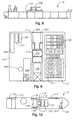
- Figure 8 illustrates a vessel 10 embodying the present invention.
- Figure 8 is based on a drawing extracted from "First Olsen Tankers” and shows a shuttle tanker of the type widely used in the North Sea.
- the only modification made to the standard shuttle tanker is the mounting of a superstructure 107 above the main deck (not shown) of the vessel 10, for example at a height of approximately 3 meters so as to exist above the installed deck pipes and vents (not shown).
- a standard North Sea specified shuttle tanker with dynamic positioning can be readily charted and fitted with a new deck above the installed deck pipes and vents, upon which deck can be installed, for example, the following equipment: a skid mounted derrick riser handling unit with subsea control panel; stumps for the subsea well intervention equipment; a pipe rack; coiled tubing reels, a control unit, and a power pack; a cementing unit and blender, production test equipment including a choke manifold, heater treater, separators, degassing boot and gas flare; tanks for kill mud; a closed circulation system for handling drilling mud and drilled solids during underbalanced drilling; storage tanks for chemical and solid wastes; cranes for subsea equipment and supplies; remote controlled vehicles for working and observation tasks; and water supplies for cooling and fire fighting services (see below). All the equipment necessary for pipeline intervention and/or drilling is mounted on the superstructure 107, including a crane 108. The detailed layout of the equipment mounted on the superstructure 107 of Figure 8 is shown in
- a skid deck 109 is centrally mounted on the superstructure 107 adjacent a gantry crane 110.
- a riser deck and laydown area 335 On the other side of the gantry crane 110 is a riser deck and laydown area 335.
- a subsea laydown area and equipment stumps 340 Between the crane 108 and the skid deck 109 are a subsea laydown area and equipment stumps 340, remotely operated vehicles 341, and a subsea control unit 342.
- a gas compressor 343, air compressor 344, and firewater pumps 345 Also located on the superstructure 107 are a gas compressor 343, air compressor 344, and firewater pumps 345.
- Coiled tubing drilling equipment 111 of conventional form is mounted adjacent the gantry crane 110, including but not limited to a laydown area, power pack, control unit, goose neck, injector head, conveyor, reels, and blowout preventers.
- a slickline contractor 302 and an electric line contractor 301 may be disposed by the coiled tubing drilling equipment 111.
- a separator assembly 112 and ancillary drilling support equipment assembly 106 are also mounted on the superstructure 107.
- the separator assembly 112 may include, but is not limited to, separators 310A-D, chokes 311, a heater treater 312, a cuttings treatment unit 313, mud cleaning unit 314, produced water cleaning unit 315, metering gas oil unit 316, and chemical injection unit 317.
- the ancillary drilling support equipment assembly 106 may include but is not limited to kill mud unit 320, completion fluid unit 321, active mud tanks 322 and 323, hexanol (HeOH) unit 324, spare unit 325, waste unit 326, cuttings waste unit 327, mud pumps 328, and cement unit 329.
- a process control unit 330 and a laboratory 331 Between the drilling support equipment assembly 106 and the separator assembly 112 are a process control unit 330 and a laboratory 331. All other equipment relied upon to achieve the required direct well intervention is also mounted on the superstructure 107.
- the separator assembly 112 is connected to an appropriately positioned flare stack (not shown), for example at the stern (not shown) of the vessel 10 and to the storage tanks (not shown) of the vessel 10 so as to enable produced hydrocarbon fluids to be stored for subsequent transport.
- the vessel 10 is dynamically positioned above a subsea well or pipeline.
- the skid deck 109 is then moved to an outboard position (not shown) over the subsea well or the pipeline to enable the coiled tubing equipment 111 to be coupled to a riser above the subsea well for drilling or to a tap 80 or 90 (see Figures 1-4) installed within the pipeline 20.
- Appropriate interventions can then be made via the tubular member or coiled tubing drilling can be conducted in a manner which produces a multiphase mixture of the hydrocarbon fluid that is subsequently separated into its different phases in the separator assembly 112.
- FIG 10 shows an alternate arrangement of the vessel 10 for mounting equipment for use with the present invention.
- the drilling and/or intervention equipment could be mounted adjacent a moon pool 113 or 114 extending through the deck of the vessel 10.
- the components are mounted adjacent moon pools 113 and 114 extending vertically through the structure of the vessel 10.
- Three cranes 115, 116, and 117 can extend over the moon pools 113 and 114 and areas indicating cargo manifolds 118, a derrick module 119, and a lay down area 120.
- Area 121 houses gas compression and process units, area 122 a flare boom, area 123 a flare knock-out drum skid, and area 124 a further lay down area served by a crane 125.
- the modifications required to produce the vessel 10 illustrated in Figure 10 which can function in accordance with the present invention would include an upgrade of the dynamic positioning capability, installation of a first moon pool for intervention and/or drilling work, installation of a second moon pool for remotely operated vehicle work, mounting of cranes, process equipment and lay down areas for deck-mounted equipment, and the mounting of flare facilities and associated utilities.
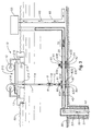
- FIGS 1-4 show the vessel 10 of the present invention, which is capable of diverting flow from a pipeline 20 and/or remediating the pipeline 20 during a satellite pipeline operation.
- a superstructure 215 mounted on legs 216 exists on the vessel 10 and has a hole 218 therein for lowering intervention equipment therethrough.
- the vessel 10, in the embodiment shown, includes a hole 213 in its floor essentially in line with the hole 218 for lowering intervention equipment therethrough.
- the pipeline 20 in the satellite pipeline operation, the pipeline 20 is located at or near the floor 30 of a body of water 40.
- the pipeline 20 initially transports well fluid 45, typically hydrocarbon fluid, from a wellbore 50 disposed in the floor 30 to a satellite storage unit 55 disposed at least partially above a surface 60 of the body of water 40.
- the wellbore 50 is drilled into the floor 30 to a depth at which well fluid 45 exists.
- the wellbore 50 may be completed with casing 51, as shown in Figures 1-4, or may remain an open hole wellbore with no casing disposed therein.
- the pipeline 20 is connected to production tubing 52.
- the production tubing 52 is located within the wellbore 50 and extends at least to an area of interest (not shown) in the floor 30, which is a depth at which the well fluid 45 exists.
- the production tubing 52 typically includes packing elements (not shown) disposed around its outer diameter which extend to the wellbore 50 above and below the area of interest in the floor 30 to isolate the area of interest within the wellbore 50.
- Perforations are inserted into the production tubing 52 across from the area of interest in the wellbore 50, and perforations (not shown) are likewise inserted into the area of interest in the wellbore 50.
- Well fluid 45 thus flows from the area of interest in the wellbore 50 into an annular area 53 between the outer diameter of the production tubing 52 and the wellbore 50, then up through the production tubing 52 disposed within the wellbore 50 and into the pipeline 20.
- the satellite storage unit 55 is capable of storing well fluid 45 received from the pipeline 20.
- the satellite storage unit 55 may also possess well fluid processing capabilities.
- the satellite storage unit 55 may also receive well fluid 60 from any number of additional pipelines 65.
- Each additional pipeline 65 is connected to production tubing (not shown) inserted within a wellbore (not shown), as described above in relation to production tubing 52 within the wellbore 50, at a different location within the floor 30 than the wellbore 50.
- a problem area 70 exists in the pipeline 20 which must be treated in some manner to resume the desired well fluid 45 flow through the pipeline 20.
- the problem area 70 may include, but is not limited to, partial or total blockage of flow in the pipeline 20 due to precipitation build-up on the inside of the pipeline 20 which must be removed from the pipeline 20, paraffin deposits on the inside of the pipeline 20 which must be descaled or removed, or gas hydration within the pipeline 20.
- the problem area 70 may also include bends, holes, or corrosion damage to the pipeline 20 which must be repaired. Additionally, the problem area 70 may include stuck equipment which must be dislodged from within the pipeline such as a stuck pig.
- the intervention may include dislodging stuck equipment, removing build-up or deposits in the pipeline 20 causing partial or total blockage of the pipeline 20, and/or repairing damage to the pipeline 20.
- the pipeline 20 must be physically invaded in some fashion to fix the problem area 20 and restore ordinary fluid flow 45 from the wellbore 50 to the satellite storage unit 55.
- the vessel 10 or tanker of the present invention is employed to fix the problem area 20.
- the vessel 10 may be disposed on the surface 60 of the water 40, partially below the surface 60, or completely below the surface 60.
- a second tubular body 12 preferably coiled tubing.
- a first tubular body 11, also preferably coiled tubing, extends from the vessel 10 into the water 40.
- the first tubular body 11 may be inserted into a riser pipe (not shown) which extends from the vessel 10 to the floor 30.
- the first tubular body 11 is sealably connected to a storage tank 13 for storing produced well fluid 45 from the wellbore 50, which may be connected to a processing unit (not shown) on the vessel 10 for processing well fluid 45.
- the processing unit may include liquid separation equipment.
- the first tubular body 11 may comprise three tubular sections, including 11A, 11B, and 11C. At its lower end, tubular section 11A is connected, preferably threadedly connected, to an upper end of tubular section 11B.
- Tubular section 11B is a portion of a blow out preventer 9.
- the blow out preventer 9 includes a large valve 8 which may be closed to control well fluids 45. The valve 8 is typically closed remotely through hydraulic actuators (not shown).
- Tubular section 11B is connected, preferably threadedly connected, at its lower end to an upper end of tubular section 11C.
- first tap 80 Connected to the pipeline 20 in Figure 1 is a first tap 80 which is capable of fluid communication with the pipeline 20 through a first hole 84 in the pipeline 20.
- the first tap 80 is a tubular body having a valve 81 disposed therein for selective disruption of fluid flow through the tubular body.
- the first tap 80 is connected to the pipeline 20 through a first clamp 82 disposed around the pipeline 20 and is held in sealing engagement with the pipeline 20 due to sealing members 83A, 83B, 83C, and 83D. Any number of sealing members 83A-D may be employed to secure sealed fluid communication between the first tap 80 and the pipeline 20.
- a second tap 90 is installed in the pipeline 20 between the problem area 70 and the first tap 80.
- the second tap 90 is a tubular body with a second valve 91 therein to selectively obstruct fluid flow through the tubular body.
- a second clamp 92 is sealably disposed around the pipeline 20 by sealing members 93A-D to provide sealed fluid communication between the second tap 90 and the pipeline 20 through a second hole 94 in the pipeline 20.
- the wellbore 50 is drilled into the floor 30 and lined with casing 51, and the pipeline 20 is connected at one end to production tubing 52 within the wellbore 50 and at the opposite end to the satellite storage unit 55.
- Fluid flow 45 continues essentially uninhibited through the pipeline 20 from the area of interest in the wellbore 50 to the satellite storage unit 55 until a problem area 70 develops in the pipeline.
- the vessel 10 is located above the pipeline 20 near the problem area 70 to conduct a pipeline intervention operation and remove or repair the problem area 70.
- a first tap 80 is installed into the pipeline 20 between the problem area 70 and the wellbore 50.
- a cutting tool such as a milling tool, which is known to those skilled in the art, may be utilized to drill the first hole 84 in the pipeline 20.
- the first clamp 82 is opened and positioned around the pipeline 20 at the desired point of insertion of the first tap 80.
- the sealing members 83A-D disposed between the first clamp 82 and the pipeline 20 are used to produce and maintain a fluid-tight sealed connection between the first tap 80 and the pipeline 20.
- the first tubular member 11 is lowered from the vessel 10 through the hole 113 in the floor of the vessel 10, which may be the skid deck 109 in the outboard position of Figures 8-9 or the moon pool 113 or 114 of Figure 10, depending upon the configuration of the vessel 10 which is used.
- the lower end of the first tubular member 11 is connected, preferably threadedly connected, to the upper end of the first tap 80.
- the first valve 81 is then opened to allow well fluid 45 to flow along a sealed path from the perforations in the wellbore 50 into the production tubing 52 through the perforations in the production tubing 52, and into the pipeline 20.
- the fluid flow 45 is diverted from further flow through the pipeline 20 to flow up through first tap 80 and the first tubular member 11 into the storage tank 13.
- the well fluid 45 may be diverted to the processing unit which may exist on the vessel 10, or, in the alternative, may eventually be transported to another facility for processing.
- Figure 2 shows production of the well fluid 45 diverted through the first tap 80 to the vessel 10 for storage and/or processing.
- the intervention may be accomplished without interruption of the production of the well fluid 45.
- External patching or bending of the problem area 70 may be conducted without the installation of the additional second tap 90 if the problem area 70 is a hole or bend. If it is desired to intervene into the pipeline 20 by introduction of an object (not shown) or a treatment fluid 21 (see Figure 4) into the pipeline 20, the second tap 90 may be installed on the pipeline 20 between the problem area 70 and the first tap 80.
- Installation of the second tap 90 proceeds much as the installation of the first tap 80.
- the second valve 91 is in the closed position during the installation of the second tap 90.
- the cutting tool such as the milling tool may be utilized to drill the second hole 94 in the pipeline 20.
- a whipstock (not shown) may be used to guide the cutting tool (e.g., mill) into the pipeline 20 at an angle, as is known in relation to drilling deviated wellbores from parent wellbores.
- the second clamp 92 is then opened and positioned around the pipeline 20 at the desired point of insertion of the second tap 90.
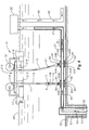
- FIG. 3 shows the second tap 90 installed at the pipeline 20 between the problem area 70 and the first tap 80, with the second valve 91 in the closed position.
- the lower end of the second tubular body 12 is connected, preferably threadedly connected, to an upper end of the second tap 90.
- the second valve 91 is then opened to allow fluid communication between the vessel 10 and the pipeline 20. If it is desired to introduce an object into the second tubular body 12, then the object may be directly introduced into the upper end of the second tubular body 12. If, as is shown in Figure 4, it is desired to introduce treatment fluid 21 into the pipeline 20 to dislodge, disband, or dissolve partial or total blockage existing in the problem area 70, a storage tank 22 with the treatment fluid 21 housed therein is connected to the upper end of the second tubular body 12.
- the treatment fluid 21 is then introduced into the second tubular body 12 to flow through the second tap 90 and into the pipeline 20 toward the problem area 70.
- the treatment fluid 21 may be separated from the well fluids present at the satellite storage unit 55 until the pipeline 20 flow between the wellbore 50 to the satellite storage unit 55 is restored.
- Figure 4 shows the intervention operation conducted through the second tap 90 and the pipeline 20 while production of the well fluid 45 continues uninterrupted from the wellbore 50, through the first tap 80, and into the vessel 10.
- the pipeline intervention operation is conducted until the problem area 70 is effectively treated and no longer a threat to production of the well fluid 45.
- the treatment fluid 21 flow is halted so that treatment fluid 21 is no longer introduced into the second tubular body 12 from the vessel 10.
- the second valve 91 is then closed and the second tubular body 12 disconnected from the second tap 90.
- the first valve 81 is closed and the first tubular member 11 disconnected from the first tap 80.
- the first tubular member 11 as well as the second tubular member 12 is then retrieved to the vessel 10.
- the resumed well fluid 45 flow through the pipeline 20 is ultimately essentially unaffected by the pipeline intervention operation.
- Closing the valves 91, 81 obstructs the alternate paths for the well fluid 45 flow which existed during the intervention operation.
- Well fluid 45 may again flow from the wellbore 50 through the production tubing 52, into the pipeline 20, through the former problem area 70, and up into the satellite storage unit 55 for storage and/or processing.
- the production of well fluid 45 was accomplished either into the storage tank 13 or into the satellite storage unit 55 without interruption through the present invention.
- the above intervention method and apparatus may be utilized not only in repairing a problem area 70 in the pipeline 20, but also in installing and retrieving subsea equipment.
- the alternate route through the first tap 80 and the first tubular member 11 may be utilized to divert well fluid 45 flow while installing or retrieving equipment within the water 40 when the installing or retrieving involves physical invasion of the pipeline 20.
- the vessel 10 may be utilized to drill into a formation 201 within the floor 30 of the body of water 40 using continuous casing 210.
- Figures 5-7 show the embodiment of the vessel 10 which is depicted in Figure 10, as the moon pool 113 is located in the bottom of the vessel 10.
- the skid deck 109 arrangement of Figures 8-9 may also be utilized to communicate the continuous casing 210 into the formation 201 from the vessel 10.
- the vessel 10 has a superstructure 215 disposed thereon, which is supported above the vessel floor 217 by legs 216.
- a hole 218 is disposed in the superstructure 215 above the moon pool 113 and substantially in axial line with the moon pool 113.
- Equipment utilized in the drilling process is lowered through the hole 218 in the superstructure 215 and the moon pool 113 at various stages of the operation.
- a riser pipe 221 extends from the moon pool 113 to the ocean floor 30.
- the riser pipe 221 provides a path through the body of water 40 to the floor 30 through which the continuous casing 210 may be lowered.
- the continuous casing 210 is located on the superstructure 215 on a reel 225.
- a drilling fluid source 226 is in fluid communication at some location with the continuous casing 210 to provide drilling fluid to the continuous casing 210 at various stages of the drilling operation.
- a spider 227 or other gripping apparatus having gripping members such as slips is also disposed on the superstructure 215 around or within the hole 218 to act as a back-up gripping device during the drilling operation for the continuous casing 210.
- an injector head 230 is disposed on the superstructure 215.
- the injector head 230 includes conveying members 232 and 233, which are substantially centered around the hole 218 and suspended above the hole 218 by supports 234 and 235.
- the conveying members 232 and 233 of the injector head 230 act essentially as conveyor belts and are moveable clockwise and counterclockwise around the axis of the conveying members 232 and 233 to lower or retrieve the continuous casing 210 into or out from the hole 218.
- the conveyor belt 240 on the track 241 is located between the reel 225 and the injector head 230 to obtain the continuous casing 210 from the reel 225 and feed the continuous casing 210 into the injector head 230, or to return the continuous casing 210 to the reel 225 from the injector head 230.
- the injector head 230 and the conveyor belt 240 on the track 241, as described above, are known to those skilled in the art as a method of feeding continuous tubing. Other aspects of the method of feeding continuous tubing or continuous casing to drill a wellbore known to those skilled in the art are contemplated for use with the present invention.
- the continuous casing 210 includes a mud motor 245 disposed therein connected by a releasable connection 246 to the inner diameter of the continuous casing 210.
- An expandable cutting structure 250 with perforations 260 therethrough for circulating drilling fluid and/or setting fluid is attached to the mud motor 245.
- the expandable cutting structure 250 includes a body (not shown) and a blade assembly (not shown) disposed on the body, as is disclosed in co-pending U.S. Patent Application Serial Number 10/335,957 filed on December 31, 2002, which is herein incorporated by reference in its entirety.
- the blade assembly is movable between a closed position whereby the expandable cutting structure 250 has a smaller outer diameter and an open position whereby the expandable cutting structure 250 has a larger outer diameter.
- the blade assembly may be moveable between the open position and the closed position through a hydraulic pressure differential created across nozzles (not shown) within the expandable cutting structure 250.
- the expandable cutting structure 250 may further include a release assembly for providing a secondary means to move the blade assembly from the open position to the closed position, as disclosed in the above-referenced application.
- the mud motor 245 may include a shaft (not shown) and a motor operating system (not shown).
- the mud motor 245, which is the mechanism for rotating the cutting structure 250, is hollow to allow for fluid flow therethrough at various stages of the drilling operation and is preferably a hydraulic mud motor operated by fluids pumped therethrough.
- the motor operating system turns the shaft, which rotates the expandable cutting structure 250 for drilling into the formation 201.
- the described mud motor 245 is not the only mud motor available for use with the present invention, as other types of mud motors which are known to those skilled in the art are contemplated for use with the present invention.
- the vessel 10 may include hydrocarbon fluid separation equipment (not shown) coupled to one or more storage units (not shown) to receive separated hydrocarbon fluids from the wellbore 270.
- hydrocarbon fluid separation equipment not shown
- storage units not shown
- the vessel can collect produced hydrocarbon fluid during drilling with the continuous casing 210, thus eliminating the need for a separate vessel in the event that hydrocarbon fluid is produced during drilling.
- the vessel 10 is located above the floor 30 of the body of water 40, at or near the surface 60 of the body of water 40, so that the hole 218 in the superstructure 215 and the moon pool 113 are substantially aligned with the location at which it is desired to drill into the formation 201.
- the riser pipe 221 is lowered through the moon pool 113 to connect the vessel floor 217 to the floor 30 of the body of water 40 so that the continuous casing 210 and/or other tools may be lowered into the formation 201 without the interference of the body of water 40 in the drilling process.
- the continuous casing 210 is then pulled from the reel 225 onto the conveyor belt 240, and the conveyor belt 240 moves counterclockwise along the track 241 to feed the continuous casing 210 into the injector head 230 between the conveying members 232 and 233.
- the expandable cutting structure 250 is retracted at this point in the operation.
- the gripping members of the spider 227 are unactivated.
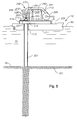
- Figure 5 illustrates this stage in the drilling operation.
- the continuous casing 210 is lowered through the hole 218 in the superstructure 215, through the moon pool 113, and through the riser pipe 221.
- the expandable cutting structure 250 is expanded, preferably due to hydraulic pressure.
- the continuous casing 210 is then lowered into the formation 201 while the mud motor 245 imparts torque to the cutting structure 250, thereby drilling a wellbore 270.
- drilling fluid is circulated from the drilling fluid source 226 into the continuous casing 210, then into the mud motor 245, through the perforations 260 in the expandable cutting structure 250, up through an annulus 275 between the continuous casing 210 and the wellbore 270, up through an annulus 280 between the continuous casing 210 and the riser pipe 221, and up to the vessel 10 for storage or recirculation.
- the fluid is circulated to carry cuttings and/or debris from the formation 201, which are produced to the surface during drilling, and to facilitate a path for the drilling of the continuous casing 210 into the formation 201.
- Figure 6 shows the continuous casing 210 drilling into the formation 201.
- the continuous casing 210 is drilled to the desired depth within the formation 201.
- setting fluid is introduced into the continuous casing 210 and circulated into the annulus 275 to set the continuous casing 210 within the wellbore.
- the expandable cutting structure 250 is then retracted to allow it to fit through the continuous casing 210, and a cutting tool (not shown) is utilized to sever the continuous casing 210 at the floor 30.
- the conveyor 240 may be manipulated to move clockwise around the track 241 to return the cut-off portion of the continuous casing 210 residing above the floor 30 to the reel 225.
- a wireline 290 is lowered from the superstructure 215.
- the wireline 290 is manipulated into a slot 291 located within the mud motor 245 and then pulled upward, pushed downward, or turned (when the releasable connection 246 is a threadable connection) to release the releasable connection 246, which is preferably a shearable connection which is sheared by pulling upward or pushing downward on the wireline 290. Releasing the releasable connection 246 allows the mud motor 245 and expandable cutting structure 250 to be moveable with respect to the continuous casing 210.
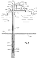
- Figure 7 shows the wireline 290 retrieving the expandable cutting structure 250 and the mud motor 245 from within the continuous casing 210.
- the wireline 290 is pulled through the moon pool 113 to the vessel 10 along with the expandable cutting structure 250 and the mud motor 245. Any other apparatus and method for retrieving the mud motor 245 and the cutting structure 250 known by those skilled in the art may be utilized with the present invention.
- the drilling method of Figures 5-7 and the vessel 10 which is used to accomplish the drilling advantageously allow the wellbore 270 to be drilled into the formation 201 with one run-in of the continuous casing 210.
- the wellbore 270 is now ready for subsequent operations such as hydrocarbon production operations.
- the same vessel 10 which was used for continuous casing 210 drilling described in Figures 5-7 may also be utilized for intervention operations described in Figures 1-4 if a pipeline 20 is used to produce fluids 45 from the wellbore 270 to the satellite storage unit 55.
- the drilling method of Figures 5-7 is especially useful when employing the vessel 10 when drilling an offshore wellbore 270 in an underbalanced condition.
- Drilling in an underbalanced condition involves maintaining a positive pressure at the surface of the wellbore 270.
- Underbalanced drilling avoids damage to the wellbore 270 which can result from overbalanced drilling conditions when the drilling fluids invade the formation 201.
- Underbalanced drilling allows more efficient and faster hydrocarbon production from the formation 201. Because underbalanced wells produce significant volumes of hydrocarbons, the smaller remotely operated vehicles available are insufficient to store the produced fluids.
- the vessel 10 is capable of storing the volumes of fluid produced during underbalanced drilling.
- the produced hydrocarbon fluid is a multiphase mixture of gas, solids, and liquids requiring separation.
- the drilling method of Figures 5-7 allows the capabilities of drilling with continuous casing 210, producing the hydrocarbons, storing the hydrocarbons with the storage equipment, and separating the produced multiphase mixture with the separating equipment using the same vessel 10.
- underbalanced drilling and the problems especially problems with the resulting multiphase mixture, encountered when drilling underbalanced, refer to U.S. Patent Application Number 10/192,784, entitled “Closed Loop Multiphase Underbalanced Drilling Process", filed on July 10, 2002 by Chitty et al., which is incorporated by reference in its entirety herein.
Landscapes
- Engineering & Computer Science (AREA)
- Mining & Mineral Resources (AREA)
- Geology (AREA)
- Life Sciences & Earth Sciences (AREA)
- Mechanical Engineering (AREA)
- Chemical & Material Sciences (AREA)
- Combustion & Propulsion (AREA)
- Ocean & Marine Engineering (AREA)
- Physics & Mathematics (AREA)
- Environmental & Geological Engineering (AREA)
- Fluid Mechanics (AREA)
- General Life Sciences & Earth Sciences (AREA)
- Geochemistry & Mineralogy (AREA)
- Structural Engineering (AREA)
- Civil Engineering (AREA)
- Architecture (AREA)
- Earth Drilling (AREA)
- Physical Or Chemical Processes And Apparatus (AREA)
Abstract
Description
Claims (44)
- A method of intervening in a pipeline, comprising:providing a pipeline for transporting fluid flow from an offshore well to a location;diverting the fluid flow to a storage site; andintervening in the pipeline.
- The method of claim 1, wherein the well is underbalanced.
- The method of claim 1 or claim 2, wherein diverting the fluid flow to the storage site comprises diverting the fluid flow to an offshore tanker.
- The method of any preceding claim, wherein diverting the fluid flow to the storage site comprises inserting a tap into the pipeline and flowing the fluid flow through the tap to the storage site.
- The method of claim 4, wherein the tap is inserted into the pipeline between the well and the storage site.
- The method of any preceding claim, wherein intervening in the pipeline comprises inserting a tap into the pipeline downstream from the diversion of fluid flow to the storage site.
- The method of claim 6, wherein coiled tubing is lowered from the storage site and inserted into the tap for intervening in the pipeline.
- The method of claim 7, wherein the coiled tubing is lowered through a moon pool disposed in the vessel.
- The method of claim 7, wherein the coiled tubing is lowered through a skid deck displaced to an outboard position.
- The method of any preceding claim, wherein intervening in the pipeline occurs downstream with respect to initial fluid flow through the pipeline to the location from the diverting of the fluid flow to the storage site.
- The method of any preceding claim, wherein intervening in the pipeline comprises removing blockage of the fluid flow within the pipeline.
- The method of claim 11, wherein removing blockage comprises injecting acid through coiled tubing inserted in the pipeline.
- The method of claim 11, wherein removing blockage comprises drilling into the pipeline and physically removing the blockage.
- The method of any of claims 1 to 10, wherein intervening comprises removing a pig stuck in the pipeline.
- The method of any of claims 1 to 10, wherein intervening comprises descaling the pipeline.
- The method of any of claims 1 to 10, wherein intervening comprises removing paraffin from within the pipeline.
- The method of any of claims 1 to 10, wherein intervening comprises repairing damage to the pipeline.
- The method of any of the preceding claim, wherein the diverting and the intervening are accomplished from the same location.
- The method of claim 18, wherein the location is an offshore tanker.
- An apparatus for remediating an offshore pipeline and producing well fluids, comprising:a vessel capable of storing well fluids flowing through the pipeline from a well;a first tubular body disposed on the vessel for diverting well fluid flow from the pipeline to the vessel for storing; anda second tubular body disposed on the vessel for remediating the pipeline.
- The apparatus of claim 20, wherein the first tubular body and the second tubular body are mounted on a superstructure above a main deck of the vessel.
- The apparatus of claim 20 or 21, wherein the vessel is capable of diverting well fluid flow through the first tubular body while remediating the pipeline through the second tubular body.
- The apparatus of claim 22, wherein the vessel is capable of remediating the pipeline without interruption of production of well fluids.
- The apparatus of any of claims 20 to 23, wherein the first tubular body is a riser.
- The apparatus of any of claims 20 to 24, wherein the second tubular body is coiled tubing.
- The apparatus of any of claims 20 to 25, wherein the first tubular body is connected to a first tap inserted into the pipeline.
- The apparatus of claim 26, wherein the second tubular body is connected to a second tap inserted into the pipeline.
- The apparatus of claim 27, wherein the second tap is inserted into the pipeline downstream from the first tap inserted into the pipeline.
- The apparatus of any of claims 20 to 28, wherein the vessel is capable of processing well fluids flowing through the pipeline from the well.
- A method of drilling a subsea wellbore from a vessel, comprising:locating the vessel, the vessel having continuous casing;drilling the wellbore; andcasing the wellbore with the continuous casing.
- The method of claim 30, wherein drilling the wellbore comprises drilling the wellbore with the continuous casing.
- The method of claim 31, wherein drilling the wellbore with continuous casing comprises lowering the continuous casing through a moon pool disposed within the vessel and drilling the continuous casing into a formation.
- The method of claim 31, wherein drilling the wellbore with continuous casing comprises lowering the continuous casing through a skid deck displaced to an outboard position and drilling the continuous casing into a formation.
- The method of any of claims 31 to 33, wherein the wellbore is underbalanced while drilling with the continuous casing.
- The method of any of claims 31 to 34, wherein drilling the wellbore with the continuous casing comprises drilling the wellbore using an earth removal member operatively attached to a lower end of the casing.
- The method of any of claims 30 to 35, further comprising receiving production fluid from the wellbore with the vessel.
- The method of claim 36, further comprising storing production fluid from the wellbore on the vessel.
- The method of claim 36 or 37, further comprising processing production fluid from the wellbore using processing equipment located on the vessel.
- The method of claim 38, wherein the processing equipment and the continuous casing are within a closed loop.
- A vessel for drilling an offshore wellbore, comprising:a vessel;continuous casing having an earth removal member operatively attached thereto disposed on the vessel for drilling the wellbore; andstorage equipment disposed on the vessel for storing hydrocarbon fluid produced from the wellbore.
- The vessel of claim 40, wherein the continuous casing is mounted on a superstructure above a main deck of the vessel.
- The vessel of claim 40, wherein the continuous casing is mounted adjacent a skid deck which may be displaced to an outboard position through which the continuous casing is lowered for drilling.
- The vessel of claim 40, wherein the continuous casing is mounted adjacent a moon pool through which the continuous casing is lowered for drilling.
- The vessel of any of claims 40 to 43, further comprising fluid processing equipment coupled to the storage equipment for processing the hydrocarbon fluid.
Applications Claiming Priority (2)
| Application Number | Priority Date | Filing Date | Title |
|---|---|---|---|
| US618093 | 2003-07-11 | ||
| US10/618,093 US7650944B1 (en) | 2003-07-11 | 2003-07-11 | Vessel for well intervention |
Publications (3)
| Publication Number | Publication Date |
|---|---|
| EP1496297A2 true EP1496297A2 (en) | 2005-01-12 |
| EP1496297A3 EP1496297A3 (en) | 2005-05-11 |
| EP1496297B1 EP1496297B1 (en) | 2007-11-14 |
Family
ID=33452702
Family Applications (1)
| Application Number | Title | Priority Date | Filing Date |
|---|---|---|---|
| EP20040254129 Expired - Lifetime EP1496297B1 (en) | 2003-07-11 | 2004-07-09 | Vessel for well intervention |
Country Status (6)
| Country | Link |
|---|---|
| US (1) | US7650944B1 (en) |
| EP (1) | EP1496297B1 (en) |
| AU (1) | AU2004203054B2 (en) |
| BR (1) | BRPI0402753B1 (en) |
| CA (1) | CA2473073C (en) |
| NO (1) | NO335948B1 (en) |
Cited By (7)
| Publication number | Priority date | Publication date | Assignee | Title |
|---|---|---|---|---|
| KR100678842B1 (en) | 2006-06-29 | 2007-02-06 | 대우조선해양 주식회사 | LNN vessel equipped with a fire fighting apparatus installed in the turret and fire extinguishing method using the fire fighting apparatus |
| WO2009102196A3 (en) * | 2008-02-15 | 2010-11-11 | Itrec B.V. | Offshore pipe and riser handling drilling vessel |
| CN103221301A (en) * | 2010-11-18 | 2013-07-24 | 国际壳牌研究有限公司 | Suction riser assembly for an offshore structure, method of producing a liquefied hydrocarbon stream, and method of producing a gaseous hydrocarbon stream |
| WO2013126403A1 (en) * | 2012-02-20 | 2013-08-29 | Saudi Arabian Oil Company | Apparatus and method to contain pipeline leaks from a longitudinal portion of a pipeline |
| US8925636B2 (en) | 2009-06-25 | 2015-01-06 | Cameron International Corporation | Sampling skid for subsea wells |
| GB2524845A (en) * | 2014-04-05 | 2015-10-07 | Paradigm Flow Services Ltd | Apparatus and method for treating subsea fluid conduits |
| US11041368B2 (en) | 2015-01-28 | 2021-06-22 | Paradigm Flow Services Limited | Method and apparatus for performing operations in fluid conduits |
Families Citing this family (21)
| Publication number | Priority date | Publication date | Assignee | Title |
|---|---|---|---|---|
| US8360155B2 (en) * | 2008-09-05 | 2013-01-29 | Quality Connector Systems | Equalizer stopple fitting with integral pressure equalization fitting |
| US20100059990A1 (en) * | 2008-09-05 | 2010-03-11 | Avery Fred L | Single ended clamp fitting |
| US20100059998A1 (en) * | 2008-09-05 | 2010-03-11 | Avery Fred L | Bypass fitting |
| US8322431B2 (en) * | 2009-09-04 | 2012-12-04 | Halliburton Energy Services Inc. | Wellbore servicing compositions and methods of making and using same |
| US20110176874A1 (en) * | 2010-01-19 | 2011-07-21 | Halliburton Energy Services, Inc. | Coiled Tubing Compensation System |
| US8997874B2 (en) * | 2010-10-28 | 2015-04-07 | Gulfstream Services, Inc. | Method and apparatus for evacuating hydrocarbons from a distressed well |
| US8622139B2 (en) * | 2010-12-15 | 2014-01-07 | Vetco Gray Inc. | Emergency subsea wellhead closure devices |
| US8950499B2 (en) * | 2011-07-26 | 2015-02-10 | Chevron U.S.A. Inc. | Pipe-in-pipe apparatus, and methods and systems |
| US8783358B2 (en) * | 2011-09-16 | 2014-07-22 | Chevron U.S.A. Inc. | Methods and systems for circulating fluid within the annulus of a flexible pipe riser |
| KR101465733B1 (en) * | 2013-07-05 | 2014-11-28 | 삼성중공업 주식회사 | Apparatus and method for recovering of remaining oil in waste pipe line and method for recovering of waste pipe line |
| US9540907B1 (en) | 2013-08-28 | 2017-01-10 | Jaco du Plessis | In-line fire control system for a hydrocarbon fluid stream |
| RU2536525C1 (en) * | 2013-09-06 | 2014-12-27 | Николай Александрович Саврасов | System for subsea oil or gas field development |
| RU2567586C2 (en) * | 2014-03-27 | 2015-11-10 | Российская Федерация, от имени которой выступает государственный заказчик (Министерство промышленности и торговли Российской Федерации) | Guide bell of drilling research ship for frilling without riser |
| WO2016057126A1 (en) * | 2014-10-10 | 2016-04-14 | Exxonmobil Upstream Research Company | Bubble pump utilization for vertical flow line liquid unloading |
| AU2016391059B2 (en) * | 2016-02-03 | 2018-10-18 | Fmc Technologies, Inc. | Systems for removing blockages in subsea flowlines and equipment |
| US10794126B2 (en) | 2016-08-30 | 2020-10-06 | Nabors Drilling Technologies Usa, Inc. | Dual-activity mast |
| US10982508B2 (en) * | 2016-10-25 | 2021-04-20 | Stress Engineering Services, Inc. | Pipeline insulated remediation system and installation method |
| CN109930999B (en) * | 2019-04-01 | 2020-06-30 | 无锡锡钻地质装备有限公司 | Geological exploration drill bit and manufacturing process thereof |
| US11781395B2 (en) * | 2019-07-23 | 2023-10-10 | Bp Corporation North America Inc. | Systems and methods for identifying blockages in subsea conduits |
| CN115298411B (en) * | 2019-12-05 | 2024-05-03 | 巴西石油公司 | Method for cleaning flexible tubing from a well intervention rig using a flexible tubing |
| KR20230146904A (en) * | 2022-04-13 | 2023-10-20 | 현대자동차주식회사 | gas-liquid separation device |
Family Cites Families (704)
| Publication number | Priority date | Publication date | Assignee | Title |
|---|---|---|---|---|
| US122514A (en) | 1872-01-09 | Improvement in rock-drills | ||
| US3123160A (en) | 1964-03-03 | Retrievable subsurface well bore apparatus | ||
| US3006415A (en) | 1961-10-31 | Cementing apparatus | ||
| US3124023A (en) | 1964-03-10 | Dies for pipe and tubing tongs | ||
| US1077772A (en) | 1913-01-25 | 1913-11-04 | Fred Richard Weathersby | Drill. |
| US1185582A (en) | 1914-07-13 | 1916-05-30 | Edward Bignell | Pile. |
| US1301285A (en) | 1916-09-01 | 1919-04-22 | Frank W A Finley | Expansible well-casing. |
| US1342424A (en) | 1918-09-06 | 1920-06-08 | Shepard M Cotten | Method and apparatus for constructing concrete piles |
| US1471526A (en) | 1920-07-19 | 1923-10-23 | Rowland O Pickin | Rotary orill bit |
| US1418766A (en) | 1920-08-02 | 1922-06-06 | Guiberson Corp | Well-casing spear |
| US1585069A (en) | 1924-12-18 | 1926-05-18 | William E Youle | Casing spear |
| US1728136A (en) | 1926-10-21 | 1929-09-10 | Lewis E Stephens | Casing spear |
| US1830625A (en) | 1927-02-16 | 1931-11-03 | George W Schrock | Drill for oil and gas wells |
| US1777592A (en) | 1929-07-08 | 1930-10-07 | Thomas Idris | Casing spear |
| US1998833A (en) | 1930-03-17 | 1935-04-23 | Baker Oil Tools Inc | Cementing guide |
| US1825026A (en) | 1930-07-07 | 1931-09-29 | Thomas Idris | Casing spear |
| US1842638A (en) | 1930-09-29 | 1932-01-26 | Wilson B Wigle | Elevating apparatus |
| US1880218A (en) | 1930-10-01 | 1932-10-04 | Richard P Simmons | Method of lining oil wells and means therefor |
| US1917135A (en) | 1932-02-17 | 1933-07-04 | Littell James | Well apparatus |
| US2105885A (en) | 1932-03-30 | 1938-01-18 | Frank J Hinderliter | Hollow trip casing spear |
| US2049450A (en) | 1933-08-23 | 1936-08-04 | Macclatchie Mfg Company | Expansible cutter tool |
| US2017451A (en) | 1933-11-21 | 1935-10-15 | Baash Ross Tool Co | Packing casing bowl |
| US1981525A (en) | 1933-12-05 | 1934-11-20 | Bailey E Price | Method of and apparatus for drilling oil wells |
| US2060352A (en) | 1936-06-20 | 1936-11-10 | Reed Roller Bit Co | Expansible bit |
| US2167338A (en) | 1937-07-26 | 1939-07-25 | U C Murcell Inc | Welding and setting well casing |
| US2216895A (en) | 1939-04-06 | 1940-10-08 | Reed Roller Bit Co | Rotary underreamer |
| US2228503A (en) | 1939-04-25 | 1941-01-14 | Boyd | Liner hanger |
| US2214429A (en) | 1939-10-24 | 1940-09-10 | William J Miller | Mud box |
| US2324679A (en) | 1940-04-26 | 1943-07-20 | Cox Nellie Louise | Rock boring and like tool |
| GB540027A (en) | 1940-04-26 | 1941-10-02 | Percy Cox | Improvements in and relating to rock boring and like tools |
| US2305062A (en) | 1940-05-09 | 1942-12-15 | C M P Fishing Tool Corp | Cementing plug |
| US2295803A (en) | 1940-07-29 | 1942-09-15 | Charles M O'leary | Cement shoe |
| US2370832A (en) | 1941-08-19 | 1945-03-06 | Baker Oil Tools Inc | Removable well packer |
| US2379800A (en) | 1941-09-11 | 1945-07-03 | Texas Co | Signal transmission system |
| US2414719A (en) | 1942-04-25 | 1947-01-21 | Stanolind Oil & Gas Co | Transmission system |
| US2522444A (en) | 1946-07-20 | 1950-09-12 | Donovan B Grable | Well fluid control |
| US2641444A (en) | 1946-09-03 | 1953-06-09 | Signal Oil & Gas Co | Method and apparatus for drilling boreholes |
| US2499630A (en) | 1946-12-05 | 1950-03-07 | Paul B Clark | Casing expander |
| US2668689A (en) | 1947-11-07 | 1954-02-09 | C & C Tool Corp | Automatic power tongs |
| US2621742A (en) | 1948-08-26 | 1952-12-16 | Cicero C Brown | Apparatus for cementing well liners |
| US2536458A (en) | 1948-11-29 | 1951-01-02 | Theodor R Munsinger | Pipe rotating device for oil wells |
| US2720267A (en) | 1949-12-12 | 1955-10-11 | Cicero C Brown | Sealing assemblies for well packers |
| US2610690A (en) | 1950-08-10 | 1952-09-16 | Guy M Beatty | Mud box |
| US2627891A (en) | 1950-11-28 | 1953-02-10 | Paul B Clark | Well pipe expander |
| US2743495A (en) | 1951-05-07 | 1956-05-01 | Nat Supply Co | Method of making a composite cutter |
| GB716761A (en) | 1952-01-29 | 1954-10-13 | Standard Oil Dev Co | Improvements in or relating to drill assemblies |
| GB709365A (en) | 1952-01-29 | 1954-05-19 | Standard Oil Dev Co | Improvements in or relating to drill assemblies |
| US2765146A (en) | 1952-02-09 | 1956-10-02 | Jr Edward B Williams | Jetting device for rotary drilling apparatus |
| US2805043A (en) | 1952-02-09 | 1957-09-03 | Jr Edward B Williams | Jetting device for rotary drilling apparatus |
| US2650314A (en) | 1952-02-12 | 1953-08-25 | George W Hennigh | Special purpose electric motor |
| US2764329A (en) | 1952-03-10 | 1956-09-25 | Lucian W Hampton | Load carrying attachment for bicycles, motorcycles, and the like |
| US2663073A (en) | 1952-03-19 | 1953-12-22 | Acrometal Products Inc | Method of forming spools |
| US2743087A (en) | 1952-10-13 | 1956-04-24 | Layne | Under-reaming tool |
| US2738011A (en) | 1953-02-17 | 1956-03-13 | Thomas S Mabry | Means for cementing well liners |
| US2741907A (en) | 1953-04-27 | 1956-04-17 | Genender Louis | Locksmithing tool |
| US2692059A (en) | 1953-07-15 | 1954-10-19 | Standard Oil Dev Co | Device for positioning pipe in a drilling derrick |
| SU112631A1 (en) | 1956-01-10 | 1957-11-30 | Г.С. Баршай | Hydraulic drive for plug-in bit opening mechanism |
| GB792886A (en) | 1956-04-13 | 1958-04-02 | Fritz Huntsinger | Well pipe and flexible joints therefor |
| US2978047A (en) | 1957-12-03 | 1961-04-04 | Vaan Walter H De | Collapsible drill bit assembly and method of drilling |
| US3054100A (en) | 1958-06-04 | 1962-09-11 | Gen Precision Inc | Signalling system |
| US3159219A (en) | 1958-05-13 | 1964-12-01 | Byron Jackson Inc | Cementing plugs and float equipment |
| US3087546A (en) | 1958-08-11 | 1963-04-30 | Brown J Woolley | Methods and apparatus for removing defective casing or pipe from well bores |
| GB838833A (en) | 1958-08-25 | 1960-06-22 | Archer William Kammerer | Expansible rotary drill bit |
| US2953406A (en) | 1958-11-24 | 1960-09-20 | A D Timmons | Casing spear |
| US3041901A (en) | 1959-05-20 | 1962-07-03 | Dowty Rotol Ltd | Make-up and break-out mechanism for drill pipe joints |
| US3090031A (en) | 1959-09-29 | 1963-05-14 | Texaco Inc | Signal transmission system |
| GB881358A (en) | 1960-02-12 | 1961-11-01 | Archer William Kammerer | Retrievable drilling apparatus for bore holes |
| US3117636A (en) | 1960-06-08 | 1964-01-14 | John L Wilcox | Casing bit with a removable center |
| US3111179A (en) | 1960-07-26 | 1963-11-19 | A And B Metal Mfg Company Inc | Jet nozzle |
| BE621348A (en) | 1961-08-25 | |||
| US3102599A (en) | 1961-09-18 | 1963-09-03 | Continental Oil Co | Subterranean drilling process |
| US3191680A (en) | 1962-03-14 | 1965-06-29 | Pan American Petroleum Corp | Method of setting metallic liners in wells |
| US3131769A (en) | 1962-04-09 | 1964-05-05 | Baker Oil Tools Inc | Hydraulic anchors for tubular strings |
| US3122811A (en) | 1962-06-29 | 1964-03-03 | Lafayette E Gilreath | Hydraulic slip setting apparatus |
| US3169592A (en) | 1962-10-22 | 1965-02-16 | Lamphere Jean K | Retrievable drill bit |
| US3193116A (en) | 1962-11-23 | 1965-07-06 | Exxon Production Research Co | System for removing from or placing pipe in a well bore |
| US3191677A (en) | 1963-04-29 | 1965-06-29 | Myron M Kinley | Method and apparatus for setting liners in tubing |
| US3239004A (en) * | 1963-06-10 | 1966-03-08 | Kobe Inc | Apparatus for running equipment into and out of offshore well completions |
| NL6411125A (en) | 1963-09-25 | 1965-03-26 | ||
| US3353599A (en) | 1964-08-04 | 1967-11-21 | Gulf Oil Corp | Method and apparatus for stabilizing formations |
| DE1216822B (en) | 1965-03-27 | 1966-05-18 | Beteiligungs & Patentverw Gmbh | Tunneling machine |
| US3346045A (en) * | 1965-05-20 | 1967-10-10 | Exxon Production Research Co | Operation in a submarine well |
| US3380528A (en) | 1965-09-24 | 1968-04-30 | Tri State Oil Tools Inc | Method and apparatus of removing well pipe from a well bore |
| US3419079A (en) | 1965-10-23 | 1968-12-31 | Schlumberger Technology Corp | Well tool with expansible anchor |
| US3392609A (en) | 1966-06-24 | 1968-07-16 | Abegg & Reinhold Co | Well pipe spinning unit |
| US3390609A (en) | 1966-08-23 | 1968-07-02 | Army Usa | Firing mechanism for cannons |
| US3477527A (en) | 1967-06-05 | 1969-11-11 | Global Marine Inc | Kelly and drill pipe spinner-stabber |
| US3635105A (en) | 1967-10-17 | 1972-01-18 | Byron Jackson Inc | Power tong head and assembly |
| US3518903A (en) | 1967-12-26 | 1970-07-07 | Byron Jackson Inc | Combined power tong and backup tong assembly |
| GB1277461A (en) | 1968-06-05 | 1972-06-14 | Wadsworth Walton Mount | Method and apparatus for joining ends of pipe sections by driven force fit and joints formed thereby |
| US3489220A (en) | 1968-08-02 | 1970-01-13 | J C Kinley | Method and apparatus for repairing pipe in wells |
| US3548936A (en) | 1968-11-15 | 1970-12-22 | Dresser Ind | Well tools and gripping members therefor |
| US3747675A (en) | 1968-11-25 | 1973-07-24 | C Brown | Rotary drive connection for casing drilling string |
| US3552507A (en) | 1968-11-25 | 1971-01-05 | Cicero C Brown | System for rotary drilling of wells using casing as the drill string |
| FR1604950A (en) | 1968-12-31 | 1971-05-15 | ||
| US3575245A (en) | 1969-02-05 | 1971-04-20 | Servco Co | Apparatus for expanding holes |
| US3552508A (en) | 1969-03-03 | 1971-01-05 | Cicero C Brown | Apparatus for rotary drilling of wells using casing as the drill pipe |
| US3606664A (en) | 1969-04-04 | 1971-09-21 | Exxon Production Research Co | Leak-proof threaded connections |
| US3570598A (en) | 1969-05-05 | 1971-03-16 | Glenn D Johnson | Constant strain jar |
| US3550684A (en) | 1969-06-03 | 1970-12-29 | Schlumberger Technology Corp | Methods and apparatus for facilitating the descent of well tools through deviated well bores |
| US3566505A (en) | 1969-06-09 | 1971-03-02 | Hydrotech Services | Apparatus for aligning two sections of pipe |
| US3559739A (en) | 1969-06-20 | 1971-02-02 | Chevron Res | Method and apparatus for providing continuous foam circulation in wells |
| DE1937349B2 (en) | 1969-07-23 | 1973-08-23 | Leo Gottwald KG, 4000 Dusseldorf | CRANE WITH ROTATING UPPER CARRIAGE |
| US3552509A (en) | 1969-09-11 | 1971-01-05 | Cicero C Brown | Apparatus for rotary drilling of wells using casing as drill pipe |
| US3603413A (en) | 1969-10-03 | 1971-09-07 | Christensen Diamond Prod Co | Retractable drill bits |
| US3552510A (en) | 1969-10-08 | 1971-01-05 | Cicero C Brown | Apparatus for rotary drilling of wells using casing as the drill pipe |
| US3624760A (en) | 1969-11-03 | 1971-11-30 | Albert G Bodine | Sonic apparatus for installing a pile jacket, casing member or the like in an earthen formation |
| US3602302A (en) | 1969-11-10 | 1971-08-31 | Westinghouse Electric Corp | Oil production system |
| BE757087A (en) | 1969-12-03 | 1971-04-06 | Gardner Denver Co | REMOTELY CONTROLLED DRILL ROD UNSCREWING MECHANISM |
| US3691624A (en) | 1970-01-16 | 1972-09-19 | John C Kinley | Method of expanding a liner |
| US3603411A (en) | 1970-01-19 | 1971-09-07 | Christensen Diamond Prod Co | Retractable drill bits |
| US3603412A (en) | 1970-02-02 | 1971-09-07 | Baker Oil Tools Inc | Method and apparatus for drilling in casing from the top of a borehole |
| US3662842A (en) | 1970-04-14 | 1972-05-16 | Automatic Drilling Mach | Automatic coupling system |
| US3696332A (en) | 1970-05-25 | 1972-10-03 | Shell Oil Co | Telemetering drill string with self-cleaning connectors |
| US3808916A (en) | 1970-09-24 | 1974-05-07 | Robbins & Ass J | Earth drilling machine |
| US3656564A (en) | 1970-12-03 | 1972-04-18 | Cicero C Brown | Apparatus for rotary drilling of wells using casing as the drill pipe |
| US3669190A (en) | 1970-12-21 | 1972-06-13 | Otis Eng Corp | Methods of completing a well |
| US3692126A (en) | 1971-01-29 | 1972-09-19 | Frank C Rushing | Retractable drill bit apparatus |
| US3785193A (en) | 1971-04-10 | 1974-01-15 | Kinley J | Liner expanding apparatus |
| US3838613A (en) | 1971-04-16 | 1974-10-01 | Byron Jackson Inc | Motion compensation system for power tong apparatus |
| US3776991A (en) | 1971-06-30 | 1973-12-04 | P Marcus | Injection blow molding method |
| US3851492A (en) * | 1971-09-29 | 1974-12-03 | Seascope Services Inc | Apparatus and method for offshore operations |
| US3746330A (en) | 1971-10-28 | 1973-07-17 | W Taciuk | Drill stem shock absorber |
| GB1306568A (en) | 1971-11-09 | 1973-02-14 | Fox F K | Rotary drilling tool for use in well bores |
| US3760894A (en) | 1971-11-10 | 1973-09-25 | M Pitifer | Replaceable blade drilling bits |
| US3729057A (en) | 1971-11-30 | 1973-04-24 | Werner Ind Inc | Travelling drill bit |
| US3691825A (en) | 1971-12-03 | 1972-09-19 | Norman D Dyer | Rotary torque indicator for well drilling apparatus |
| US3776320A (en) | 1971-12-23 | 1973-12-04 | C Brown | Rotating drive assembly |
| SU395557A1 (en) | 1971-12-30 | 1973-08-28 | Всесоюзный иаучно исследовательский институт буровой техники | DEVICE FOR DRILLING WELLS 12 |
| SU415346A1 (en) | 1972-03-03 | 1974-02-15 | ||
| SU481689A1 (en) | 1972-06-09 | 1975-08-25 | Всесоюзный Ордена Трудового Красного Знамени Научно-Исследовательский Институт Буровой Техники | Dilator |
| FR2209038B1 (en) | 1972-12-06 | 1977-07-22 | Petroles Cie Francaise | |
| US3881375A (en) | 1972-12-12 | 1975-05-06 | Borg Warner | Pipe tong positioning system |
| US4054426A (en) | 1972-12-20 | 1977-10-18 | White Gerald W | Thin film treated drilling bit cones |
| SU461218A1 (en) | 1973-04-23 | 1975-02-25 | Всесоюзный Ордена Трудового Красного Знамени Научно-Исследовательский Институт Буровой Техники | Inserted chetyrehsharoshechnoe chisel |
| FR2234448B1 (en) | 1973-06-25 | 1977-12-23 | Petroles Cie Francaise | |
| US3840128A (en) | 1973-07-09 | 1974-10-08 | N Swoboda | Racking arm for pipe sections, drill collars, riser pipe, and the like used in well drilling operations |
| US3870114A (en) | 1973-07-23 | 1975-03-11 | Stabilator Ab | Drilling apparatus especially for ground drilling |
| US3848684A (en) | 1973-08-02 | 1974-11-19 | Tri State Oil Tools Inc | Apparatus for rotary drilling |
| US3857450A (en) | 1973-08-02 | 1974-12-31 | W Guier | Drilling apparatus |
| SU501139A1 (en) | 1973-12-14 | 1976-01-30 | Всесоюзный Ордена Трудового Красного Знамени Научно-Исследовательский Институт Буровой Техники | Well spreader |
| US3913687A (en) | 1974-03-04 | 1975-10-21 | Ingersoll Rand Co | Pipe handling system |
| US3915244A (en) | 1974-06-06 | 1975-10-28 | Cicero C Brown | Break out elevators for rotary drive assemblies |
| US3934660A (en) | 1974-07-02 | 1976-01-27 | Nelson Daniel E | Flexpower deep well drill |
| US3964556A (en) | 1974-07-10 | 1976-06-22 | Gearhart-Owen Industries, Inc. | Downhole signaling system |
| SU585266A1 (en) | 1974-07-26 | 1977-12-25 | Всесоюзный Ордена Трудового Красного Знамени Научно-Исследовательский Институт Буровой Техники Вниибт | Device for mounting the work-face motor to a drill string |
| SU583278A1 (en) | 1974-08-30 | 1977-12-05 | Всесоюзный Ордена Трудового Красного Знамени Научно-Исследовательский Институт Буровой Техники | Insertable bladed expander bit |
| US4077525A (en) | 1974-11-14 | 1978-03-07 | Lamb Industries, Inc. | Derrick mounted apparatus for the manipulation of pipe |
| US3947009A (en) | 1974-12-23 | 1976-03-30 | Bucyrus-Erie Company | Drill shock absorber |
| US3945444A (en) | 1975-04-01 | 1976-03-23 | The Anaconda Company | Split bit casing drill |
| US3980143A (en) | 1975-09-30 | 1976-09-14 | Driltech, Inc. | Holding wrench for drill strings |
| SU601390A1 (en) | 1976-01-12 | 1978-04-05 | Всесоюзный Ордена Трудового Красного Знамени Научно-Исследовательский Институт Буровой Техники | Device for building up axial force on insert tool during raising |
| DE2604063A1 (en) | 1976-02-03 | 1977-08-04 | Miguel Kling | SELF-PROPELLING AND SELF-LOCKING DEVICE FOR DRIVING ON CANALS AND FORMED BY LONG DISTANCES |
| SU581238A1 (en) | 1976-02-23 | 1977-11-25 | Всесоюзный Ордена Трудового Красного Знамени Научно-Исследовательский Институт Буровой Техники | Device for catching insertion tool |
| US4183555A (en) | 1976-04-02 | 1980-01-15 | Martin Charles F | Methods and joints for connecting tubular members |
| US4049066A (en) | 1976-04-19 | 1977-09-20 | Richey Vernon T | Apparatus for reducing annular back pressure near the drill bit |
| US4054332A (en) | 1976-05-03 | 1977-10-18 | Gardner-Denver Company | Actuation means for roller guide bushing for drill rig |
| GB1516491A (en) | 1976-05-06 | 1978-07-05 | A Z Int Tool Co | Well drilling method and apparatus therefor |
| US4100968A (en) | 1976-08-30 | 1978-07-18 | Charles George Delano | Technique for running casing |
| US4257442A (en) | 1976-09-27 | 1981-03-24 | Claycomb Jack R | Choke for controlling the flow of drilling mud |
| US4189185A (en) | 1976-09-27 | 1980-02-19 | Tri-State Oil Tool Industries, Inc. | Method for producing chambered blast holes |
| US4127927A (en) | 1976-09-30 | 1978-12-05 | Hauk Ernest D | Method of gaging and joining pipe |
| US4064939A (en) | 1976-11-01 | 1977-12-27 | Dresser Industries, Inc. | Method and apparatus for running and retrieving logging instruments in highly deviated well bores |
| US4082144A (en) | 1976-11-01 | 1978-04-04 | Dresser Industries, Inc. | Method and apparatus for running and retrieving logging instruments in highly deviated well bores |
| US4186628A (en) | 1976-11-30 | 1980-02-05 | General Electric Company | Rotary drill bit and method for making same |
| US4100981A (en) | 1977-02-04 | 1978-07-18 | Chaffin John D | Earth boring apparatus for geological drilling and coring |
| SU655843A1 (en) | 1977-03-22 | 1979-04-05 | Всесоюзный Ордена Трудового Красного Знамени Научно-Исследовательский Институт Буровой Техники | Detachable joint of dovetail type |
| US4142739A (en) | 1977-04-18 | 1979-03-06 | Compagnie Maritime d'Expertise, S.A. | Pipe connector apparatus having gripping and sealing means |
| SE411139B (en) | 1977-04-29 | 1979-12-03 | Sandvik Ab | DRILLING DEVICE |
| US4125162A (en) * | 1977-05-13 | 1978-11-14 | Otis Engineering Corporation | Well flow system and method |
| US4095865A (en) | 1977-05-23 | 1978-06-20 | Shell Oil Company | Telemetering drill string with piped electrical conductor |
| US4133396A (en) | 1977-11-04 | 1979-01-09 | Smith International, Inc. | Drilling and casing landing apparatus and method |
| SU659260A1 (en) | 1977-12-05 | 1979-04-30 | Предприятие П/Я Р-6209 | Method of producing thick sheets from aluminium, refractory and titanium alloys |
| GB1575104A (en) | 1977-12-08 | 1980-09-17 | Marconi Co Ltd | Load moving devices |
| US4173457A (en) | 1978-03-23 | 1979-11-06 | Alloys, Incorporated | Hardfacing composition of nickel-bonded sintered chromium carbide particles and tools hardfaced thereof |
| US4280380A (en) | 1978-06-02 | 1981-07-28 | Rockwell International Corporation | Tension control of fasteners |
| US4194383A (en) | 1978-06-22 | 1980-03-25 | Gulf & Western Manufacturing Company | Modular transducer assembly for rolling mill roll adjustment mechanism |
| SU781312A1 (en) | 1978-07-03 | 1980-11-23 | Всесоюзный Ордена Трудового Красного Знамени Научно-Исследовательский Институт Буровой Техники | Blade-type expanding tool |
| US4274777A (en) | 1978-08-04 | 1981-06-23 | Scaggs Orville C | Subterranean well pipe guiding apparatus |
| US4175619A (en) | 1978-09-11 | 1979-11-27 | Davis Carl A | Well collar or shoe and cementing/drilling process |
| US4221269A (en) | 1978-12-08 | 1980-09-09 | Hudson Ray E | Pipe spinner |
| US4252465A (en) * | 1979-02-13 | 1981-02-24 | Shell Oil Company | Pipeline gel plug |
| US4241878A (en) | 1979-02-26 | 1980-12-30 | 3U Partners | Nozzle and process |
| US4281722A (en) | 1979-05-15 | 1981-08-04 | Long Year Company | Retractable bit system |
| US4345613A (en) * | 1979-05-21 | 1982-08-24 | Internorth, Inc. | Pressure-operated portable siphon apparatus for removing concentrations of liquid from a gas pipeline |
| US4274778A (en) | 1979-06-05 | 1981-06-23 | Putnam Paul S | Mechanized stand handling apparatus for drilling rigs |
| DE2925400C2 (en) | 1979-06-23 | 1983-11-10 | Siegfried 7971 Aichstetten Gebhart | Device for sawing bricks, panels, wood, pipes and the like |
| SU899820A1 (en) | 1979-06-29 | 1982-01-23 | Всесоюзный Ордена Трудового Красного Знамени Научно-Исследовательский Институт Буровой Техники | Device for locating the inserted instrument in drill pipe string |
| US4262693A (en) | 1979-07-02 | 1981-04-21 | Bernhardt & Frederick Co., Inc. | Kelly valve |
| GB2057534B (en) * | 1979-07-26 | 1983-02-16 | Mobell Blowout Services Ltd | Tool jig for oil well blow-out control |
| US4287949A (en) | 1980-01-07 | 1981-09-08 | Mwl Tool And Supply Company | Setting tools and liner hanger assembly |
| US4277197A (en) | 1980-01-14 | 1981-07-07 | Kearney-National, Inc. | Telescoping tool and coupling means therefor |
| MX153352A (en) | 1980-03-11 | 1986-10-01 | Carlor Ramirez Jauregui | IMPROVEMENTS IN CONTRACTIL DRILL FOR DRILLING WELLS |
| US4320915A (en) | 1980-03-24 | 1982-03-23 | Varco International, Inc. | Internal elevator |
| US4336415A (en) | 1980-05-16 | 1982-06-22 | Walling John B | Flexible production tubing |
| US4311195A (en) | 1980-07-14 | 1982-01-19 | Baker International Corporation | Hydraulically set well packer |
| FR2488973B1 (en) * | 1980-08-22 | 1985-09-06 | Petroles Cie Francaise | METHOD AND DEVICE FOR INTERVENING ON AN UNDERWATER PIPE |
| US4392534A (en) | 1980-08-23 | 1983-07-12 | Tsukamoto Seiki Co., Ltd. | Composite nozzle for earth boring and bore enlarging bits |
| US4315553A (en) | 1980-08-25 | 1982-02-16 | Stallings Jimmie L | Continuous circulation apparatus for air drilling well bore operations |
| SU955765A1 (en) | 1981-02-09 | 1995-01-20 | Всесоюзный Научно-Исследовательский Институт Буровой Техники | Inserted tree cone drill bit |
| US4483399A (en) | 1981-02-12 | 1984-11-20 | Colgate Stirling A | Method of deep drilling |
| US4407378A (en) | 1981-03-11 | 1983-10-04 | Smith International, Inc. | Nozzle retention method for rock bits |
| US4446745A (en) | 1981-04-10 | 1984-05-08 | Baker International Corporation | Apparatus for counting turns when making threaded joints including an increased resolution turns counter |
| US4396076A (en) | 1981-04-27 | 1983-08-02 | Hachiro Inoue | Under-reaming pile bore excavator |
| US4437363A (en) | 1981-06-29 | 1984-03-20 | Joy Manufacturing Company | Dual camming action jaw assembly and power tong |
| US4450857A (en) * | 1981-08-10 | 1984-05-29 | Hughes Tool Company | Device for tapping and plugging a fluid conductor |
| US4460053A (en) | 1981-08-14 | 1984-07-17 | Christensen, Inc. | Drill tool for deep wells |
| GB2108552B (en) | 1981-09-17 | 1985-01-23 | Sumitomo Metal Mining Co | Earth boring apparatus |
| US4396077A (en) | 1981-09-21 | 1983-08-02 | Strata Bit Corporation | Drill bit with carbide coated cutting face |
| DE3138870C1 (en) | 1981-09-30 | 1983-07-21 | Weatherford Oil Tool Gmbh, 3012 Langenhagen | Device for screwing pipes |
| US4427063A (en) | 1981-11-09 | 1984-01-24 | Halliburton Company | Retrievable bridge plug |
| US4445734A (en) | 1981-12-04 | 1984-05-01 | Hughes Tool Company | Telemetry drill pipe with pressure sensitive contacts |
| US4441328A (en) * | 1981-12-08 | 1984-04-10 | Brister, Incorporated | Method and apparatus for forming a temporary plug in a submarine conduit |
| FR2522144A1 (en) | 1982-02-24 | 1983-08-26 | Vallourec | METHOD AND DEVICE FOR ENSURING THE CORRECT VISE OF A TUBULAR JOINT HAVING A SCREW LIMITATION BIT |
| FR2523637A1 (en) | 1982-03-17 | 1983-09-23 | Eimco Secoma | RETRACTABLE FLOWER GUIDE FOR DRILLING AND BOLTING SLIDERS |
| FR2523635A1 (en) | 1982-03-17 | 1983-09-23 | Bretagne Atel Chantiers | DEVICE FOR MOUNTING A DRILL ROD TRAIN AND FOR TRAINING IN ROTATION AND TRANSLATION |
| US4474243A (en) | 1982-03-26 | 1984-10-02 | Exxon Production Research Co. | Method and apparatus for running and cementing pipe |
| DE3213464A1 (en) | 1982-04-10 | 1983-10-13 | Schaubstahl-Werke, 5910 Kreuztal | Device for cutting longitudinal slits in the circumference of manhole pipes |
| US4489793A (en) | 1982-05-10 | 1984-12-25 | Roy Boren | Control method and apparatus for fluid delivery in a rotary drill string |
| USRE34063E (en) | 1982-06-01 | 1992-09-15 | Monitoring torque in tubular goods | |
| US4738145A (en) | 1982-06-01 | 1988-04-19 | Tubular Make-Up Specialists, Inc. | Monitoring torque in tubular goods |
| US4440220A (en) | 1982-06-04 | 1984-04-03 | Mcarthur James R | System for stabbing well casing |
| US4413682A (en) | 1982-06-07 | 1983-11-08 | Baker Oil Tools, Inc. | Method and apparatus for installing a cementing float shoe on the bottom of a well casing |
| US4676310A (en) | 1982-07-12 | 1987-06-30 | Scherbatskoy Serge Alexander | Apparatus for transporting measuring and/or logging equipment in a borehole |
| US4449596A (en) | 1982-08-03 | 1984-05-22 | Varco International, Inc. | Drilling of wells with top drive unit |
| US4579484A (en) * | 1982-08-20 | 1986-04-01 | T. D. Williamson, Inc. | Underwater tapping machine |
| US4466498A (en) | 1982-09-24 | 1984-08-21 | Bardwell Allen E | Detachable shoe plates for large diameter drill bits |
| US4681158A (en) | 1982-10-07 | 1987-07-21 | Mobil Oil Corporation | Casing alignment tool |
| US4605268A (en) | 1982-11-08 | 1986-08-12 | Nl Industries, Inc. | Transformer cable connector |
| US4463814A (en) | 1982-11-26 | 1984-08-07 | Advanced Drilling Corporation | Down-hole drilling apparatus |
| US4760882A (en) | 1983-02-02 | 1988-08-02 | Exxon Production Research Company | Method for primary cementing a well with a drilling mud which may be converted to cement using chemical initiators with or without additional irradiation |
| US4515045A (en) | 1983-02-22 | 1985-05-07 | Spetsialnoe Konstruktorskoe Bjuro Seismicheskoi Tekhniki | Automatic wrench for screwing a pipe string together and apart |
| US4604724A (en) | 1983-02-22 | 1986-08-05 | Gomelskoe Spetsialnoe Konstruktorsko-Tekhnologicheskoe Bjuro Seismicheskoi Tekhniki S Opytnym Proizvodstvom | Automated apparatus for handling elongated well elements such as pipes |
| US4489794A (en) | 1983-05-02 | 1984-12-25 | Varco International, Inc. | Link tilting mechanism for well rigs |
| US4630691A (en) | 1983-05-19 | 1986-12-23 | Hooper David W | Annulus bypass peripheral nozzle jet pump pressure differential drilling tool and method for well drilling |
| US4494424A (en) | 1983-06-24 | 1985-01-22 | Bates Darrell R | Chain-powered pipe tong device |
| SE454196C (en) | 1983-09-23 | 1991-11-04 | Jan Persson | EARTH AND MOUNTAIN DRILLING DEVICE CONCERNING BORING AND LINING OF THE DRILL |
| US4683962A (en) | 1983-10-06 | 1987-08-04 | True Martin E | Spinner for use in connecting pipe joints |
| GB8326736D0 (en) | 1983-10-06 | 1983-11-09 | Salvesen Drilling Services | Analysis of torque applied to joint |
| US4544041A (en) | 1983-10-25 | 1985-10-01 | Rinaldi Roger E | Well casing inserting and well bore drilling method and means |
| US4646827A (en) | 1983-10-26 | 1987-03-03 | Cobb William O | Tubing anchor assembly |
| NO154578C (en) | 1984-01-25 | 1986-10-29 | Maritime Hydraulics As | BRIDGE DRILLING DEVICE. |
| US4921386A (en) | 1988-06-06 | 1990-05-01 | John Harrel | Device for positioning and stabbing casing from a remote selectively variable location |
| US5049020A (en) | 1984-01-26 | 1991-09-17 | John Harrel | Device for positioning and stabbing casing from a remote selectively variable location |
| US4652195A (en) | 1984-01-26 | 1987-03-24 | Mcarthur James R | Casing stabbing and positioning apparatus |
| US4529045A (en) | 1984-03-26 | 1985-07-16 | Varco International, Inc. | Top drive drilling unit with rotatable pipe support |
| US4589495A (en) | 1984-04-19 | 1986-05-20 | Weatherford U.S., Inc. | Apparatus and method for inserting flow control means into a well casing |
| US4651837A (en) | 1984-05-31 | 1987-03-24 | Mayfield Walter G | Downhole retrievable drill bit |
| US4649777A (en) | 1984-06-21 | 1987-03-17 | David Buck | Back-up power tongs |
| US4759239A (en) | 1984-06-29 | 1988-07-26 | Hughes Tool Company | Wrench assembly for a top drive sub |
| US4832552A (en) | 1984-07-10 | 1989-05-23 | Michael Skelly | Method and apparatus for rotary power driven swivel drilling |
| CA1239634A (en) | 1984-07-27 | 1988-07-26 | William D. Stringfellow | Weight compensating elevator |
| US4604818A (en) | 1984-08-06 | 1986-08-12 | Kabushiki Kaisha Tokyo Seisakusho | Under reaming pile bore excavating bucket and method of its excavation |
| FR2568935B1 (en) | 1984-08-08 | 1986-09-05 | Petroles Cie Francaise | DRILL PIPE CONNECTION, PARTICULARLY FOR CROSSING A LOSS OF TRAFFIC AREA |
| US4595058A (en) | 1984-08-28 | 1986-06-17 | Shell Oil Company | Turbulence cementing sub |
| SU1304470A1 (en) | 1984-08-31 | 1995-01-20 | Всесоюзный Научно-Исследовательский Институт Буровой Техники | Method for core drilling |
| HU195559B (en) | 1984-09-04 | 1988-05-30 | Janos Fenyvesi | Drilling rig of continuous operation |
| US4605077A (en) | 1984-12-04 | 1986-08-12 | Varco International, Inc. | Top drive drilling systems |
| GB2170528A (en) | 1985-01-26 | 1986-08-06 | Ed Oscar Seabourn | Casing extender |
| US4580631A (en) | 1985-02-13 | 1986-04-08 | Joe R. Brown | Liner hanger with lost motion coupling |
| US4655286A (en) | 1985-02-19 | 1987-04-07 | Ctc Corporation | Method for cementing casing or liners in an oil well |
| US4616706A (en) * | 1985-02-21 | 1986-10-14 | Exxon Production Research Co. | Apparatus for performing subsea through-the-flowline operations |
| US4825947A (en) | 1985-02-22 | 1989-05-02 | Mikolajczyk Raymond F | Apparatus for use in cementing a casing string within a well bore |
| US4625796A (en) | 1985-04-01 | 1986-12-02 | Varco International, Inc. | Well pipe stabbing and back-up apparatus |
| US4667752A (en) | 1985-04-11 | 1987-05-26 | Hughes Tool Company | Top head drive well drilling apparatus with stabbing guide |
| US4709766A (en) | 1985-04-26 | 1987-12-01 | Varco International, Inc. | Well pipe handling machine |
| SE461345B (en) | 1985-06-03 | 1990-02-05 | Sandvik Rock Tools Ab | SETTING AND DEVICE CAREFULLY DOWNLOAD FEEDING ROOMS BY ORIGINAL MARK AND ORIGINAL CONSTRUCTIONS |
| DE3523221A1 (en) | 1985-06-28 | 1987-01-02 | Svetozar Dipl Ing Marojevic | METHOD FOR SCREWING TUBES |
| US4686873A (en) | 1985-08-12 | 1987-08-18 | Becor Western Inc. | Casing tong assembly |
| FR2588297B1 (en) | 1985-10-09 | 1987-12-04 | Soletanche | DEVICE FOR UNDERWATER DRILLING OF FOUNDATIONS |
| US4693316A (en) | 1985-11-20 | 1987-09-15 | Halliburton Company | Round mandrel slip joint |
| US4671358A (en) | 1985-12-18 | 1987-06-09 | Mwl Tool Company | Wiper plug cementing system and method of use thereof |
| US4691587A (en) | 1985-12-20 | 1987-09-08 | General Motors Corporation | Steering column with selectively adjustable and preset preferred positions |
| US4709599A (en) | 1985-12-26 | 1987-12-01 | Buck David A | Compensating jaw assembly for power tongs |
| FR2600172B1 (en) | 1986-01-17 | 1988-08-26 | Inst Francais Du Petrole | DEVICE FOR INSTALLING SEISMIC SENSORS IN A PETROLEUM PRODUCTION WELL |
| US4678031A (en) | 1986-01-27 | 1987-07-07 | Blandford David M | Rotatable reciprocating collar for borehole casing |
| US4681162A (en) | 1986-02-19 | 1987-07-21 | Boyd's Bit Service, Inc. | Borehole drill pipe continuous side entry or exit apparatus and method |
| SE460141B (en) | 1986-02-24 | 1989-09-11 | Santrade Ltd | DRILLING TOOL FOR ROTATION AND / OR SHIPPING DRILLING INCLUDING AN Eccentric Rifle AND RIDER INCLUDED IN SUCH A DRILLING TOOL |
| FR2596803B1 (en) | 1986-04-02 | 1988-06-24 | Elf Aquitaine | SIMULTANEOUS DRILLING AND TUBING DEVICE |
| US4699224A (en) | 1986-05-12 | 1987-10-13 | Sidewinder Joint Venture | Method and apparatus for lateral drilling in oil and gas wells |
| DE3617227A1 (en) | 1986-05-22 | 1987-11-26 | Wirth Co Kg Masch Bohr | DEVICE WITH AN END OF A TUBE CLAMPABLE SPIDER OR THE LIKE. |
| US4744426A (en) | 1986-06-02 | 1988-05-17 | Reed John A | Apparatus for reducing hydro-static pressure at the drill bit |
| GB8616006D0 (en) | 1986-07-01 | 1986-08-06 | Framo Dev Ltd | Drilling system |
| US4765401A (en) | 1986-08-21 | 1988-08-23 | Varco International, Inc. | Apparatus for handling well pipe |
| FR2605657A1 (en) | 1986-10-22 | 1988-04-29 | Soletanche | METHOD FOR PRODUCING A PIEU IN SOIL, DRILLING MACHINE AND DEVICE FOR IMPLEMENTING SAID METHOD |
| US4725179A (en) | 1986-11-03 | 1988-02-16 | Lee C. Moore Corporation | Automated pipe racking apparatus |
| US5717334A (en) | 1986-11-04 | 1998-02-10 | Paramagnetic Logging, Inc. | Methods and apparatus to produce stick-slip motion of logging tool attached to a wireline drawn upward by a continuously rotating wireline drum |
| US4676312A (en) | 1986-12-04 | 1987-06-30 | Donald E. Mosing | Well casing grip assurance system |
| US4788544A (en) | 1987-01-08 | 1988-11-29 | Hughes Tool Company - Usa | Well bore data transmission system |
| US4778008A (en) | 1987-03-05 | 1988-10-18 | Exxon Production Research Company | Selectively releasable and reengagable expansion joint for subterranean well tubing strings |
| US4843945A (en) | 1987-03-09 | 1989-07-04 | National-Oilwell | Apparatus for making and breaking threaded well pipe connections |
| US4762187A (en) | 1987-07-29 | 1988-08-09 | W-N Apache Corporation | Internal wrench for a top head drive assembly |
| DE3881429D1 (en) | 1987-04-02 | 1993-07-08 | Apache Corp | INNER PLIERS FOR A UPPER DRIVE DEVICE. |
| US4821814A (en) | 1987-04-02 | 1989-04-18 | 501 W-N Apache Corporation | Top head drive assembly for earth drilling machine and components thereof |
| US4836064A (en) | 1987-04-10 | 1989-06-06 | Slator Damon T | Jaws for power tongs and back-up units |
| US4813493A (en) | 1987-04-14 | 1989-03-21 | Triten Corporation | Hydraulic top drive for wells |
| US4813495A (en) | 1987-05-05 | 1989-03-21 | Conoco Inc. | Method and apparatus for deepwater drilling |
| US4901069A (en) | 1987-07-16 | 1990-02-13 | Schlumberger Technology Corporation | Apparatus for electromagnetically coupling power and data signals between a first unit and a second unit and in particular between well bore apparatus and the surface |
| US4806928A (en) | 1987-07-16 | 1989-02-21 | Schlumberger Technology Corporation | Apparatus for electromagnetically coupling power and data signals between well bore apparatus and the surface |
| US4800968A (en) | 1987-09-22 | 1989-01-31 | Triten Corporation | Well apparatus with tubular elevator tilt and indexing apparatus and methods of their use |
| US4781359A (en) | 1987-09-23 | 1988-11-01 | National-Oilwell | Sub assembly for a swivel |
| CA1302391C (en) | 1987-10-09 | 1992-06-02 | Keith M. Haney | Compact casing tongs for use on top head drive earth drilling machine |
| US4836299A (en) | 1987-10-19 | 1989-06-06 | Bodine Albert G | Sonic method and apparatus for installing monitor wells for the surveillance and control of earth contamination |
| US4883125A (en) | 1987-12-11 | 1989-11-28 | Atlantic Richfield Company | Cementing oil and gas wells using converted drilling fluid |
| CA1270479A (en) | 1987-12-14 | 1990-06-19 | Jerome Labrosse | Tubing bit opener |
| US4791997A (en) | 1988-01-07 | 1988-12-20 | Vetco Gray Inc. | Pipe handling apparatus and method |
| US4878546A (en) | 1988-02-12 | 1989-11-07 | Triten Corporation | Self-aligning top drive |
| US4793422A (en) | 1988-03-16 | 1988-12-27 | Hughes Tool Company - Usa | Articulated elevator links for top drive drill rig |
| GB2216926B (en) | 1988-04-06 | 1992-08-12 | Jumblefierce Limited | Drilling method and apparatus |
| SU1618870A1 (en) | 1988-04-19 | 1991-01-07 | Украинский научно-исследовательский институт природных газов | Method of cementing wells |
| US4880058A (en) | 1988-05-16 | 1989-11-14 | Lindsey Completion Systems, Inc. | Stage cementing valve |
| SE8802142L (en) | 1988-06-08 | 1989-12-09 | Diamant Boart Craelius Ab | DEVICE FOR THE MAINTENANCE OF A TOOL INSIDE A PIPE IN THE MARKET |
| US4848469A (en) | 1988-06-15 | 1989-07-18 | Baker Hughes Incorporated | Liner setting tool and method |
| NO169399C (en) | 1988-06-27 | 1992-06-17 | Noco As | DEVICE FOR DRILLING HOLES IN GROUND GROUPS |
| US4854386A (en) | 1988-08-01 | 1989-08-08 | Texas Iron Works, Inc. | Method and apparatus for stage cementing a liner in a well bore having a casing |
| US4962579A (en) | 1988-09-02 | 1990-10-16 | Exxon Production Research Company | Torque position make-up of tubular connections |
| US4854383A (en) | 1988-09-27 | 1989-08-08 | Texas Iron Works, Inc. | Manifold arrangement for use with a top drive power unit |
| GB2224481A (en) | 1988-11-04 | 1990-05-09 | Heerema Engineering | Improvements in internal elevators |
| US4899816A (en) | 1989-01-24 | 1990-02-13 | Paul Mine | Apparatus for guiding wireline |
| GB8901918D0 (en) | 1989-01-28 | 1989-03-15 | Franks Casing Crews Uk Limited | Control system |
| US4962819A (en) | 1989-02-01 | 1990-10-16 | Drilex Systems, Inc. | Mud saver valve with replaceable inner sleeve |
| US5044388A (en) * | 1989-02-13 | 1991-09-03 | Dresser Industries, Inc. | Perforating gun pressure bleed device |
| US5009265A (en) | 1989-09-07 | 1991-04-23 | Drilex Systems, Inc. | Packer for wellhead repair unit |
| US5036927A (en) | 1989-03-10 | 1991-08-06 | W-N Apache Corporation | Apparatus for gripping a down hole tubular for rotation |
| US4936382A (en) | 1989-03-31 | 1990-06-26 | Seaboard-Arval Corporation | Drive pipe adaptor |
| US4909741A (en) | 1989-04-10 | 1990-03-20 | Atlantic Richfield Company | Wellbore tool swivel connector |
| MY106026A (en) | 1989-08-31 | 1995-02-28 | Union Oil Company Of California | Well casing flotation device and method |
| US5456317A (en) | 1989-08-31 | 1995-10-10 | Union Oil Co | Buoyancy assisted running of perforated tubulars |
| US4960173A (en) | 1989-10-26 | 1990-10-02 | Baker Hughes Incorporated | Releasable well tool stabilizer |
| BR8905595A (en) | 1989-11-01 | 1991-05-07 | Petroleo Brasileiro Sa | INTERVENTION SYSTEM EXPANSION AND REPAIR OF SUBMARINE LINES OPERATOR BY REMOTE OPERATION VEHICLE |
| US5022472A (en) | 1989-11-14 | 1991-06-11 | Masx Energy Services Group, Inc. | Hydraulic clamp for rotary drilling head |
| US5096465A (en) | 1989-12-13 | 1992-03-17 | Norton Company | Diamond metal composite cutter and method for making same |
| US4962822A (en) | 1989-12-15 | 1990-10-16 | Numa Tool Company | Downhole drill bit and bit coupling |
| DE3942438A1 (en) | 1989-12-22 | 1991-07-11 | Eastman Christensen Co | DEVICE FOR DRILLING A SUB-DRILLING OR DEFLECTING DRILL OF A PARTICULARLY PIPED HOLE |
| US4997042A (en) | 1990-01-03 | 1991-03-05 | Jordan Ronald A | Casing circulator and method |
| US5191939A (en) | 1990-01-03 | 1993-03-09 | Tam International | Casing circulator and method |
| US5069297A (en) | 1990-01-24 | 1991-12-03 | Rudolph E. Krueger, Inc. | Drill pipe/casing protector and method |
| US5251709A (en) | 1990-02-06 | 1993-10-12 | Richardson Allan S | Drilling rig |
| US5082069A (en) | 1990-03-01 | 1992-01-21 | Atlantic Richfield Company | Combination drivepipe/casing and installation method for offshore well |
| US5176518A (en) | 1990-03-14 | 1993-01-05 | Fokker Aircraft B.V. | Movement simulator |
| US5097870A (en) | 1990-03-15 | 1992-03-24 | Conoco Inc. | Composite tubular member with multiple cells |
| US5172765A (en) | 1990-03-15 | 1992-12-22 | Conoco Inc. | Method using spoolable composite tubular member with energy conductors |
| US5908049A (en) | 1990-03-15 | 1999-06-01 | Fiber Spar And Tube Corporation | Spoolable composite tubular member with energy conductors |
| ES2088791T3 (en) | 1990-04-12 | 1996-09-16 | Htc As | DRILLING HOLE AS WELL AS METHOD AND APPARATUS FOR ITS REALIZATION. |
| US5271468A (en) | 1990-04-26 | 1993-12-21 | Halliburton Company | Downhole tool apparatus with non-metallic components and methods of drilling thereof |
| US5224540A (en) | 1990-04-26 | 1993-07-06 | Halliburton Company | Downhole tool apparatus with non-metallic components and methods of drilling thereof |
| US5062756A (en) | 1990-05-01 | 1991-11-05 | John Harrel | Device for positioning and stabbing casing from a remote selectively variable location |
| US5027914A (en) | 1990-06-04 | 1991-07-02 | Wilson Steve B | Pilot casing mill |
| US5148875A (en) | 1990-06-21 | 1992-09-22 | Baker Hughes Incorporated | Method and apparatus for horizontal drilling |
| US5074366A (en) | 1990-06-21 | 1991-12-24 | Baker Hughes Incorporated | Method and apparatus for horizontal drilling |
| US5141063A (en) | 1990-08-08 | 1992-08-25 | Quesenbury Jimmy B | Restriction enhancement drill |
| GB9019416D0 (en) | 1990-09-06 | 1990-10-24 | Frank S Int Ltd | Device for applying torque to a tubular member |
| US5083356A (en) | 1990-10-04 | 1992-01-28 | Exxon Production Research Company | Collar load support tubing running procedure |
| US5085273A (en) | 1990-10-05 | 1992-02-04 | Davis-Lynch, Inc. | Casing lined oil or gas well |
| US5060542A (en) | 1990-10-12 | 1991-10-29 | Hawk Industries, Inc. | Apparatus and method for making and breaking joints in drill pipe strings |
| BR9005125A (en) * | 1990-10-12 | 1992-06-30 | Petroleo Brasileiro Sa | PROCESS FOR LAUNCHING SCRAPERS, PARTICULARLY FOR SUBMARINE PETROLEUM POWDER LINES |
| FR2668198B1 (en) | 1990-10-19 | 1997-01-10 | Elf Aquitaine | MOTORIZED INJECTION HEAD WITH A DYNAMOMETRIC MEASUREMENT ASSEMBLY. |
| US5052483A (en) | 1990-11-05 | 1991-10-01 | Bestline Liner Systems | Sand control adapter |
| US5152554A (en) | 1990-12-18 | 1992-10-06 | Lafleur Petroleum Services, Inc. | Coupling apparatus |
| US5160925C1 (en) | 1991-04-17 | 2001-03-06 | Halliburton Co | Short hop communication link for downhole mwd system |
| US5156213A (en) | 1991-05-03 | 1992-10-20 | Halliburton Company | Well completion method and apparatus |
| US5191932A (en) | 1991-07-09 | 1993-03-09 | Douglas Seefried | Oilfield cementing tool and method |
| FR2679957B1 (en) | 1991-08-02 | 1998-12-04 | Inst Francais Du Petrole | METHOD AND DEVICE FOR PERFORMING MEASUREMENTS AND / OR INTERVENTIONS IN A WELL BORE OR DURING DRILLING. |
| FR2679958B1 (en) | 1991-08-02 | 1997-06-27 | Inst Francais Du Petrole | SYSTEM, SUPPORT FOR PERFORMING MEASUREMENTS OR INTERVENTIONS IN A WELLBORE OR DURING DRILLING, AND USES THEREOF. |
| US5197553A (en) | 1991-08-14 | 1993-03-30 | Atlantic Richfield Company | Drilling with casing and retrievable drill bit |
| US5271472A (en) | 1991-08-14 | 1993-12-21 | Atlantic Richfield Company | Drilling with casing and retrievable drill bit |
| US5186265A (en) | 1991-08-22 | 1993-02-16 | Atlantic Richfield Company | Retrievable bit and eccentric reamer assembly |
| US5294228A (en) | 1991-08-28 | 1994-03-15 | W-N Apache Corporation | Automatic sequencing system for earth drilling machine |
| DE4129709C1 (en) | 1991-09-06 | 1992-12-03 | Bergwerksverband Gmbh | |
| NO173750C (en) | 1991-09-30 | 1994-01-26 | Wepco As | Circulating Equipment |
| DE4133802C1 (en) | 1991-10-12 | 1992-10-22 | Manfred 5210 Troisdorf De Hawerkamp | Thermoplastics thrust pipe - has respective plug and socket ends with opposed angle cone design so it can mate with next section |
| US5199496A (en) * | 1991-10-18 | 1993-04-06 | Texaco, Inc. | Subsea pumping device incorporating a wellhead aspirator |
| US5168942A (en) | 1991-10-21 | 1992-12-08 | Atlantic Richfield Company | Resistivity measurement system for drilling with casing |
| US5255751A (en) | 1991-11-07 | 1993-10-26 | Huey Stogner | Oilfield make-up and breakout tool for top drive drilling systems |
| US5351767A (en) | 1991-11-07 | 1994-10-04 | Globral Marine Inc. | Drill pipe handling |
| US5183364A (en) * | 1991-11-26 | 1993-02-02 | Hardwig Ronald B | Device for installing an in-line valve |
| US5255741A (en) | 1991-12-11 | 1993-10-26 | Mobil Oil Corporation | Process and apparatus for completing a well in an unconsolidated formation |
| US5238074A (en) | 1992-01-06 | 1993-08-24 | Baker Hughes Incorporated | Mosaic diamond drag bit cutter having a nonuniform wear pattern |
| US5291956A (en) | 1992-04-15 | 1994-03-08 | Union Oil Company Of California | Coiled tubing drilling apparatus and method |
| US5234052A (en) | 1992-05-01 | 1993-08-10 | Davis-Lynch, Inc. | Cementing apparatus |
| US5311952A (en) | 1992-05-22 | 1994-05-17 | Schlumberger Technology Corporation | Apparatus and method for directional drilling with downhole motor on coiled tubing |
| MY108743A (en) | 1992-06-09 | 1996-11-30 | Shell Int Research | Method of greating a wellbore in an underground formation |
| FR2692315B1 (en) | 1992-06-12 | 1994-09-02 | Inst Francais Du Petrole | System and method for drilling and equipping a lateral well, application to the exploitation of oil fields. |
| US5233742A (en) | 1992-06-29 | 1993-08-10 | Gray N Monroe | Method and apparatus for controlling tubular connection make-up |
| US5285204A (en) | 1992-07-23 | 1994-02-08 | Conoco Inc. | Coil tubing string and downhole generator |
| US5318122A (en) | 1992-08-07 | 1994-06-07 | Baker Hughes, Inc. | Method and apparatus for sealing the juncture between a vertical well and one or more horizontal wells using deformable sealing means |
| US5322127C1 (en) | 1992-08-07 | 2001-02-06 | Baker Hughes Inc | Method and apparatus for sealing the juncture between a vertical well and one or more horizontal wells |
| US5524180A (en) | 1992-08-10 | 1996-06-04 | Computer Motion, Inc. | Automated endoscope system for optimal positioning |
| US5340182A (en) | 1992-09-04 | 1994-08-23 | Varco International, Inc. | Safety elevator |
| ATE161797T1 (en) | 1992-10-21 | 1998-01-15 | Weatherford Lamb | DEVICE FOR POSITIONING LOADS |
| US5343950A (en) | 1992-10-22 | 1994-09-06 | Shell Oil Company | Drilling and cementing extended reach boreholes |
| US5343951A (en) | 1992-10-22 | 1994-09-06 | Shell Oil Company | Drilling and cementing slim hole wells |
| US5332048A (en) | 1992-10-23 | 1994-07-26 | Halliburton Company | Method and apparatus for automatic closed loop drilling system |
| US5355967A (en) | 1992-10-30 | 1994-10-18 | Union Oil Company Of California | Underbalance jet pump drilling method |
| US5297833A (en) | 1992-11-12 | 1994-03-29 | W-N Apache Corporation | Apparatus for gripping a down hole tubular for support and rotation |
| US5323858A (en) | 1992-11-18 | 1994-06-28 | Atlantic Richfield Company | Case cementing method and system |
| US5320178A (en) | 1992-12-08 | 1994-06-14 | Atlantic Richfield Company | Sand control screen and installation method for wells |
| DE4244587A1 (en) | 1992-12-28 | 1994-07-07 | Mannesmann Ag | Pipe string with threaded pipes and a sleeve connecting them |
| US5305839A (en) | 1993-01-19 | 1994-04-26 | Masx Energy Services Group, Inc. | Turbine pump ring for drilling heads |
| US5284210A (en) | 1993-02-04 | 1994-02-08 | Helms Charles M | Top entry sub arrangement |
| US5354150A (en) | 1993-02-08 | 1994-10-11 | Canales Joe M | Technique for making up threaded pipe joints into a pipeline |
| US5560440A (en) | 1993-02-12 | 1996-10-01 | Baker Hughes Incorporated | Bit for subterranean drilling fabricated from separately-formed major components |
| US5361859A (en) | 1993-02-12 | 1994-11-08 | Baker Hughes Incorporated | Expandable gage bit for drilling and method of drilling |
| IT1272119B (en) * | 1993-03-22 | 1997-06-11 | Snam Progetti | PROCEDURE PERFECTED FOR THE AUTOMATIC REPAIR OF UNDERWATER PIPES PARTICULARLY SUITABLE FOR HIGH BOTTOMS AND RELATED EQUIPMENT. |
| GB2276886B (en) | 1993-03-19 | 1997-04-23 | Smith International | Rock bits with hard facing |
| US5388651A (en) | 1993-04-20 | 1995-02-14 | Bowen Tools, Inc. | Top drive unit torque break-out system |
| US5379835A (en) | 1993-04-26 | 1995-01-10 | Halliburton Company | Casing cementing equipment |
| US5386746A (en) | 1993-05-26 | 1995-02-07 | Hawk Industries, Inc. | Apparatus for making and breaking joints in drill pipe strings |
| EP0678654B1 (en) | 1993-06-16 | 2000-03-15 | Down Hole Technologies Pty. Ltd. | Replaceable cutting means segment for use in a ground drill |
| US5433279A (en) | 1993-07-20 | 1995-07-18 | Tessari; Robert M. | Portable top drive assembly |
| US5332043A (en) | 1993-07-20 | 1994-07-26 | Abb Vetco Gray Inc. | Wellhead connector |
| US5887668A (en) | 1993-09-10 | 1999-03-30 | Weatherford/Lamb, Inc. | Wellbore milling-- drilling |
| US5826651A (en) | 1993-09-10 | 1998-10-27 | Weatherford/Lamb, Inc. | Wellbore single trip milling |
| US5787978A (en) | 1995-03-31 | 1998-08-04 | Weatherford/Lamb, Inc. | Multi-face whipstock with sacrificial face element |
| US5887655A (en) | 1993-09-10 | 1999-03-30 | Weatherford/Lamb, Inc | Wellbore milling and drilling |
| DE4334378C2 (en) | 1993-10-08 | 1999-01-14 | Weatherford Oil Tool | Device for aligning hanging loads |
| US5392715A (en) | 1993-10-12 | 1995-02-28 | Osaka Gas Company, Ltd. | In-pipe running robot and method of running the robot |
| US5542472A (en) | 1993-10-25 | 1996-08-06 | Camco International, Inc. | Metal coiled tubing with signal transmitting passageway |
| JPH07158124A (en) | 1993-12-02 | 1995-06-20 | Nagaoka:Kk | Well screen with uniform outer diameter |
| US5402856A (en) | 1993-12-21 | 1995-04-04 | Amoco Corporation | Anti-whirl underreamer |
| US5588916A (en) | 1994-02-17 | 1996-12-31 | Duramax, Inc. | Torque control device for rotary mine drilling machine |
| US5836395A (en) | 1994-08-01 | 1998-11-17 | Weatherford/Lamb, Inc. | Valve for wellbore use |
| US5472057A (en) | 1994-04-11 | 1995-12-05 | Atlantic Richfield Company | Drilling with casing and retrievable bit-motor assembly |
| US5461905A (en) | 1994-04-19 | 1995-10-31 | Bilco Tools, Inc. | Method and apparatus for testing oilfield tubular threaded connections |
| US5435400B1 (en) | 1994-05-25 | 1999-06-01 | Atlantic Richfield Co | Lateral well drilling |
| DE69527426T2 (en) | 1994-05-28 | 2003-04-03 | Kenneth Mackintosh | INPUT TOOL FOR HOLE HOLE |
| GB9411228D0 (en) | 1994-06-04 | 1994-07-27 | Camco Drilling Group Ltd | A modulated bias unit for rotary drilling |
| IT1266026B1 (en) | 1994-06-14 | 1996-12-16 | Soilmec Spa | DEVICE FOR THE LOADING AND SCREWING OF RODS AND LINING PIPES COMPONENTS OF A DRILLING BATTERY |
| US5452923A (en) | 1994-06-28 | 1995-09-26 | Canadian Fracmaster Ltd. | Coiled tubing connector |
| GB9413141D0 (en) | 1994-06-30 | 1994-08-24 | Exploration And Production Nor | Downhole data transmission |
| US5577566A (en) | 1995-08-09 | 1996-11-26 | Weatherford U.S., Inc. | Releasing tool |
| US5615747A (en) | 1994-09-07 | 1997-04-01 | Vail, Iii; William B. | Monolithic self sharpening rotary drill bit having tungsten carbide rods cast in steel alloys |
| US6547017B1 (en) | 1994-09-07 | 2003-04-15 | Smart Drilling And Completion, Inc. | Rotary drill bit compensating for changes in hardness of geological formations |
| US5526880A (en) | 1994-09-15 | 1996-06-18 | Baker Hughes Incorporated | Method for multi-lateral completion and cementing the juncture with lateral wellbores |
| RU2079633C1 (en) | 1994-09-22 | 1997-05-20 | Товарищество с ограниченной ответственностью "ЛОКС" | Method of drilling of additional wellbore from production string |
| US5547029A (en) | 1994-09-27 | 1996-08-20 | Rubbo; Richard P. | Surface controlled reservoir analysis and management system |
| US5503234A (en) | 1994-09-30 | 1996-04-02 | Clanton; Duane | 2×4 drilling and hoisting system |
| US5501286A (en) | 1994-09-30 | 1996-03-26 | Bowen Tools, Inc. | Method and apparatus for displacing a top drive torque track |
| US5494122A (en) | 1994-10-04 | 1996-02-27 | Smith International, Inc. | Composite nozzles for rock bits |
| US5553672A (en) | 1994-10-07 | 1996-09-10 | Baker Hughes Incorporated | Setting tool for a downhole tool |
| US7013997B2 (en) | 1994-10-14 | 2006-03-21 | Weatherford/Lamb, Inc. | Methods and apparatus for cementing drill strings in place for one pass drilling and completion of oil and gas wells |
| US7040420B2 (en) | 1994-10-14 | 2006-05-09 | Weatherford/Lamb, Inc. | Methods and apparatus for cementing drill strings in place for one pass drilling and completion of oil and gas wells |
| US7108084B2 (en) | 1994-10-14 | 2006-09-19 | Weatherford/Lamb, Inc. | Methods and apparatus for cementing drill strings in place for one pass drilling and completion of oil and gas wells |
| US6263987B1 (en) | 1994-10-14 | 2001-07-24 | Smart Drilling And Completion, Inc. | One pass drilling and completion of extended reach lateral wellbores with drill bit attached to drill string to produce hydrocarbons from offshore platforms |
| US6857486B2 (en) | 2001-08-19 | 2005-02-22 | Smart Drilling And Completion, Inc. | High power umbilicals for subterranean electric drilling machines and remotely operated vehicles |
| US7100710B2 (en) | 1994-10-14 | 2006-09-05 | Weatherford/Lamb, Inc. | Methods and apparatus for cementing drill strings in place for one pass drilling and completion of oil and gas wells |
| US5551521A (en) | 1994-10-14 | 1996-09-03 | Vail, Iii; William B. | Method and apparatus for cementing drill strings in place for one pass drilling and completion of oil and gas wells |
| US7147068B2 (en) | 1994-10-14 | 2006-12-12 | Weatherford / Lamb, Inc. | Methods and apparatus for cementing drill strings in place for one pass drilling and completion of oil and gas wells |
| US5894897A (en) | 1994-10-14 | 1999-04-20 | Vail Iii William Banning | Method and apparatus for cementing drill strings in place for one pass drilling and completion of oil and gas wells |
| US6158531A (en) | 1994-10-14 | 2000-12-12 | Smart Drilling And Completion, Inc. | One pass drilling and completion of wellbores with drill bit attached to drill string to make cased wellbores to produce hydrocarbons |
| US6868906B1 (en) | 1994-10-14 | 2005-03-22 | Weatherford/Lamb, Inc. | Closed-loop conveyance systems for well servicing |
| US6397946B1 (en) | 1994-10-14 | 2002-06-04 | Smart Drilling And Completion, Inc. | Closed-loop system to compete oil and gas wells closed-loop system to complete oil and gas wells c |
| US5566769A (en) | 1994-10-31 | 1996-10-22 | Eckel Manufacturing Company, Inc. | Tubular rotation tool for snubbing operations |
| US5497840A (en) | 1994-11-15 | 1996-03-12 | Bestline Liner Systems | Process for completing a well |
| US5667023B1 (en) | 1994-11-22 | 2000-04-18 | Baker Hughes Inc | Method and apparatus for drilling and completing wells |
| EP0713953B1 (en) | 1994-11-22 | 2002-10-02 | Baker Hughes Incorporated | Method of drilling and completing wells |
| US5477925A (en) | 1994-12-06 | 1995-12-26 | Baker Hughes Incorporated | Method for multi-lateral completion and cementing the juncture with lateral wellbores |
| US5842149A (en) | 1996-10-22 | 1998-11-24 | Baker Hughes Incorporated | Closed loop drilling system |
| MY121223A (en) | 1995-01-16 | 2006-01-28 | Shell Int Research | Method of creating a casing in a borehole |
| US5732776A (en) | 1995-02-09 | 1998-03-31 | Baker Hughes Incorporated | Downhole production well control system and method |
| US5829520A (en) | 1995-02-14 | 1998-11-03 | Baker Hughes Incorporated | Method and apparatus for testing, completion and/or maintaining wellbores using a sensor device |
| GB9503830D0 (en) | 1995-02-25 | 1995-04-19 | Camco Drilling Group Ltd | "Improvements in or relating to steerable rotary drilling systems" |
| GB9504968D0 (en) | 1995-03-11 | 1995-04-26 | Brit Bit Limited | Improved casing shoe |
| US5651420A (en) | 1995-03-17 | 1997-07-29 | Baker Hughes, Inc. | Drilling apparatus with dynamic cuttings removal and cleaning |
| US5566772A (en) | 1995-03-24 | 1996-10-22 | Davis-Lynch, Inc. | Telescoping casing joint for landing a casting string in a well bore |
| US5735351A (en) | 1995-03-27 | 1998-04-07 | Helms; Charles M. | Top entry apparatus and method for a drilling assembly |
| US5584343A (en) | 1995-04-28 | 1996-12-17 | Davis-Lynch, Inc. | Method and apparatus for filling and circulating fluid in a wellbore during casing running operations |
| US5575344A (en) | 1995-05-12 | 1996-11-19 | Reedrill Corp. | Rod changing system |
| US5540279A (en) | 1995-05-16 | 1996-07-30 | Halliburton Company | Downhole tool apparatus with non-metallic packer element retaining shoes |
| US5743344A (en) | 1995-05-18 | 1998-04-28 | Down Hole Technologies Pty. Ltd. | System for in situ replacement of cutting means for a ground drill |
| US5542473A (en) | 1995-06-01 | 1996-08-06 | Pringle; Ronald E. | Simplified sealing and anchoring device for a well tool |
| US5661888A (en) | 1995-06-07 | 1997-09-02 | Exxon Production Research Company | Apparatus and method for improved oilfield connections |
| AUPN357995A0 (en) | 1995-06-15 | 1995-07-06 | Rear, Ian Graeme | Down hole hammer assembly |
| US5711382A (en) | 1995-07-26 | 1998-01-27 | Hansen; James | Automated oil rig servicing system |
| AUPN505295A0 (en) | 1995-08-28 | 1995-09-21 | Down Hole Technologies Pty Ltd | Retraction system for a latching mechanism of the tool |
| GB9519247D0 (en) * | 1995-09-21 | 1995-11-22 | Coflexip Stena Offshore Ltd | Improvements in or relating to pipeline pigging |
| US5791417A (en) | 1995-09-22 | 1998-08-11 | Weatherford/Lamb, Inc. | Tubular window formation |
| US5921285A (en) | 1995-09-28 | 1999-07-13 | Fiberspar Spoolable Products, Inc. | Composite spoolable tube |
| EP0768446B1 (en) | 1995-10-09 | 2000-07-12 | Baker Hughes Incorporated | Method and boring tool for drilling into subterranean formations |
| US6196336B1 (en) | 1995-10-09 | 2001-03-06 | Baker Hughes Incorporated | Method and apparatus for drilling boreholes in earth formations (drilling liner systems) |
| US5878815A (en) | 1995-10-26 | 1999-03-09 | Marathon Oil Company | Assembly and process for drilling and completing multiple wells |
| US5842530A (en) | 1995-11-03 | 1998-12-01 | Canadian Fracmaster Ltd. | Hybrid coiled tubing/conventional drilling unit |
| US5697442A (en) | 1995-11-13 | 1997-12-16 | Halliburton Company | Apparatus and methods for use in cementing a casing string within a well bore |
| FR2741907B3 (en) | 1995-11-30 | 1998-02-20 | Drillflex | METHOD AND INSTALLATION FOR DRILLING AND LINERING A WELL, IN PARTICULAR AN OIL DRILLING WELL, BY MEANS OF INITIALLY FLEXIBLE BUTTED TUBULAR SECTIONS, AND HARDENED IN SITU |
| GB2307939B (en) | 1995-12-09 | 2000-06-14 | Weatherford Oil Tool | Apparatus for gripping a pipe |
| BR9600249A (en) | 1996-01-29 | 1997-12-23 | Petroleo Brasileiro Sa | Method and apparatus for the disposal of subsea oil production |
| US5828003A (en) | 1996-01-29 | 1998-10-27 | Dowell -- A Division of Schlumberger Technology Corporation | Composite coiled tubing apparatus and methods |
| US5720356A (en) | 1996-02-01 | 1998-02-24 | Gardes; Robert | Method and system for drilling underbalanced radial wells utilizing a dual string technique in a live well |
| US6065550A (en) | 1996-02-01 | 2000-05-23 | Gardes; Robert | Method and system for drilling and completing underbalanced multilateral wells utilizing a dual string technique in a live well |
| GB9603402D0 (en) | 1996-02-17 | 1996-04-17 | Camco Drilling Group Ltd | Improvements in or relating to rotary drill bits |
| US5785132A (en) | 1996-02-29 | 1998-07-28 | Richardson; Allan S. | Backup tool and method for preventing rotation of a drill string |
| GB9605801D0 (en) | 1996-03-20 | 1996-05-22 | Head Philip | A casing and method of installing the casing in a well and apparatus therefore |
| US6085851A (en) | 1996-05-03 | 2000-07-11 | Transocean Offshore Inc. | Multi-activity offshore exploration and/or development drill method and apparatus |
| US5823264A (en) | 1996-05-03 | 1998-10-20 | Halliburton Energy Services, Inc. | Travel joint for use in a subterranean well |
| GB2313860B (en) | 1996-06-06 | 2000-11-01 | Paul Bernard Lee | Adjustable roller reamer |
| US5706894A (en) | 1996-06-20 | 1998-01-13 | Frank's International, Inc. | Automatic self energizing stop collar |
| US5833002A (en) | 1996-06-20 | 1998-11-10 | Baker Hughes Incorporated | Remote control plug-dropping head |
| US5931231A (en) | 1996-06-27 | 1999-08-03 | Bucyrus International, Inc. | Blast hole drill pipe gripping mechanism |
| US5794703A (en) | 1996-07-03 | 1998-08-18 | Ctes, L.C. | Wellbore tractor and method of moving an item through a wellbore |
| GB9614761D0 (en) | 1996-07-13 | 1996-09-04 | Schlumberger Ltd | Downhole tool and method |
| GB2315696A (en) | 1996-07-31 | 1998-02-11 | Weatherford Lamb | Mechanism for connecting and disconnecting tubulars |
| US5890537A (en) | 1996-08-13 | 1999-04-06 | Schlumberger Technology Corporation | Wiper plug launching system for cementing casing and liners |
| US5971086A (en) | 1996-08-19 | 1999-10-26 | Robert M. Bee | Pipe gripping die |
| US6056060A (en) | 1996-08-23 | 2000-05-02 | Weatherford/Lamb, Inc. | Compensator system for wellbore tubulars |
| US5850877A (en) | 1996-08-23 | 1998-12-22 | Weatherford/Lamb, Inc. | Joint compensator |
| NO302774B1 (en) | 1996-09-13 | 1998-04-20 | Hitec Asa | Device for use in connection with feeding of feeding pipes |
| ATE313699T1 (en) | 1996-09-23 | 2006-01-15 | Halliburton Energy Serv Inc | INDEPENDENT DRILLING TOOL FOR THE PETROLEUM INDUSTRY |
| US5947213A (en) | 1996-12-02 | 1999-09-07 | Intelligent Inspection Corporation | Downhole tools using artificial intelligence based control |
| US6279654B1 (en) | 1996-10-04 | 2001-08-28 | Donald E. Mosing | Method and multi-purpose apparatus for dispensing and circulating fluid in wellbore casing |
| US5918673A (en) | 1996-10-04 | 1999-07-06 | Frank's International, Inc. | Method and multi-purpose apparatus for dispensing and circulating fluid in wellbore casing |
| US5735348A (en) | 1996-10-04 | 1998-04-07 | Frank's International, Inc. | Method and multi-purpose apparatus for dispensing and circulating fluid in wellbore casing |
| CA2550981C (en) | 1996-10-15 | 2009-05-26 | Coupler Developments Limited | Continuous circulation drilling method |
| US6688394B1 (en) | 1996-10-15 | 2004-02-10 | Coupler Developments Limited | Drilling methods and apparatus |
| US6059051A (en) | 1996-11-04 | 2000-05-09 | Baker Hughes Incorporated | Integrated directional under-reamer and stabilizer |
| US5839519A (en) | 1996-11-08 | 1998-11-24 | Sandvik Ab | Methods and apparatus for attaching a casing to a drill bit in overburden drilling equipment |
| US5813456A (en) | 1996-11-12 | 1998-09-29 | Milner; John E. | Retrievable bridge plug and retrieving tool |
| JP3187726B2 (en) | 1996-12-05 | 2001-07-11 | 日本海洋掘削株式会社 | Composite pipe lifting device for deep water drilling |
| GB2320270B (en) | 1996-12-06 | 2001-01-17 | Psl Tools Ltd | Downhole tool |
| FR2757426B1 (en) | 1996-12-19 | 1999-01-29 | Inst Francais Du Petrole | WATER-BASED FOAMING COMPOSITION - MANUFACTURING METHOD |
| US5803666A (en) | 1996-12-19 | 1998-09-08 | Keller; Carl E. | Horizontal drilling method and apparatus |
| US5890549A (en) | 1996-12-23 | 1999-04-06 | Sprehe; Paul Robert | Well drilling system with closed circulation of gas drilling fluid and fire suppression apparatus |
| US5791410A (en) | 1997-01-17 | 1998-08-11 | Frank's Casing Crew & Rental Tools, Inc. | Apparatus and method for improved tubular grip assurance |
| US6360633B2 (en) | 1997-01-29 | 2002-03-26 | Weatherford/Lamb, Inc. | Apparatus and method for aligning tubulars |
| GB9703854D0 (en) | 1997-02-25 | 1997-04-16 | Weir Pumps Ltd | Improvements in downhole pumps |
| US5950742A (en) | 1997-04-15 | 1999-09-14 | Camco International Inc. | Methods and related equipment for rotary drilling |
| US5960881A (en) | 1997-04-22 | 1999-10-05 | Jerry P. Allamon | Downhole surge pressure reduction system and method of use |
| US6464004B1 (en) | 1997-05-09 | 2002-10-15 | Mark S. Crawford | Retrievable well monitor/controller system |
| US6085838A (en) | 1997-05-27 | 2000-07-11 | Schlumberger Technology Corporation | Method and apparatus for cementing a well |
| US5842816A (en) * | 1997-05-30 | 1998-12-01 | Fmc Corporation | Pig delivery and transport system for subsea wells |
| US6234257B1 (en) | 1997-06-02 | 2001-05-22 | Schlumberger Technology Corporation | Deployable sensor apparatus and method |
| US5860474A (en) | 1997-06-26 | 1999-01-19 | Atlantic Richfield Company | Through-tubing rotary drilling |
| US5839515A (en) | 1997-07-07 | 1998-11-24 | Halliburton Energy Services, Inc. | Slip retaining system for downhole tools |
| US6119772A (en) | 1997-07-14 | 2000-09-19 | Pruet; Glen | Continuous flow cylinder for maintaining drilling fluid circulation while connecting drill string joints |
| US5957225A (en) | 1997-07-31 | 1999-09-28 | Bp Amoco Corporation | Drilling assembly and method of drilling for unstable and depleted formations |
| MY122241A (en) | 1997-08-01 | 2006-04-29 | Shell Int Research | Creating zonal isolation between the interior and exterior of a well system |
| US6275938B1 (en) | 1997-08-28 | 2001-08-14 | Microsoft Corporation | Security enhancement for untrusted executable code |
| US7509722B2 (en) | 1997-09-02 | 2009-03-31 | Weatherford/Lamb, Inc. | Positioning and spinning device |
| US6742596B2 (en) | 2001-05-17 | 2004-06-01 | Weatherford/Lamb, Inc. | Apparatus and methods for tubular makeup interlock |
| GB9718543D0 (en) | 1997-09-02 | 1997-11-05 | Weatherford Lamb | Method and apparatus for aligning tubulars |
| US6536520B1 (en) | 2000-04-17 | 2003-03-25 | Weatherford/Lamb, Inc. | Top drive casing system |
| US5988273A (en) | 1997-09-03 | 1999-11-23 | Abb Vetco Gray Inc. | Coiled tubing completion system |
| US5971079A (en) | 1997-09-05 | 1999-10-26 | Mullins; Albert Augustus | Casing filling and circulating apparatus |
| US5954131A (en) | 1997-09-05 | 1999-09-21 | Schlumberger Technology Corporation | Method and apparatus for conveying a logging tool through an earth formation |
| US6179055B1 (en) | 1997-09-05 | 2001-01-30 | Schlumberger Technology Corporation | Conveying a tool along a non-vertical well |
| US6098717A (en) | 1997-10-08 | 2000-08-08 | Formlock, Inc. | Method and apparatus for hanging tubulars in wells |
| US6199641B1 (en) | 1997-10-21 | 2001-03-13 | Tesco Corporation | Pipe gripping device |
| US6296066B1 (en) | 1997-10-27 | 2001-10-02 | Halliburton Energy Services, Inc. | Well system |
| US6012878A (en) * | 1997-12-02 | 2000-01-11 | Tdw Delaware, Inc. | Pressure balanced subsea tapping machine |
| YU34800A (en) | 1997-12-05 | 2003-08-29 | Deutsche Tiefbohr Aktiengesellschaft | Handling of tube sections in a rig for subsoil drilling |
| US5921332A (en) | 1997-12-29 | 1999-07-13 | Sandvik Ab | Apparatus for facilitating removal of a casing of an overburden drilling equipment from a bore |
| US5984007A (en) | 1998-01-09 | 1999-11-16 | Halliburton Energy Services, Inc. | Chip resistant buttons for downhole tools having slip elements |
| GB2333542B (en) | 1998-01-24 | 2002-12-11 | Downhole Products Plc | Downhole tool |
| US6200068B1 (en) * | 1998-02-06 | 2001-03-13 | Sonsub, Inc. | Hot tap fluid blaster apparatus and method of using same |
| US6367566B1 (en) | 1998-02-20 | 2002-04-09 | Gilman A. Hill | Down hole, hydrodynamic well control, blowout prevention |
| CA2261495A1 (en) | 1998-03-13 | 1999-09-13 | Praful C. Desai | Method for milling casing and drilling formation |
| BR9909306A (en) * | 1998-03-30 | 2000-11-21 | Kellogg Brown & Root Inc | System and process for producing hydrocarbons from an underwater well |
| ATE253170T1 (en) | 1998-04-14 | 2003-11-15 | Welltec Aps | DRILL PIPE CONNECTOR |
| US6070500A (en) | 1998-04-20 | 2000-06-06 | White Bear Energy Serives Ltd. | Rotatable die holder |
| US6390190B2 (en) | 1998-05-11 | 2002-05-21 | Offshore Energy Services, Inc. | Tubular filling system |
| US6142246A (en) | 1998-05-15 | 2000-11-07 | Petrolphysics Partners Lp | Multiple lateral hydraulic drilling apparatus and method |
| GB2364728B (en) | 1998-05-16 | 2002-12-04 | Duncan Cuthill | Method of and apparatus for installing a pile underwater to create a mooring anchorage |
| US6135208A (en) | 1998-05-28 | 2000-10-24 | Halliburton Energy Services, Inc. | Expandable wellbore junction |
| CA2273568C (en) | 1998-06-04 | 2007-08-14 | Philip Head | A method of installing a casing in a well and apparatus therefor |
| EP0962384A1 (en) | 1998-06-05 | 1999-12-08 | Single Buoy Moorings Inc. | Loading arrangement |
| WO1999064713A1 (en) | 1998-06-11 | 1999-12-16 | Bbl Downhole Tools Ltd. | A drilling tool |
| CA2240559C (en) | 1998-06-12 | 2003-12-23 | Sandvik Ab | Embankment hammer |
| US6012529A (en) | 1998-06-22 | 2000-01-11 | Mikolajczyk; Raymond F. | Downhole guide member for multiple casing strings |
| US6170573B1 (en) | 1998-07-15 | 2001-01-09 | Charles G. Brunet | Freely moving oil field assembly for data gathering and or producing an oil well |
| GB9815809D0 (en) | 1998-07-22 | 1998-09-16 | Appleton Robert P | Casing running tool |
| US6220117B1 (en) | 1998-08-18 | 2001-04-24 | Baker Hughes Incorporated | Methods of high temperature infiltration of drill bits and infiltrating binder |
| US7191840B2 (en) | 2003-03-05 | 2007-03-20 | Weatherford/Lamb, Inc. | Casing running and drilling system |
| GB2340859A (en) | 1998-08-24 | 2000-03-01 | Weatherford Lamb | Method and apparatus for facilitating the connection of tubulars using a top drive |
| US6079509A (en) | 1998-08-31 | 2000-06-27 | Robert Michael Bee | Pipe die method and apparatus |
| US6202764B1 (en) | 1998-09-01 | 2001-03-20 | Muriel Wayne Ables | Straight line, pump through entry sub |
| US6241036B1 (en) | 1998-09-16 | 2001-06-05 | Baker Hughes Incorporated | Reinforced abrasive-impregnated cutting elements, drill bits including same |
| AU744200B2 (en) | 1998-09-25 | 2002-02-21 | Robert Patrick Appleton | An apparatus for facilitating the connection of tubulars using a top drive |
| AUPP683898A0 (en) | 1998-10-29 | 1998-11-26 | Dht Technologies Limited | Retractable drill bit system |
| US6142545A (en) | 1998-11-13 | 2000-11-07 | Bj Services Company | Casing pushdown and rotating tool |
| US6557640B1 (en) | 1998-12-07 | 2003-05-06 | Shell Oil Company | Lubrication and self-cleaning system for expansion mandrel |
| US6863129B2 (en) | 1998-11-19 | 2005-03-08 | Schlumberger Technology Corporation | Method and apparatus for providing plural flow paths at a lateral junction |
| US6186233B1 (en) | 1998-11-30 | 2001-02-13 | Weatherford Lamb, Inc. | Down hole assembly and method for forming a down hole window and at least one keyway in communication with the down hole window for use in multilateral wells |
| US6725919B2 (en) | 1998-12-07 | 2004-04-27 | Shell Oil Company | Forming a wellbore casing while simultaneously drilling a wellbore |
| CA2351176C (en) | 1998-12-12 | 2009-02-24 | Dresser Industries, Inc. | Apparatus for measuring downhole drilling efficiency parameters |
| US6347674B1 (en) | 1998-12-18 | 2002-02-19 | Western Well Tool, Inc. | Electrically sequenced tractor |
| EP1147287B1 (en) | 1998-12-22 | 2005-08-17 | Weatherford/Lamb, Inc. | Procedures and equipment for profiling and jointing of pipes |
| GB2347441B (en) | 1998-12-24 | 2003-03-05 | Weatherford Lamb | Apparatus and method for facilitating the connection of tubulars using a top drive |
| GB2345074A (en) | 1998-12-24 | 2000-06-28 | Weatherford Lamb | Floating joint to facilitate the connection of tubulars using a top drive |
| US6218328B1 (en) | 1998-12-29 | 2001-04-17 | Phillips Petroleum Company | Method of preparing a zeolite based catalyst material |
| US6250405B1 (en) | 1999-01-06 | 2001-06-26 | Western Well Tool, Inc. | Drill pipe protector assembly |
| AU1884300A (en) | 1999-01-11 | 2000-08-01 | Weatherford/Lamb Inc. | A pipe assembly and lubricating method |
| US6273189B1 (en) | 1999-02-05 | 2001-08-14 | Halliburton Energy Services, Inc. | Downhole tractor |
| US6173777B1 (en) | 1999-02-09 | 2001-01-16 | Albert Augustus Mullins | Single valve for a casing filling and circulating apparatus |
| US6429784B1 (en) | 1999-02-19 | 2002-08-06 | Dresser Industries, Inc. | Casing mounted sensors, actuators and generators |
| US6896075B2 (en) | 2002-10-11 | 2005-05-24 | Weatherford/Lamb, Inc. | Apparatus and methods for drilling with casing |
| GB9904380D0 (en) | 1999-02-25 | 1999-04-21 | Petroline Wellsystems Ltd | Drilling method |
| US6854533B2 (en) | 2002-12-20 | 2005-02-15 | Weatherford/Lamb, Inc. | Apparatus and method for drilling with casing |
| US6837313B2 (en) | 2002-01-08 | 2005-01-04 | Weatherford/Lamb, Inc. | Apparatus and method to reduce fluid pressure in a wellbore |
| US6857487B2 (en) | 2002-12-30 | 2005-02-22 | Weatherford/Lamb, Inc. | Drilling with concentric strings of casing |
| US7311148B2 (en) | 1999-02-25 | 2007-12-25 | Weatherford/Lamb, Inc. | Methods and apparatus for wellbore construction and completion |
| US6637526B2 (en) | 1999-03-05 | 2003-10-28 | Varco I/P, Inc. | Offset elevator for a pipe running tool and a method of using a pipe running tool |
| DE60028425T2 (en) | 1999-03-05 | 2006-10-19 | Varco I/P, Inc., Houston | Installation and removal device for pipes |
| US6691801B2 (en) | 1999-03-05 | 2004-02-17 | Varco I/P, Inc. | Load compensator for a pipe running tool |
| GB2348223B (en) | 1999-03-11 | 2003-09-24 | Shell Internat Res Maatschhapp | Method of creating a casing in a borehole |
| US6290432B1 (en) | 1999-04-06 | 2001-09-18 | Williams Field Services Gulf Coast Company, L.P. | Diverless subsea hot tap system |
| US6309002B1 (en) | 1999-04-09 | 2001-10-30 | Frank's Casing Crew And Rental Tools, Inc. | Tubular running tool |
| US6431626B1 (en) | 1999-04-09 | 2002-08-13 | Frankis Casing Crew And Rental Tools, Inc. | Tubular running tool |
| DE60003651T2 (en) | 1999-04-09 | 2004-06-24 | Shell Internationale Research Maatschappij B.V. | METHOD FOR PRODUCING A HOLE IN A SUBSTRATE INFORMATION |
| US6538576B1 (en) | 1999-04-23 | 2003-03-25 | Halliburton Energy Services, Inc. | Self-contained downhole sensor and method of placing and interrogating same |
| GB2349401B (en) | 1999-05-05 | 2003-06-04 | Smith International | Assembly and method for jarring a drilling drive pipe into undersea formation |
| GB9910238D0 (en) | 1999-05-05 | 1999-06-30 | Brit Bit Down Hole Tools | Improvements relating to subsea drilling of boreholes |
| US6598677B1 (en) | 1999-05-20 | 2003-07-29 | Baker Hughes Incorporated | Hanging liners by pipe expansion |
| AU762714B2 (en) | 1999-06-03 | 2003-07-03 | Shell Internationale Research Maatschappij B.V. | Method of creating a wellbore |
| US6446723B1 (en) | 1999-06-09 | 2002-09-10 | Schlumberger Technology Corporation | Cable connection to sensors in a well |
| US6237684B1 (en) | 1999-06-11 | 2001-05-29 | Frank's Casing Crewand Rental Tools, Inc. | Pipe string handling apparatus and method |
| NO20003824L (en) | 1999-07-27 | 2001-01-29 | Baker Hughes Inc | Reusable cutting and milling tools |
| US6189621B1 (en) | 1999-08-16 | 2001-02-20 | Smart Drilling And Completion, Inc. | Smart shuttles to complete oil and gas wells |
| US6371693B1 (en) * | 1999-08-27 | 2002-04-16 | Shell Oil Company | Making subsea pipelines ready for electrical heating |
| US6343649B1 (en) | 1999-09-07 | 2002-02-05 | Halliburton Energy Services, Inc. | Methods and associated apparatus for downhole data retrieval, monitoring and tool actuation |
| CA2382438C (en) | 1999-09-15 | 2008-03-18 | Shell Canada Limited | System for enhancing fluid flow in a well |
| US6315062B1 (en) | 1999-09-24 | 2001-11-13 | Vermeer Manufacturing Company | Horizontal directional drilling machine employing inertial navigation control system and method |
| NO994854L (en) | 1999-10-06 | 2001-04-09 | Subsurface Technology As | Protective sleeve for flexible cables extending along the production string |
| US6311792B1 (en) | 1999-10-08 | 2001-11-06 | Tesco Corporation | Casing clamp |
| CA2287696C (en) | 1999-10-28 | 2005-11-22 | Leonardo Ritorto | Locking swivel device |
| US6367552B1 (en) | 1999-11-30 | 2002-04-09 | Halliburton Energy Services, Inc. | Hydraulically metered travel joint |
| CA2327920C (en) | 1999-12-10 | 2005-09-13 | Baker Hughes Incorporated | Apparatus and method for simultaneous drilling and casing wellbores |
| US6325148B1 (en) | 1999-12-22 | 2001-12-04 | Weatherford/Lamb, Inc. | Tools and methods for use with expandable tubulars |
| US7216727B2 (en) | 1999-12-22 | 2007-05-15 | Weatherford/Lamb, Inc. | Drilling bit for drilling while running casing |
| US6708769B2 (en) | 2000-05-05 | 2004-03-23 | Weatherford/Lamb, Inc. | Apparatus and methods for forming a lateral wellbore |
| GB9930450D0 (en) | 1999-12-23 | 2000-02-16 | Eboroil Sa | Subsea well intervention vessel |
| US6227587B1 (en) | 2000-02-07 | 2001-05-08 | Emma Dee Gray | Combined well casing spider and elevator |
| US6553825B1 (en) | 2000-02-18 | 2003-04-29 | Anthony R. Boyd | Torque swivel and method of using same |
| GB2373520B (en) | 2000-02-18 | 2004-11-24 | Halliburton Energy Serv Inc | Downhole drilling apparatus and method for use of same |
| US6374924B2 (en) | 2000-02-18 | 2002-04-23 | Halliburton Energy Services, Inc. | Downhole drilling apparatus |
| BR0108593A (en) | 2000-02-22 | 2002-11-12 | Weatherford Lamb | Artificial lifting device with automated monitoring features |
| US6412554B1 (en) | 2000-03-14 | 2002-07-02 | Weatherford/Lamb, Inc. | Wellbore circulation system |
| US7107875B2 (en) | 2000-03-14 | 2006-09-19 | Weatherford/Lamb, Inc. | Methods and apparatus for connecting tubulars while drilling |
| CA2301963C (en) | 2000-03-22 | 2004-03-09 | Noetic Engineering Inc. | Method and apparatus for handling tubular goods |
| US6427776B1 (en) | 2000-03-27 | 2002-08-06 | Weatherford/Lamb, Inc. | Sand removal and device retrieval tool |
| CA2404881A1 (en) * | 2000-03-27 | 2001-10-04 | Rockwater Limited | Riser with retrievable internal services |
| US20020108748A1 (en) | 2000-04-12 | 2002-08-15 | Keyes Robert C. | Replaceable tong die inserts for pipe tongs |
| US7334650B2 (en) | 2000-04-13 | 2008-02-26 | Weatherford/Lamb, Inc. | Apparatus and methods for drilling a wellbore using casing |
| GB0008988D0 (en) | 2000-04-13 | 2000-05-31 | Bbl Downhole Tools Ltd | Drill bit nozzle |
| US7325610B2 (en) | 2000-04-17 | 2008-02-05 | Weatherford/Lamb, Inc. | Methods and apparatus for handling and drilling with tubulars or casing |
| US7296623B2 (en) | 2000-04-17 | 2007-11-20 | Weatherford/Lamb, Inc. | Methods and apparatus for applying torque and rotation to connections |
| GB0010378D0 (en) | 2000-04-28 | 2000-06-14 | Bbl Downhole Tools Ltd | Expandable apparatus for drift and reaming a borehole |
| CA2335192A1 (en) | 2000-05-31 | 2001-11-30 | Vincent J. Kozak | Improvements in downhole tools |
| US6349764B1 (en) | 2000-06-02 | 2002-02-26 | Oil & Gas Rental Services, Inc. | Drilling rig, pipe and support apparatus |
| US6374506B1 (en) | 2000-06-16 | 2002-04-23 | Stp Nuclear Operating Company | Shaft centering tool for nuclear reactor coolant pump motor |
| GB2364079B (en) | 2000-06-28 | 2004-11-17 | Renovus Ltd | Drill bits |
| US20030070841A1 (en) | 2000-06-30 | 2003-04-17 | S & S Trust | Shallow depth, coiled tubing horizontal drilling system |
| US6454007B1 (en) | 2000-06-30 | 2002-09-24 | Weatherford/Lamb, Inc. | Method and apparatus for casing exit system using coiled tubing |
| US6554064B1 (en) | 2000-07-13 | 2003-04-29 | Halliburton Energy Services, Inc. | Method and apparatus for a sand screen with integrated sensors |
| US6408943B1 (en) | 2000-07-17 | 2002-06-25 | Halliburton Energy Services, Inc. | Method and apparatus for placing and interrogating downhole sensors |
| US6419014B1 (en) | 2000-07-20 | 2002-07-16 | Schlumberger Technology Corporation | Apparatus and method for orienting a downhole tool |
| GB2365463B (en) | 2000-08-01 | 2005-02-16 | Renovus Ltd | Drilling method |
| GB2365888B (en) | 2000-08-11 | 2002-07-24 | Renovus Ltd | Drilling apparatus |
| US6763889B2 (en) | 2000-08-14 | 2004-07-20 | Schlumberger Technology Corporation | Subsea intervention |
| US6392317B1 (en) | 2000-08-22 | 2002-05-21 | David R. Hall | Annular wire harness for use in drill pipe |
| NO328641B1 (en) | 2000-09-01 | 2010-04-12 | Maersk Olie & Gas | Procedure for Stimulating a Well |
| US7264050B2 (en) | 2000-09-22 | 2007-09-04 | Weatherford/Lamb, Inc. | Method and apparatus for controlling wellbore equipment |
| US20040011534A1 (en) | 2002-07-16 | 2004-01-22 | Simonds Floyd Randolph | Apparatus and method for completing an interval of a wellbore while drilling |
| GB2357530B (en) | 2000-11-04 | 2003-09-03 | Weatherford Lamb | Method and apparatus for gripping tubulars |
| US6752211B2 (en) | 2000-11-10 | 2004-06-22 | Smith International, Inc. | Method and apparatus for multilateral junction |
| GB0029285D0 (en) * | 2000-11-30 | 2001-01-17 | Alpha Thames Ltd | Pigging method and apparatus |
| US6651737B2 (en) | 2001-01-24 | 2003-11-25 | Frank's Casing Crew And Rental Tools, Inc. | Collar load support system and method |
| GB0103576D0 (en) | 2001-02-14 | 2001-03-28 | Axtech Ltd | Pump |
| GB2372765A (en) | 2001-02-27 | 2002-09-04 | Philip Head | Use of coiled tubing and jet drilling to install a casing |
| US6698595B2 (en) | 2001-04-19 | 2004-03-02 | Weatherford/Lamb, Inc. | Screen material |
| US6745834B2 (en) | 2001-04-26 | 2004-06-08 | Schlumberger Technology Corporation | Complete trip system |
| US6702040B1 (en) | 2001-04-26 | 2004-03-09 | Floyd R. Sensenig | Telescopic drilling method |
| US6648562B1 (en) * | 2001-06-08 | 2003-11-18 | Charles D. Calkins | Apparatus for tapping a hole in a pipeline |
| NO322809B1 (en) | 2001-06-15 | 2006-12-11 | Schlumberger Technology Bv | Device and method for monitoring and controlling deployment of seabed equipment |
| WO2003006778A1 (en) | 2001-07-09 | 2003-01-23 | Baker Hughes Inc | Drilling system and method for controlling equivalent circulating density during drilling of wellbores |
| US6648075B2 (en) | 2001-07-13 | 2003-11-18 | Weatherford/Lamb, Inc. | Method and apparatus for expandable liner hanger with bypass |
| GB2377951B (en) | 2001-07-25 | 2004-02-04 | Schlumberger Holdings | Method and system for drilling a wellbore having cable based telemetry |
| US6877553B2 (en) | 2001-09-26 | 2005-04-12 | Weatherford/Lamb, Inc. | Profiled recess for instrumented expandable components |
| US6655460B2 (en) | 2001-10-12 | 2003-12-02 | Weatherford/Lamb, Inc. | Methods and apparatus to control downhole tools |
| US6679333B2 (en) | 2001-10-26 | 2004-01-20 | Canrig Drilling Technology, Ltd. | Top drive well casing system and method |
| US6634430B2 (en) | 2001-12-20 | 2003-10-21 | Exxonmobil Upstream Research Company | Method for installation of evacuated tubular conduits |
| WO2003074836A1 (en) * | 2002-03-01 | 2003-09-12 | Head Philip | Conductor system |
| GB0206227D0 (en) | 2002-03-16 | 2002-05-01 | Weatherford Lamb | Bore-lining and drilling |
| US6749026B2 (en) | 2002-03-21 | 2004-06-15 | Halliburton Energy Services, Inc. | Method of forming downhole tubular string connections |
| US7234546B2 (en) | 2002-04-08 | 2007-06-26 | Baker Hughes Incorporated | Drilling and cementing casing system |
| US6666274B2 (en) | 2002-05-15 | 2003-12-23 | Sunstone Corporation | Tubing containing electrical wiring insert |
| US6688392B2 (en) * | 2002-05-23 | 2004-02-10 | Baker Hughes Incorporated | System and method for flow/pressure boosting in a subsea environment |
| FR2841293B1 (en) | 2002-06-19 | 2006-03-03 | Bouygues Offshore | TELESCOPIC GUIDE FOR DRILLING AT SEA |
| US6832656B2 (en) | 2002-06-26 | 2004-12-21 | Weartherford/Lamb, Inc. | Valve for an internal fill up tool and associated method |
| US7178592B2 (en) | 2002-07-10 | 2007-02-20 | Weatherford/Lamb, Inc. | Closed loop multiphase underbalanced drilling process |
| US6715430B2 (en) | 2002-07-19 | 2004-04-06 | Jae Chul Choi | Sectional table with gusset |
| US6892835B2 (en) | 2002-07-29 | 2005-05-17 | Weatherford/Lamb, Inc. | Flush mounted spider |
| US6994176B2 (en) | 2002-07-29 | 2006-02-07 | Weatherford/Lamb, Inc. | Adjustable rotating guides for spider or elevator |
| GB2382361B (en) | 2002-08-30 | 2004-02-25 | Technology Ventures Internat L | A method of forming a bore |
| US6899186B2 (en) | 2002-12-13 | 2005-05-31 | Weatherford/Lamb, Inc. | Apparatus and method of drilling with casing |
| US7219730B2 (en) | 2002-09-27 | 2007-05-22 | Weatherford/Lamb, Inc. | Smart cementing systems |
| US6832658B2 (en) | 2002-10-11 | 2004-12-21 | Larry G. Keast | Top drive system |
| US7303022B2 (en) | 2002-10-11 | 2007-12-04 | Weatherford/Lamb, Inc. | Wired casing |
| US6889772B2 (en) | 2002-10-23 | 2005-05-10 | Frank's International, Inc. | Method and apparatus for installing control lines in a well |
| US6953096B2 (en) | 2002-12-31 | 2005-10-11 | Weatherford/Lamb, Inc. | Expandable bit with secondary release device |
| US7128154B2 (en) | 2003-01-30 | 2006-10-31 | Weatherford/Lamb, Inc. | Single-direction cementing plug |
| US7096982B2 (en) | 2003-02-27 | 2006-08-29 | Weatherford/Lamb, Inc. | Drill shoe |
| GB2428059B (en) | 2003-03-05 | 2007-10-10 | Weatherford Lamb | Method and apparatus for drilling with casing |
| US7360594B2 (en) | 2003-03-05 | 2008-04-22 | Weatherford/Lamb, Inc. | Drilling with casing latch |
| WO2004079150A2 (en) | 2003-03-05 | 2004-09-16 | Weatherford/Lamb, Inc. | Full bore lined wellbores |
| US7311114B2 (en) * | 2005-05-20 | 2007-12-25 | Tdw Delaware, Inc. | Cross-line plugging system |
-
2003
- 2003-07-11 US US10/618,093 patent/US7650944B1/en not_active Expired - Fee Related
-
2004
- 2004-07-07 AU AU2004203054A patent/AU2004203054B2/en not_active Ceased
- 2004-07-07 CA CA2473073A patent/CA2473073C/en not_active Expired - Fee Related
- 2004-07-09 BR BRPI0402753-1A patent/BRPI0402753B1/en not_active IP Right Cessation
- 2004-07-09 NO NO20042922A patent/NO335948B1/en not_active IP Right Cessation
- 2004-07-09 EP EP20040254129 patent/EP1496297B1/en not_active Expired - Lifetime
Cited By (19)
| Publication number | Priority date | Publication date | Assignee | Title |
|---|---|---|---|---|
| KR100678842B1 (en) | 2006-06-29 | 2007-02-06 | 대우조선해양 주식회사 | LNN vessel equipped with a fire fighting apparatus installed in the turret and fire extinguishing method using the fire fighting apparatus |
| US9284025B2 (en) | 2008-02-15 | 2016-03-15 | Itrec B.V. | Offshore drilling vessel |
| WO2009102196A3 (en) * | 2008-02-15 | 2010-11-11 | Itrec B.V. | Offshore pipe and riser handling drilling vessel |
| US8291845B2 (en) | 2008-02-15 | 2012-10-23 | Itrec B.V. | Offshore drilling vessel |
| US10422187B2 (en) | 2008-02-15 | 2019-09-24 | Itrec B.V. | Offshore drilling vessel |
| US8590474B2 (en) | 2008-02-15 | 2013-11-26 | Itrec B.V. | Offshore drilling vessel |
| US8695522B2 (en) | 2008-02-15 | 2014-04-15 | Itrec B.V. | Offshore drilling vessel |
| US8707879B2 (en) | 2008-02-15 | 2014-04-29 | Itrec B.V. | Offshore drilling vessel |
| US8992276B2 (en) | 2008-02-15 | 2015-03-31 | Itrec B.V. | Offshore drilling vessel |
| US9920580B2 (en) | 2008-02-15 | 2018-03-20 | Itrec B.V. | Offshore drilling vessel |
| US8925636B2 (en) | 2009-06-25 | 2015-01-06 | Cameron International Corporation | Sampling skid for subsea wells |
| CN103221301A (en) * | 2010-11-18 | 2013-07-24 | 国际壳牌研究有限公司 | Suction riser assembly for an offshore structure, method of producing a liquefied hydrocarbon stream, and method of producing a gaseous hydrocarbon stream |
| CN104246335A (en) * | 2012-02-20 | 2014-12-24 | 沙特阿拉伯石油公司 | Apparatus and method to contain pipeline leaks from a longitudinal portion of a pipeline |
| CN104246335B (en) * | 2012-02-20 | 2016-03-30 | 沙特阿拉伯石油公司 | Apparatus and method for containing pipe leaks from longitudinal sections of pipes |
| US9004813B2 (en) | 2012-02-20 | 2015-04-14 | Saudi Arabian Oil Company | Apparatus to contain pipeline leaks from a longitudinal portion of a pipeline |
| WO2013126403A1 (en) * | 2012-02-20 | 2013-08-29 | Saudi Arabian Oil Company | Apparatus and method to contain pipeline leaks from a longitudinal portion of a pipeline |
| GB2524845A (en) * | 2014-04-05 | 2015-10-07 | Paradigm Flow Services Ltd | Apparatus and method for treating subsea fluid conduits |
| GB2524845B (en) * | 2014-04-05 | 2019-01-02 | Paradigm Flow Services Ltd | Apparatus and method for treating subsea fluid conduits |
| US11041368B2 (en) | 2015-01-28 | 2021-06-22 | Paradigm Flow Services Limited | Method and apparatus for performing operations in fluid conduits |
Also Published As
| Publication number | Publication date |
|---|---|
| US7650944B1 (en) | 2010-01-26 |
| BRPI0402753B1 (en) | 2015-06-23 |
| AU2004203054A1 (en) | 2005-01-27 |
| CA2473073C (en) | 2010-11-09 |
| NO20042922L (en) | 2005-01-12 |
| CA2473073A1 (en) | 2005-01-11 |
| AU2004203054B2 (en) | 2007-09-13 |
| NO335948B1 (en) | 2015-03-30 |
| BRPI0402753A (en) | 2005-02-22 |
| EP1496297A3 (en) | 2005-05-11 |
| EP1496297B1 (en) | 2007-11-14 |
Similar Documents
| Publication | Publication Date | Title |
|---|---|---|
| CA2473073C (en) | Vessel for well intervention | |
| US6840322B2 (en) | Subsea well intervention vessel | |
| US10329860B2 (en) | Managed pressure drilling system having well control mode | |
| US7913764B2 (en) | Return line mounted pump for riserless mud return system | |
| US10012044B2 (en) | Annular isolation device for managed pressure drilling | |
| US7134498B2 (en) | Well drilling and completions system | |
| US20040104052A1 (en) | Reverse circulation directional and horizontal drilling using concentric coil tubing | |
| EP2236739B1 (en) | Well unloading package | |
| US20120080186A1 (en) | Apparatus and system for processing solids in subsea drilling or excavation | |
| US5842528A (en) | Method of drilling and completing wells | |
| CA2773188A1 (en) | Systems and methods for circulating out a well bore influx in a dual gradient environment | |
| US12098614B2 (en) | Downhole apparatus and methods for casing | |
| EP3762577A1 (en) | Plug and play connection system for a below-tension-ring managed pressure drilling system | |
| US7637316B2 (en) | Wellbore system | |
| WO2017201154A1 (en) | Mat for wellhead cellar | |
| US7451822B2 (en) | Method for retrieving riser for storm evacuation | |
| US20180171728A1 (en) | Combination well control/string release tool | |
| WO2016106267A1 (en) | Riserless subsea well abandonment system |
Legal Events
| Date | Code | Title | Description |
|---|---|---|---|
| PUAI | Public reference made under article 153(3) epc to a published international application that has entered the european phase |
Free format text: ORIGINAL CODE: 0009012 |
|
| AK | Designated contracting states |
Kind code of ref document: A2 Designated state(s): AT BE BG CH CY CZ DE DK EE ES FI FR GB GR HU IE IT LI LU MC NL PL PT RO SE SI SK TR |
|
| AX | Request for extension of the european patent |
Extension state: AL HR LT LV MK |
|
| PUAL | Search report despatched |
Free format text: ORIGINAL CODE: 0009013 |
|
| AK | Designated contracting states |
Kind code of ref document: A3 Designated state(s): AT BE BG CH CY CZ DE DK EE ES FI FR GB GR HU IE IT LI LU MC NL PL PT RO SE SI SK TR |
|
| AX | Request for extension of the european patent |
Extension state: AL HR LT LV MK |
|
| RIC1 | Information provided on ipc code assigned before grant |
Ipc: 7E 21B 15/00 B Ipc: 7B 63B 35/44 B Ipc: 7E 21B 7/128 B Ipc: 7E 21B 41/04 B Ipc: 7E 21B 7/20 B Ipc: 7F 16L 1/26 A Ipc: 7E 21B 43/01 B Ipc: 7B 63B 27/24 B |
|
| 17P | Request for examination filed |
Effective date: 20050419 |
|
| AKX | Designation fees paid |
Designated state(s): GB IE |
|
| REG | Reference to a national code |
Ref country code: DE Ref legal event code: 8566 |
|
| 17Q | First examination report despatched |
Effective date: 20050725 |
|
| GRAP | Despatch of communication of intention to grant a patent |
Free format text: ORIGINAL CODE: EPIDOSNIGR1 |
|
| GRAS | Grant fee paid |
Free format text: ORIGINAL CODE: EPIDOSNIGR3 |
|
| GRAA | (expected) grant |
Free format text: ORIGINAL CODE: 0009210 |
|
| AK | Designated contracting states |
Kind code of ref document: B1 Designated state(s): GB IE |
|
| REG | Reference to a national code |
Ref country code: GB Ref legal event code: FG4D |
|
| REG | Reference to a national code |
Ref country code: IE Ref legal event code: FG4D |
|
| PLBE | No opposition filed within time limit |
Free format text: ORIGINAL CODE: 0009261 |
|
| STAA | Information on the status of an ep patent application or granted ep patent |
Free format text: STATUS: NO OPPOSITION FILED WITHIN TIME LIMIT |
|
| 26N | No opposition filed |
Effective date: 20080815 |
|
| PG25 | Lapsed in a contracting state [announced via postgrant information from national office to epo] |
Ref country code: IE Free format text: LAPSE BECAUSE OF NON-PAYMENT OF DUE FEES Effective date: 20080709 |
|
| REG | Reference to a national code |
Ref country code: GB Ref legal event code: 732E Free format text: REGISTERED BETWEEN 20151029 AND 20151104 |
|
| PGFP | Annual fee paid to national office [announced via postgrant information from national office to epo] |
Ref country code: GB Payment date: 20160706 Year of fee payment: 13 |
|
| GBPC | Gb: european patent ceased through non-payment of renewal fee |
Effective date: 20170709 |
|
| PG25 | Lapsed in a contracting state [announced via postgrant information from national office to epo] |
Ref country code: GB Free format text: LAPSE BECAUSE OF NON-PAYMENT OF DUE FEES Effective date: 20170709 |