EP1496265A1 - Centrifugal fan rotor and method of manufacturing the fan rotor - Google Patents
Centrifugal fan rotor and method of manufacturing the fan rotor Download PDFInfo
- Publication number
- EP1496265A1 EP1496265A1 EP03715745A EP03715745A EP1496265A1 EP 1496265 A1 EP1496265 A1 EP 1496265A1 EP 03715745 A EP03715745 A EP 03715745A EP 03715745 A EP03715745 A EP 03715745A EP 1496265 A1 EP1496265 A1 EP 1496265A1
- Authority
- EP
- European Patent Office
- Prior art keywords
- shroud
- engaging
- blade
- main plate
- claw
- Prior art date
- Legal status (The legal status is an assumption and is not a legal conclusion. Google has not performed a legal analysis and makes no representation as to the accuracy of the status listed.)
- Withdrawn
Links
Images



Classifications
-
- F—MECHANICAL ENGINEERING; LIGHTING; HEATING; WEAPONS; BLASTING
- F04—POSITIVE - DISPLACEMENT MACHINES FOR LIQUIDS; PUMPS FOR LIQUIDS OR ELASTIC FLUIDS
- F04D—NON-POSITIVE-DISPLACEMENT PUMPS
- F04D29/00—Details, component parts, or accessories
- F04D29/26—Rotors specially for elastic fluids
- F04D29/28—Rotors specially for elastic fluids for centrifugal or helico-centrifugal pumps for radial-flow or helico-centrifugal pumps
- F04D29/281—Rotors specially for elastic fluids for centrifugal or helico-centrifugal pumps for radial-flow or helico-centrifugal pumps for fans or blowers
-
- F—MECHANICAL ENGINEERING; LIGHTING; HEATING; WEAPONS; BLASTING
- F04—POSITIVE - DISPLACEMENT MACHINES FOR LIQUIDS; PUMPS FOR LIQUIDS OR ELASTIC FLUIDS
- F04D—NON-POSITIVE-DISPLACEMENT PUMPS
- F04D29/00—Details, component parts, or accessories
- F04D29/60—Mounting; Assembling; Disassembling
- F04D29/62—Mounting; Assembling; Disassembling of radial or helico-centrifugal pumps
- F04D29/624—Mounting; Assembling; Disassembling of radial or helico-centrifugal pumps especially adapted for elastic fluid pumps
- F04D29/626—Mounting or removal of fans
Definitions
- the present invention relates to a centrifugal fan rotor and to a manufacturing method thereof.
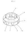
- turbo fan rotor as an example of centrifugal fan rotors.
- the turbo fan rotor has a main plate 1 , a shroud 2 , and a plurality of blades 3, 3 , ... which are disposed between an outer peripheral part 1a of the main plate 1 and the shroud 2 .
- Each blade 3 is shaped like a swept-back wing inclined in a direction opposite to the rotational direction.
- Reference numeral 4 indicates a boss to which a motor rotational shaft is rotatably fastened.
- turbo fan rotor It is difficult to form such a turbo fan rotor as an integral molding of synthetic resin because it has a three-dimensional shape which complicates the drawing-out of a molding.
- a main plate 1 is formed integrally with blades 3, 3 , ..., and leading ends of the blades 3, 3 , ... are welded to an interior surface of a shroud 2 made of synthetic resin.
- a main plate 1 is formed integrally with first half portions of blades 3, 3 , ... while on the other hand a shroud 2 is formed integrally with second half portions of the blades 3, 3 , .... Thereafter, the first half portions and the second half portions are welded together.
- an object of the present invention is to make it possible to manufacture a fan rotor which is inexpensive and rich in recycling efficiency. More specifically, a rotor fan of the present invention is assembled not by a welding means but by an engaging means.
- a first invention is directed to a centrifugal fan rotor comprising a main plate 1 , a shroud 2 , and a plurality of blades 3, 3 , ... disposed between an outer peripheral part 1a of the main plate 1 and the shroud 2 .
- a rotor half-finished product A which is formed as an integral molding of synthetic resin comprising the main plate 1 and the blades 3, 3 , ...
- the shroud 2 which is formed as an integral molding of synthetic resin are manufactured separately.
- an engaging claw is formed integrally with the shroud 2 or with each blade 3 , while on the other hand an engaging part for engaging with the engaging claw is formed in each blade 3 or in the shroud 2 .
- the rotor half-finished product A and the shroud 2 are united together by establishing engagement between the engaging claw and the engaging part.
- a second invention according to the first invention is characterized in that the engaging claw and the engaging part are constructed so that the direction of engagement of the engaging claw and the engaging part becomes a direction in which the force of engagement of the engaging claw and the engaging part increases when a centrifugal force is exerted on each blade 3 .
- a third invention according to the second invention is characterized in that the engaging claw is an inward claw piece 5 which is provided projectingly and formed integrally with an interior surface of the shroud 2 , and is further characterized in that the engaging part is an engaging concave part 6 which is formed in an external surface of each blade 3 .
- a fourth invention according to the second invention is characterized in that the engaging claw is an outward claw piece 9 which is provided projectingly and formed integrally with a leading end of the each blade 3 , and is further characterized in that the engaging part is an engaging hole 10 which is formed in the shroud 2 .
- a fifth invention according to the first invention is characterized in that a rib 8 is formed integrally with a rear surface of the outer peripheral part 1a of the main plate 1.
- a sixth invention is directed to a method of manufacturing a centrifugal fan rotor comprising a main plate 1 , a shroud 2 , and a plurality of blades 3, 3 , ... disposed between an outer peripheral part 1a of the main plate 1 and the shroud 2 .
- a rotor half-finished product A comprising the main plate 1 and the blades 3, 3 , ... is formed as an integral molding of synthetic resin
- the shroud 2 is formed as an integral molding of synthetic resin separately from the rotor half-finished product A .
- an engaging claw which is formed integrally with the shroud 2 or with each blade 3 and an engaging part which is formed in each blade 3 or in the shroud 2 are brought into engagement with each other so that the rotor half-finished product A and the shroud 2 are united together.
- a seventh invention according to the sixth invention is characterized in that the direction of engagement of the engaging claw and the engaging part becomes a direction in which the force of engagement of the engaging claw and the engaging part increases when a centrifugal force is exerted on each blade 3 .
- An eighth invention according to the seventh invention is characterized in that the engaging claw is an inward claw piece 5 provided projectingly and formed integrally with an interior surface of the shroud 2 , and is further characterized in that the engaging part is an engaging concave part 6 formed in an external surface of each blade 3 .
- a ninth invention according to the seventh invention is characterized in that the engaging claw is an outward claw piece 9 provided projectingly and formed integrally with a leading end of the each blade 3 , and is further characterized in that the engaging part is an engaging hole 10 formed in the shroud 2 .
- a tenth invention according to the sixth invention is characterized in that a rib 8 is formed integrally with a rear surface of the outer peripheral part 1a of the main plate 1 at the time of molding of the rotor half-finished product A .
- the engaging claw formed integrally with the shroud 2 or with each blade 3 and the engaging portion formed in each blade 3 or in said shroud 2 are brought into engagement with each other to assemble a fan rotor. Accordingly, it is no longer necessary to employ a conventionally-required welding means. It therefore becomes possible to employ polypropylene which is inexpensive as a material, thereby achieving the reduction in manufacturing costs and the improvement in recycling efficiency.
- the main plate outer peripheral part 1a in the rotor half-finished product A takes the same shape as that of the forming die (i.e., a horizontal shape) at the time immediately after the integral moulding.
- the main plate outer peripheral part 1a is bent slightly toward the side on which the rib 8 is formed (i.e., toward the rear surface).
- the main plate outer peripheral part 1a is deformed in the same direction that the blade 3 is deformed by centrifugal force. Accordingly, if assembled to the shroud 2 immediately after the integral moulding of the rotor half-finished product A , this facilitates assembly work. Furthermore, the force of engagement increases after the assembly work. As a result, assembly workability is improved and, in addition, the engagement will not come loose during the operation.
- a centrifugal fan rotor comprising a main plate 1 , a shroud 2 , and a plurality of blades 3, 3 , ... disposed between an outer peripheral part 1a of the main plate 1 and the shroud 2
- a rotor half-finished product A composed of the main plate 1 and the blades 3, 3, ... is formed as an integral molding of synthetic resin and the shroud 2 is formed as an integral molding of synthetic resin separately from the rotor half-finished product A .
- an engaging claw integrally formed with the shroud 2 or with each blade 3 and an engaging part integrally formed with each blade 3 or with the shroud 2 are engaged with each other so that the rotor half-finished product A and the shroud 2 are united together. Accordingly, in accordance with these inventions, it is no longer necessary to employ a conventionally-required welding means. It therefore becomes possible to employ polypropylene which is inexpensive as a material, thereby achieving the reduction in manufacturing costs and the improvement in recycling efficiency.
- the second and seventh inventions it is arranged such that the direction of engagement of the engaging claw and the engaging part becomes a direction in which the force of engagement of the engaging claw and the engaging part increases when a centrifugal force is exerted on the blades 3, 3, .... Accordingly, in accordance with these inventions, even when a centrifugal force acts on the blade 3 during the operation, the engagement between the engaging claw and the engaging part will not come loose. As the result of this, durability is improved significantly and no chatter sound is produced in the engaging part during the operation.
- the engaging claw is an inward claw piece 5 provided in a projecting manner and formed integrally with an interior surface of the shroud 2
- the engaging part is an engaging concave part 6 formed in an external surface of each blade 3 .
- the engaging claw is an outward claw piece 9 provided in a projecting manner and formed integrally with a leading end of the each blade 3 , and that the engaging part is an engaging hole 10 formed in the shroud 2 . Accordingly, in accordance with these inventions, it is possible to firmly unite together each blade 3 and the shroud 2 by a simple means such as the engaging of the claw piece 9 and the engaging hole 10 .
- the main plate outer peripheral part 1a in the rotor half-finished product A takes the same shape as that of the forming die (i.e., a horizontal shape) at the time immediately after the integral moulding; however, after being cooled, the main plate outer peripheral part 1a is bent slightly toward the side on which the rib 8 is formed (i.e., toward the rear surface).
- the main plate outer peripheral part 1a is deformed in the same direction that the blade 3 is deformed by centrifugal force. Accordingly, if assembled to the shroud 2 immediately after the integral moulding of the rotor half-finished product A , this facilitates assembly work. As the result of this, the force of engagement increases after the assembly work. Consequently, assembly workability is improved and, in addition, the engagement will not come loose during the operation.
- a centrifugal fan rotor (i.e., a turbo fan rotor) which is manufactured in accordance with each of the embodiments is similar in structure to the one previously described in terms of the Background Art (see Figure 1 ).
- This turbo fan rotor comprises a main plate 1, a shroud 2, and a plurality of blades 3, 3, ... installed between an outer peripheral part 1a of the main plate 1 and the shroud 2 .
- Each blade 3 is shaped like a swept-back wing which is inclined in a direction opposite to the rotational direction.
- Reference numeral 4 indicates a boss to which a motor rotational shaft is rotatably fastened.
- FIG. 2 and 4 there is shown a centrifugal fan rotor according to a first embodiment of the present invention.
- an inward claw piece 5 serving as an engaging claw is formed, in a projecting manner, integrally with an internal surface of the shroud 2 .
- an engaging concave part 6 serving as an engaging part is formed on the side of an external surface of each blade 3 .
- Reference numeral 7 indicates a cavity for use in integral molding of the claw piece 5 at the time of moulding of the shroud 2 .
- the turbo fan rotor of the present embodiment is manufactured as follows.
- a rotor half-finished product A comprising a main plate 1 and blades 3, 3 , ... is formed as an integral molding of synthetic resin (for example, polypropylene).
- a shroud 2 is formed as an integral molding of synthetic resin (for example, polypropylene).
- the claw piece 5 of the shroud 2 is engaged into an engaging concave part 6 of the blade 3 so that the rotor half-finished product A and the shroud 2 are united together integrally.
- the shroud 2 and the blade 3 are united together by engagement between the inward claw piece 5 and the engaging concave part 6 formed in the outer peripheral surface of the blade 3 .
- the direction of engagement of the claw piece 5 and the engagement concave part 6 becomes a direction in which the force of engagement increases when a centrifugal force acts on the blade 3 .
- Ribs 8, 8 , ... are formed integrally with a rear surface of the outer peripheral part 1a of the main plate 1 at the time of moulding of the rotor half-finished product A in the present embodiment. Because of the provision of the ribs 8, 8 , ..., the main plate outer peripheral part 1a becomes warped in the direction of the rear surface at the time of cooling after the molding. In other words, during the cooling, the surface of each rib 8 is first solidified when cooled and then is shrunk. As a result, the main plate outer peripheral part 1a becomes warped in the direction of the rear surface on which the ribs 8, 8 , ... are formed. As shown in Figure 4 , the ribs 8, 8 , ... are shaped like a mound and are arranged radially, circumferentially, and in a direction of interconnecting them.
- the main plate outer peripheral part 1a in the rotor half-finished product A takes the same shape as that of its forming die (i.e., a horizontal shape) immediately after the integral moulding, as indicated by chain double-dashed line of Figure 3; however, after being cooled the main plate outer peripheral part 1a becomes warped slightly in the direction of the side on which the ribs 8, 8, ... are formed (i.e., in the direction of the rear surface) as indicated by solid line of Figure 3 .
- the main plate outer peripheral part 1a deforms in the same direction that the blades 3, 3 , ... deform by centrifugal force.
- FIG. 5 there is shown a centrifugal fan rotor according to a second embodiment of the present invention.
- an outward claw piece 9 serving as an engaging claw is provided projectingly and formed integrally with an leading end of the blade 3 .
- the shroud 2 is provided with an engaging hole 10 serving as an engaging part. And, by engaging the claw piece 9 into the engaging hole 10 , the blade 3 and the shroud 2 are united together.
- This turbo fan rotor is manufactured as follows.
- a rotor half-finished product A comprising a main plate 1 and a plurality of blades 3, 3 , ... is formed as an integral molding of synthetic resin (for example, polypropylene), together with a claw piece 9 .
- a shroud 2 is formed as an integral molding of synthetic resin (for example, polypropylene).
- the claw piece 9 of the blade 3 is engaged into the engaging hole 10 of the shroud 2 , whereby the rotor half-finished product A and the shroud 2 are united together integrally.
- the rotor half-finished product A and the shroud 2 are united together by engagement of the outward claw piece 9 into the engaging hole 10 formed in the shroud 2 .
- the direction of engagement of the claw piece 9 and the engaging hole 10 becomes a direction in which the force of engagement increases when a centrifugal force acts on the blade 3 .
- ribs 8, 8 , ... are formed integrally with the rear surface of the outer peripheral part 1a of the main plate 1 at the time of molding of the rotor half-finished product A , as in the first embodiment. Accordingly, the same working effects as the first embodiment are obtained.
- the present invention is applicable to centrifugal fan rotors other than the turbo fan rotor.
- the present invention provides a centrifugal fan rotor and a method of manufacturing a centrifugal fan rotor useful for manufacture of turbo fan rotors and especially suitable for molding of turbo fan rotors from synthetic resin.
Landscapes
- Engineering & Computer Science (AREA)
- Mechanical Engineering (AREA)
- General Engineering & Computer Science (AREA)
- Structures Of Non-Positive Displacement Pumps (AREA)
Abstract
In a method of manufacturing a centrifugal fan rotor comprising a main plate (1), a
shroud (2), and a plurality of blades (3, 3, ...) disposed between an outer peripheral part
(1a) of the main plate (1) and the shroud (2), a rotor half-finished product (A) comprising
the main plate (1) and the blades (3, 3, ...) is formed as an integral molding of synthetic
resin and, in addition, the shroud (2) is formed as an integral molding of synthetic resin
separately from the rotor half-finished product (A). Thereafter, an engaging claw (5)
formed integrally with the shroud (2) is engaged into an engaging part (6) formed in each
blade (3) so that the rotor half-finished product (A) and the shroud (2) are united together.
As a result, it becomes possible to use inexpensive polypropylene as a material and the
reduction in manufacturing costs and the improvement in recycling efficiency are achieved,
without having to employ a conventionally-used welding means.
Description
The present invention relates to a centrifugal fan rotor and to a manufacturing
method thereof.
Referring to Figure 1, there is illustrated a turbo fan rotor as an example of
centrifugal fan rotors. The turbo fan rotor has a main plate 1, a shroud 2, and a plurality of
blades 3, 3, ... which are disposed between an outer peripheral part 1a of the main plate 1
and the shroud 2. Each blade 3 is shaped like a swept-back wing inclined in a direction
opposite to the rotational direction. Reference numeral 4 indicates a boss to which a motor
rotational shaft is rotatably fastened.
It is difficult to form such a turbo fan rotor as an integral molding of synthetic resin
because it has a three-dimensional shape which complicates the drawing-out of a molding.
With a view to coping with this difficulty, the following conventional techniques
have been proposed. For example, there is a technique known in the art in which a main
plate 1 is formed integrally with blades 3, 3, ..., and leading ends of the blades 3, 3, ... are
welded to an interior surface of a shroud 2 made of synthetic resin. In addition, there is
another conventional technique in which a main plate 1 is formed integrally with first half
portions of blades 3, 3, ... while on the other hand a shroud 2 is formed integrally with
second half portions of the blades 3, 3, .... Thereafter, the first half portions and the
second half portions are welded together.
The above-described conventional techniques, however, require a welding process
step of a higher level of accuracy, therefore producing a problem of increased
manufacturing costs.
In addition, there is another problem that polypropylene (PP), which does not suit
for welding but has advantages of being inexpensive and recycle-friendly, cannot be used
as a material.
Furthermore, there is the possibility that during the operation centrifugal forces
cause a welded junction to come loose if deteriorated with age.
Bearing in mind the above-described drawbacks, the present invention was made.
Accordingly, an object of the present invention is to make it possible to manufacture a fan
rotor which is inexpensive and rich in recycling efficiency. More specifically, a rotor fan
of the present invention is assembled not by a welding means but by an engaging means.
A first invention is directed to a centrifugal fan rotor comprising a main plate 1, a
shroud 2, and a plurality of blades 3, 3, ... disposed between an outer peripheral part 1a of
the main plate 1 and the shroud 2. And, a rotor half-finished product A which is formed as
an integral molding of synthetic resin comprising the main plate 1 and the blades 3, 3, ...,
and the shroud 2 which is formed as an integral molding of synthetic resin are
manufactured separately. Furthermore, an engaging claw is formed integrally with the
shroud 2 or with each blade 3, while on the other hand an engaging part for engaging with
the engaging claw is formed in each blade 3 or in the shroud 2. In addition, the rotor half-finished
product A and the shroud 2 are united together by establishing engagement
between the engaging claw and the engaging part.
A second invention according to the first invention is characterized in that the
engaging claw and the engaging part are constructed so that the direction of engagement of
the engaging claw and the engaging part becomes a direction in which the force of
engagement of the engaging claw and the engaging part increases when a centrifugal force
is exerted on each blade 3.
A third invention according to the second invention is characterized in that the
engaging claw is an inward claw piece 5 which is provided projectingly and formed
integrally with an interior surface of the shroud 2, and is further characterized in that the
engaging part is an engaging concave part 6 which is formed in an external surface of each
blade 3.
A fourth invention according to the second invention is characterized in that the
engaging claw is an outward claw piece 9 which is provided projectingly and formed
integrally with a leading end of the each blade 3, and is further characterized in that the
engaging part is an engaging hole 10 which is formed in the shroud 2.
A fifth invention according to the first invention is characterized in that a rib 8 is
formed integrally with a rear surface of the outer peripheral part 1a of the main plate 1.
A sixth invention is directed to a method of manufacturing a centrifugal fan rotor
comprising a main plate 1, a shroud 2, and a plurality of blades 3, 3, ... disposed between
an outer peripheral part 1a of the main plate 1 and the shroud 2. And, a rotor half-finished
product A comprising the main plate 1 and the blades 3, 3, ... is formed as an integral
molding of synthetic resin, and the shroud 2 is formed as an integral molding of synthetic
resin separately from the rotor half-finished product A. Thereafter, an engaging claw
which is formed integrally with the shroud 2 or with each blade 3 and an engaging part
which is formed in each blade 3 or in the shroud 2 are brought into engagement with each
other so that the rotor half-finished product A and the shroud 2 are united together.
A seventh invention according to the sixth invention is characterized in that the
direction of engagement of the engaging claw and the engaging part becomes a direction in
which the force of engagement of the engaging claw and the engaging part increases when
a centrifugal force is exerted on each blade 3.
An eighth invention according to the seventh invention is characterized in that the
engaging claw is an inward claw piece 5 provided projectingly and formed integrally with
an interior surface of the shroud 2, and is further characterized in that the engaging part is
an engaging concave part 6 formed in an external surface of each blade 3.
A ninth invention according to the seventh invention is characterized in that the
engaging claw is an outward claw piece 9 provided projectingly and formed integrally with
a leading end of the each blade 3, and is further characterized in that the engaging part is
an engaging hole 10 formed in the shroud 2.
Finally, a tenth invention according to the sixth invention is characterized in that a
rib 8 is formed integrally with a rear surface of the outer peripheral part 1a of the main
plate 1 at the time of molding of the rotor half-finished product A.
In the first and sixth inventions, after integral molding of the rotor half-finished
product A made up of the main plate 1 and the blades 3, 3, ... by the use of a synthetic
resin, the engaging claw formed integrally with the shroud 2 or with each blade 3 and the
engaging portion formed in each blade 3 or in said shroud 2 are brought into engagement
with each other to assemble a fan rotor. Accordingly, it is no longer necessary to employ a
conventionally-required welding means. It therefore becomes possible to employ
polypropylene which is inexpensive as a material, thereby achieving the reduction in
manufacturing costs and the improvement in recycling efficiency.
In the second and seventh inventions, even when a centrifugal force acts on the
blade 3 during the operation, the engagement between the engaging claw and the engaging
part will not come loose. As the result of this, durability is improved significantly and no
chatter sound is produced in the engaging part during the operation.
In the third and eighth inventions, it is possible to firmly unite together each blade 3
and the shroud 2 by a simple means such as the engaging of the claw piece 5 and the
engaging concave part 6.
In the fourth and ninth inventions, it is possible to firmly unite together each blade
3 and the shroud 2 by a simple means such as the engaging of the claw piece 9 and the
engaging hole 10.
In the fifth and tenth inventions, the main plate outer peripheral part 1a in the rotor
half-finished product A takes the same shape as that of the forming die (i.e., a horizontal
shape) at the time immediately after the integral moulding. After being cooled, the main
plate outer peripheral part 1a is bent slightly toward the side on which the rib 8 is formed
(i.e., toward the rear surface). In other words, the main plate outer peripheral part 1a is
deformed in the same direction that the blade 3 is deformed by centrifugal force.
Accordingly, if assembled to the shroud 2 immediately after the integral moulding of the
rotor half-finished product A, this facilitates assembly work. Furthermore, the force of
engagement increases after the assembly work. As a result, assembly workability is
improved and, in addition, the engagement will not come loose during the operation.
In the first and sixth inventions, in manufacturing a centrifugal fan rotor comprising
a main plate 1, a shroud 2, and a plurality of blades 3, 3, ... disposed between an outer
peripheral part 1a of the main plate 1 and the shroud 2, a rotor half-finished product A
composed of the main plate 1 and the blades 3, 3, ... is formed as an integral molding of
synthetic resin and the shroud 2 is formed as an integral molding of synthetic resin
separately from the rotor half-finished product A. And, an engaging claw integrally
formed with the shroud 2 or with each blade 3 and an engaging part integrally formed with
each blade 3 or with the shroud 2 are engaged with each other so that the rotor half-finished
product A and the shroud 2 are united together. Accordingly, in accordance with
these inventions, it is no longer necessary to employ a conventionally-required welding
means. It therefore becomes possible to employ polypropylene which is inexpensive as a
material, thereby achieving the reduction in manufacturing costs and the improvement in
recycling efficiency.
In the second and seventh inventions, it is arranged such that the direction of
engagement of the engaging claw and the engaging part becomes a direction in which the
force of engagement of the engaging claw and the engaging part increases when a
centrifugal force is exerted on the blades 3, 3, .... Accordingly, in accordance with these
inventions, even when a centrifugal force acts on the blade 3 during the operation, the
engagement between the engaging claw and the engaging part will not come loose. As the
result of this, durability is improved significantly and no chatter sound is produced in the
engaging part during the operation.
In the third and eighth inventions, it is arranged such that the engaging claw is an
inward claw piece 5 provided in a projecting manner and formed integrally with an interior
surface of the shroud 2, and that the engaging part is an engaging concave part 6 formed in
an external surface of each blade 3. Accordingly, in accordance with these inventions, it is
possible to firmly unite together each blade 3 and the shroud 2 by a simple means such as
the engaging of the claw piece 5 and the engaging concave part 6.
In the fourth and ninth inventions, it is arranged such that the engaging claw is an
outward claw piece 9 provided in a projecting manner and formed integrally with a leading
end of the each blade 3, and that the engaging part is an engaging hole 10 formed in the
shroud 2. Accordingly, in accordance with these inventions, it is possible to firmly unite
together each blade 3 and the shroud 2 by a simple means such as the engaging of the claw
piece 9 and the engaging hole 10.
Finally, in the fifth and tenth inventions, it is arranged such that a rib 8 is formed
integrally with a rear surface of the outer peripheral part 1a of the main plate 1 at the time
of molding of the rotor half-finished product A. Accordingly, in accordance with these
inventions, the main plate outer peripheral part 1a in the rotor half-finished product A
takes the same shape as that of the forming die (i.e., a horizontal shape) at the time
immediately after the integral moulding; however, after being cooled, the main plate outer
peripheral part 1a is bent slightly toward the side on which the rib 8 is formed (i.e., toward
the rear surface). In other words, the main plate outer peripheral part 1a is deformed in the
same direction that the blade 3 is deformed by centrifugal force. Accordingly, if
assembled to the shroud 2 immediately after the integral moulding of the rotor half-finished
product A, this facilitates assembly work. As the result of this, the force of
engagement increases after the assembly work. Consequently, assembly workability is
improved and, in addition, the engagement will not come loose during the operation.
Hereinbelow, several preferred embodiments of the present invention will be
described in detail with reference to the accompanying drawings.
A centrifugal fan rotor (i.e., a turbo fan rotor) which is manufactured in accordance
with each of the embodiments is similar in structure to the one previously described in
terms of the Background Art (see Figure 1). This turbo fan rotor comprises a main plate 1,
a shroud 2, and a plurality of blades 3, 3, ... installed between an outer peripheral part 1a
of the main plate 1 and the shroud 2. Each blade 3 is shaped like a swept-back wing which
is inclined in a direction opposite to the rotational direction. Reference numeral 4 indicates
a boss to which a motor rotational shaft is rotatably fastened.
Referring to Figures 2 and 4, there is shown a centrifugal fan rotor according to a
first embodiment of the present invention.
In the centrifugal fan rotor (i.e., the turbo fan rotor), as shown in Figure 2, an
inward claw piece 5 serving as an engaging claw is formed, in a projecting manner,
integrally with an internal surface of the shroud 2. On the other hand, an engaging concave
part 6 serving as an engaging part is formed on the side of an external surface of each blade
3. And, by bringing the claw piece 5 into engagement with the engaging concave parts 6,
each blade 3 and the shroud 2 are united together. Reference numeral 7 indicates a cavity
for use in integral molding of the claw piece 5 at the time of moulding of the shroud 2.
The turbo fan rotor of the present embodiment is manufactured as follows. In the
first place, a rotor half-finished product A comprising a main plate 1 and blades 3, 3, ... is
formed as an integral molding of synthetic resin (for example, polypropylene). On the
other hand, together with a claw piece 5, a shroud 2 is formed as an integral molding of
synthetic resin (for example, polypropylene). Thereafter, the claw piece 5 of the shroud 2
is engaged into an engaging concave part 6 of the blade 3 so that the rotor half-finished
product A and the shroud 2 are united together integrally.
As a result of such arrangement, the blade 3 and the shroud 2 are firmly united
together by a simple means such as engagement of the claw piece 5 and the engaging
concave part 6. Accordingly, unlike the conventional techniques, it is no longer necessary
to use a welding means.
Consequently, it becomes possible to use inexpensive polypropylene as a material
and the reduction in manufacturing costs and the improvement in recycling efficiency are
achieved.
Besides, the shroud 2 and the blade 3 are united together by engagement between
the inward claw piece 5 and the engaging concave part 6 formed in the outer peripheral
surface of the blade 3. As the result of this, the direction of engagement of the claw piece
5 and the engagement concave part 6 becomes a direction in which the force of
engagement increases when a centrifugal force acts on the blade 3.
Accordingly, even when a centrifugal force is exerted on the blade 3 during
operation, the engagement between the claw piece 5 and the engaging concave part 6 will
not come loose. As the result of this, durability is improved significantly and no chatter
sound is produced in the engaging part during operation.
As a result of such arrangement, the main plate outer peripheral part 1a in the rotor
half-finished product A takes the same shape as that of its forming die (i.e., a horizontal
shape) immediately after the integral moulding, as indicated by chain double-dashed line
of Figure 3; however, after being cooled the main plate outer peripheral part 1a becomes
warped slightly in the direction of the side on which the ribs 8, 8, ... are formed (i.e., in the
direction of the rear surface) as indicated by solid line of Figure 3. In other words, the
main plate outer peripheral part 1a deforms in the same direction that the blades 3, 3, ...
deform by centrifugal force. Accordingly, if assembled to the shroud 2 immediately after
integral moulding of the rotor half-finished product A, this facilitates assembly work and
the force of engagement increases after the assembly work. As a result, assembly
workability is improved and, in addition, the engagement will not come loose.
Referring to Figure 5, there is shown a centrifugal fan rotor according to a second
embodiment of the present invention.
In the centrifugal fan rotor (i.e., the turbo fan rotor) of the present embodiment, an
outward claw piece 9 serving as an engaging claw is provided projectingly and formed
integrally with an leading end of the blade 3. On the other hand, the shroud 2 is provided
with an engaging hole 10 serving as an engaging part. And, by engaging the claw piece 9
into the engaging hole 10, the blade 3 and the shroud 2 are united together.
This turbo fan rotor is manufactured as follows. In the first place, a rotor half-finished
product A comprising a main plate 1 and a plurality of blades 3, 3, ... is formed as
an integral molding of synthetic resin (for example, polypropylene), together with a claw
piece 9. On the other hand, a shroud 2 is formed as an integral molding of synthetic resin
(for example, polypropylene). Thereafter, the claw piece 9 of the blade 3 is engaged into
the engaging hole 10 of the shroud 2, whereby the rotor half-finished product A and the
shroud 2 are united together integrally.
As a result of such arrangement, the blade 3 and the shroud 2 are firmly joined
together by a simple means such as engagement of the claw piece 9 into the engaging hole
10. Accordingly, unlike the conventional techniques, it is no longer necessary to use a
welding means.
Consequently, it becomes possible to use inexpensive polypropylene as a material
and the reduction in manufacturing costs and the improvement in recycling efficiency are
achieved.
Besides, the rotor half-finished product A and the shroud 2 are united together by
engagement of the outward claw piece 9 into the engaging hole 10 formed in the shroud 2.
As the result of this, the direction of engagement of the claw piece 9 and the engaging hole
10 becomes a direction in which the force of engagement increases when a centrifugal
force acts on the blade 3.
Accordingly, even when centrifugal forces act on the blade 3 during operation, the
engagement between the claw piece 9 and the engaging hole 10 will not come loose. As
the result of this, durability is improved significantly and no chatter sound is produced in
the engaging part during operation.
In addition, also in the case of the present embodiment, ribs 8, 8, ... are formed
integrally with the rear surface of the outer peripheral part 1a of the main plate 1 at the
time of molding of the rotor half-finished product A, as in the first embodiment.
Accordingly, the same working effects as the first embodiment are obtained.
It is needless to say that the present invention is applicable to centrifugal fan rotors
other than the turbo fan rotor.
As has been described above, the present invention provides a centrifugal fan rotor
and a method of manufacturing a centrifugal fan rotor useful for manufacture of turbo fan
rotors and especially suitable for molding of turbo fan rotors from synthetic resin.
Claims (10)
- A centrifugal fan rotor comprising a main plate (1), a shroud (2), and a plurality of blades (3, 3, ...) disposed between an outer peripheral part (1a) of said main plate (1) and said shroud (2),
wherein a rotor half-finished product (A) formed as an integral molding of synthetic resin comprising said main plate (1) and said blades (3, 3, ...), and said shroud (2) formed as an integral molding of synthetic resin are manufactured separately,
wherein an engaging claw is formed integrally with said shroud (2) or with each said blade (3), and wherein an engaging part for engaging with said engaging claw is formed in each said blade (3) or in said shroud (2), and
wherein said rotor half-finished product (A) and said shroud (2) are united together by establishing engagement between said engaging claw and said engaging part. - The centrifugal fan rotor of claim 1, wherein said engaging claw and said engaging part are constructed so that the direction of engagement of said engaging claw and said engaging part becomes a direction in which the force of engagement of said engaging claw and said engaging part increases when a centrifugal force is exerted on each said blade (3).
- The centrifugal fan rotor of claim 2,
wherein said engaging claw is an inward claw piece (5) provided projectingly and formed integrally with an interior surface of said shroud (2),
wherein said engaging part is an engaging concave part (6) formed in an external surface of each said blade (3). - The centrifugal fan rotor of claim 2,
wherein said engaging claw is an outward claw piece (9) provided projectingly and formed integrally with a leading end of said each blade (3),
wherein said engaging part is an engaging hole (10) formed in said shroud (2). - The centrifugal fan rotor of claim 1,
wherein a rib (8) is formed integrally with a rear surface of said outer peripheral part (1a) of said main plate (1). - A method of manufacturing a centrifugal fan rotor comprising a main plate (1), a shroud (2), and a plurality of blades (3, 3, ...) disposed between an outer peripheral part (1a) of said main plate (1) and said shroud (2), said method comprising the steps of:providing a rotor half-finished product (A) formed as an integral molding of synthetic resin comprising said main plate (1) and said blades (3, 3, ...), and providing said shroud (2) formed as an integral molding of synthetic resin separately from said rotor half-finished product (A),establishing engagement between an engaging claw which is formed integrally with said shroud (2) or with each said blade (3) and an engaging part which is formed in each said blade (3) or in said shroud (2) so that said rotor half-finished product (A) and said shroud (2) are united together.
- The centrifugal fan rotor manufacturing method of claim 6, wherein the direction of engagement of said engaging claw and said engaging part becomes a direction in which the force of engagement of said engaging claw and said engaging part increases when a centrifugal force is exerted on each said blade (3).
- The centrifugal fan rotor manufacturing method of claim 7, wherein said engaging claw is an inward claw piece (5) provided projectingly and formed integrally with an interior surface of said shroud (2), and wherein said engaging part is an engaging concave part (6) formed in an external surface of each said blade (3).
- The centrifugal fan rotor manufacturing method of claim 7, wherein said engaging claw is an outward claw piece (9) provided projectingly and formed integrally with a leading end of said each blade (3), and wherein said engaging part is an engaging hole (10) formed in said shroud (2).
- The centrifugal fan rotor manufacturing method of claim 6, wherein a rib (8) is formed integrally with a rear surface of said outer peripheral part (1a) of said main plate (1) at the time of molding of said rotor half-finished product (A).
Applications Claiming Priority (3)
| Application Number | Priority Date | Filing Date | Title |
|---|---|---|---|
| JP2002101078 | 2002-04-03 | ||
| JP2002101078 | 2002-04-03 | ||
| PCT/JP2003/004244 WO2003087582A1 (en) | 2002-04-03 | 2003-04-02 | Centrifugal fan rotor and method of manufacturing the fan rotor |
Publications (2)
| Publication Number | Publication Date |
|---|---|
| EP1496265A1 true EP1496265A1 (en) | 2005-01-12 |
| EP1496265A4 EP1496265A4 (en) | 2010-12-01 |
Family
ID=29241637
Family Applications (1)
| Application Number | Title | Priority Date | Filing Date |
|---|---|---|---|
| EP03715745A Withdrawn EP1496265A4 (en) | 2002-04-03 | 2003-04-02 | CENTRIFUGAL BLOWER ENGINE AND METHOD FOR PRODUCING THE BLOWER MOTOR |
Country Status (5)
| Country | Link |
|---|---|
| EP (1) | EP1496265A4 (en) |
| JP (1) | JP3589243B2 (en) |
| CN (1) | CN100582491C (en) |
| AU (1) | AU2003220845B2 (en) |
| WO (1) | WO2003087582A1 (en) |
Cited By (2)
| Publication number | Priority date | Publication date | Assignee | Title |
|---|---|---|---|---|
| CN101839255A (en) * | 2009-03-13 | 2010-09-22 | 日本电产株式会社 | Centrifugal fan |
| ES2378207A1 (en) * | 2007-03-14 | 2012-04-10 | Mitsubishi Electric Corporation | CENTRIFUGAL FAN AIR CONDITIONER. |
Families Citing this family (4)
| Publication number | Priority date | Publication date | Assignee | Title |
|---|---|---|---|---|
| WO2007040236A1 (en) * | 2005-10-06 | 2007-04-12 | Mitsubishi Electric Corporation | Turbo fan and air conditioner |
| JP2007163026A (en) * | 2005-12-14 | 2007-06-28 | Hitachi Ltd | Indoor unit for air conditioner and air conditioner |
| DE102009028130A1 (en) * | 2009-07-30 | 2011-02-03 | Robert Bosch Gmbh | Guide geometry for semi-axial fan wheels |
| CN106640751A (en) * | 2016-11-14 | 2017-05-10 | 无锡市乾泰金属构件厂 | High-stability fan impeller |
Family Cites Families (9)
| Publication number | Priority date | Publication date | Assignee | Title |
|---|---|---|---|---|
| US2962207A (en) * | 1957-08-23 | 1960-11-29 | Robert A Mayne | Blower wheel |
| GB1171961A (en) * | 1966-02-24 | 1969-11-26 | Smiths Industries Ltd | Improvements in or relating to Centrifugal Fans |
| JPS4719776Y1 (en) * | 1968-05-15 | 1972-07-05 | ||
| US3811978A (en) * | 1972-08-21 | 1974-05-21 | Brookside Corp | Method of forming centrifugal blower wheel |
| JPS5366007A (en) * | 1976-11-26 | 1978-06-13 | Hitachi Ltd | Method of manufacturing runner of centrifugal blower |
| JPS56169497U (en) | 1980-05-20 | 1981-12-15 | ||
| JPH02131099U (en) * | 1989-04-05 | 1990-10-30 | ||
| JPH07247998A (en) * | 1994-03-11 | 1995-09-26 | Fujitsu General Ltd | Cross flow fan |
| KR100369919B1 (en) * | 1999-03-03 | 2003-01-29 | 미쓰비시덴키 가부시키가이샤 | Fan, a method of molding molden metal for fan, and a device or molding molden metal for fan |
-
2003
- 2003-04-02 EP EP03715745A patent/EP1496265A4/en not_active Withdrawn
- 2003-04-02 JP JP2003584502A patent/JP3589243B2/en not_active Expired - Fee Related
- 2003-04-02 AU AU2003220845A patent/AU2003220845B2/en not_active Ceased
- 2003-04-02 WO PCT/JP2003/004244 patent/WO2003087582A1/en not_active Ceased
- 2003-04-02 CN CN03807898A patent/CN100582491C/en not_active Expired - Fee Related
Cited By (3)
| Publication number | Priority date | Publication date | Assignee | Title |
|---|---|---|---|---|
| ES2378207A1 (en) * | 2007-03-14 | 2012-04-10 | Mitsubishi Electric Corporation | CENTRIFUGAL FAN AIR CONDITIONER. |
| CN101839255A (en) * | 2009-03-13 | 2010-09-22 | 日本电产株式会社 | Centrifugal fan |
| CN101839255B (en) * | 2009-03-13 | 2013-01-02 | 日本电产株式会社 | Centrifugal fan |
Also Published As
| Publication number | Publication date |
|---|---|
| CN1646814A (en) | 2005-07-27 |
| WO2003087582A1 (en) | 2003-10-23 |
| AU2003220845B2 (en) | 2007-08-09 |
| CN100582491C (en) | 2010-01-20 |
| JPWO2003087582A1 (en) | 2005-08-18 |
| EP1496265A4 (en) | 2010-12-01 |
| JP3589243B2 (en) | 2004-11-17 |
| AU2003220845A1 (en) | 2003-10-27 |
Similar Documents
| Publication | Publication Date | Title |
|---|---|---|
| US8030808B2 (en) | Rotor for a direct current drive motor and a method for producing the same | |
| JP2003065291A (en) | Turbofan and its manufacturing mold | |
| US9416792B2 (en) | Electrical machine having a fan wheel | |
| CN100404877C (en) | Turbo blower and its manufacturing mold | |
| JP3934264B2 (en) | Commutator, motor provided with commutator, commutator piece, and commutator forming method | |
| AU2003220845B2 (en) | Centrifugal fan rotor and manufacturing method thereof. | |
| KR20040104971A (en) | Turbofan and manufacturing method thereof | |
| JPH084875A (en) | Torque converter stator structure | |
| US5476366A (en) | Fan construction and method of assembly | |
| EP0500442B1 (en) | Fan rotor for rotating electric machines, particularly for alternators for cars | |
| EP1416164A2 (en) | Two-piece molded fan | |
| US8128370B2 (en) | Blade structure for torque converter and process of producing the same | |
| JPH094598A (en) | Method of manufacturing impeller for centrifugal blower having airfoil blades | |
| JPH07127597A (en) | Impeller for electric blower | |
| CN100359184C (en) | Belt ring fan and method of manufacturing the same | |
| WO2006062185A1 (en) | Method of producing axial-flow fan and axial-flow fan | |
| JPH116556A (en) | Impeller, blade member for impeller, and method of manufacturing the same | |
| JP3843883B2 (en) | Blower and blower cap manufacturing method | |
| JPH0674195A (en) | Centrifugal fan and manufacturing method thereof | |
| JPS626318Y2 (en) | ||
| US20060222498A1 (en) | Impeller for centrifugal blower | |
| JP3832442B2 (en) | Blower and manufacturing method thereof | |
| KR100688081B1 (en) | Joining structure of pulley and rotating shaft and its method | |
| JP4695687B2 (en) | Impeller, fan device, and impeller manufacturing method | |
| JP3810672B2 (en) | Impeller of vortex blower and manufacturing method thereof |
Legal Events
| Date | Code | Title | Description |
|---|---|---|---|
| PUAI | Public reference made under article 153(3) epc to a published international application that has entered the european phase |
Free format text: ORIGINAL CODE: 0009012 |
|
| 17P | Request for examination filed |
Effective date: 20041020 |
|
| AK | Designated contracting states |
Kind code of ref document: A1 Designated state(s): AT BE BG CH CY CZ DE DK EE ES FI FR GB GR HU IE IT LI LU MC NL PT RO SE SI SK TR |
|
| AX | Request for extension of the european patent |
Extension state: AL LT LV MK |
|
| A4 | Supplementary search report drawn up and despatched |
Effective date: 20101102 |
|
| 17Q | First examination report despatched |
Effective date: 20110405 |
|
| STAA | Information on the status of an ep patent application or granted ep patent |
Free format text: STATUS: THE APPLICATION IS DEEMED TO BE WITHDRAWN |
|
| 18D | Application deemed to be withdrawn |
Effective date: 20111018 |