EP1496246A1 - Injection nozzle - Google Patents
Injection nozzle Download PDFInfo
- Publication number
- EP1496246A1 EP1496246A1 EP04251360A EP04251360A EP1496246A1 EP 1496246 A1 EP1496246 A1 EP 1496246A1 EP 04251360 A EP04251360 A EP 04251360A EP 04251360 A EP04251360 A EP 04251360A EP 1496246 A1 EP1496246 A1 EP 1496246A1
- Authority
- EP
- European Patent Office
- Prior art keywords
- injection nozzle
- valve needle
- annular groove
- seating
- fuel
- Prior art date
- Legal status (The legal status is an assumption and is not a legal conclusion. Google has not performed a legal analysis and makes no representation as to the accuracy of the status listed.)
- Ceased
Links
Images


Classifications
-
- F—MECHANICAL ENGINEERING; LIGHTING; HEATING; WEAPONS; BLASTING
- F02—COMBUSTION ENGINES; HOT-GAS OR COMBUSTION-PRODUCT ENGINE PLANTS
- F02M—SUPPLYING COMBUSTION ENGINES IN GENERAL WITH COMBUSTIBLE MIXTURES OR CONSTITUENTS THEREOF
- F02M61/00—Fuel-injectors not provided for in groups F02M39/00 - F02M57/00 or F02M67/00
- F02M61/16—Details not provided for in, or of interest apart from, the apparatus of groups F02M61/02 - F02M61/14
- F02M61/18—Injection nozzles, e.g. having valve seats; Details of valve member seated ends, not otherwise provided for
- F02M61/1873—Valve seats or member ends having circumferential grooves or ridges, e.g. toroidal
-
- F—MECHANICAL ENGINEERING; LIGHTING; HEATING; WEAPONS; BLASTING
- F02—COMBUSTION ENGINES; HOT-GAS OR COMBUSTION-PRODUCT ENGINE PLANTS
- F02M—SUPPLYING COMBUSTION ENGINES IN GENERAL WITH COMBUSTIBLE MIXTURES OR CONSTITUENTS THEREOF
- F02M61/00—Fuel-injectors not provided for in groups F02M39/00 - F02M57/00 or F02M67/00
- F02M61/04—Fuel-injectors not provided for in groups F02M39/00 - F02M57/00 or F02M67/00 having valves, e.g. having a plurality of valves in series
- F02M61/042—The valves being provided with fuel passages
Definitions
- the invention relates to an injection nozzle for use in a fuel injection system for an internal combustion engine. It relates particularly, but not exclusively, to an injection nozzle for use in a compression ignition internal combustion engine, in which a valve needle is engageable with a seating surface to control the injection of fuel to an associated combustion space through one or more nozzle outlets.
- a valve needle 10 has a seating surface 28, or seating "line", which engages with a seat 12 defined by a nozzle body bore 14 within which the valve needle 10 moves.
- injection nozzle outlets 16 are opened to enable high pressure fuel to be injected into the associated engine cylinder (not shown).
- the outlets 16 are closed and injection is terminated.
- valve needle 10 Immediately downstream of its seating line 28, the valve needle 10 includes a downstream region 18 of frusto-conical form defining a first cone angle which typically is around 60 degrees.
- the nozzle body bore 14 is of conical form, and defines a second cone angle.
- the valve needle 10 includes an upstream region 20 of frusto-conical form.
- the upstream region 20 defines a third cone angle, that typically is around 45 degrees.
- the effective diameter of the seating line 28 varies with wear during nozzle service life.
- the effective seat diameter influences fuel delivery pressure, or nozzle opening pressure (i.e. that pressure at which the valve needle is caused to lift from the seat 12 of the bore 14), and this affects the quantity of fuel that is delivered during injection (i.e. when the valve needle is lifted).
- a nozzle of the type shown in Figure 1 has the effect of reducing variations in the effective seat diameter with nozzle wear. It has also been found that the variation of the effective seat diameter is reduced for significant periods of operation, and it is an advantage of this that delivery quantity variations are also reduced.
- This injection nozzle also has an annular groove formed in the valve needle, and further includes flow guiding wall portions formed on an elevation in the bottom of the blind bore in which the valve needle is disposed. However, the flow guiding wall portions are provided for the purpose of reducing the formation of so-called dead-water areas in the blind bore.
- an injection nozzle for an internal combustion engine comprising: a nozzle body provided with a blind bore within which a valve needle is moveable, the valve needle being engageable with a seating surface to control fuel flow between a supply chamber and at least one injection nozzle outlet, the valve needle being provided with an annular groove having an upstream edge defining an upper valve seating line and a downstream edge wherein, following wear in use, the lower edge becomes a lower valve seating line and the upper valve seating line and the lower valve seating line define an annular groove volume therebetween, and wherein a surface of the bore and the outer surface of the valve needle define a first flow path through which fuel flows from the supply chamber to the outlet(s) when the valve needle is lifted from the seating surface, the nozzle further including an additional flow path for said flow such that when, in use, the upper valve seating line and the lower valve seating line are in engagement with the seating surface, fuel is permitted to flow from the annular groove volume to the at least one injection nozzle outlet via the additional flow path.
- the additional flow path comprises at least one groove defined in a surface of the bore in the nozzle body.
- the at least one groove is substantially elongate in form.
- the at least one groove is preferably shaped and dimensioned such that when, in use, the upper valve seating line and the lower valve seating line are in engagement with the seating surface, the annular groove volume is in fluid communication with the sac volume.
- the width of the at least one groove is substantially constant along its length, e.g. approximately 30 microns width. A small width ensures that the amount of fuel injected during an injection event is not appreciably increased due to the effectively increased volume of the sac volume.
- the at least one groove may taper in an upstream direction to improve flow efficiency.
- the at least one groove may be shaped and dimensioned such that when, in use, the upper and lower valve seating lines are in engagement with the seating surface, the annular groove volume is in fluid communication with at least one injection nozzle outlet.
- the width of the at least one groove at its downstream end is approximately the same as the diameter of the at least one injection nozzle outlet.
- the depth of the at least one groove is approximately 30 microns.
- the seating surface is of frusto-conical form with a constant cone angle
- the valve needle further comprises a conical upstream section disposed upstream of the annular groove and a conical downstream section disposed downstream of the annular groove, the downstream section having a cone angle which is greater than that of the seating surface and the upstream section having a cone angle less than that of the seating surface.
- the additional flow path comprises a fuel passageway formed in the valve needle itself.
- the fuel passageway may comprise at least one inclined, or diagonal, bore extending from the annular groove of the valve needle through the downstream section of the valve needle to open at a surface thereof.
- the fuel passageway may comprise at least one substantially radial bore extending between oppositely facing locations of the annular groove of the valve needle, the at least one substantially radial bore being in fluid communication with a plurality of further bores which open at a surface of the valve needle.
- the outlet ends of the plurality of further bores are preferably defined in the downstream section of the valve needle, and may communicate with a sac volume or one or more injection nozzle outlets.
- the axial bore(s) may be offset from the main longitudinal axis of the valve needle thereby defining a shorter bore which is easier to manufacture.
- the injection nozzle may comprise a fuel passageway formed in the valve needle itself in combination with at least one groove defined in the surface of the bore formed in the nozzle body.
- the bore (or bores) which form the fuel passageway may be formed using a laser, electro-discharge machining or spark erosion, or by any other suitable method.
- the aforementioned bores are substantially circular in cross-section, and may have a diameter of approximately 0.03 to 0.2 mm.
- the size and the shape of the bores may vary according to the application.
- the part of the valve needle downstream of the upper valve seating line is adapted to occupy a significant proportion of the part of the bore downstream of the upper valve seating line.
- FIG. 2a a fuel injection nozzle 8 as described in US 5,890,660.
- the fuel injection nozzle 8 comprises a nozzle body 9 of stepped cylindrical form and, within the body 9 and extending from the wider end thereof, there is formed a blind bore 14. At the blind end of the bore 14 there is formed a seating surface 12 defined by the internal surface of the bore. Intermediate the ends of the bore 14 there is formed an enlargement 12a which communicates with a fuel inlet passage 13.
- the fuel inlet passage 13 extends through a distance piece 26 and a nozzle holder 15 to a fuel inlet which in use is connected to a source of high pressure fuel (e.g. a common rail).
- a source of high pressure fuel e.g. a common rail
- the nozzle body 9 is secured to the nozzle holder 15 by means of the usual cap nut 17 and, in use, the narrower portion of the nozzle body passes through a bore into a combustion space of the associated engine (not shown).
- valve needle 10 Slidable within the bore 14 is a valve needle 10.
- the valve needle 10 intermediate the enlargement 12a and the seating surface 12 is of reduced diameter so as to define an annular supply chamber 29 through which fuel can flow when the valve needle 10 is in the open position.
- the valve needle 10 is provided with an extension 20 which extends with a clearance through an aperture in the distance piece 26.
- the extension 20 is engaged by a spring abutment 31 against which is located one end of a coiled compression spring 32, the other end of which bears against an abutment 33.
- the spring 32 acts to maintain the valve needle 10 engaged with the seating surface 12 in the closed position, and the chamber in which the spring 32 is located is connected to a drain (not shown) through a passage 35.
- the valve needle 10 includes four distinct regions.
- a first region 21 at the uppermost end of the valve needle 10 is of substantially cylindrical form.
- a second region 20 of frusto-conical or part conical form is arranged immediately downstream of the first region 21 and defines, or includes, at its lowermost edge, an upper seating line 28a having a diameter D.
- the upstream region 20 has an included angle with the seating surface 12 of 0.75 degrees in this example, so that its cone angle is slightly less than that of the seating surface.
- a third region 24 of the valve needle 10 is provided with an annular groove 24 in its outer surface.
- the downstream edge 28b of the annular groove 24 forms a boundary with a downstream fourth region 19, which has a cone angle slightly greater than that of the seating surface 12.
- the fourth region 19 terminates in a chamfered tip 22 which extends into a sac volume 34 defined at the blind end of the nozzle body bore 14.
- the nozzle body 9 is provided with a set of first and second nozzle outlets 16 which provide a flow path for fuel into the combustion chamber (not shown) from the sac volume 34.
- the sac volume 34 is defined by the seating surface 12 and an outer surface of the valve needle 10 in a region downstream of the lower edge 28b of the annular groove 24.
- the seating line 28a is engageable with the seating surface 12 to control fuel flow into the sac volume 34 from the upstream supply chamber 29.
- the valve needle 10 seats against the upper valve seating line 28a when in the non-injecting (i.e. closed) state, and may also seat against the lower edge 28b as the valve needle 10 becomes worn.
- the lower edge 28b defines a lower seating line 28b and an annular groove volume 38 will be defined by the outer surface of the annular groove 24 of the valve needle 10 and the inner surface of the nozzle body bore 14.
- fuel which becomes trapped in this annular groove volume 38 upon closing of the injection nozzle may cause premature injection due to an increased hydraulic opening force being applied to the needle 10.
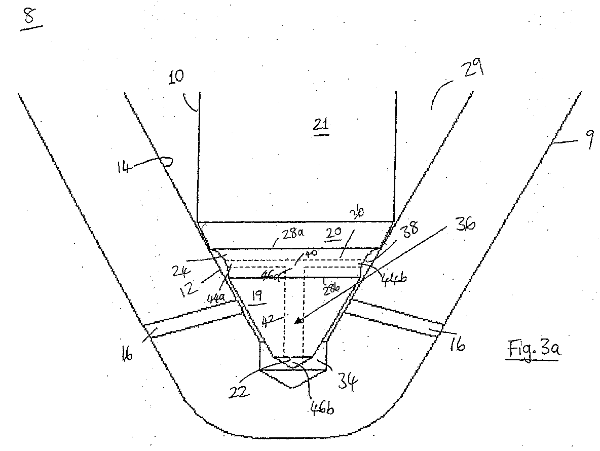
- Figure 3a shows an injection nozzle 8 of a first embodiment of the invention, which provides improved performance compared with the injection nozzle illustrated in Figures 2a and 2b.
- FIG 3a similar parts to those shown in Figure 2b are denoted with like reference numerals.
- the nozzle 8 illustrated in Figure 3a includes a valve needle 10 that is slidable within a bore 14 defined in a nozzle body 9, and engageable with a seating surface 12 provided by the bore 14.
- the valve needle 10 also comprises at least four distinct regions: a first region 21, a second region 20, a third region provided with an annular groove 24, and a valve tip region 19, as previously described and illustrated in Figure 2b.
- the annular groove 24 together with the region of the bore 14 between the upper and lower seats 28a and 28b defines an annular groove volume 38.
- valve needle 10 of the present invention there is, however, defined a fuel passageway 36 (illustrated by the dashed line) for permitting trapped fuel to flow directly from the annular groove volume 38 to the sac volume 34 upon closure of the injection nozzle 8 so that premature injection does not occur.
- the fuel passageway 36 comprises a first substantially radial bore 40 which is in fluid communication with a second substantially axial bore 42 which (in this particular example) lies in parallel to the main longitudinal axis of the valve needle 10.
- the radial bore 40 is formed in that region of the valve needle which is provided with the annular groove 24, so that the first and second inlet ends 44a, 44b on the bore 44 open at the surface of the needle in the annular groove volume 38.
- the first 44a and second 44b inlet ends are located diametrically opposite one another, as shown in Figure 3b.
- a central portion of the radial bore 40 is fluidly connected to an inlet end 46a of the axial bore 42.
- an outlet end 46b of the axial bore 42 opens from the chamfered tip 22 of the valve needle 10 into the sac volume 34 located at the downstream end of the bore 14.
- Fuel in the supply chamber 29 may become trapped in the annular groove volume 38 after an injection event, but is able to flow through the fuel passageway 36 through the radial bore 40 into axial bore 42 and, hence into the sac volume 34. Due to the clearance between the outer surface of the valve tip region 19 and the bore 14, fuel in the sac volume can escape to the nozzle outlets 16, thus providing relief of pressure in the annular groove volume 38.
- FIG 4 An alternative embodiment of the invention is shown in Figure 4, in which similar parts to the injection nozzle 8 of Figure 3 have like reference numerals.
- the injection nozzle 8 of this embodiment is identical to the previous embodiment, except that the fuel passageway 36 in this embodiment comprises a single bore 42 which extends diagonally through the valve needle 10.
- the diagonal bore 42 in this case has a single inlet end 46a which opens into the annular groove volume 38, and a single outlet end 46b which opens at the surface of the tapered region 19 of the valve needle 10 just upstream of the sac volume 34.
- Fuel in the supply chamber 29 may become trapped in the annular groove volume 38 after an injection event, but is able to flow through the diagonal bore 42 and hence into the sac volume 34. Due to the clearance between the outer surface of the valve tip region 19 and the bore 14, fuel in the sac volume 34 can escape to the nozzle outlets 16, thus providing relief of pressure in the annular groove volume 38.
- FIG. 5a A third embodiment of the present invention is illustrated in Figures 5a and 5b, in which similar parts of the injection nozzle 8 of the previously described embodiments have like reference numerals.
- a fuel injection nozzle 8 comprising a valve needle 10 that is slidable within a bore 14 provided in the nozzle body 9.
- the valve needle 10 also comprises four distinct regions: a first region 21, a second frusto-conical region 20, a third region having an annular groove 24, and a tapered valve tip region 19, as previously described and illustrated in Figures 2 to 4.
- valve needle 10 in a worn state is engageable with both the upper seating line 28a and the lower seating line 28b, such that an annular groove volume 38 is defined by the outer surface of the annular groove 24 of the valve needle 10 and the surface 50 of the nozzle body bore 14.
- a fuel passageway 36 for permitting trapped fuel to flow from the annular groove volume 38 to the sac volume 34 is formed by one or more elongated grooves 48 which are defined in the bore 14 of the nozzle body 9 itself, rather than in the valve needle 10 as in the previously described embodiments. These grooves 48 can be seen more clearly in Figure 5b.
- the grooves 48 are defined at the lower tapered end of the nozzle body bore 14, immediately upstream of the sac volume 34.
- the grooves 48 are positioned so as to extend from a region of the bore 14 which is adjacent to the annular groove volume 38 in the needle 10.
- the grooves 48 When the valve needle 10 is in its lowermost (i.e. non-injecting) position, the grooves 48 extend to a region of the bore 14 just downstream of the outlets 16.
- the grooves 48 should not extend above the upper seating line 28a otherwise fuel would be able to flow from the supply chamber 29 and then to the injection nozzle outlets 16 when the valve needle is in its injecting position, thereby causing premature initiation of the following injection event.
- the grooves 48 are tapered in the upstream direction to improve flow efficiency (i.e.
- each of the grooves 48 may be substantially the same as the diameter, D, of the injection nozzle outlets 16.
- the depth, d, of a groove 48 is illustrated in Figure 5c, and may be approximately 30 microns.
- Figures 6a and 6b show a fourth embodiment of the present invention in which the elongated grooves 48 are formed in a different position in the inner surface 50 of the nozzle body 9 to those of the third embodiment.
- FIGs 6a and 6b similar parts to those shown in Figures 5a and 5b are noted with like reference numerals.
- the elongated grooves 48 extend from the annular groove 24 of the valve needle 10 to the sac volume 34, when the valve needle is in its seated position in the bore 14. This is more clearly illustrated in Figure 6b where a number of grooves 48 are shown alternately positioned between the nozzle outlets 16 formed in the nozzle body 9. As in the previously described embodiment, the grooves 48 define a fuel passageway 36 for permitting trapped fuel to escape from the annular groove volume 38 so that premature injection does not occur.
- the grooves 48 should not extend above the upper seating line 28a otherwise fuel would be able to flow from the delivery chamber 29 and into the sac volume 34 when the valve needle 10 is in its injecting position, thereby causing premature initiation of the following injection event.
- the fuel passageway may comprise any suitable number of bores.
- two radial bores in fluid communication with a single axial bore, or two (or more) diagonal bores could be provided.
- at least one radial bore could be provided, with multiple axial or offset bores.
- any number of grooves may be formed in the surface of the bore formed in the nozzle body.
- the injection nozzle may also comprise a fuel passageway formed in the valve needle itself (the fuel passageway comprising any number of bores) in combination with one or more grooves defined in the surface of the bore formed in the nozzle body.
- the present invention is not limited to implementation in an injection nozzle having a valve covered orifice (VCO) with a sac volume, such as those shown in Figures 3 to 6, but may also be implemented in a sac-type injection nozzle in which there is a sac volume communicating directly with inlet ends of the nozzle outlets.
- VCO valve covered orifice
- the sac volume 34 is absent, and the provision of the grooves 48, such as those shown in Figure 5a, serves to improve flow efficiency and thus provides an additional benefit.
Abstract
Description
- The invention relates to an injection nozzle for use in a fuel injection system for an internal combustion engine. It relates particularly, but not exclusively, to an injection nozzle for use in a compression ignition internal combustion engine, in which a valve needle is engageable with a seating surface to control the injection of fuel to an associated combustion space through one or more nozzle outlets.
- In one known injection nozzle, for example as shown in Figure 1, a
valve needle 10 has aseating surface 28, or seating "line", which engages with aseat 12 defined by a nozzle body bore 14 within which thevalve needle 10 moves. In use, as thevalve needle 10 is moved away from theseat 12,injection nozzle outlets 16 are opened to enable high pressure fuel to be injected into the associated engine cylinder (not shown). When thevalve needle 10 is moved to re-engage with theseat 12, theoutlets 16 are closed and injection is terminated. - Immediately downstream of its
seating line 28, thevalve needle 10 includes adownstream region 18 of frusto-conical form defining a first cone angle which typically is around 60 degrees. Thenozzle body bore 14 is of conical form, and defines a second cone angle. Immediately upstream of itsseating line 28, thevalve needle 10 includes anupstream region 20 of frusto-conical form. Theupstream region 20 defines a third cone angle, that typically is around 45 degrees. Avalve tip region 19, arranged immediately downstream of theregion 18, terminates in achamfered tip 22. - It is a recognised problem in injection nozzle design that the effective diameter of the
seating line 28 varies with wear during nozzle service life. The effective seat diameter influences fuel delivery pressure, or nozzle opening pressure (i.e. that pressure at which the valve needle is caused to lift from theseat 12 of the bore 14), and this affects the quantity of fuel that is delivered during injection (i.e. when the valve needle is lifted). - It has been found that a nozzle of the type shown in Figure 1 has the effect of reducing variations in the effective seat diameter with nozzle wear. It has also been found that the variation of the effective seat diameter is reduced for significant periods of operation, and it is an advantage of this that delivery quantity variations are also reduced.
- An improvement to the injection nozzle shown in Figure 1 is described in US 5,890,660 (Delphi Technologies, Inc.). This document describes an injection nozzle 8 (shown in Figures 2a and 2b and described in detail later) in which a circumferential or
annular groove 24 is provided downstream of a valveneedle seating line 28, theannular groove 24 taking the place of thedownstream region 18 of the nozzle of Figure 1. Theannular groove 24 has the effect of preventing drift of the effective seat diameter in a downstream direction. - Testing of this particular injection nozzle design has shown improved seat wear and a reduction of the resultant fuel delivery drift which may occur in, for example, common rail systems due to the fuel being at high pressure (typically of the order of 300 to 1000 bar). However, delivery drift at high fuel pressures has been shown to increase fuel delivery, which has the effect of increasing emissions and therefore adversely affecting performance.
- It has been proposed that the reason for this increase in fuel delivery is due to a volume of fuel becoming trapped in the
annular groove 24 of the valve needle. This volume of trapped fuel acts to aid lifting of thevalve needle 10 from itsseat 12, and thus initiates the following injection event. This additional opening force is not present when the injection nozzle is new, as there is a small gap on the downstream edge of theannular groove 24. However, when thevalve needle 10 wears the gap closes, causing fuel to become trapped in thegroove 24. One solution to this problem is to provide external grooves on the surface of thevalve needle 10. A disadvantage of this particular arrangement is that wear can occur on the outside of the valve needle, or coking can occur on the seat, thereby producing delivery drift as the injection nozzle wears. - Another fuel injection nozzle is described in UK patent application no. 2,186,632 (Robert Bosch GmbH). This injection nozzle also has an annular groove formed in the valve needle, and further includes flow guiding wall portions formed on an elevation in the bottom of the blind bore in which the valve needle is disposed. However, the flow guiding wall portions are provided for the purpose of reducing the formation of so-called dead-water areas in the blind bore.
- It is an objection of the present invention to provide an improved injection nozzle which reduces the above mentioned problems.
- According to the present invention, there is provided an injection nozzle for an internal combustion engine, the injection nozzle comprising: a nozzle body provided with a blind bore within which a valve needle is moveable, the valve needle being engageable with a seating surface to control fuel flow between a supply chamber and at least one injection nozzle outlet, the valve needle being provided with an annular groove having an upstream edge defining an upper valve seating line and a downstream edge wherein, following wear in use, the lower edge becomes a lower valve seating line and the upper valve seating line and the lower valve seating line define an annular groove volume therebetween, and wherein a surface of the bore and the outer surface of the valve needle define a first flow path through which fuel flows from the supply chamber to the outlet(s) when the valve needle is lifted from the seating surface, the nozzle further including an additional flow path for said flow such that when, in use, the upper valve seating line and the lower valve seating line are in engagement with the seating surface, fuel is permitted to flow from the annular groove volume to the at least one injection nozzle outlet via the additional flow path.
- Thus, when the injection nozzle is in its worn state, and both the upper valve seating line and the lower valve seating line are engaged with the seating surface, fuel which would have become trapped in the annular groove volume (e.g., as defined by the annular groove and the adjacent internal surface of the bore in the known nozzle arrangement of US 5,890,660) is advantageously permitted to flow, via the additional flow path, into a sac volume formed at the end of the blind bore, and then through the nozzle outlet(s). The additional flow path therefore functions as a pressure relief means which acts to prevent premature injection.
- Conveniently, in one embodiment of the present invention, the additional flow path comprises at least one groove defined in a surface of the bore in the nozzle body. Preferably the at least one groove is substantially elongate in form.
- The at least one groove is preferably shaped and dimensioned such that when, in use, the upper valve seating line and the lower valve seating line are in engagement with the seating surface, the annular groove volume is in fluid communication with the sac volume. In one embodiment, the width of the at least one groove is substantially constant along its length, e.g. approximately 30 microns width. A small width ensures that the amount of fuel injected during an injection event is not appreciably increased due to the effectively increased volume of the sac volume. Alternatively, in a preferred embodiment, the at least one groove may taper in an upstream direction to improve flow efficiency.
- In another arrangement, the at least one groove may be shaped and dimensioned such that when, in use, the upper and lower valve seating lines are in engagement with the seating surface, the annular groove volume is in fluid communication with at least one injection nozzle outlet. Preferably, the width of the at least one groove at its downstream end is approximately the same as the diameter of the at least one injection nozzle outlet.
- Preferably, the depth of the at least one groove is approximately 30 microns.
- Preferably the seating surface is of frusto-conical form with a constant cone angle, and the valve needle further comprises a conical upstream section disposed upstream of the annular groove and a conical downstream section disposed downstream of the annular groove, the downstream section having a cone angle which is greater than that of the seating surface and the upstream section having a cone angle less than that of the seating surface.
- In an alternative embodiment of the present invention, the additional flow path comprises a fuel passageway formed in the valve needle itself. The fuel passageway may comprise at least one inclined, or diagonal, bore extending from the annular groove of the valve needle through the downstream section of the valve needle to open at a surface thereof. Alternatively, the fuel passageway may comprise at least one substantially radial bore extending between oppositely facing locations of the annular groove of the valve needle, the at least one substantially radial bore being in fluid communication with a plurality of further bores which open at a surface of the valve needle. The outlet ends of the plurality of further bores are preferably defined in the downstream section of the valve needle, and may communicate with a sac volume or one or more injection nozzle outlets.
- Other suitable arrangements of bores which enable fuel to escape from the annular groove volume are envisaged. For example, the axial bore(s) may be offset from the main longitudinal axis of the valve needle thereby defining a shorter bore which is easier to manufacture.
- In another embodiment of the present invention, the injection nozzle may comprise a fuel passageway formed in the valve needle itself in combination with at least one groove defined in the surface of the bore formed in the nozzle body.
- The bore (or bores) which form the fuel passageway may be formed using a laser, electro-discharge machining or spark erosion, or by any other suitable method.
- In a further embodiment, the aforementioned bores are substantially circular in cross-section, and may have a diameter of approximately 0.03 to 0.2 mm. However, the size and the shape of the bores may vary according to the application.
- Preferably the part of the valve needle downstream of the upper valve seating line is adapted to occupy a significant proportion of the part of the bore downstream of the upper valve seating line.
- Preferred embodiments of the invention will be described, by way example only, with reference to the accompanying drawings, in which:-
- Figure 1 is a sectional view of part of a known injection nozzle;
- Figure 2a is a sectional view of a known fuel injection nozzle as described in US 5,890,660;
- Figure 2b is a sectional view to an enlarged scale of part of the injection nozzle of Figure 2a;
- Figure 3a is a sectional side view of an injection nozzle according to a first embodiment of the present invention;
- Figure 3b is a sectional plan view of the injection nozzle of Figure 3a;
- Figure 4 is a sectional view of an injection nozzle according to a second embodiment of the present invention;
- Figure 5a is a sectional view of an injection nozzle according to a third embodiment of the present invention, showing the valve needle;
- Figure 5b is a sectional view of the injection nozzle of Figure 5a, wherein the surface of the internal bore in the nozzle body is visible;
- Figure 5c is a perspective view of a groove formed in the surface of the internal bore of Figure 5b;
- Figure 6a is a sectional view of an injection nozzle according to another embodiment of the present invention, showing the valve needle; and
- Figure 6b is a sectional view of the injection nozzle of Figure 6a, wherein the surface of the internal bore in the nozzle body is visible.
-
- As a background to the invention, there is shown in Figure 2a a
fuel injection nozzle 8 as described in US 5,890,660. Thefuel injection nozzle 8 comprises anozzle body 9 of stepped cylindrical form and, within thebody 9 and extending from the wider end thereof, there is formed ablind bore 14. At the blind end of thebore 14 there is formed aseating surface 12 defined by the internal surface of the bore. Intermediate the ends of thebore 14 there is formed anenlargement 12a which communicates with afuel inlet passage 13. Thefuel inlet passage 13 extends through adistance piece 26 and anozzle holder 15 to a fuel inlet which in use is connected to a source of high pressure fuel (e.g. a common rail). - The
nozzle body 9 is secured to thenozzle holder 15 by means of theusual cap nut 17 and, in use, the narrower portion of the nozzle body passes through a bore into a combustion space of the associated engine (not shown). - Slidable within the
bore 14 is avalve needle 10. Thevalve needle 10 intermediate theenlargement 12a and theseating surface 12 is of reduced diameter so as to define anannular supply chamber 29 through which fuel can flow when thevalve needle 10 is in the open position. - The
valve needle 10 is provided with anextension 20 which extends with a clearance through an aperture in thedistance piece 26. Theextension 20 is engaged by aspring abutment 31 against which is located one end of a coiledcompression spring 32, the other end of which bears against anabutment 33. Thespring 32 acts to maintain thevalve needle 10 engaged with theseating surface 12 in the closed position, and the chamber in which thespring 32 is located is connected to a drain (not shown) through apassage 35. - Turning now to Figure 2b, it can be seen that the
valve needle 10 includes four distinct regions. Afirst region 21 at the uppermost end of thevalve needle 10 is of substantially cylindrical form. Asecond region 20 of frusto-conical or part conical form is arranged immediately downstream of thefirst region 21 and defines, or includes, at its lowermost edge, an upper seating line 28a having a diameter D. Theupstream region 20 has an included angle with theseating surface 12 of 0.75 degrees in this example, so that its cone angle is slightly less than that of the seating surface. Athird region 24 of thevalve needle 10 is provided with anannular groove 24 in its outer surface. Thedownstream edge 28b of theannular groove 24 forms a boundary with a downstreamfourth region 19, which has a cone angle slightly greater than that of theseating surface 12. When the nozzle is new and in a closed position, there is engagement between thevalve needle 10 and theseating surface 12 along the upstream seating line 28a, but there is a clearance between the seatingsurface 12 and thevalve needle 10, particularly in the region of thedownstream edge 28b of theannular groove 24. Thefourth region 19 terminates in a chamferedtip 22 which extends into asac volume 34 defined at the blind end of the nozzle body bore 14. - The
nozzle body 9 is provided with a set of first andsecond nozzle outlets 16 which provide a flow path for fuel into the combustion chamber (not shown) from thesac volume 34. Thesac volume 34 is defined by theseating surface 12 and an outer surface of thevalve needle 10 in a region downstream of thelower edge 28b of theannular groove 24. The seating line 28a is engageable with theseating surface 12 to control fuel flow into thesac volume 34 from theupstream supply chamber 29. - In operation, when fuel under pressure is supplied to the
fuel inlet 13, fuel pressure acts on the surface of theextension 20 when thevalve needle 10 is seated, and a force is therefore generated on thevalve needle 10 in opposition to the force exerted by thespring 32. When the force due to the fuel pressure exceeds the spring force, thevalve needle 10 moves to the open position and fuel can then flow between thevalve needle 10 and theseating surface 12, and through thenozzle outlets 16. The pressure which is required to lift thevalve needle 10 from itsseating surface 12 is known in the art as the "nozzle opening pressure". When the flow of fuel to theinlet 13 ceases and the pressure within thesupply chamber 29 falls to a level less than the nozzle opening pressure, thevalve needle 10 will be returned into engagement with theseating surface 12 by the action of thespring 32. - In practice, following a period of use of the nozzle, the
valve needle 10 seats against the upper valve seating line 28a when in the non-injecting (i.e. closed) state, and may also seat against thelower edge 28b as thevalve needle 10 becomes worn. Once this wear occurs, thelower edge 28b defines alower seating line 28b and anannular groove volume 38 will be defined by the outer surface of theannular groove 24 of thevalve needle 10 and the inner surface of the nozzle body bore 14. As described previously, fuel which becomes trapped in thisannular groove volume 38 upon closing of the injection nozzle may cause premature injection due to an increased hydraulic opening force being applied to theneedle 10. - Figure 3a shows an
injection nozzle 8 of a first embodiment of the invention, which provides improved performance compared with the injection nozzle illustrated in Figures 2a and 2b. In Figure 3a, similar parts to those shown in Figure 2b are denoted with like reference numerals. - Again, the
nozzle 8 illustrated in Figure 3a includes avalve needle 10 that is slidable within abore 14 defined in anozzle body 9, and engageable with aseating surface 12 provided by thebore 14. Thevalve needle 10 also comprises at least four distinct regions: afirst region 21, asecond region 20, a third region provided with anannular groove 24, and avalve tip region 19, as previously described and illustrated in Figure 2b. Theannular groove 24 together with the region of thebore 14 between the upper andlower seats 28a and 28b defines anannular groove volume 38. In thevalve needle 10 of the present invention there is, however, defined a fuel passageway 36 (illustrated by the dashed line) for permitting trapped fuel to flow directly from theannular groove volume 38 to thesac volume 34 upon closure of theinjection nozzle 8 so that premature injection does not occur. - The
fuel passageway 36 comprises a first substantially radial bore 40 which is in fluid communication with a second substantiallyaxial bore 42 which (in this particular example) lies in parallel to the main longitudinal axis of thevalve needle 10. The radial bore 40 is formed in that region of the valve needle which is provided with theannular groove 24, so that the first and second inlet ends 44a, 44b on the bore 44 open at the surface of the needle in theannular groove volume 38. In this example, the first 44a and second 44b inlet ends are located diametrically opposite one another, as shown in Figure 3b. A central portion of the radial bore 40 is fluidly connected to an inlet end 46a of theaxial bore 42. Returning to Figure 3a, an outlet end 46b of theaxial bore 42 opens from the chamferedtip 22 of thevalve needle 10 into thesac volume 34 located at the downstream end of thebore 14. Fuel in thesupply chamber 29 may become trapped in theannular groove volume 38 after an injection event, but is able to flow through thefuel passageway 36 through the radial bore 40 intoaxial bore 42 and, hence into thesac volume 34. Due to the clearance between the outer surface of thevalve tip region 19 and thebore 14, fuel in the sac volume can escape to thenozzle outlets 16, thus providing relief of pressure in theannular groove volume 38. - An alternative embodiment of the invention is shown in Figure 4, in which similar parts to the
injection nozzle 8 of Figure 3 have like reference numerals. Theinjection nozzle 8 of this embodiment is identical to the previous embodiment, except that thefuel passageway 36 in this embodiment comprises asingle bore 42 which extends diagonally through thevalve needle 10. Thediagonal bore 42 in this case has a single inlet end 46a which opens into theannular groove volume 38, and a single outlet end 46b which opens at the surface of the taperedregion 19 of thevalve needle 10 just upstream of thesac volume 34. Fuel in thesupply chamber 29 may become trapped in theannular groove volume 38 after an injection event, but is able to flow through thediagonal bore 42 and hence into thesac volume 34. Due to the clearance between the outer surface of thevalve tip region 19 and thebore 14, fuel in thesac volume 34 can escape to thenozzle outlets 16, thus providing relief of pressure in theannular groove volume 38. - A third embodiment of the present invention is illustrated in Figures 5a and 5b, in which similar parts of the
injection nozzle 8 of the previously described embodiments have like reference numerals. Referring firstly to Figure 5a, there is shown part of afuel injection nozzle 8 comprising avalve needle 10 that is slidable within abore 14 provided in thenozzle body 9. Thevalve needle 10 also comprises four distinct regions: afirst region 21, a second frusto-conical region 20, a third region having anannular groove 24, and a taperedvalve tip region 19, as previously described and illustrated in Figures 2 to 4. - As in the previously described embodiments, the
valve needle 10 in a worn state is engageable with both the upper seating line 28a and thelower seating line 28b, such that anannular groove volume 38 is defined by the outer surface of theannular groove 24 of thevalve needle 10 and thesurface 50 of the nozzle body bore 14. - In this embodiment of the present invention, a
fuel passageway 36 for permitting trapped fuel to flow from theannular groove volume 38 to thesac volume 34 is formed by one or moreelongated grooves 48 which are defined in thebore 14 of thenozzle body 9 itself, rather than in thevalve needle 10 as in the previously described embodiments. Thesegrooves 48 can be seen more clearly in Figure 5b. - The
grooves 48 are defined at the lower tapered end of the nozzle body bore 14, immediately upstream of thesac volume 34. Thegrooves 48 are positioned so as to extend from a region of thebore 14 which is adjacent to theannular groove volume 38 in theneedle 10. When thevalve needle 10 is in its lowermost (i.e. non-injecting) position, thegrooves 48 extend to a region of thebore 14 just downstream of theoutlets 16. However, thegrooves 48 should not extend above the upper seating line 28a otherwise fuel would be able to flow from thesupply chamber 29 and then to theinjection nozzle outlets 16 when the valve needle is in its injecting position, thereby causing premature initiation of the following injection event. In one preferred embodiment, thegrooves 48 are tapered in the upstream direction to improve flow efficiency (i.e. having an enlarged relatively upstream end compared to a smaller downstream end). If the grooves are tapered, then the width, w, of the grooves at their downstream end are substantially the same as the diameter, D, of theinjection nozzle outlets 16. If the grooves are not tapered, then the width, w, of each of thegrooves 48 may be substantially the same as the diameter, D, of theinjection nozzle outlets 16. The depth, d, of agroove 48 is illustrated in Figure 5c, and may be approximately 30 microns. - As can be seen from Figure 5a, when the
valve needle 10 is in its seated position within thebore 14, thegrooves 48 permit flow of fuel from theannular groove volume 38 to the nozzle outlet(s) 16. Hence, the pressure within theannular groove 38 is relieved and this provides the benefits discussed above. Ideally, asingle groove 48 is provided for eachnozzle outlet 16, although it is possible to havefewer grooves 48 thannozzle outlets 16. - Figures 6a and 6b show a fourth embodiment of the present invention in which the
elongated grooves 48 are formed in a different position in theinner surface 50 of thenozzle body 9 to those of the third embodiment. In Figures 6a and 6b, similar parts to those shown in Figures 5a and 5b are noted with like reference numerals. - Referring firstly to Figure 6a, it can be seen that in this embodiment, the
elongated grooves 48 extend from theannular groove 24 of thevalve needle 10 to thesac volume 34, when the valve needle is in its seated position in thebore 14. This is more clearly illustrated in Figure 6b where a number ofgrooves 48 are shown alternately positioned between thenozzle outlets 16 formed in thenozzle body 9. As in the previously described embodiment, thegrooves 48 define afuel passageway 36 for permitting trapped fuel to escape from theannular groove volume 38 so that premature injection does not occur. - Again, in this embodiment of the invention, the
grooves 48 should not extend above the upper seating line 28a otherwise fuel would be able to flow from thedelivery chamber 29 and into thesac volume 34 when thevalve needle 10 is in its injecting position, thereby causing premature initiation of the following injection event. - Having described particular preferred embodiments of the present invention, it is to be appreciated that the embodiments in question are exemplary only, and that variations and modifications such as will occur to those possessed of the appropriate knowledge and skill may be made without departure from the spirit and scope of the invention as set forth in the appended claims. For example, the fuel passageway may comprise any suitable number of bores. For instance, two radial bores in fluid communication with a single axial bore, or two (or more) diagonal bores could be provided. Alternatively, at least one radial bore could be provided, with multiple axial or offset bores. Also, any number of grooves may be formed in the surface of the bore formed in the nozzle body. The injection nozzle may also comprise a fuel passageway formed in the valve needle itself (the fuel passageway comprising any number of bores) in combination with one or more grooves defined in the surface of the bore formed in the nozzle body.
- The present invention is not limited to implementation in an injection nozzle having a valve covered orifice (VCO) with a sac volume, such as those shown in Figures 3 to 6, but may also be implemented in a sac-type injection nozzle in which there is a sac volume communicating directly with inlet ends of the nozzle outlets. In a sac-less VCO-type nozzle, the
sac volume 34 is absent, and the provision of thegrooves 48, such as those shown in Figure 5a, serves to improve flow efficiency and thus provides an additional benefit.
Claims (12)
- An injection nozzle (8) for an internal combustion engine, the injection nozzle (8) comprising: a nozzle body (9) provided with a blind bore (14) within which a valve needle (10) is moveable, the valve needle (10) being engageable with a seating surface (12) to control fuel flow between a supply chamber (29) and at least one injection nozzle outlet (16), the valve needle being provided with an annular groove (24) having an upstream edge defining an upper valve seating line (28a) and a downstream edge wherein, following wear in use, the lower edge becomes a lower valve seating line (28b) and the upper valve seating line (28a) and the lower valve seating line (28b) define an annular groove volume (38) therebetween, and wherein a surface of the bore (14) and the outer surface of the valve needle (10) define a first flow path through which fuel flows from the supply chamber (29) to the outlet(s) (16) when the valve needle is lifted from the seating surface (12), the nozzle (8) further including an additional flow path for said flow such that when, in use, the upper valve seating line (28a) and the lower valve seating line (28b) are in engagement with the seating surface (12), fuel is permitted to flow from the annular groove volume (38) to the at least one injection nozzle outlet via the additional flow path.
- An injection nozzle (8) according to Claim 1, wherein the additional flow path comprises at least one groove (48) defined in the inner surface (50) of the nozzle body (9).
- An injection nozzle (8) according to Claim 2, wherein the at least one groove (48) is substantially elongate in form.
- An injection nozzle (8) according to Claim 2 or Claim 3, wherein the at least one groove (48) is shaped and dimensioned such that, when, in use, the upper valve seating line (28a) and the lower valve seating line (28b) are in engagement with the seating surface (12), the annular groove volume (38) is in fluid communication with at least one injection nozzle outlet (16).
- An injection nozzle (8) according to Claim 2 or Claim 3, wherein the at least one groove (48) is shaped and dimensioned such that, when, in use, the upper valve seating line (28a) and the lower valve seating line (28b) are in engagement with the seating surface, the annular groove volume (38) is in fluid communication with the sac volume (34).
- An injection nozzle (8) according to any of Claims 2 to 5, wherein the width of the at least one groove (48) is approximately the same as the diameter of the at least one injection nozzle outlet (16).
- An injection nozzle (8) according to any of Claims 2 to 5, wherein the at least one groove (48) tapers in an upstream direction.
- An injection nozzle (8) according to any of Claims 1 to 7, wherein the additional flow path comprises a fuel passageway (36) formed in the valve needle (10).
- An injection nozzle (8) according to Claim 8, wherein the fuel passageway (36) comprises at least one inclined bore (42) extending from the annular groove (24) of the valve needle (10) through a downstream section (21) of the valve needle (10) to open at a surface thereof.
- An injection nozzle (8) according to Claim 8, wherein the fuel passageway (36) comprises at least one substantially radial bore (40) extending between oppositely facing locations of the annular groove (24) of the valve needle (10), the at least one substantially radial bore (40) being in fluid communication with a substantially axial bore (42) having an outlet end (46b) defined in the downstream section (21) of the valve needle (10).
- An injection nozzle (8) according to Claim 8, wherein the fuel passageway (36) comprises at least one substantially radial bore (40) extending between oppositely facing locations of the annular groove (24) of the valve needle (10), the at least one substantially radial bore (40) being in fluid communication with a plurality of further bores which open at a surface of the valve needle (10).
- An injection nozzle (8) according to any preceding claim, wherein the seating surface (12) is of frusto-conical form with a constant cone angle, and the valve needle (10) further comprises a conical upstream section (20) disposed upstream of the annular groove (24) and a conical downstream section (21) disposed downstream of the annular groove (24), the downstream section (21) having a cone angle which is greater than that of the seating surface (12) and the upstream section (20) having a cone angle less than that of the seating surface.
Priority Applications (1)
| Application Number | Priority Date | Filing Date | Title |
|---|---|---|---|
| EP04251360A EP1496246A1 (en) | 2003-07-07 | 2004-03-10 | Injection nozzle |
Applications Claiming Priority (3)
| Application Number | Priority Date | Filing Date | Title |
|---|---|---|---|
| EP03254291 | 2003-07-07 | ||
| EP03254291 | 2003-07-07 | ||
| EP04251360A EP1496246A1 (en) | 2003-07-07 | 2004-03-10 | Injection nozzle |
Publications (1)
| Publication Number | Publication Date |
|---|---|
| EP1496246A1 true EP1496246A1 (en) | 2005-01-12 |
Family
ID=33454344
Family Applications (1)
| Application Number | Title | Priority Date | Filing Date |
|---|---|---|---|
| EP04251360A Ceased EP1496246A1 (en) | 2003-07-07 | 2004-03-10 | Injection nozzle |
Country Status (1)
| Country | Link |
|---|---|
| EP (1) | EP1496246A1 (en) |
Cited By (2)
| Publication number | Priority date | Publication date | Assignee | Title |
|---|---|---|---|---|
| WO2011160991A1 (en) * | 2010-06-22 | 2011-12-29 | Robert Bosch Gmbh | Injector, in particular common-rail injector, and fuel injection system with an injector |
| EP3309386A1 (en) * | 2016-10-14 | 2018-04-18 | Delphi International Operations Luxembourg S.à r.l. | Fuel injector valve member |
Citations (13)
| Publication number | Priority date | Publication date | Assignee | Title |
|---|---|---|---|---|
| GB2158151A (en) * | 1984-04-26 | 1985-11-06 | Lucas Ind Plc | Fuel injection nozzles |
| GB2186632A (en) | 1986-02-18 | 1987-08-19 | Bosch Gmbh Robert | Fuel injection nozzle for i.c. engines |
| JPH10252605A (en) * | 1997-03-14 | 1998-09-22 | Toyota Autom Loom Works Ltd | Fuel injection nozzle for diesel engine |
| US5890660A (en) | 1994-12-20 | 1999-04-06 | Lucas Industries Public Limited Company | Fuel injection nozzle |
| US5947389A (en) * | 1996-06-06 | 1999-09-07 | Zexel Corporation | Variable nozzle hole type fuel injection nozzle |
| US5950930A (en) * | 1996-11-07 | 1999-09-14 | Robert Bosch Gmbh | Fuel injection valve for internal combustion engines |
| JP2000265927A (en) * | 1999-03-16 | 2000-09-26 | Toyota Motor Corp | Fuel injection nozzle |
| DE10020148A1 (en) * | 1999-04-26 | 2000-11-16 | Toyota Motor Co Ltd | Fuel injector assembly for an internal combustion engine, comprises angular fuel ports arranged around a peripheral edge |
| DE10109345A1 (en) * | 2000-02-29 | 2001-08-30 | Denso Corp | Fuel injection nozzle head offers seating face for needle valve seat where downstream shutter stabilizes fuel flow section upstream of port at all needle lift values. |
| US20020179743A1 (en) * | 2000-06-27 | 2002-12-05 | Rainer Haeberer | Fuel injection valve for internal combustion engines |
| WO2004027254A1 (en) * | 2002-09-13 | 2004-04-01 | Robert Bosch Gmbh | Fuel injection valve for internal combustion engines |
| WO2004031570A1 (en) * | 2002-09-27 | 2004-04-15 | Robert Bosch Gmbh | Fuel injection valve for internal combustion engines |
| WO2004070197A1 (en) * | 2003-02-03 | 2004-08-19 | Robert Bosch Gmbh | Injection nozzle |
-
2004
- 2004-03-10 EP EP04251360A patent/EP1496246A1/en not_active Ceased
Patent Citations (14)
| Publication number | Priority date | Publication date | Assignee | Title |
|---|---|---|---|---|
| GB2158151A (en) * | 1984-04-26 | 1985-11-06 | Lucas Ind Plc | Fuel injection nozzles |
| GB2186632A (en) | 1986-02-18 | 1987-08-19 | Bosch Gmbh Robert | Fuel injection nozzle for i.c. engines |
| US5890660A (en) | 1994-12-20 | 1999-04-06 | Lucas Industries Public Limited Company | Fuel injection nozzle |
| US5947389A (en) * | 1996-06-06 | 1999-09-07 | Zexel Corporation | Variable nozzle hole type fuel injection nozzle |
| US5950930A (en) * | 1996-11-07 | 1999-09-14 | Robert Bosch Gmbh | Fuel injection valve for internal combustion engines |
| JPH10252605A (en) * | 1997-03-14 | 1998-09-22 | Toyota Autom Loom Works Ltd | Fuel injection nozzle for diesel engine |
| JP2000265927A (en) * | 1999-03-16 | 2000-09-26 | Toyota Motor Corp | Fuel injection nozzle |
| DE10020148A1 (en) * | 1999-04-26 | 2000-11-16 | Toyota Motor Co Ltd | Fuel injector assembly for an internal combustion engine, comprises angular fuel ports arranged around a peripheral edge |
| DE10109345A1 (en) * | 2000-02-29 | 2001-08-30 | Denso Corp | Fuel injection nozzle head offers seating face for needle valve seat where downstream shutter stabilizes fuel flow section upstream of port at all needle lift values. |
| US20020179743A1 (en) * | 2000-06-27 | 2002-12-05 | Rainer Haeberer | Fuel injection valve for internal combustion engines |
| WO2004027254A1 (en) * | 2002-09-13 | 2004-04-01 | Robert Bosch Gmbh | Fuel injection valve for internal combustion engines |
| WO2004031570A1 (en) * | 2002-09-27 | 2004-04-15 | Robert Bosch Gmbh | Fuel injection valve for internal combustion engines |
| EP1546547A1 (en) | 2002-09-27 | 2005-06-29 | Robert Bosch Gmbh | Fuel injection valve for internal combustion engines |
| WO2004070197A1 (en) * | 2003-02-03 | 2004-08-19 | Robert Bosch Gmbh | Injection nozzle |
Non-Patent Citations (2)
| Title |
|---|
| PATENT ABSTRACTS OF JAPAN vol. 1998, no. 14 31 December 1998 (1998-12-31) * |
| PATENT ABSTRACTS OF JAPAN vol. 2000, no. 12 3 January 2001 (2001-01-03) * |
Cited By (3)
| Publication number | Priority date | Publication date | Assignee | Title |
|---|---|---|---|---|
| WO2011160991A1 (en) * | 2010-06-22 | 2011-12-29 | Robert Bosch Gmbh | Injector, in particular common-rail injector, and fuel injection system with an injector |
| EP3309386A1 (en) * | 2016-10-14 | 2018-04-18 | Delphi International Operations Luxembourg S.à r.l. | Fuel injector valve member |
| FR3057623A1 (en) * | 2016-10-14 | 2018-04-20 | Delphi International Operations Luxembourg S.A R.L. | VALVE MEMBER OF A FUEL INJECTOR |
Similar Documents
| Publication | Publication Date | Title |
|---|---|---|
| US5890660A (en) | Fuel injection nozzle | |
| US6827297B2 (en) | Fuel injection valve for internal combustion engines | |
| EP1079094B1 (en) | Fuel injector | |
| US7168412B2 (en) | Injection nozzle | |
| EP1717440B1 (en) | Fluid injection nozzle | |
| US20070290075A1 (en) | Fuel Injection Valve For Internal Combustion Engines | |
| US5765755A (en) | Injection rate shaping nozzle assembly for a fuel injector | |
| US20070120087A1 (en) | Valve body with multiconical geometry at the valve seat | |
| EP0283154A1 (en) | Fuel injection nozzle | |
| US20120012681A1 (en) | Fuel injector having balanced and guided plunger | |
| EP0844383B1 (en) | Injector | |
| US20030173428A1 (en) | Fuel-injection valve for internal combustion engines | |
| EP1245822A2 (en) | Fuel injector with a restricted flow means in the control valve arrangement | |
| US9297343B2 (en) | Needle for needle valve | |
| EP1496246A1 (en) | Injection nozzle | |
| US8002205B2 (en) | Injection nozzle | |
| EP0972934A2 (en) | Fuel injector | |
| US6502554B1 (en) | Fuel injection valve for internal combustion engines | |
| GB2335000A (en) | Fuel injector having a restricted fuel flow path provided by a needle valve | |
| EP1033488B1 (en) | Fuel injector | |
| KR102244948B1 (en) | Fuel injection nozzle | |
| EP0460326A1 (en) | Fuel injection nozzles | |
| EP1498602B1 (en) | Injection nozzle | |
| EP1344931B1 (en) | Injection nozzle | |
| GB2389390A (en) | Fuel injection nozzle with inclined grooves formed in the valve needle |
Legal Events
| Date | Code | Title | Description |
|---|---|---|---|
| PUAI | Public reference made under article 153(3) epc to a published international application that has entered the european phase |
Free format text: ORIGINAL CODE: 0009012 |
|
| AK | Designated contracting states |
Kind code of ref document: A1 Designated state(s): AT BE BG CH CY CZ DE DK EE ES FI FR GB GR HU IE IT LI LU MC NL PL PT RO SE SI SK TR |
|
| AX | Request for extension of the european patent |
Extension state: AL HR LT LV MK |
|
| RIN1 | Information on inventor provided before grant (corrected) |
Inventor name: LIMMER, ANDREW Inventor name: PIMENTA, RICARDO Inventor name: SCHOEPPE, DETLEV Inventor name: LAMBERT, MALCOLM DAVID DICK |
|
| 17P | Request for examination filed |
Effective date: 20050316 |
|
| AKX | Designation fees paid |
Designated state(s): AT BE BG CH CY CZ DE DK EE ES FI FR GB GR HU IE IT LI LU MC NL PL PT RO SE SI SK TR |
|
| RIN1 | Information on inventor provided before grant (corrected) |
Inventor name: LIMMER, ANDREW Inventor name: PIMENTA, RICARDO Inventor name: SCHOEPPE, DETLEV Inventor name: LAMBERT, MALCOLM DAVID DICK |
|
| 17Q | First examination report despatched |
Effective date: 20080529 |
|
| RAP1 | Party data changed (applicant data changed or rights of an application transferred) |
Owner name: DELPHI TECHNOLOGIES HOLDING S.A.R.L. |
|
| STAA | Information on the status of an ep patent application or granted ep patent |
Free format text: STATUS: THE APPLICATION HAS BEEN REFUSED |
|
| 18R | Application refused |
Effective date: 20131206 |