EP1495945B1 - A cross member for under the dashboard of a motor vehicle - Google Patents
A cross member for under the dashboard of a motor vehicle Download PDFInfo
- Publication number
- EP1495945B1 EP1495945B1 EP04103288A EP04103288A EP1495945B1 EP 1495945 B1 EP1495945 B1 EP 1495945B1 EP 04103288 A EP04103288 A EP 04103288A EP 04103288 A EP04103288 A EP 04103288A EP 1495945 B1 EP1495945 B1 EP 1495945B1
- Authority
- EP
- European Patent Office
- Prior art keywords
- cross member
- dashboard
- welding
- section
- box
- Prior art date
- Legal status (The legal status is an assumption and is not a legal conclusion. Google has not performed a legal analysis and makes no representation as to the accuracy of the status listed.)
- Expired - Lifetime
Links
- 239000002184 metal Substances 0.000 claims abstract description 12
- 238000003466 welding Methods 0.000 claims description 17
- 238000000034 method Methods 0.000 claims description 13
- 238000004519 manufacturing process Methods 0.000 claims 1
- 238000009429 electrical wiring Methods 0.000 description 1
- 238000012423 maintenance Methods 0.000 description 1
- 239000000463 material Substances 0.000 description 1
- 239000007769 metal material Substances 0.000 description 1
- 238000012986 modification Methods 0.000 description 1
- 230000004048 modification Effects 0.000 description 1
- 230000001681 protective effect Effects 0.000 description 1
- 239000002994 raw material Substances 0.000 description 1
- 230000001105 regulatory effect Effects 0.000 description 1
- 238000009877 rendering Methods 0.000 description 1
Images

Classifications
-
- B—PERFORMING OPERATIONS; TRANSPORTING
- B62—LAND VEHICLES FOR TRAVELLING OTHERWISE THAN ON RAILS
- B62D—MOTOR VEHICLES; TRAILERS
- B62D25/00—Superstructure or monocoque structure sub-units; Parts or details thereof not otherwise provided for
- B62D25/08—Front or rear portions
- B62D25/14—Dashboards as superstructure sub-units
- B62D25/145—Dashboards as superstructure sub-units having a crossbeam incorporated therein
-
- B—PERFORMING OPERATIONS; TRANSPORTING
- B60—VEHICLES IN GENERAL
- B60R—VEHICLES, VEHICLE FITTINGS, OR VEHICLE PARTS, NOT OTHERWISE PROVIDED FOR
- B60R21/00—Arrangements or fittings on vehicles for protecting or preventing injuries to occupants or pedestrians in case of accidents or other traffic risks
- B60R21/02—Occupant safety arrangements or fittings, e.g. crash pads
- B60R21/04—Padded linings for the vehicle interior ; Energy absorbing structures associated with padded or non-padded linings
- B60R21/045—Padded linings for the vehicle interior ; Energy absorbing structures associated with padded or non-padded linings associated with the instrument panel or dashboard
Definitions
- the present invention relates to a cross member for under the dashboard of a motor vehicle.
- the devices provided for driving (steering wheel and possibly the gear lever) and the instrumentation provided on board the vehicle (instrument board and panel for regulating the on-board systems) are housed in a dashboard, generally made of plastic material, which extends in the transverse direction in the front area of the passenger compartment, in front of the driver and passenger seats. All the wires for supply and control of the instruments, indicating meters and devices of an electrical type carried by the dashboard are gathered together in a harness, which traverses the entire rear surface of the dashboard and is provided with one or more connectors for interfacing with the electrical wiring system of the motor vehicle.
- the cross member for under the dashboard is a metal bar located underneath the dashboard in a direction transverse to the direction of travel of the vehicle and has the purpose of providing a support for the dashboard itself, for the devices associated thereto and for the harness of wires.
- Known cross members for supporting the dashboard generally consist of a tube, on which the brackets are connected by welding.
- brackets In the first place, fixing of the brackets to a cylindrical surface requires the use of techniques of seam welding, which are notoriously burdensome in terms of time, investments and operating costs. Furthermore, the cylindrical surface does not provide unique geometrical references for positioning the brackets.
- EP-A-0673829 and WO03/045763 disclose respective cross members obtained by roll forming. However, no indication is given relating to the details of the roll forming process.
- the purpose of the present invention is to provide a cross member for under the dashboard which will be free from the drawbacks described above.
- Figure 1 illustrates a cross member for under the dashboard 1 having ends 2 designed to be rigidly constrained to the body of the motor vehicle via a pair of brackets 3. Represented moreover schematically with a dashed line in the figure is a dashboard 4 supported by the cross member 1.
- the dashboard 4 integrally comprises a main top portion extending in a transverse direction throughout the width of the passenger compartment of the vehicle and carrying, in a way not illustrated, the steering wheel and the on-board instrumentation (not illustrated).
- the dashboard 4 further comprises, optionally, a bottom block 5, which is substantially parallelepipedal, houses a gear lever 6, and is arranged in a central and bottom position of the dashboard 4.
- brackets and supporting structures Connected to the cross member 1 are various brackets and supporting structures; some examples of said brackets and structures are described in what follows, purely by way of example, it being evident to the person skilled in the branch that the shapes and arrangement of said elements may vary according to the specific requirements of the motor vehicle.
- the dashboard 4 is connected to the cross member 1 by means of a pair of supporting brackets 14 that extend in a direction opposite to the block 5 with respect to the cross member 1.
- a supporting shaped metal structure 15 comprising integrally a horizontal plane surface 16 delimited by a pair of side appendages 17 welded to the cross member 1, and a substantially vertical wall 18, which extends as far as the block 5.
- the cross member 1 carries a support 19 for the steering column and a pair of brackets 21 for carrying an instrument panel 22.
- the cross member 1 and the brackets welded thereto form, as a whole, a supporting structure 23.
- the cross member 1 is obtained by continuous roll forming starting from a metal strip that is fed longitudinally through a succession of roll forming workstations comprising pairs of shaped rollers, and undergoes folding along lines parallel to the direction of feed.
- the strip is deformed transversally and, when the side ends are set on top of one another, is welded with techniques which may or may not use weld metal, for example TIG welding or spot welding, thus assuming a closed polygonal profile.
- the folding angles which are defined in a plane orthogonal to the direction of feed, depend substantially upon the nature of the metal material used and can even reach 180°, thus rendering possible the forming of closed sections having linear projections. Subsequent operations that enable folding of the bar also according to angles not belonging to a plane orthogonal to the direction of feed are moreover possible.
- the cross member 1 illustrated in Figure 2 comprises a box-like body 28 which has a closed section with substantially rectilinear sides, presenting in particular: a horizontal top side 29; a vertical front side 30; an oblique side 31, which faces the front side 30, converges downwards with respect to the latter, and has a top fillet with the top side 30; and a bottom concave portion 32 set between the front side 30 and the oblique side 31.
- the concave portion 32 is defined by a pair of sides 33, 34, arranged to form a V set upside down, and is delimited by a pair of bottom ribs 35, 36, which extend in cantilever fashion from the box-like body 28 between the front side 30 and the bottom side 33 and, respectively, between the oblique side 31 and the bottom side 34, and are each defined by two layers of sheet metal folded at 180° on top of one another.
- the rib 35 is vertical and extends downwards as prolongation of the front side 30; the rib 36 extends in the direction of the bottom side 34, thus diverging downwards with respect to the rib 35.
- the ribs 35, 36 delimit, together with the concave portion 32, a seat 37 which houses a harness 38 of electrical wires, which extends longitudinally, in use, underneath the dashboard 4 and is designed to interconnect electrical instruments and devices of the dashboard itself with the wiring system of the vehicle.
- the cross member 1 comprises a closing edge 39, which extends horizontally starting from a top end of the front side 30 and substantially along the prolongation of the top side 29, and comprises a first side edge 40 and a second side edge 41 of the strip constituting the cross member 1, which are set on top of one another and welded together via spot welding or seam welding, for example by roll-seam welding.
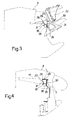
- Figures 3 and 4 illustrate some examples of fixing of the brackets 3, 14 and 21 to the cross member 1.
- the brackets 3 and 21 are welded to the cross member 1 both on the vertical wall, defined by the front side 30 of the box-like body 28 and by the rib 35, and underneath the closing edge 39.
- the brackets 14 are conveniently welded to the oblique side 31, to the top side 29, and to the rib 36.
- brackets 3, 14 and 21 simplifies the operation of welding of the brackets 3, 14 and 21, enabling seam welding, which is a versatile but costly process, to be replaced by spot welding, which is highly advantageous from an economic standpoint and can be readily automated.
- positioning of the brackets can be defined uniquely thanks to the contact with two or more plane walls.
- the possibility of adopting the technique of forming metal section further enables, by appropriately equipping the rollers that make up the line, a wide range of sectional elements and geometries to be obtained, thus making it possible to optimize the cross section of the cross member 1 according to design parameters, such as mechanical resistance, overall dimension and weight, and taking into account particular operating requirements.
- design parameters such as mechanical resistance, overall dimension and weight, and taking into account particular operating requirements.
- section of the cross member may be varied, as well as the shape and the number of brackets.
Landscapes
- Engineering & Computer Science (AREA)
- Chemical & Material Sciences (AREA)
- Combustion & Propulsion (AREA)
- Transportation (AREA)
- Mechanical Engineering (AREA)
- Body Structure For Vehicles (AREA)
- Motor Or Generator Frames (AREA)
- Arrangement Or Mounting Of Propulsion Units For Vehicles (AREA)
- Pharmaceuticals Containing Other Organic And Inorganic Compounds (AREA)
- Solid-Sorbent Or Filter-Aiding Compositions (AREA)
- Luminescent Compositions (AREA)
Abstract
Description
- The present invention relates to a cross member for under the dashboard of a motor vehicle.
- In a motor vehicle, the devices provided for driving (steering wheel and possibly the gear lever) and the instrumentation provided on board the vehicle (instrument board and panel for regulating the on-board systems) are housed in a dashboard, generally made of plastic material, which extends in the transverse direction in the front area of the passenger compartment, in front of the driver and passenger seats. All the wires for supply and control of the instruments, indicating meters and devices of an electrical type carried by the dashboard are gathered together in a harness, which traverses the entire rear surface of the dashboard and is provided with one or more connectors for interfacing with the electrical wiring system of the motor vehicle.
- The cross member for under the dashboard is a metal bar located underneath the dashboard in a direction transverse to the direction of travel of the vehicle and has the purpose of providing a support for the dashboard itself, for the devices associated thereto and for the harness of wires.
- In particular, it is constrained directly on the body at its own side ends, and supports the devices and the dashboard via brackets welded on its side surface. Known cross members for supporting the dashboard generally consist of a tube, on which the brackets are connected by welding.
- The use of cross members obtained from a tube presents some drawbacks.
- In the first place, fixing of the brackets to a cylindrical surface requires the use of techniques of seam welding, which are notoriously burdensome in terms of time, investments and operating costs. Furthermore, the cylindrical surface does not provide unique geometrical references for positioning the brackets.
- Furthermore,
EP-A-0673829 andWO03/045763 - The purpose of the present invention is to provide a cross member for under the dashboard which will be free from the drawbacks described above.
- The above purpose is achieved by a cross member for under the dashboard according to Claim 1.
- For a better understanding of the present invention, there is now described a preferred embodiment, purely by way of non-limiting example and with reference to the attached drawings, in which:
-
Figure 1 is a perspective view of a cross member for under the dashboard according to the present invention, illustrated in a position of assembly with a dashboard of a motor vehicle; -
Figure 2 is a cross section of the cross member for under the dashboard; -
Figure 3 illustrates the connection between the cross member for supporting the dashboard and a first bracket; and -
Figure 4 illustrates the connection between the cross member for supporting the dashboard and a second bracket. -
Figure 1 illustrates a cross member for under the dashboard 1 havingends 2 designed to be rigidly constrained to the body of the motor vehicle via a pair ofbrackets 3. Represented moreover schematically with a dashed line in the figure is adashboard 4 supported by the cross member 1. - The
dashboard 4 integrally comprises a main top portion extending in a transverse direction throughout the width of the passenger compartment of the vehicle and carrying, in a way not illustrated, the steering wheel and the on-board instrumentation (not illustrated). Thedashboard 4 further comprises, optionally, abottom block 5, which is substantially parallelepipedal, houses agear lever 6, and is arranged in a central and bottom position of thedashboard 4. - Connected to the cross member 1 are various brackets and supporting structures; some examples of said brackets and structures are described in what follows, purely by way of example, it being evident to the person skilled in the branch that the shapes and arrangement of said elements may vary according to the specific requirements of the motor vehicle.
- The
dashboard 4 is connected to the cross member 1 by means of a pair of supportingbrackets 14 that extend in a direction opposite to theblock 5 with respect to the cross member 1. - In a direction opposite to the
brackets 14 there is connected to the cross member 1, in a median area, a supportingshaped metal structure 15, comprising integrally a horizontal plane surface 16 delimited by a pair ofside appendages 17 welded to the cross member 1, and a substantially vertical wall 18, which extends as far as theblock 5. - Finally, the cross member 1 carries a
support 19 for the steering column and a pair ofbrackets 21 for carrying aninstrument panel 22. The cross member 1 and the brackets welded thereto form, as a whole, a supportingstructure 23. - According to the present invention, the cross member 1 is obtained by continuous roll forming starting from a metal strip that is fed longitudinally through a succession of roll forming workstations comprising pairs of shaped rollers, and undergoes folding along lines parallel to the direction of feed. The strip is deformed transversally and, when the side ends are set on top of one another, is welded with techniques which may or may not use weld metal, for example TIG welding or spot welding, thus assuming a closed polygonal profile. The folding angles, which are defined in a plane orthogonal to the direction of feed, depend substantially upon the nature of the metal material used and can even reach 180°, thus rendering possible the forming of closed sections having linear projections. Subsequent operations that enable folding of the bar also according to angles not belonging to a plane orthogonal to the direction of feed are moreover possible.
- In particular, the cross member 1 illustrated in
Figure 2 comprises a box-like body 28 which has a closed section with substantially rectilinear sides, presenting in particular: ahorizontal top side 29; avertical front side 30; anoblique side 31, which faces thefront side 30, converges downwards with respect to the latter, and has a top fillet with thetop side 30; and a bottomconcave portion 32 set between thefront side 30 and theoblique side 31. - The
concave portion 32 is defined by a pair ofsides bottom ribs like body 28 between thefront side 30 and thebottom side 33 and, respectively, between theoblique side 31 and thebottom side 34, and are each defined by two layers of sheet metal folded at 180° on top of one another. - In particular, the
rib 35 is vertical and extends downwards as prolongation of thefront side 30; therib 36 extends in the direction of thebottom side 34, thus diverging downwards with respect to therib 35. - The
ribs concave portion 32, aseat 37 which houses aharness 38 of electrical wires, which extends longitudinally, in use, underneath thedashboard 4 and is designed to interconnect electrical instruments and devices of the dashboard itself with the wiring system of the vehicle. - Finally, the cross member 1 comprises a
closing edge 39, which extends horizontally starting from a top end of thefront side 30 and substantially along the prolongation of thetop side 29, and comprises afirst side edge 40 and asecond side edge 41 of the strip constituting the cross member 1, which are set on top of one another and welded together via spot welding or seam welding, for example by roll-seam welding. -
Figures 3 and 4 illustrate some examples of fixing of thebrackets - The
brackets front side 30 of the box-like body 28 and by therib 35, and underneath theclosing edge 39. Thebrackets 14 are conveniently welded to theoblique side 31, to thetop side 29, and to therib 36. - From an examination of the characteristics of the cross member 1 obtained according to the present invention, the numerous advantages that it enables are evident.
- In particular, the presence of plane surfaces simplifies the operation of welding of the
brackets - Other economically advantageous aspects are represented by the fact that the costs of maintenance of the system of spot welding are low as compared to those of a seam-welding system and in that the use of the technique of forming sectional elements enables equipping of lines that afford high productivity and use a raw material, namely metal strip, which presents contained costs.
- The possibility of adopting the technique of forming metal section further enables, by appropriately equipping the rollers that make up the line, a wide range of sectional elements and geometries to be obtained, thus making it possible to optimize the cross section of the cross member 1 according to design parameters, such as mechanical resistance, overall dimension and weight, and taking into account particular operating requirements. In particular, according to the embodiment described, it is possible to produce a section with a concave portion that provides a protective housing and enables more convenient clamping of a harness of wires.
- Finally, it is clear that modifications and variations may be made to the cross member for under the dashboard described and illustrated herein, without thereby departing from the scope of the present invention, as defined in the accompanying claims.
- In particular, the section of the cross member may be varied, as well as the shape and the number of brackets.
Claims (10)
- A cross member (1) for under the dashboard of a motor vehicle, characterized in that it comprises a concave portion (32) defining a seat (37) for housing a harness of electric wires (38) and a box-like body (28), which is obtained from a single strip of sheet metal by a process of roll forming and has a cross section with a plurality of rectilinear sides (29, 30, 31, 33, 34), wherein
said box-like body (28) has a closed cross section. - The cross member according to Claim 1, characterized in that said seat (37) is delimited by two ribs (35, 36) coming out of said box-like body (28).
- The cross member according to any one of the preceding claims characterized in that it comprises a closing edge (39) defined by two edges (40, 41) joined and welded together.
- A method for the production of a cross member (1) for under the dashboard of a motor vehicle, characterized in that it comprises a step of feeding a single strip of sheet metal and a plurality of steps of roll forming said strip to provide a box-like body (28) having a closed cross section with a plurality of rectilinear sides (29, 30, 31, 33, 34) and a concave portion (32) defining a seat (37) for housing a harness of electric wires (38).
- The method according to Claim 4, characterized in that it comprises the step of providing, via at least one of said steps of forming metal section, a pair of edges (40, 41) of said box-like body (28) set up against one another.
- The method according to Claim 5, characterized in that it comprises a step of welding said edges (40, 41) to one another.
- The method according to Claim 6, characterized in that said step of welding is spot welding.
- The method according to Claim 6, characterized in that said step of welding is roll-seam welding.
- The method according to Claim 4 characterized in that at least one of said steps of roll forming comprises the passage of said metal strip through a multiplicity of shaped rollers.
- A supporting structure (23), characterized in that it comprises a cross member (1) according to any one of the preceding claims and supporting brackets (3, 14, 21) co-operating by bearing upon rectilinear portions (29, 30, 31) of the section of said cross member (1).
Applications Claiming Priority (2)
| Application Number | Priority Date | Filing Date | Title |
|---|---|---|---|
| ITTO20030526 | 2003-07-09 | ||
| IT000526A ITTO20030526A1 (en) | 2003-07-09 | 2003-07-09 | CROSS-BORED CROSS FOR A MOTOR VEHICLE. |
Publications (2)
| Publication Number | Publication Date |
|---|---|
| EP1495945A1 EP1495945A1 (en) | 2005-01-12 |
| EP1495945B1 true EP1495945B1 (en) | 2008-12-31 |
Family
ID=33446456
Family Applications (1)
| Application Number | Title | Priority Date | Filing Date |
|---|---|---|---|
| EP04103288A Expired - Lifetime EP1495945B1 (en) | 2003-07-09 | 2004-07-09 | A cross member for under the dashboard of a motor vehicle |
Country Status (4)
| Country | Link |
|---|---|
| EP (1) | EP1495945B1 (en) |
| AT (1) | ATE419165T1 (en) |
| DE (1) | DE602004018711D1 (en) |
| IT (1) | ITTO20030526A1 (en) |
Family Cites Families (2)
| Publication number | Priority date | Publication date | Assignee | Title |
|---|---|---|---|---|
| DE4410082C2 (en) * | 1994-03-23 | 1997-07-03 | Vaw Ver Aluminium Werke Ag | Carrier for the steering column of a motor vehicle |
| WO2003045763A1 (en) * | 2001-11-26 | 2003-06-05 | General Electric Company | Instrument panel thermoplastic energy absorbers |
-
2003
- 2003-07-09 IT IT000526A patent/ITTO20030526A1/en unknown
-
2004
- 2004-07-09 DE DE602004018711T patent/DE602004018711D1/en not_active Expired - Lifetime
- 2004-07-09 EP EP04103288A patent/EP1495945B1/en not_active Expired - Lifetime
- 2004-07-09 AT AT04103288T patent/ATE419165T1/en not_active IP Right Cessation
Also Published As
| Publication number | Publication date |
|---|---|
| ITTO20030526A1 (en) | 2005-01-10 |
| EP1495945A1 (en) | 2005-01-12 |
| DE602004018711D1 (en) | 2009-02-12 |
| ATE419165T1 (en) | 2009-01-15 |
Similar Documents
| Publication | Publication Date | Title |
|---|---|---|
| US7090046B2 (en) | Pedal retraction amount control apparatus | |
| DE102013017629B4 (en) | A fixing structure of an information display device and a method of setting an information display device | |
| US9073509B2 (en) | Steering apparatus for a motor vehicle | |
| CN106564559A (en) | Bicycle front derailleur | |
| US20080054680A1 (en) | Hanger beam assembly | |
| CN104118527A (en) | Bicycle derailleur | |
| US8919886B2 (en) | One-piece seat bottom chassis | |
| CN109109684A (en) | Power supply unit and vehicle seat used | |
| US20100052366A1 (en) | Tube Arrangement and Crossbeam Having Such a Tube Arrangement | |
| JP6724594B2 (en) | Mounting structure for vehicle information display device | |
| US20190016236A1 (en) | Rail for vehicle seat and vehicle seat comprising such a rail | |
| EP1495945A1 (en) | A cross member for under the dashboard of a motor vehicle | |
| KR20210027732A (en) | Bending apparatus | |
| CA2886376C (en) | Floor support structure of vehicle | |
| US6883861B2 (en) | Structuring air duct | |
| EP2452861B1 (en) | Steering hanger beam structure | |
| JP6052003B2 (en) | Wire harness wiring device for slide sheet | |
| US9126516B2 (en) | Symmetrically designed outer side member for a seat | |
| JP7534245B2 (en) | Instrument Panel | |
| JP6146287B2 (en) | Wiring structure for seat wire harness | |
| JP2015151044A (en) | Vehicle body structure | |
| JP3632458B2 (en) | Auto stay structure | |
| EP0921975A1 (en) | Device for removable fastening of a driving compartment module in a vehicle | |
| AU2015201209B2 (en) | Vehicle with winch | |
| JP2023164314A (en) | Seat fitting structure |
Legal Events
| Date | Code | Title | Description |
|---|---|---|---|
| PUAI | Public reference made under article 153(3) epc to a published international application that has entered the european phase |
Free format text: ORIGINAL CODE: 0009012 |
|
| AK | Designated contracting states |
Kind code of ref document: A1 Designated state(s): AT BE BG CH CY CZ DE DK EE ES FI FR GB GR HU IE IT LI LU MC NL PL PT RO SE SI SK TR |
|
| AX | Request for extension of the european patent |
Extension state: AL HR LT LV MK |
|
| 17P | Request for examination filed |
Effective date: 20050701 |
|
| AKX | Designation fees paid |
Designated state(s): AT BE BG CH CY CZ DE DK EE ES FI FR GB GR HU IE IT LI LU MC NL PL PT RO SE SI SK TR |
|
| 17Q | First examination report despatched |
Effective date: 20070319 |
|
| GRAP | Despatch of communication of intention to grant a patent |
Free format text: ORIGINAL CODE: EPIDOSNIGR1 |
|
| GRAS | Grant fee paid |
Free format text: ORIGINAL CODE: EPIDOSNIGR3 |
|
| GRAA | (expected) grant |
Free format text: ORIGINAL CODE: 0009210 |
|
| AK | Designated contracting states |
Kind code of ref document: B1 Designated state(s): AT BE BG CH CY CZ DE DK EE ES FI FR GB GR HU IE IT LI LU MC NL PL PT RO SE SI SK TR |
|
| REG | Reference to a national code |
Ref country code: CH Ref legal event code: EP Ref country code: GB Ref legal event code: FG4D |
|
| REF | Corresponds to: |
Ref document number: 602004018711 Country of ref document: DE Date of ref document: 20090212 Kind code of ref document: P |
|
| REG | Reference to a national code |
Ref country code: IE Ref legal event code: FG4D |
|
| PG25 | Lapsed in a contracting state [announced via postgrant information from national office to epo] |
Ref country code: SI Free format text: LAPSE BECAUSE OF FAILURE TO SUBMIT A TRANSLATION OF THE DESCRIPTION OR TO PAY THE FEE WITHIN THE PRESCRIBED TIME-LIMIT Effective date: 20081231 Ref country code: NL Free format text: LAPSE BECAUSE OF FAILURE TO SUBMIT A TRANSLATION OF THE DESCRIPTION OR TO PAY THE FEE WITHIN THE PRESCRIBED TIME-LIMIT Effective date: 20081231 Ref country code: PL Free format text: LAPSE BECAUSE OF FAILURE TO SUBMIT A TRANSLATION OF THE DESCRIPTION OR TO PAY THE FEE WITHIN THE PRESCRIBED TIME-LIMIT Effective date: 20081231 Ref country code: FI Free format text: LAPSE BECAUSE OF FAILURE TO SUBMIT A TRANSLATION OF THE DESCRIPTION OR TO PAY THE FEE WITHIN THE PRESCRIBED TIME-LIMIT Effective date: 20081231 |
|
| NLV1 | Nl: lapsed or annulled due to failure to fulfill the requirements of art. 29p and 29m of the patents act | ||
| PG25 | Lapsed in a contracting state [announced via postgrant information from national office to epo] |
Ref country code: ES Free format text: LAPSE BECAUSE OF FAILURE TO SUBMIT A TRANSLATION OF THE DESCRIPTION OR TO PAY THE FEE WITHIN THE PRESCRIBED TIME-LIMIT Effective date: 20090411 Ref country code: RO Free format text: LAPSE BECAUSE OF FAILURE TO SUBMIT A TRANSLATION OF THE DESCRIPTION OR TO PAY THE FEE WITHIN THE PRESCRIBED TIME-LIMIT Effective date: 20081231 Ref country code: EE Free format text: LAPSE BECAUSE OF FAILURE TO SUBMIT A TRANSLATION OF THE DESCRIPTION OR TO PAY THE FEE WITHIN THE PRESCRIBED TIME-LIMIT Effective date: 20081231 Ref country code: BE Free format text: LAPSE BECAUSE OF FAILURE TO SUBMIT A TRANSLATION OF THE DESCRIPTION OR TO PAY THE FEE WITHIN THE PRESCRIBED TIME-LIMIT Effective date: 20081231 |
|
| PG25 | Lapsed in a contracting state [announced via postgrant information from national office to epo] |
Ref country code: AT Free format text: LAPSE BECAUSE OF FAILURE TO SUBMIT A TRANSLATION OF THE DESCRIPTION OR TO PAY THE FEE WITHIN THE PRESCRIBED TIME-LIMIT Effective date: 20081231 Ref country code: SE Free format text: LAPSE BECAUSE OF FAILURE TO SUBMIT A TRANSLATION OF THE DESCRIPTION OR TO PAY THE FEE WITHIN THE PRESCRIBED TIME-LIMIT Effective date: 20090331 Ref country code: PT Free format text: LAPSE BECAUSE OF FAILURE TO SUBMIT A TRANSLATION OF THE DESCRIPTION OR TO PAY THE FEE WITHIN THE PRESCRIBED TIME-LIMIT Effective date: 20090601 Ref country code: CZ Free format text: LAPSE BECAUSE OF FAILURE TO SUBMIT A TRANSLATION OF THE DESCRIPTION OR TO PAY THE FEE WITHIN THE PRESCRIBED TIME-LIMIT Effective date: 20081231 |
|
| PG25 | Lapsed in a contracting state [announced via postgrant information from national office to epo] |
Ref country code: SK Free format text: LAPSE BECAUSE OF FAILURE TO SUBMIT A TRANSLATION OF THE DESCRIPTION OR TO PAY THE FEE WITHIN THE PRESCRIBED TIME-LIMIT Effective date: 20081231 |
|
| PG25 | Lapsed in a contracting state [announced via postgrant information from national office to epo] |
Ref country code: DK Free format text: LAPSE BECAUSE OF FAILURE TO SUBMIT A TRANSLATION OF THE DESCRIPTION OR TO PAY THE FEE WITHIN THE PRESCRIBED TIME-LIMIT Effective date: 20081231 |
|
| PLBE | No opposition filed within time limit |
Free format text: ORIGINAL CODE: 0009261 |
|
| STAA | Information on the status of an ep patent application or granted ep patent |
Free format text: STATUS: NO OPPOSITION FILED WITHIN TIME LIMIT |
|
| 26N | No opposition filed |
Effective date: 20091001 |
|
| PG25 | Lapsed in a contracting state [announced via postgrant information from national office to epo] |
Ref country code: BG Free format text: LAPSE BECAUSE OF FAILURE TO SUBMIT A TRANSLATION OF THE DESCRIPTION OR TO PAY THE FEE WITHIN THE PRESCRIBED TIME-LIMIT Effective date: 20090331 |
|
| PG25 | Lapsed in a contracting state [announced via postgrant information from national office to epo] |
Ref country code: MC Free format text: LAPSE BECAUSE OF NON-PAYMENT OF DUE FEES Effective date: 20090731 |
|
| REG | Reference to a national code |
Ref country code: CH Ref legal event code: PL |
|
| GBPC | Gb: european patent ceased through non-payment of renewal fee |
Effective date: 20090709 |
|
| PG25 | Lapsed in a contracting state [announced via postgrant information from national office to epo] |
Ref country code: CH Free format text: LAPSE BECAUSE OF NON-PAYMENT OF DUE FEES Effective date: 20090731 Ref country code: LI Free format text: LAPSE BECAUSE OF NON-PAYMENT OF DUE FEES Effective date: 20090731 |
|
| PG25 | Lapsed in a contracting state [announced via postgrant information from national office to epo] |
Ref country code: GB Free format text: LAPSE BECAUSE OF NON-PAYMENT OF DUE FEES Effective date: 20090709 |
|
| PG25 | Lapsed in a contracting state [announced via postgrant information from national office to epo] |
Ref country code: IE Free format text: LAPSE BECAUSE OF NON-PAYMENT OF DUE FEES Effective date: 20090709 |
|
| PG25 | Lapsed in a contracting state [announced via postgrant information from national office to epo] |
Ref country code: GR Free format text: LAPSE BECAUSE OF FAILURE TO SUBMIT A TRANSLATION OF THE DESCRIPTION OR TO PAY THE FEE WITHIN THE PRESCRIBED TIME-LIMIT Effective date: 20090401 |
|
| PG25 | Lapsed in a contracting state [announced via postgrant information from national office to epo] |
Ref country code: LU Free format text: LAPSE BECAUSE OF NON-PAYMENT OF DUE FEES Effective date: 20090709 |
|
| PG25 | Lapsed in a contracting state [announced via postgrant information from national office to epo] |
Ref country code: HU Free format text: LAPSE BECAUSE OF FAILURE TO SUBMIT A TRANSLATION OF THE DESCRIPTION OR TO PAY THE FEE WITHIN THE PRESCRIBED TIME-LIMIT Effective date: 20090701 |
|
| PG25 | Lapsed in a contracting state [announced via postgrant information from national office to epo] |
Ref country code: TR Free format text: LAPSE BECAUSE OF FAILURE TO SUBMIT A TRANSLATION OF THE DESCRIPTION OR TO PAY THE FEE WITHIN THE PRESCRIBED TIME-LIMIT Effective date: 20081231 |
|
| PG25 | Lapsed in a contracting state [announced via postgrant information from national office to epo] |
Ref country code: CY Free format text: LAPSE BECAUSE OF FAILURE TO SUBMIT A TRANSLATION OF THE DESCRIPTION OR TO PAY THE FEE WITHIN THE PRESCRIBED TIME-LIMIT Effective date: 20081231 |
|
| REG | Reference to a national code |
Ref country code: FR Ref legal event code: PLFP Year of fee payment: 12 |
|
| REG | Reference to a national code |
Ref country code: DE Ref legal event code: R082 Ref document number: 602004018711 Country of ref document: DE Representative=s name: ISARPATENT - PATENT- UND RECHTSANWAELTE BEHNIS, DE Ref country code: DE Ref legal event code: R082 Ref document number: 602004018711 Country of ref document: DE Representative=s name: ISARPATENT - PATENT- UND RECHTSANWAELTE BARTH , DE Ref country code: DE Ref legal event code: R081 Ref document number: 602004018711 Country of ref document: DE Owner name: MA S.R.L., IT Free format text: FORMER OWNER: WAGON AUTOMOTIVE S.R.L., FIANO, IT Ref country code: DE Ref legal event code: R082 Ref document number: 602004018711 Country of ref document: DE Representative=s name: ISARPATENT PATENTANWAELTE BEHNISCH, BARTH, CHA, DE Ref country code: DE Ref legal event code: R082 Ref document number: 602004018711 Country of ref document: DE Representative=s name: ISARPATENT - PATENTANWAELTE- UND RECHTSANWAELT, DE |
|
| REG | Reference to a national code |
Ref country code: FR Ref legal event code: PLFP Year of fee payment: 13 |
|
| REG | Reference to a national code |
Ref country code: FR Ref legal event code: PLFP Year of fee payment: 14 |
|
| REG | Reference to a national code |
Ref country code: FR Ref legal event code: PLFP Year of fee payment: 15 |
|
| PGFP | Annual fee paid to national office [announced via postgrant information from national office to epo] |
Ref country code: IT Payment date: 20230518 Year of fee payment: 20 |
|
| PGFP | Annual fee paid to national office [announced via postgrant information from national office to epo] |
Ref country code: FR Payment date: 20230729 Year of fee payment: 20 Ref country code: DE Payment date: 20230719 Year of fee payment: 20 |
|
| REG | Reference to a national code |
Ref country code: DE Ref legal event code: R071 Ref document number: 602004018711 Country of ref document: DE |