EP1495873A1 - Ink jet recording apparatus and ink jet head - Google Patents
Ink jet recording apparatus and ink jet head Download PDFInfo
- Publication number
- EP1495873A1 EP1495873A1 EP20040253424 EP04253424A EP1495873A1 EP 1495873 A1 EP1495873 A1 EP 1495873A1 EP 20040253424 EP20040253424 EP 20040253424 EP 04253424 A EP04253424 A EP 04253424A EP 1495873 A1 EP1495873 A1 EP 1495873A1
- Authority
- EP
- European Patent Office
- Prior art keywords
- ink
- ink jet
- filter
- jet head
- recording apparatus
- Prior art date
- Legal status (The legal status is an assumption and is not a legal conclusion. Google has not performed a legal analysis and makes no representation as to the accuracy of the status listed.)
- Withdrawn
Links
Images



Classifications
-
- B—PERFORMING OPERATIONS; TRANSPORTING
- B41—PRINTING; LINING MACHINES; TYPEWRITERS; STAMPS
- B41J—TYPEWRITERS; SELECTIVE PRINTING MECHANISMS, i.e. MECHANISMS PRINTING OTHERWISE THAN FROM A FORME; CORRECTION OF TYPOGRAPHICAL ERRORS
- B41J2/00—Typewriters or selective printing mechanisms characterised by the printing or marking process for which they are designed
- B41J2/005—Typewriters or selective printing mechanisms characterised by the printing or marking process for which they are designed characterised by bringing liquid or particles selectively into contact with a printing material
- B41J2/01—Ink jet
- B41J2/17—Ink jet characterised by ink handling
- B41J2/175—Ink supply systems ; Circuit parts therefor
- B41J2/17563—Ink filters
Definitions
- the present invention relates to an ink jet recording apparatus and an ink jet head.
- an ink jet recording apparatus such as an ink jet printer discharges ink from nozzles as ink droplets by pressurizing ink in an pressure chamber, attaches the ink droplets to a recording medium thereby forms an image.
- ink discharge failure may occur due to clogging in the nozzles or occurrence of bubbles in the pressure chamber.
- the ink discharge failure causes poor printing on a recording medium.
- the filter having the pore size of 0.5 ⁇ m or smaller becomes a strong obstruction in the ink flowing through the ink supply channel and delays the speed of filtration of the ink, and as a result, delays the ink supply to the ink jet head, i.e., the pressure chamber. In such case, ink discharge failure may occur.
- the present invention provides an ink jet recording apparatus and an ink jet head which reliably suppress the occurrence of ink discharge failure.
- the object of the present invention is achieved by the novel ink jet recording apparatus and ink jet head.
- a filter for ink filtration with a pore size of 2.5 to 5.8 ⁇ m, is provided in an ink supply channel to supply ink to the ink jet head.
- the ink flowing through the ink supply channel is quickly filtered with this filter.
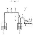
- Fig. 1 is a cross sectional view schematically showing an ink supply channel in an ink jet recording apparatus according to an embodiment of the present invention.
- Fig. 2 is a longitudinal sectional view schematically showing the structure of a filter.
- Fig. 3 is a cross-sectional view along a line A-A in Fig. 2.
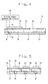
- Fig. 4 is a longitudinal sectional view schematically showing an ink jet head.
- Fig. 5 is a cross-sectional view along a line B-B in Fig. 4.
- an ink jet recording apparatus 1 has an ink jet head 2, an ink tank 3, a liquid pump 4, a filter unit 5, an ink reservoir 6 and the like. These elements are interconnected with ink pipes 7a to 7d. Note that the ink pipes 7a to 7d function as an ink supply channel to supply ink from the ink tank 3 to the ink jet head 2.
- the ink tank 3 is a tank containing ink supplied to the ink jet head 2. That is, the ink tank 3 functions as a ink reservoir containing ink.
- the ink in the ink tank 3 is supplied by driving of the liquid pump 4, via the filter unit 5 and the ink reservoir 6, to the ink jet head 2.
- As the ink oil-based liquid ink is used, and as coloring material, pigment is used.
- the filter unit 5 includes a filter F for ink filtration, and by using this filter F, removes particles in a predetermined size from the ink passing through inside.
- the filter F has a net form with polypropylene fiber or the like. In the filter F, meshes of the net become smaller toward the center, for gradually filtering ink.
- the filter unit 5 is provided with an inflow opening 5a, which is connected to the ink pipe 7b and into which the ink supplied from the liquid pump 4 flows, and an outflow opening 5b which is connected to the ink pipe 7c and from which the ink passed through the filter F goes out.
- the ink flowing from the inflow opening 5a is temporarily stored in the filter unit 5, gradually infiltrates toward the inside of the filter F, passes through the filter F and goes out from the outflow opening 5b.
- foreign materials which cause clogging in nozzles 8 and small particles as cores of bubbles occurring in the ink jet head 2 are removed.
- the ink filtered by the filter unit 5 is temporarily stored, and further, negative pressure is applied to the ink in the nozzles 8 by utilizing a water head difference "h" between the surface of ink inside the ink reservoir and the nozzles 8 provided in the ink jet head 2.
- the operation of the negative pressure prevents leakage of the ink from the nozzles 8.
- the ink reservoir 6 functions as an ink container containing ink. Note that in a case where the filter unit 5 is provided in the middle of the ink pipe 7d, the negative pressure is similarly applied to the ink in the nozzles 8.
- the ink reservoir 6 is provided in the ink jet recording apparatus 1, however, the present invention is not limited to this arrangement. For example, the ink reservoir 6 may be omitted.
- the ink jet head 2 has a nozzle plate 9 where the plural nozzles (discharge orifices) 8 are formed, and plural pressure chambers 10 which are provided in positions respectively opposing the nozzles 8 and store the ink. That is, the pressure chambers 10 function as ink containers.
- the plural pressure chambers 10 are respectively supplied with ink from a common ink chamber 11.
- a surface forming a part of the pressure chambers 10 and opposing the nozzle plate 9 is formed with a oscillation plate 12.
- the oscillation plate 12 is provided with plural piezoelectric members 13 corresponding to the respective pressure chambers 10.
- the oscillation plate 12 and the piezoelectric members 13 form an actuator.
- the piezoelectric members 13 are electrically connected to output terminal of a driving signal generation circuit 14.
- a piezoelectric device piezo device
- the present invention is not limited to the piezoelectric device.
- the oscillation plate 12, the piezoelectric members 13 and the driving signal generation circuit 14 construct driving means for discharging the ink in the pressure chambers 10 from the nozzles 8 as ink droplets.
- the common ink chamber 11 is provided with an ink supply port 15 as an opening connected to the ink pipe 7d for ink supply. Further, the plural nozzles 8 are formed in approximately straight line in the nozzle plate 9. The ink jet head 2 is arranged such that the ink is discharged from the nozzles 8 in the nozzle plate 9 as ink droplets.
- a driving signal is applied from the driving signal generation circuit 14 to the piezoelectric members 13, to deform the piezoelectric members 13, thereby the oscillation plate 12 is oscillated.
- the oscillation changes the capacities of the pressure chambers 10. In the process of increase in the capacity of the pressure chambers 10, the ink in the common ink chamber 11 is sucked by the pressure chambers 10, and in the process of decrease in the capacity of the pressure chambers 10, the ink in the pressure chambers 10 is discharged from the nozzles 8 toward the outside as ink droplets.
- the piezoelectric member 13 is used as the actuator, however, the present invention is not limited to the piezoelectric member.
- a heat generator may be used as the actuator.
- the ink jet head discharges ink from the nozzles 8 as ink droplets by boiling ink by the heat generator.
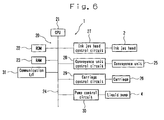
- Fig. 6 is a block diagram schematically showing electrical connection among respective elements of the ink jet recording apparatus 1.
- the ink jet recording apparatus 1 has a controller 20.
- the controller 20 has a CPU (Central Processing Unit) 21 which controls the respective elements in an intensive manner, a ROM (Read Only Memory) 22 in which various programs executed by the CPU 21 and the like are stored, a RAM (Random Access Memory) 23 which functions as a work area for the CPU 21, and the like, interconnected with a bus line 24.
- the ink jet recording apparatus 1 has a conveyance unit 25 which sequentially feeds recording media such as print sheets and conveys them in a subscanning direction, and a carriage 26 holding the ink jet head 2 and moving in a main scanning direction.
- the CPU 21 is connected to the ink jet head 2 via an ink jet head control circuit 27, to the conveyance unit 25 via a conveyance unit control circuit 28, to the carriage 26 via a carriage control circuit 29, and to the liquid pump 4 via a pump control circuit 30.
- the ink jet head control circuit 27 includes the driving signal generation circuit 14.
- the CPU 21 is connected to an external device (not shown) such as a personal computer via a communication I/F (interface) 31.
- the ink jet recording apparatus 1 having the above construction records (prints) an image on the recording medium, by moving the carriage 26 holding the ink jet head 2 from a home position (stand-by position) in the main scanning direction while conveying the recording medium in the subscanning direction by the conveyance unit 25 and drive-controlling the ink jet head 2, based on image data received from the external device via the communication I/F 31.
- the filter F of the present embodiment the filter F having the pore size of 2.2 to 5.8 ⁇ m is used. That is, as ink is quickly filtered and supplied to the ink jet head 2 without delay by using the filter F with the pore size of 2.2 to 5.8 ⁇ m, the occurrence of ink discharge failure can be reliably suppressed. That is, the ink jet head 2 can perform continuous discharging in a stable manner. Further, by using the filter F especially having a pore size of 2.5 to 3.0 ⁇ m, the occurrence of ink discharge failure can be more reliably suppressed.
- the filter F having the pore size of 2.2 to 5.8 ⁇ m is used in the ink jet recording apparatus 1. Next, the results of experiments as the ground of the selection of the above filter will be described.
- the particle diameter of the pigment as coloring material is average 100 to 400 nm. Further, as the pigment, carbon black, for example, was used.
- the printing experiment was made by continuously performing printing by the ink jet recording apparatus 1 for a predetermined period of, e.g., 10 hours, and counting the number of "omission” nozzles 8 by 1 hour. Note that upon execution of continuous printing, control was performed to move the carriage 26 (i.e., the ink jet head 2) from the home position to a predetermined position, and continuously discharge ink from all the nozzles 8 of the ink jet head 2 while conveying the recording medium by the conveyance unit 25. Further, "omission” means a status where ink is not discharged from the nozzle 8 since the nozzle 8 is clogged with ink, and as a result, the ink is not attached to the recording medium.
- the number of nozzles 8 of the ink jet head 2 is, e.g., 318.
- the omission ratio is 1.0 or lower. The printing experiments were performed for the purpose of selecting the range of the filter pore size to attain the omission ratio of 1.0 or lower.
- Fig. 7 shows the results of the printing experiments.
- Fig. 7 is a graph showing relation between filter pore size and omission ratio.
- the omission ratio (n/H) is the number of nozzles 8 (n) where omission occurred per 1 hour (1H).
- the omission ratio is 1.0 or less. It is understood that the occurrence of omission, i.e., the occurrence of ink discharge failure can be reliably suppressed. Further, in a case where the filter with pore size of particularly 2.5 to 3.0 ⁇ m is used, the omission ratio is approximately 0.5. It is understood that the occurrence of omission, i.e., the occurrence of ink discharge failure can be more reliably suppressed.
- the omission ratio is greater than 1.0. It is understood that the occurrence of omission, i.e., the occurrence of ink discharge failure can not be suppressed. Further, in a case where the filter having the pore size of 1.5 ⁇ m is used, since the pore size is the smallest, the removal of particles in ink must be improved. However, the omission ratio is 2.0, and it is understood that the occurrence of omission, i.e., the occurrence of ink discharge failure can not be reliably suppressed.
- the filter F with the pore size of 2.2 to 5.8 ⁇ m is used in the ink jet recording apparatus 1, thereby ink can be quickly filtered and supplied to the ink jet head 2 without delay. Further, as the ink is filtered with the filter F, foreign materials which cause clogging in the nozzles 8 and small particles which become cores of bubbles can be excellently removed. Even in use of oil-based pigment ink, the occurrence of ink discharge failure can be reliably suppressed. Further, by using the filter F with the pore size of 2.5 to 3.0 ⁇ m, the occurrence of ink discharge failure can be more reliably suppressed.
- the ink is oil-based pigment ink
- the ink tank 3 as the ink container contains oil-based pigment ink contains oil-based pigment ink
- the suppression of the occurrence of ink discharge failure can be further improved.
- blur or color-fade out of ink attached to a recording medium such as a print sheet can be suppressed in comparison with dye ink or the like.
- the pigment of the oil-based pigment ink is carbon black and the particle diameter of the pigment of the oil-based pigment ink is average 100 to 400 mn, the suppression of the occurrence of ink discharge failure can be further improved.
- the ink in the pressure chambers 10 was filtered with the filter F having the pore size of 2.2 to 5.8 ⁇ m. That is, foreign materials and small particles are removed from the ink, and the ink can be quickly supplied to the pressure chambers 10.
- the occurrence of ink discharge failure can be reliably suppressed.
- the occurrence of ink discharge failure can be more reliably suppressed by using the filter F with the pore size of 2.5 to 3.0 ⁇ m.
Landscapes
- Ink Jet (AREA)
- Particle Formation And Scattering Control In Inkjet Printers (AREA)
- Inks, Pencil-Leads, Or Crayons (AREA)
Abstract
Description
- The present invention relates to an ink jet recording apparatus and an ink jet head.
- Conventionally, an ink jet recording apparatus such as an ink jet printer discharges ink from nozzles as ink droplets by pressurizing ink in an pressure chamber, attaches the ink droplets to a recording medium thereby forms an image.
- In this apparatus, ink discharge failure may occur due to clogging in the nozzles or occurrence of bubbles in the pressure chamber. The ink discharge failure causes poor printing on a recording medium.
- To solve this problem, a method of providing a filter in an ink supply channel communicating with the pressure chamber has been proposed (See Japanese Published Unexamined Patent Application No. Hei 2-1324). In this method, a filter where a pore size is 0.5 µm or smaller is employed. By using this filter, foreign materials which cause clogging in the nozzles or small particles as cores of bubbles occur in the pressure chamber can be removed, thus the occurrence of discharge failure of water-based ink can be prevented.
- However, in a case where pigment ink having an particle diameter of average 100 to 400 nm is used in the ink jet recording apparatus, the filter having the pore size of 0.5 µm or smaller becomes a strong obstruction in the ink flowing through the ink supply channel and delays the speed of filtration of the ink, and as a result, delays the ink supply to the ink jet head, i.e., the pressure chamber. In such case, ink discharge failure may occur.
- Accordingly, the present invention provides an ink jet recording apparatus and an ink jet head which reliably suppress the occurrence of ink discharge failure.
- The object of the present invention is achieved by the novel ink jet recording apparatus and ink jet head.
- According to the novel ink jet recording apparatus and ink jet head of the present invention, a filter for ink filtration, with a pore size of 2.5 to 5.8 µm, is provided in an ink supply channel to supply ink to the ink jet head. The ink flowing through the ink supply channel is quickly filtered with this filter.
- A more complete appreciation of the present invention and many of the attendant advantages thereof will be readily obtained as the same becomes better understood by reference to the following detailed description when considered in connection with the accompanying drawings, wherein:
- Fig. 1 is a cross sectional view schematically showing an ink supply channel in an ink jet recording apparatus according to an embodiment of the present invention;
- Fig. 2 is a longitudinal sectional view schematically showing the structure of a filter;
- Fig. 3 is a cross-sectional view along a line A-A in Fig. 2;
- Fig. 4 is a longitudinal sectional view schematically showing an ink jet head;
- Fig. 5 is a cross-sectional view along a line B-B in Fig. 4;
- Fig. 6 is a block diagram schematically showing electrical connection among respective elements of the ink jet recording apparatus; and
- Fig. 7 is a graph showing relation between filter pore size and omission ratio.
-
- A preferred embodiment of the present invention will now be described in detail in accordance with the accompanying drawings. Fig. 1 is a cross sectional view schematically showing an ink supply channel in an ink jet recording apparatus according to an embodiment of the present invention. Fig. 2 is a longitudinal sectional view schematically showing the structure of a filter. Fig. 3 is a cross-sectional view along a line A-A in Fig. 2. Fig. 4 is a longitudinal sectional view schematically showing an ink jet head. Fig. 5 is a cross-sectional view along a line B-B in Fig. 4.
- As shown in Fig. 1, an ink
jet recording apparatus 1 has anink jet head 2, anink tank 3, aliquid pump 4, afilter unit 5, anink reservoir 6 and the like. These elements are interconnected withink pipes 7a to 7d. Note that theink pipes 7a to 7d function as an ink supply channel to supply ink from theink tank 3 to theink jet head 2. - The
ink tank 3 is a tank containing ink supplied to theink jet head 2. That is, theink tank 3 functions as a ink reservoir containing ink. The ink in theink tank 3 is supplied by driving of theliquid pump 4, via thefilter unit 5 and theink reservoir 6, to theink jet head 2. As the ink, oil-based liquid ink is used, and as coloring material, pigment is used. - As shown in Figs. 2 and 3, the
filter unit 5 includes a filter F for ink filtration, and by using this filter F, removes particles in a predetermined size from the ink passing through inside. The filter F has a net form with polypropylene fiber or the like. In the filter F, meshes of the net become smaller toward the center, for gradually filtering ink. Further, thefilter unit 5 is provided with aninflow opening 5a, which is connected to theink pipe 7b and into which the ink supplied from theliquid pump 4 flows, and an outflow opening 5b which is connected to theink pipe 7c and from which the ink passed through the filter F goes out. - Accordingly, the ink flowing from the inflow opening 5a is temporarily stored in the
filter unit 5, gradually infiltrates toward the inside of the filter F, passes through the filter F and goes out from the outflow opening 5b. In this arrangement, in the ink filtered with the filter F, foreign materials which cause clogging innozzles 8 and small particles as cores of bubbles occurring in theink jet head 2 are removed. - In the
ink reservoir 6, the ink filtered by thefilter unit 5 is temporarily stored, and further, negative pressure is applied to the ink in thenozzles 8 by utilizing a water head difference "h" between the surface of ink inside the ink reservoir and thenozzles 8 provided in theink jet head 2. The operation of the negative pressure prevents leakage of the ink from thenozzles 8. Theink reservoir 6 functions as an ink container containing ink. Note that in a case where thefilter unit 5 is provided in the middle of theink pipe 7d, the negative pressure is similarly applied to the ink in thenozzles 8. Further, in this embodiment, theink reservoir 6 is provided in the inkjet recording apparatus 1, however, the present invention is not limited to this arrangement. For example, theink reservoir 6 may be omitted. - As shown in Figs. 4 and 5, the
ink jet head 2 has anozzle plate 9 where the plural nozzles (discharge orifices) 8 are formed, andplural pressure chambers 10 which are provided in positions respectively opposing thenozzles 8 and store the ink. That is, thepressure chambers 10 function as ink containers. Theplural pressure chambers 10 are respectively supplied with ink from acommon ink chamber 11. A surface forming a part of thepressure chambers 10 and opposing thenozzle plate 9 is formed with aoscillation plate 12. Theoscillation plate 12 is provided with pluralpiezoelectric members 13 corresponding to therespective pressure chambers 10. - The
oscillation plate 12 and thepiezoelectric members 13 form an actuator. Thepiezoelectric members 13 are electrically connected to output terminal of a drivingsignal generation circuit 14. Note that as thepiezoelectric member 13, a piezoelectric device (piezo device) is employed, however, the present invention is not limited to the piezoelectric device. Theoscillation plate 12, thepiezoelectric members 13 and the drivingsignal generation circuit 14 construct driving means for discharging the ink in thepressure chambers 10 from thenozzles 8 as ink droplets. - The
common ink chamber 11 is provided with anink supply port 15 as an opening connected to theink pipe 7d for ink supply. Further, theplural nozzles 8 are formed in approximately straight line in thenozzle plate 9. Theink jet head 2 is arranged such that the ink is discharged from thenozzles 8 in thenozzle plate 9 as ink droplets. - In the
ink jet head 2 having the above construction, a driving signal is applied from the drivingsignal generation circuit 14 to thepiezoelectric members 13, to deform thepiezoelectric members 13, thereby theoscillation plate 12 is oscillated. The oscillation changes the capacities of thepressure chambers 10. In the process of increase in the capacity of thepressure chambers 10, the ink in thecommon ink chamber 11 is sucked by thepressure chambers 10, and in the process of decrease in the capacity of thepressure chambers 10, the ink in thepressure chambers 10 is discharged from thenozzles 8 toward the outside as ink droplets. - Note that in the present embodiment, the
piezoelectric member 13 is used as the actuator, however, the present invention is not limited to the piezoelectric member. For example, a heat generator may be used as the actuator. In this case, the ink jet head discharges ink from thenozzles 8 as ink droplets by boiling ink by the heat generator. - Fig. 6 is a block diagram schematically showing electrical connection among respective elements of the ink
jet recording apparatus 1. As shown in Fig. 6, the inkjet recording apparatus 1 has acontroller 20. Thecontroller 20 has a CPU (Central Processing Unit) 21 which controls the respective elements in an intensive manner, a ROM (Read Only Memory) 22 in which various programs executed by theCPU 21 and the like are stored, a RAM (Random Access Memory) 23 which functions as a work area for theCPU 21, and the like, interconnected with abus line 24. Note that the inkjet recording apparatus 1 has aconveyance unit 25 which sequentially feeds recording media such as print sheets and conveys them in a subscanning direction, and acarriage 26 holding theink jet head 2 and moving in a main scanning direction. - The
CPU 21 is connected to theink jet head 2 via an ink jethead control circuit 27, to theconveyance unit 25 via a conveyanceunit control circuit 28, to thecarriage 26 via acarriage control circuit 29, and to theliquid pump 4 via apump control circuit 30. Note that the ink jethead control circuit 27 includes the drivingsignal generation circuit 14. Further, theCPU 21 is connected to an external device (not shown) such as a personal computer via a communication I/F (interface) 31. - The ink
jet recording apparatus 1 having the above construction records (prints) an image on the recording medium, by moving thecarriage 26 holding theink jet head 2 from a home position (stand-by position) in the main scanning direction while conveying the recording medium in the subscanning direction by theconveyance unit 25 and drive-controlling theink jet head 2, based on image data received from the external device via the communication I/F 31. - As the filter F of the present embodiment, the filter F having the pore size of 2.2 to 5.8 µm is used. That is, as ink is quickly filtered and supplied to the
ink jet head 2 without delay by using the filter F with the pore size of 2.2 to 5.8 µm, the occurrence of ink discharge failure can be reliably suppressed. That is, theink jet head 2 can perform continuous discharging in a stable manner. Further, by using the filter F especially having a pore size of 2.5 to 3.0 µm, the occurrence of ink discharge failure can be more reliably suppressed. - In the present embodiment, the filter F having the pore size of 2.2 to 5.8 µm is used in the ink
jet recording apparatus 1. Next, the results of experiments as the ground of the selection of the above filter will be described. - First, 5 types of filter F having pore sizes of 1.5 µm, 2.5 µm, 3.0 µm, 5.0 µm and 8.0 µm were prepared, and the filters F were respectively attached to the above-described ink
jet recording apparatus 1 and subjected to a printing experiment. As ink used in the printing experiments, oil-based pigment ink was used. The composition of the oil-based pigment ink is as follows.Pigment 2 to 7 wt% Solvent 83 to 92 wt% Dispersant 5 wt% or less Others (additive agent, surface active agent etc.) 1 to 5 wt% - Note that the particle diameter of the pigment as coloring material is average 100 to 400 nm. Further, as the pigment, carbon black, for example, was used.
- The printing experiment was made by continuously performing printing by the ink
jet recording apparatus 1 for a predetermined period of, e.g., 10 hours, and counting the number of "omission"nozzles 8 by 1 hour. Note that upon execution of continuous printing, control was performed to move the carriage 26 (i.e., the ink jet head 2) from the home position to a predetermined position, and continuously discharge ink from all thenozzles 8 of theink jet head 2 while conveying the recording medium by theconveyance unit 25. Further, "omission" means a status where ink is not discharged from thenozzle 8 since thenozzle 8 is clogged with ink, and as a result, the ink is not attached to the recording medium. In the present embodiment, the number ofnozzles 8 of theink jet head 2 is, e.g., 318. Considering continuous and large-quantity printing, under the above-described printing condition, it is desirable that the omission ratio is 1.0 or lower. The printing experiments were performed for the purpose of selecting the range of the filter pore size to attain the omission ratio of 1.0 or lower. - Fig. 7 shows the results of the printing experiments. Fig. 7 is a graph showing relation between filter pore size and omission ratio. The omission ratio (n/H) is the number of nozzles 8 (n) where omission occurred per 1 hour (1H).
- As shown in Fig. 7, in a case where the filter with the range of pore size of 2.2 to 5.8 µm is used, the omission ratio is 1.0 or less. It is understood that the occurrence of omission, i.e., the occurrence of ink discharge failure can be reliably suppressed. Further, in a case where the filter with pore size of particularly 2.5 to 3.0 µm is used, the omission ratio is approximately 0.5. It is understood that the occurrence of omission, i.e., the occurrence of ink discharge failure can be more reliably suppressed.
- On the other hand, in a case where the filters with the pore sizes of 1.5 µm and 8.0 µm are used, the omission ratio is greater than 1.0. It is understood that the occurrence of omission, i.e., the occurrence of ink discharge failure can not be suppressed. Further, in a case where the filter having the pore size of 1.5 µm is used, since the pore size is the smallest, the removal of particles in ink must be improved. However, the omission ratio is 2.0, and it is understood that the occurrence of omission, i.e., the occurrence of ink discharge failure can not be reliably suppressed.
- Accordingly, the filter F with the pore size of 2.2 to 5.8 µm is used in the ink
jet recording apparatus 1, thereby ink can be quickly filtered and supplied to theink jet head 2 without delay. Further, as the ink is filtered with the filter F, foreign materials which cause clogging in thenozzles 8 and small particles which become cores of bubbles can be excellently removed. Even in use of oil-based pigment ink, the occurrence of ink discharge failure can be reliably suppressed. Further, by using the filter F with the pore size of 2.5 to 3.0 µm, the occurrence of ink discharge failure can be more reliably suppressed. - Note that in the present embodiment, as the ink is oil-based pigment ink, i.e., the
ink tank 3 as the ink container contains oil-based pigment ink, the suppression of the occurrence of ink discharge failure can be further improved. Further, blur or color-fade out of ink attached to a recording medium such as a print sheet can be suppressed in comparison with dye ink or the like. Further, the pigment of the oil-based pigment ink is carbon black and the particle diameter of the pigment of the oil-based pigment ink is average 100 to 400 mn, the suppression of the occurrence of ink discharge failure can be further improved. - Further, the ink in the
pressure chambers 10 was filtered with the filter F having the pore size of 2.2 to 5.8 µm. That is, foreign materials and small particles are removed from the ink, and the ink can be quickly supplied to thepressure chambers 10. Thus the occurrence of ink discharge failure can be reliably suppressed. Further, the occurrence of ink discharge failure can be more reliably suppressed by using the filter F with the pore size of 2.5 to 3.0 µm.
Claims (16)
- An ink jet recording apparatus (1), including an ink jet head (2) which discharges ink supplied from an ink container (3) containing the ink via an ink supply channel (7a to 7d) from a nozzle (8), characterized in that: a filter (F) having a pore size of 2.2 to 5.8 µm, that filters the ink flowing through the ink supply channel, is provided in the ink supply channel.
- The ink jet recording apparatus according to claim 1, wherein the ink container contains oil-based pigment ink as the ink.
- The ink jet recording apparatus according to claim 2, wherein pigment of the oil-based pigment ink is carbon black.
- The ink jet recording apparatus according to claim 2, wherein a particle diameter of the pigment of the oil-based pigment ink is average 100 to 400 nm.
- The ink jet recording apparatus according to claim 1, wherein the pore size of the filter is particularly 2.5 to 3.0 µm.
- The ink jet recording apparatus according to claim 2, wherein the pore size of the filter is particularly 2.5 to 3.0 µm.
- The ink jet recording apparatus according to claim 3, wherein the pore size of the filter is particularly 2.5 to 3.0 µm.
- The ink jet recording apparatus according to claim 4, wherein the pore size of the filter is particularly 2.5 to 3.0 µm.
- An ink jet head (2) which discharges ink in an ink chamber (10) containing the ink, from a nozzle (8) communicating with the ink chamber, characterized in that: the ink is filtered with a filter (F) having a pore size of 2.2 to 5.8 µm.
- The ink jet head according to claim 9, wherein the ink is oil-based pigment ink.
- The ink jet head according to claim 10, wherein pigment of the oil-based pigment ink is carbon black.
- The ink jet head according to claim 10, wherein a particle diameter of the pigment of the oil-based pigment ink is average 100 to 400 nm.
- The ink jet head according to claim 9, wherein the ink is filtered with the filter having the pore size of particularly 2.5 to 3.0 µm.
- The ink jet head according to claim 10, wherein the ink is filtered with the filter having the pore size of particularly 2.5 to 3.0 µm.
- The ink jet head according to claim 11, wherein the ink is filtered with the filter having the pore size of particularly 2.5 to 3.0 µm.
- The ink jet head according to claim 12, wherein the ink is filtered with the filter having the pore size of particularly 2.5 to 3.0 µm.
Applications Claiming Priority (2)
| Application Number | Priority Date | Filing Date | Title |
|---|---|---|---|
| JP2003193320 | 2003-07-08 | ||
| JP2003193320A JP2005028612A (en) | 2003-07-08 | 2003-07-08 | Inkjet recording apparatus and inkjet head |
Publications (1)
| Publication Number | Publication Date |
|---|---|
| EP1495873A1 true EP1495873A1 (en) | 2005-01-12 |
Family
ID=33447979
Family Applications (1)
| Application Number | Title | Priority Date | Filing Date |
|---|---|---|---|
| EP20040253424 Withdrawn EP1495873A1 (en) | 2003-07-08 | 2004-06-09 | Ink jet recording apparatus and ink jet head |
Country Status (3)
| Country | Link |
|---|---|
| US (1) | US7341337B2 (en) |
| EP (1) | EP1495873A1 (en) |
| JP (1) | JP2005028612A (en) |
Families Citing this family (1)
| Publication number | Priority date | Publication date | Assignee | Title |
|---|---|---|---|---|
| JP6337718B2 (en) * | 2014-09-24 | 2018-06-06 | ブラザー工業株式会社 | Printing device |
Citations (4)
| Publication number | Priority date | Publication date | Assignee | Title |
|---|---|---|---|---|
| JPH021324A (en) | 1988-06-08 | 1990-01-05 | Fujitsu Ltd | Ink jet printer |
| US5724082A (en) * | 1994-04-22 | 1998-03-03 | Specta, Inc. | Filter arrangement for ink jet head |
| US20010050017A1 (en) * | 2000-05-11 | 2001-12-13 | Fuji Photo Film Co., Ltd. | Ink jet printing process and printing apparatus |
| EP1219443A1 (en) * | 2000-12-22 | 2002-07-03 | Hewlett-Packard Company | Fluid interconnect in a replaceable ink reservoir for pigmented ink |
Family Cites Families (4)
| Publication number | Priority date | Publication date | Assignee | Title |
|---|---|---|---|---|
| US5846307A (en) * | 1996-04-19 | 1998-12-08 | Orient Chemical Industries, Ltd. | Aqueous pigment ink composition |
| JPH10151761A (en) * | 1996-11-21 | 1998-06-09 | Brother Ind Ltd | Ink jet recording device |
| JP3372833B2 (en) | 1997-07-28 | 2003-02-04 | キヤノン株式会社 | Degassing device for ink discharging device, ink discharging device, liquid discharging device, degassing device for color filter manufacturing device, color filter manufacturing device, ink discharging operation stabilizing method, and ink degassing degree stabilizing method |
| JP2002067354A (en) * | 2000-08-28 | 2002-03-05 | Toshiba Tec Corp | Inkjet printer |
-
2003
- 2003-07-08 JP JP2003193320A patent/JP2005028612A/en not_active Abandoned
-
2004
- 2004-06-09 EP EP20040253424 patent/EP1495873A1/en not_active Withdrawn
- 2004-06-30 US US10/880,901 patent/US7341337B2/en not_active Expired - Fee Related
Patent Citations (4)
| Publication number | Priority date | Publication date | Assignee | Title |
|---|---|---|---|---|
| JPH021324A (en) | 1988-06-08 | 1990-01-05 | Fujitsu Ltd | Ink jet printer |
| US5724082A (en) * | 1994-04-22 | 1998-03-03 | Specta, Inc. | Filter arrangement for ink jet head |
| US20010050017A1 (en) * | 2000-05-11 | 2001-12-13 | Fuji Photo Film Co., Ltd. | Ink jet printing process and printing apparatus |
| EP1219443A1 (en) * | 2000-12-22 | 2002-07-03 | Hewlett-Packard Company | Fluid interconnect in a replaceable ink reservoir for pigmented ink |
Also Published As
| Publication number | Publication date |
|---|---|
| US7341337B2 (en) | 2008-03-11 |
| JP2005028612A (en) | 2005-02-03 |
| US20050007429A1 (en) | 2005-01-13 |
Similar Documents
| Publication | Publication Date | Title |
|---|---|---|
| US6626528B2 (en) | Ink jet print head with bubble discharge | |
| US8141973B2 (en) | Liquid droplet ejection head and image forming apparatus having the same | |
| US6196657B1 (en) | Multi-fluidic cleaning for ink jet print heads | |
| JP4396327B2 (en) | Inkjet recording device | |
| JPH07117239A (en) | INKJET HEAD AND INKJET RECORDING DEVICE HAVING THE INKJET HEAD | |
| JP2008149594A (en) | Inkjet recording device | |
| EP1533126A1 (en) | Ink jet apparatus | |
| JPH0664183A (en) | Ink jet recording apparatus, ink jet recording head, ink jet unit, and pressure recovery method for ink jet recording apparatus | |
| US7810898B2 (en) | Liquid ejection apparatus and maintenance method for liquid ejection head | |
| JP2009285900A (en) | Line type head unit | |
| JP2002067354A (en) | Inkjet printer | |
| JPH1158776A (en) | Ink jet recording device | |
| JP4970100B2 (en) | Inkjet head | |
| JP4878514B2 (en) | Ink jet recording apparatus and cleaning method for the recording apparatus | |
| JP5067394B2 (en) | Liquid ejection device | |
| US7341337B2 (en) | Ink jet recording apparatus and ink jet head | |
| JP6035226B2 (en) | Inkjet recording device | |
| JP2011194575A (en) | Liquid jet head, liquid jet head unit, and liquid jet apparatus | |
| JP2009007458A (en) | Recording liquid and image-forming apparatus using the same | |
| JPH04212864A (en) | Ink jet recording device | |
| JP2011016906A (en) | Recording liquid | |
| JP4207551B2 (en) | Inkjet recording device | |
| JP7822535B1 (en) | Printing device and printing method | |
| JP5314853B2 (en) | Ink jet ink and ink jet recording system | |
| JP2014193555A (en) | Switching valve unit for backwash, liquid jet head and liquid jet device |
Legal Events
| Date | Code | Title | Description |
|---|---|---|---|
| PUAI | Public reference made under article 153(3) epc to a published international application that has entered the european phase |
Free format text: ORIGINAL CODE: 0009012 |
|
| 17P | Request for examination filed |
Effective date: 20040625 |
|
| AK | Designated contracting states |
Kind code of ref document: A1 Designated state(s): AT BE BG CH CY CZ DE DK EE ES FI FR GB GR HU IE IT LI LU MC NL PL PT RO SE SI SK TR |
|
| AX | Request for extension of the european patent |
Extension state: AL HR LT LV MK |
|
| AKX | Designation fees paid |
Designated state(s): DE FR GB |
|
| 17Q | First examination report despatched |
Effective date: 20120208 |
|
| R17C | First examination report despatched (corrected) |
Effective date: 20120208 |
|
| GRAP | Despatch of communication of intention to grant a patent |
Free format text: ORIGINAL CODE: EPIDOSNIGR1 |
|
| INTG | Intention to grant announced |
Effective date: 20130327 |
|
| STAA | Information on the status of an ep patent application or granted ep patent |
Free format text: STATUS: THE APPLICATION IS DEEMED TO BE WITHDRAWN |
|
| 18D | Application deemed to be withdrawn |
Effective date: 20130807 |