EP1495850B1 - Apparatus and method for producing an article made of thermoplastic and thermosetting materials - Google Patents
Apparatus and method for producing an article made of thermoplastic and thermosetting materials Download PDFInfo
- Publication number
- EP1495850B1 EP1495850B1 EP03015272A EP03015272A EP1495850B1 EP 1495850 B1 EP1495850 B1 EP 1495850B1 EP 03015272 A EP03015272 A EP 03015272A EP 03015272 A EP03015272 A EP 03015272A EP 1495850 B1 EP1495850 B1 EP 1495850B1
- Authority
- EP
- European Patent Office
- Prior art keywords
- injection moulding
- plate
- moulding
- area
- thermosetting
- Prior art date
- Legal status (The legal status is an assumption and is not a legal conclusion. Google has not performed a legal analysis and makes no representation as to the accuracy of the status listed.)
- Expired - Lifetime
Links
- 239000000463 material Substances 0.000 title claims abstract description 38
- 229920001187 thermosetting polymer Polymers 0.000 title claims abstract description 32
- 238000004519 manufacturing process Methods 0.000 title description 6
- 229920001169 thermoplastic Polymers 0.000 title description 2
- 239000004416 thermosoftening plastic Substances 0.000 title description 2
- 238000001746 injection moulding Methods 0.000 claims abstract description 35
- 238000000748 compression moulding Methods 0.000 claims abstract description 20
- 239000012815 thermoplastic material Substances 0.000 claims abstract description 17
- 238000000465 moulding Methods 0.000 claims abstract description 12
- 125000006850 spacer group Chemical group 0.000 claims abstract description 12
- 230000000149 penetrating effect Effects 0.000 claims abstract description 3
- 238000000034 method Methods 0.000 claims description 10
- 238000002347 injection Methods 0.000 claims description 9
- 239000007924 injection Substances 0.000 claims description 9
- 239000004033 plastic Substances 0.000 claims description 6
- 238000010438 heat treatment Methods 0.000 claims description 3
- 238000001816 cooling Methods 0.000 claims description 2
- 230000035515 penetration Effects 0.000 claims 1
- 238000007906 compression Methods 0.000 description 8
- 230000006835 compression Effects 0.000 description 6
- 239000011347 resin Substances 0.000 description 3
- 229920005989 resin Polymers 0.000 description 3
- 230000000295 complement effect Effects 0.000 description 2
- 238000005516 engineering process Methods 0.000 description 2
- 210000000056 organ Anatomy 0.000 description 2
- 230000003014 reinforcing effect Effects 0.000 description 2
- 238000004026 adhesive bonding Methods 0.000 description 1
- 238000004891 communication Methods 0.000 description 1
- 230000001419 dependent effect Effects 0.000 description 1
- 239000012530 fluid Substances 0.000 description 1
- 239000007769 metal material Substances 0.000 description 1
- 238000003466 welding Methods 0.000 description 1
Images


Classifications
-
- B—PERFORMING OPERATIONS; TRANSPORTING
- B29—WORKING OF PLASTICS; WORKING OF SUBSTANCES IN A PLASTIC STATE IN GENERAL
- B29C—SHAPING OR JOINING OF PLASTICS; SHAPING OF MATERIAL IN A PLASTIC STATE, NOT OTHERWISE PROVIDED FOR; AFTER-TREATMENT OF THE SHAPED PRODUCTS, e.g. REPAIRING
- B29C45/00—Injection moulding, i.e. forcing the required volume of moulding material through a nozzle into a closed mould; Apparatus therefor
- B29C45/14—Injection moulding, i.e. forcing the required volume of moulding material through a nozzle into a closed mould; Apparatus therefor incorporating preformed parts or layers, e.g. injection moulding around inserts or for coating articles
- B29C45/1418—Injection moulding, i.e. forcing the required volume of moulding material through a nozzle into a closed mould; Apparatus therefor incorporating preformed parts or layers, e.g. injection moulding around inserts or for coating articles the inserts being deformed or preformed, e.g. by the injection pressure
- B29C45/14221—Injection moulding, i.e. forcing the required volume of moulding material through a nozzle into a closed mould; Apparatus therefor incorporating preformed parts or layers, e.g. injection moulding around inserts or for coating articles the inserts being deformed or preformed, e.g. by the injection pressure by tools, e.g. cutting means
-
- B—PERFORMING OPERATIONS; TRANSPORTING
- B29—WORKING OF PLASTICS; WORKING OF SUBSTANCES IN A PLASTIC STATE IN GENERAL
- B29C—SHAPING OR JOINING OF PLASTICS; SHAPING OF MATERIAL IN A PLASTIC STATE, NOT OTHERWISE PROVIDED FOR; AFTER-TREATMENT OF THE SHAPED PRODUCTS, e.g. REPAIRING
- B29C43/00—Compression moulding, i.e. applying external pressure to flow the moulding material; Apparatus therefor
- B29C43/003—Compression moulding, i.e. applying external pressure to flow the moulding material; Apparatus therefor characterised by the choice of material
-
- B—PERFORMING OPERATIONS; TRANSPORTING
- B29—WORKING OF PLASTICS; WORKING OF SUBSTANCES IN A PLASTIC STATE IN GENERAL
- B29C—SHAPING OR JOINING OF PLASTICS; SHAPING OF MATERIAL IN A PLASTIC STATE, NOT OTHERWISE PROVIDED FOR; AFTER-TREATMENT OF THE SHAPED PRODUCTS, e.g. REPAIRING
- B29C43/00—Compression moulding, i.e. applying external pressure to flow the moulding material; Apparatus therefor
- B29C43/32—Component parts, details or accessories; Auxiliary operations
- B29C43/36—Moulds for making articles of definite length, i.e. discrete articles
-
- B—PERFORMING OPERATIONS; TRANSPORTING
- B29—WORKING OF PLASTICS; WORKING OF SUBSTANCES IN A PLASTIC STATE IN GENERAL
- B29C—SHAPING OR JOINING OF PLASTICS; SHAPING OF MATERIAL IN A PLASTIC STATE, NOT OTHERWISE PROVIDED FOR; AFTER-TREATMENT OF THE SHAPED PRODUCTS, e.g. REPAIRING
- B29C45/00—Injection moulding, i.e. forcing the required volume of moulding material through a nozzle into a closed mould; Apparatus therefor
- B29C45/17—Component parts, details or accessories; Auxiliary operations
- B29C45/26—Moulds
- B29C45/37—Mould cavity walls, i.e. the inner surface forming the mould cavity, e.g. linings
-
- B—PERFORMING OPERATIONS; TRANSPORTING
- B29—WORKING OF PLASTICS; WORKING OF SUBSTANCES IN A PLASTIC STATE IN GENERAL
- B29C—SHAPING OR JOINING OF PLASTICS; SHAPING OF MATERIAL IN A PLASTIC STATE, NOT OTHERWISE PROVIDED FOR; AFTER-TREATMENT OF THE SHAPED PRODUCTS, e.g. REPAIRING
- B29C43/00—Compression moulding, i.e. applying external pressure to flow the moulding material; Apparatus therefor
- B29C43/32—Component parts, details or accessories; Auxiliary operations
- B29C43/58—Measuring, controlling or regulating
- B29C2043/5833—Measuring, controlling or regulating movement of moulds or mould parts, e.g. opening or closing, actuating
- B29C2043/5841—Measuring, controlling or regulating movement of moulds or mould parts, e.g. opening or closing, actuating for accommodating variation in mould spacing or cavity volume during moulding
-
- B—PERFORMING OPERATIONS; TRANSPORTING
- B29—WORKING OF PLASTICS; WORKING OF SUBSTANCES IN A PLASTIC STATE IN GENERAL
- B29C—SHAPING OR JOINING OF PLASTICS; SHAPING OF MATERIAL IN A PLASTIC STATE, NOT OTHERWISE PROVIDED FOR; AFTER-TREATMENT OF THE SHAPED PRODUCTS, e.g. REPAIRING
- B29C45/00—Injection moulding, i.e. forcing the required volume of moulding material through a nozzle into a closed mould; Apparatus therefor
- B29C2045/0093—Injection moulding, i.e. forcing the required volume of moulding material through a nozzle into a closed mould; Apparatus therefor of articles provided with an attaching element
-
- B—PERFORMING OPERATIONS; TRANSPORTING
- B29—WORKING OF PLASTICS; WORKING OF SUBSTANCES IN A PLASTIC STATE IN GENERAL
- B29C—SHAPING OR JOINING OF PLASTICS; SHAPING OF MATERIAL IN A PLASTIC STATE, NOT OTHERWISE PROVIDED FOR; AFTER-TREATMENT OF THE SHAPED PRODUCTS, e.g. REPAIRING
- B29C45/00—Injection moulding, i.e. forcing the required volume of moulding material through a nozzle into a closed mould; Apparatus therefor
- B29C45/14—Injection moulding, i.e. forcing the required volume of moulding material through a nozzle into a closed mould; Apparatus therefor incorporating preformed parts or layers, e.g. injection moulding around inserts or for coating articles
- B29C45/14336—Coating a portion of the article, e.g. the edge of the article
-
- B—PERFORMING OPERATIONS; TRANSPORTING
- B29—WORKING OF PLASTICS; WORKING OF SUBSTANCES IN A PLASTIC STATE IN GENERAL
- B29L—INDEXING SCHEME ASSOCIATED WITH SUBCLASS B29C, RELATING TO PARTICULAR ARTICLES
- B29L2031/00—Other particular articles
- B29L2031/30—Vehicles, e.g. ships or aircraft, or body parts thereof
- B29L2031/3005—Body finishings
- B29L2031/3041—Trim panels
Definitions
- the present invention relates to an apparatus and a method for producing an article made of thermoplastic and thermosetting materials according to the preambles of attached claims 1,5.
- the invention was developed in particular for the production of articles formed by compression moulding of one or more plates, or sandwich, between two heated half-moulds provided with respective compression moulding surfaces.
- articles made of thermosetting material plates or sheets constituted by fibres incorporated in a thermosetting resin, initially in the viscous or plastic state, are used.
- the material in sheet or plate form is compressed between the compression moulding surfaces of two half-moulds, movable with respect to one another between an open position and a closed position.
- the thermosetting material is heated in contact with the two half-moulds, until obtaining the polymerisation and hardening of the thermosetting resin.
- thermosetting material obtained by compression moulding.
- Current technology for the production of articles for the automotive industry obtained by compression moulding a thermosetting material requires separately to produce by injection moulding reinforcing organs or fastening organs which, in a step following the thermo-compression moulding of the thermosetting material, are fastened onto one or more faces of the article made of thermosetting material by gluing, welding or by mechanical fastening means.
- thermosetting material of the plates may penetrate into the area where the thermoplastic material is to be injected. This is the case especially if an injection moulded component is to be formed on an extended surface portion of an article made of thermosetting material, due to the different behaviour of thermosetting materials with respect to thermoplastic materials during compression moulding.
- the object of the present invention therefore is to provide an improved apparatus and a method for producing an article made of thermosetting material by compression moulding and simultaneous forming of auxiliary components made of thermoplastic material by means of injection moulding.
- the reference numbers 10 and 12 schematically designate two half-moulds of a compression moulding apparatus, in particular for thermo-compression moulding of thermosetting plastic material.
- the half-moulds 10, 12 are provided with respective moulding surfaces 14, 16 and are movable between an open position shown in Figure 1 and a closed position shown in Figures 2 and 3.
- the half-moulds 10, 12 are made of metallic material and are provided with known heating means (not shown) able to bring the half-moulds to a temperature that is equal to or greater than the polymerisation temperature of the material to be moulded.
- the injection moulding area 18 communicates with the moulding surface 16 and is in fluid communication with at least an injection channel 20 connected with an apparatus for injecting plastic material under pressure (not shown).
- the injection moulding area 18 comprises a plurality of spacer elements 22 positioned in such a way as to prevent the material to be moulded by thermo-compression between the surfaces 14, 16 of the half-moulds 10, 12 from filling the injection moulding area 18.
- the injection moulding area 18 comprises a bottom surface 24 which is lowered relative to the moulding surface 16 and wherefrom project a plurality of spacer elements 22, for instance pivot shaped, preferably integral with the half-mould.
- the spacer elements 22 have respective upper support surfaces 26 which can extend above or below a plane tangential to the moulding surface 16.
- the injection moulding area 18 can be provided with seats or cavities destined to be filled with injected plastic material.
- the injection moulding area is provided with a groove 28 with V-shaped cross section whose base terminates on the bottom surface 24 of the injection moulding area 18 and whose vertex communicates with at least one injection channel 20.
- the shape of the seats or cavities provided in the injection moulding area 18 may vary on a case by case basis and it will be complementary to that of the component or of the components to be formed by injection moulding.
- one or more plates 30 of thermosetting material in the plastic state are positioned between the half-moulds 10, 12 in open position.
- a plate of thermosetting material always includes the use of two or more plates or of so-called sandwiches or agglomerates, well known in the sector of moulding components made of thermosetting material.
- the initial thickness of the plate of thermosetting material 30 is designated as S.
- the half-moulds 10, 12 are closed and the plate of thermosetting material 30 is compressed between the compression moulding surfaces 14, 16 until reaching a thickness S' which is considerably smaller than the initial thickness S.
- the spacer elements 22 serve the purpose of preventing, during the compression of the plate of thermosetting material 30 from the initial thickness S to the final thickness S2, the material constituting the plate 30 from penetrating into the injection moulding area 18 and filling the volume which is destined to be filled by injected material.
- the shape, the dimensions and the number of the spacer elements 22 may vary according to the shape and to the dimensions of the injection moulding area 18 and according to the type of material constituting the plate 30 and of the degree of compression whereto the plate is subjected.
- the plate of thermosetting material 30 heats up in contact with the half-moulds 10, 12 until the polymerisation temperature of the thermosetting resin is reached. Simultaneously or after a sufficient time to achieve conditions of partial or total hardening of the plate 30, some thermoplastic material is injected into the injection moulding area 18 through the injection channel or channels 20.
- the thermoplastic material is injected at a temperature that is considerably greater than the temperature of the half-moulds 10, 12.
- the half-moulds 10, 12 can be heated to a temperature in the order of 110-130°C whilst the thermoplastic material is injected into the injection moulding area 18 at a temperature for example in the order of 220-230°C.
- FIG. 3 shows the injection moulding step which takes place immediately or whilst the at least partially hardened thermosetting plate 30 is compressed between the half-moulds 10, 12. At the end of the injection and partial cooling and hardening of the injected thermoplastic material, the half-moulds 10, 12 are opened and the finished article is extracted.
- FIGS 5, 6 and 7 schematically show the article obtained at the end of the moulding method according to the present invention.
- Said article comprises one or more plates, sandwich or agglomerate, 30 of thermosetting material moulded by thermo-compression and at least an injection moulded component 32 integrally formed on a surface of the plate 30.
- the component 32 has a shape complementary to that of the injection moulding area 18 and, in the example shown in the figures, it comprises a base 34 wherefrom projects a rib 36 with V-shaped section. On the base 34 are formed a plurality of holes 38 in correspondence with the spacer elements 22.
Abstract
Description
- The present invention relates to an apparatus and a method for producing an article made of thermoplastic and thermosetting materials according to the preambles of attached
claims 1,5. - The invention was developed in particular for the production of articles formed by compression moulding of one or more plates, or sandwich, between two heated half-moulds provided with respective compression moulding surfaces. For the production of articles made of thermosetting material, plates or sheets constituted by fibres incorporated in a thermosetting resin, initially in the viscous or plastic state, are used. The material in sheet or plate form is compressed between the compression moulding surfaces of two half-moulds, movable with respect to one another between an open position and a closed position. During compression in the mould, the thermosetting material is heated in contact with the two half-moulds, until obtaining the polymerisation and hardening of the thermosetting resin.
- In many technical sectors, in particular in the automotive industry, there is a need to provide reinforcing areas or fastening materials made of thermoplastic material on one or more faces of an article made of thermosetting material obtained by compression moulding. Current technology for the production of articles for the automotive industry obtained by compression moulding a thermosetting material, requires separately to produce by injection moulding reinforcing organs or fastening organs which, in a step following the thermo-compression moulding of the thermosetting material, are fastened onto one or more faces of the article made of thermosetting material by gluing, welding or by mechanical fastening means.
- In the sector of moulding of articles made of compression moulded thermoplastic material, a method has already been proposed for forming by means of injection moulding a component anchored onto a surface of a plate made of thermoplastic material whilst said plate is compression moulded between two mutually facing surfaces of two half-moulds. For instance, the document
EP-A-1153725 by the same Applicant discloses a method and an apparatus which provide an injection moulding cavity obtained in one of the two half-moulds and which terminates on the compression moulding surface of the same half-moulds by means of a restricted section to prevent the injection moulded material from damaging the compression moulded plate. - However, this technology cannot be immediately transferred to the sector of thermo-compression moulding of articles made of thermosetting materials. During compression moulding the thermosetting material of the plates may penetrate into the area where the thermoplastic material is to be injected. This is the case especially if an injection moulded component is to be formed on an extended surface portion of an article made of thermosetting material, due to the different behaviour of thermosetting materials with respect to thermoplastic materials during compression moulding.
- The object of the present invention therefore is to provide an improved apparatus and a method for producing an article made of thermosetting material by compression moulding and simultaneous forming of auxiliary components made of thermoplastic material by means of injection moulding.
- According to the present invention, said object is achieved by an apparatus and by a method having the characteristics set out in the
claims 1, 5. Preferred embodiments are disclosed in the dependent claims. - The present invention shall now be described in detail with reference to the accompanying drawings, provided purely by way of non limiting example, in which:
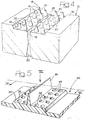
- Figures 1 through 3 are schematic views showing three steps of a method according to the present invention,
- Figure 4 is a schematic perspective view of the part designated by the arrow IV in Figure 1,
- Figure 5 is a schematic perspective view of an article obtained with the method according to the invention, and
- Figures 6 and 7 are a section and a plan view according to the line VI-VI and according to the arrow VII of Figure 5.
- With reference to Figures 1 through 3, the
reference numbers moulds respective moulding surfaces moulds - With reference in particular to Figure 4, in at least one of the two half-
moulds mould 12, is obtained at least an injection moulding area designated as 18. Theinjection moulding area 18 communicates with themoulding surface 16 and is in fluid communication with at least aninjection channel 20 connected with an apparatus for injecting plastic material under pressure (not shown). According to the present invention, theinjection moulding area 18 comprises a plurality ofspacer elements 22 positioned in such a way as to prevent the material to be moulded by thermo-compression between thesurfaces moulds injection moulding area 18. In the embodiment illustrated purely by way of example in the figures, theinjection moulding area 18 comprises abottom surface 24 which is lowered relative to themoulding surface 16 and wherefrom project a plurality ofspacer elements 22, for instance pivot shaped, preferably integral with the half-mould. Thespacer elements 22 have respectiveupper support surfaces 26 which can extend above or below a plane tangential to themoulding surface 16. Theinjection moulding area 18 can be provided with seats or cavities destined to be filled with injected plastic material. In the example illustrated in the figures, the injection moulding area is provided with agroove 28 with V-shaped cross section whose base terminates on thebottom surface 24 of theinjection moulding area 18 and whose vertex communicates with at least oneinjection channel 20. The shape of the seats or cavities provided in theinjection moulding area 18 may vary on a case by case basis and it will be complementary to that of the component or of the components to be formed by injection moulding. - With reference to Figure 1, in the first operative step of the method according to the invention one or
more plates 30 of thermosetting material in the plastic state are positioned between the half-moulds thermosetting material 30 is designated as S. - In a second operative step schematically illustrated in Figure 2, the half-
moulds thermosetting material 30 is compressed between thecompression moulding surfaces spacer elements 22 serve the purpose of preventing, during the compression of the plate ofthermosetting material 30 from the initial thickness S to the final thickness S2, the material constituting theplate 30 from penetrating into theinjection moulding area 18 and filling the volume which is destined to be filled by injected material. The shape, the dimensions and the number of thespacer elements 22 may vary according to the shape and to the dimensions of theinjection moulding area 18 and according to the type of material constituting theplate 30 and of the degree of compression whereto the plate is subjected. - In the operative step schematically shown in Figure 2, the plate of
thermosetting material 30 heats up in contact with the half-moulds plate 30, some thermoplastic material is injected into theinjection moulding area 18 through the injection channel orchannels 20. The thermoplastic material is injected at a temperature that is considerably greater than the temperature of the half-moulds moulds injection moulding area 18 at a temperature for example in the order of 220-230°C. The material injected into theinjection moulding area 18 cools in contact with the walls which define theinjection moulding area 18 to a temperature that allows to obtain a sufficient compactness of the injection plastic material, such that it will maintain its own shape. Figure 3 shows the injection moulding step which takes place immediately or whilst the at least partially hardenedthermosetting plate 30 is compressed between the half-moulds moulds - Figures 5, 6 and 7 schematically show the article obtained at the end of the moulding method according to the present invention. Said article comprises one or more plates, sandwich or agglomerate, 30 of thermosetting material moulded by thermo-compression and at least an injection moulded
component 32 integrally formed on a surface of theplate 30. Thecomponent 32 has a shape complementary to that of theinjection moulding area 18 and, in the example shown in the figures, it comprises abase 34 wherefrom projects arib 36 with V-shaped section. On thebase 34 are formed a plurality ofholes 38 in correspondence with thespacer elements 22.
Claims (7)
- An apparatus for moulding an article made of thermosetting and thermoplastic material, comprising:- a first and a second half-mould (10, 12) provided with respective compression moulding surfaces (14, 16) suitable to compress between them one or more plates (30), sandwich or agglomerate, made of mouldable thermosetting material, and- at least one injection moulding area (18) comprising a chamber communicating with at least one of said compression moulding surfaces (14, 16), in which, in use, thermoplastic material is injected,characterised in that it comprises spacer means (22) provided in said injection moulding area (18), said spacer means (22) extending inside said chamber and positioned in such a way as to prevent said plate (30) from penetrating into said injection moulding area (18) when it is compressed between said compression moulding surfaces (14, 16).
- An apparatus as claimed in claim 1, characterised in that said spacer means are integral with one of said half-moulds (10, 12) and project from at least a surface (24) of said injection moulding area (18).
- An apparatus as claimed in claim 1, characterised in that said spacer means comprise a plurality of pivot shaped elements (22) projecting from a bottom surface (24) of said injection moulding area (18).
- An apparatus as claimed in claim 3, characterised in that said projecting elements (22) have respective support surfaces (26) destined to come in contact with a surface of said plate (30).
- A method for moulding an article made of thermosetting and the thermoplastic material, comprising the steps of:- compressing a plate of mouldable thermosetting material between two mutually opposite moulding surfaces (14, 16),- providing at least one injection moulding area (18) comprising a chamber communicating with at least one of said moulding surfaces (14, 16), and- injecting thermoplastic material in contact with a surface portion of said plate (30) into said chamber of said injection moulding area (18),characterised in that it comprises the step of providing spacer means (22) in said injection moulding area (18), extending inside said chamber and positioned in such a way as to prevent the penetration of said plate (30) into said injection moulding area (18).
- A method as claimed in claim 5, characterised in that it comprises the step of heating said plate (30) in contact with said half-shells (10, 12) until reaching a polymerisation temperature of the plastic material constituting said plate (30).
- A method as claimed in claim 6, characterised in that it comprises the step of heating the thermoplastic material before its injection into the aforesaid injection moulding area (18) and cooling said thermoplastic material in contact with said half-moulds (10, 12) down to a temperature of partial hardening.
Priority Applications (4)
| Application Number | Priority Date | Filing Date | Title |
|---|---|---|---|
| ES03015272T ES2291566T3 (en) | 2003-07-07 | 2003-07-07 | APPARATUS AND PROCEDURE TO PRODUCE A MANUFACTURED ARTICLE OF THERMOPLASTIC AND THERMOENDURECIBLE MATERIALS. |
| EP03015272A EP1495850B1 (en) | 2003-07-07 | 2003-07-07 | Apparatus and method for producing an article made of thermoplastic and thermosetting materials |
| AT03015272T ATE369960T1 (en) | 2003-07-07 | 2003-07-07 | DEVICE AND METHOD FOR PRODUCING OBJECTS FROM THERMOPLASTIC AND THERMOSET PLASTICS |
| DE60315625T DE60315625T2 (en) | 2003-07-07 | 2003-07-07 | Apparatus and method for producing articles of thermoplastic and thermosetting plastics |
Applications Claiming Priority (1)
| Application Number | Priority Date | Filing Date | Title |
|---|---|---|---|
| EP03015272A EP1495850B1 (en) | 2003-07-07 | 2003-07-07 | Apparatus and method for producing an article made of thermoplastic and thermosetting materials |
Publications (2)
| Publication Number | Publication Date |
|---|---|
| EP1495850A1 EP1495850A1 (en) | 2005-01-12 |
| EP1495850B1 true EP1495850B1 (en) | 2007-08-15 |
Family
ID=33442743
Family Applications (1)
| Application Number | Title | Priority Date | Filing Date |
|---|---|---|---|
| EP03015272A Expired - Lifetime EP1495850B1 (en) | 2003-07-07 | 2003-07-07 | Apparatus and method for producing an article made of thermoplastic and thermosetting materials |
Country Status (4)
| Country | Link |
|---|---|
| EP (1) | EP1495850B1 (en) |
| AT (1) | ATE369960T1 (en) |
| DE (1) | DE60315625T2 (en) |
| ES (1) | ES2291566T3 (en) |
Cited By (1)
| Publication number | Priority date | Publication date | Assignee | Title |
|---|---|---|---|---|
| DE102012106936A1 (en) | 2012-07-30 | 2014-01-30 | International Automotive Components Group Gmbh | Integrated contact heating for thermoplastic bonded mats in the injection mold |
Families Citing this family (1)
| Publication number | Priority date | Publication date | Assignee | Title |
|---|---|---|---|---|
| US7740910B2 (en) | 2006-11-27 | 2010-06-22 | Lockheed Martin Corporation | Method for epoxy application control overpresses |
Family Cites Families (7)
| Publication number | Priority date | Publication date | Assignee | Title |
|---|---|---|---|---|
| US4088729A (en) * | 1971-01-22 | 1978-05-09 | Sherman William F | Method of bonding a phenol-based thermoplastic resin to a cured and molded thermoset phenolic plastic |
| US4418031A (en) * | 1981-04-06 | 1983-11-29 | Van Dresser Corporation | Moldable fibrous mat and method of making the same |
| DE3933416A1 (en) * | 1989-10-06 | 1991-04-18 | Daimler Benz Ag | METHOD FOR LOCALLY DEFINED, FIXING ATTACHMENT OF PLASTIC SMALL PARTS ON NATURAL FIBER OR COMPOSED PRESSURE COMPONENTS THAT ARE BASED ON GLUED OR RESIN-BASED |
| CA2169015A1 (en) * | 1996-02-07 | 1997-08-08 | Michael Munger | Compression - injection molding apparatus |
| DE19733598C2 (en) * | 1997-07-29 | 1999-06-10 | Guenter Tauber | Process for the production of a thin-walled, injection molded plastic part |
| IT1320350B1 (en) * | 2000-05-12 | 2003-11-26 | Crs Srl Ct Ricerche & Sperimen | PROCESS AND EQUIPMENT FOR THERMOCOMPRESSION MOLDING OF ARTICLES OF THERMOPLASTIC MATERIAL. |
| FR2820072B1 (en) * | 2001-01-29 | 2003-10-17 | Mediterranee Const Ind | MECHANICAL PART IN THE SHAPE OF A REINFORCED ELASTOMER SHEET, ITS MANUFACTURING METHOD AND MOLD FOR SAID MANUFACTURING |
-
2003
- 2003-07-07 AT AT03015272T patent/ATE369960T1/en not_active IP Right Cessation
- 2003-07-07 ES ES03015272T patent/ES2291566T3/en not_active Expired - Lifetime
- 2003-07-07 DE DE60315625T patent/DE60315625T2/en not_active Expired - Lifetime
- 2003-07-07 EP EP03015272A patent/EP1495850B1/en not_active Expired - Lifetime
Non-Patent Citations (1)
| Title |
|---|
| None * |
Cited By (3)
| Publication number | Priority date | Publication date | Assignee | Title |
|---|---|---|---|---|
| DE102012106936A1 (en) | 2012-07-30 | 2014-01-30 | International Automotive Components Group Gmbh | Integrated contact heating for thermoplastic bonded mats in the injection mold |
| EP2692504A1 (en) | 2012-07-30 | 2014-02-05 | International Automotive Components Group GmbH | Integrated contact heating for thermoplastically bonded mats in an injection moulding tool |
| US9713888B2 (en) | 2012-07-30 | 2017-07-25 | International Automotive Components Group Gmbh | Integrated contact heating for thermoplastically bound mats in an injection-molding tool |
Also Published As
| Publication number | Publication date |
|---|---|
| ES2291566T3 (en) | 2008-03-01 |
| ATE369960T1 (en) | 2007-09-15 |
| EP1495850A1 (en) | 2005-01-12 |
| DE60315625D1 (en) | 2007-09-27 |
| DE60315625T2 (en) | 2008-05-08 |
Similar Documents
| Publication | Publication Date | Title |
|---|---|---|
| JP3698517B2 (en) | Composite material molding equipment | |
| EP0687548A2 (en) | Process for producing fiber-reinforced thermoplastic resin molded article and mold used for producing same | |
| US8178032B2 (en) | Manufacture of composites by a flexible injection process using a double or multiple cavity mold | |
| US5759464A (en) | Methods for manufacturing multilayer moldings | |
| CA2477149C (en) | Method for expansion injection molding | |
| KR900007327B1 (en) | Manufacture of synthetic resin product having porous elastic member | |
| US20070278713A1 (en) | Method for producing a composite part by injection moulding, injection compression moulding or back compression moulding of a plastic material | |
| WO2001096096A1 (en) | Fluid compression of injection molded plastic materials | |
| CN104349880A (en) | Molding method for fiber-reinforced plastic structure, and vehicle wheel | |
| CN103269841A (en) | Method and device for producing fibre-einforced interior trim components comprising attachment elements for motor vehicles | |
| EP1153725B1 (en) | Process and equipment for hot moulding of articles made of thermoplastic material | |
| KR101742323B1 (en) | Injection-moulded article having a field of hooks obtained by moulding | |
| US7186105B2 (en) | Apparatus and method for producing an article made of thermoplastic and thermosetting materials | |
| CN108778661B (en) | Method and apparatus for press-molding FRP sheet, and FRP molded article | |
| US5863365A (en) | Method of manufacturing composite articles | |
| CN102300691B (en) | For being manufactured the device of composite material component by resin transfer molding | |
| EP1495850B1 (en) | Apparatus and method for producing an article made of thermoplastic and thermosetting materials | |
| US20060147697A1 (en) | Method for producing rear-injected plastic moulded parts | |
| US20070290411A1 (en) | Method For Producing A Composite Part By Injection Moulding, Injection Compression Moulding Or Back Compression Moulding Of A Plastic Material | |
| US6602460B2 (en) | Gas injected compression molding | |
| CN111542423B (en) | Method for manufacturing a composite component comprising a core and at least one skin region | |
| JP6915379B2 (en) | Composite material molding method and molding equipment | |
| JPS6319215A (en) | Method for compression molding of resin molded article | |
| CN108778660B (en) | FRP sheet compression molding method and device, and FRP molded product | |
| US20230294337A1 (en) | Method for Manufacturing an Articular Prosthesis Implant Using a Ceramic Imprint |
Legal Events
| Date | Code | Title | Description |
|---|---|---|---|
| PUAI | Public reference made under article 153(3) epc to a published international application that has entered the european phase |
Free format text: ORIGINAL CODE: 0009012 |
|
| AK | Designated contracting states |
Kind code of ref document: A1 Designated state(s): AT BE BG CH CY CZ DE DK EE ES FI FR GB GR HU IE IT LI LU MC NL PT RO SE SI SK TR |
|
| AX | Request for extension of the european patent |
Extension state: AL LT LV MK |
|
| 17P | Request for examination filed |
Effective date: 20050712 |
|
| AKX | Designation fees paid |
Designated state(s): AT BE BG CH CY CZ DE DK EE ES FI FR GB GR HU IE IT LI LU MC NL PT RO SE SI SK TR |
|
| GRAP | Despatch of communication of intention to grant a patent |
Free format text: ORIGINAL CODE: EPIDOSNIGR1 |
|
| GRAS | Grant fee paid |
Free format text: ORIGINAL CODE: EPIDOSNIGR3 |
|
| GRAA | (expected) grant |
Free format text: ORIGINAL CODE: 0009210 |
|
| AK | Designated contracting states |
Kind code of ref document: B1 Designated state(s): AT BE BG CH CY CZ DE DK EE ES FI FR GB GR HU IE IT LI LU MC NL PT RO SE SI SK TR |
|
| REG | Reference to a national code |
Ref country code: GB Ref legal event code: FG4D |
|
| REG | Reference to a national code |
Ref country code: CH Ref legal event code: EP |
|
| REG | Reference to a national code |
Ref country code: IE Ref legal event code: FG4D |
|
| REF | Corresponds to: |
Ref document number: 60315625 Country of ref document: DE Date of ref document: 20070927 Kind code of ref document: P |
|
| ET | Fr: translation filed | ||
| PG25 | Lapsed in a contracting state [announced via postgrant information from national office to epo] |
Ref country code: NL Free format text: LAPSE BECAUSE OF FAILURE TO SUBMIT A TRANSLATION OF THE DESCRIPTION OR TO PAY THE FEE WITHIN THE PRESCRIBED TIME-LIMIT Effective date: 20070815 Ref country code: FI Free format text: LAPSE BECAUSE OF FAILURE TO SUBMIT A TRANSLATION OF THE DESCRIPTION OR TO PAY THE FEE WITHIN THE PRESCRIBED TIME-LIMIT Effective date: 20070815 Ref country code: BG Free format text: LAPSE BECAUSE OF FAILURE TO SUBMIT A TRANSLATION OF THE DESCRIPTION OR TO PAY THE FEE WITHIN THE PRESCRIBED TIME-LIMIT Effective date: 20071115 |
|
| NLV1 | Nl: lapsed or annulled due to failure to fulfill the requirements of art. 29p and 29m of the patents act | ||
| PG25 | Lapsed in a contracting state [announced via postgrant information from national office to epo] |
Ref country code: LI Free format text: LAPSE BECAUSE OF FAILURE TO SUBMIT A TRANSLATION OF THE DESCRIPTION OR TO PAY THE FEE WITHIN THE PRESCRIBED TIME-LIMIT Effective date: 20070815 Ref country code: CH Free format text: LAPSE BECAUSE OF FAILURE TO SUBMIT A TRANSLATION OF THE DESCRIPTION OR TO PAY THE FEE WITHIN THE PRESCRIBED TIME-LIMIT Effective date: 20070815 Ref country code: AT Free format text: LAPSE BECAUSE OF FAILURE TO SUBMIT A TRANSLATION OF THE DESCRIPTION OR TO PAY THE FEE WITHIN THE PRESCRIBED TIME-LIMIT Effective date: 20070815 |
|
| REG | Reference to a national code |
Ref country code: CH Ref legal event code: PL |
|
| REG | Reference to a national code |
Ref country code: ES Ref legal event code: FG2A Ref document number: 2291566 Country of ref document: ES Kind code of ref document: T3 |
|
| PG25 | Lapsed in a contracting state [announced via postgrant information from national office to epo] |
Ref country code: BE Free format text: LAPSE BECAUSE OF FAILURE TO SUBMIT A TRANSLATION OF THE DESCRIPTION OR TO PAY THE FEE WITHIN THE PRESCRIBED TIME-LIMIT Effective date: 20070815 |
|
| PG25 | Lapsed in a contracting state [announced via postgrant information from national office to epo] |
Ref country code: DK Free format text: LAPSE BECAUSE OF FAILURE TO SUBMIT A TRANSLATION OF THE DESCRIPTION OR TO PAY THE FEE WITHIN THE PRESCRIBED TIME-LIMIT Effective date: 20070815 Ref country code: GR Free format text: LAPSE BECAUSE OF FAILURE TO SUBMIT A TRANSLATION OF THE DESCRIPTION OR TO PAY THE FEE WITHIN THE PRESCRIBED TIME-LIMIT Effective date: 20071116 |
|
| PG25 | Lapsed in a contracting state [announced via postgrant information from national office to epo] |
Ref country code: CZ Free format text: LAPSE BECAUSE OF FAILURE TO SUBMIT A TRANSLATION OF THE DESCRIPTION OR TO PAY THE FEE WITHIN THE PRESCRIBED TIME-LIMIT Effective date: 20070815 Ref country code: SK Free format text: LAPSE BECAUSE OF FAILURE TO SUBMIT A TRANSLATION OF THE DESCRIPTION OR TO PAY THE FEE WITHIN THE PRESCRIBED TIME-LIMIT Effective date: 20070815 Ref country code: PT Free format text: LAPSE BECAUSE OF FAILURE TO SUBMIT A TRANSLATION OF THE DESCRIPTION OR TO PAY THE FEE WITHIN THE PRESCRIBED TIME-LIMIT Effective date: 20080115 |
|
| PLBE | No opposition filed within time limit |
Free format text: ORIGINAL CODE: 0009261 |
|
| STAA | Information on the status of an ep patent application or granted ep patent |
Free format text: STATUS: NO OPPOSITION FILED WITHIN TIME LIMIT |
|
| PG25 | Lapsed in a contracting state [announced via postgrant information from national office to epo] |
Ref country code: RO Free format text: LAPSE BECAUSE OF FAILURE TO SUBMIT A TRANSLATION OF THE DESCRIPTION OR TO PAY THE FEE WITHIN THE PRESCRIBED TIME-LIMIT Effective date: 20070815 Ref country code: SE Free format text: LAPSE BECAUSE OF FAILURE TO SUBMIT A TRANSLATION OF THE DESCRIPTION OR TO PAY THE FEE WITHIN THE PRESCRIBED TIME-LIMIT Effective date: 20071115 |
|
| 26N | No opposition filed |
Effective date: 20080516 |
|
| PG25 | Lapsed in a contracting state [announced via postgrant information from national office to epo] |
Ref country code: MC Free format text: LAPSE BECAUSE OF NON-PAYMENT OF DUE FEES Effective date: 20080731 |
|
| PG25 | Lapsed in a contracting state [announced via postgrant information from national office to epo] |
Ref country code: EE Free format text: LAPSE BECAUSE OF FAILURE TO SUBMIT A TRANSLATION OF THE DESCRIPTION OR TO PAY THE FEE WITHIN THE PRESCRIBED TIME-LIMIT Effective date: 20070815 |
|
| PG25 | Lapsed in a contracting state [announced via postgrant information from national office to epo] |
Ref country code: SI Free format text: LAPSE BECAUSE OF FAILURE TO SUBMIT A TRANSLATION OF THE DESCRIPTION OR TO PAY THE FEE WITHIN THE PRESCRIBED TIME-LIMIT Effective date: 20070815 |
|
| PG25 | Lapsed in a contracting state [announced via postgrant information from national office to epo] |
Ref country code: IE Free format text: LAPSE BECAUSE OF NON-PAYMENT OF DUE FEES Effective date: 20080707 Ref country code: CY Free format text: LAPSE BECAUSE OF FAILURE TO SUBMIT A TRANSLATION OF THE DESCRIPTION OR TO PAY THE FEE WITHIN THE PRESCRIBED TIME-LIMIT Effective date: 20070815 |
|
| PG25 | Lapsed in a contracting state [announced via postgrant information from national office to epo] |
Ref country code: LU Free format text: LAPSE BECAUSE OF NON-PAYMENT OF DUE FEES Effective date: 20080707 Ref country code: HU Free format text: LAPSE BECAUSE OF FAILURE TO SUBMIT A TRANSLATION OF THE DESCRIPTION OR TO PAY THE FEE WITHIN THE PRESCRIBED TIME-LIMIT Effective date: 20080216 |
|
| PG25 | Lapsed in a contracting state [announced via postgrant information from national office to epo] |
Ref country code: TR Free format text: LAPSE BECAUSE OF FAILURE TO SUBMIT A TRANSLATION OF THE DESCRIPTION OR TO PAY THE FEE WITHIN THE PRESCRIBED TIME-LIMIT Effective date: 20070815 |
|
| REG | Reference to a national code |
Ref country code: DE Ref legal event code: R082 Ref document number: 60315625 Country of ref document: DE Representative=s name: MUELLER & SCHUBERT PATENTANWAELTE, DE |
|
| REG | Reference to a national code |
Ref country code: FR Ref legal event code: PLFP Year of fee payment: 14 |
|
| REG | Reference to a national code |
Ref country code: FR Ref legal event code: PLFP Year of fee payment: 15 |
|
| PGFP | Annual fee paid to national office [announced via postgrant information from national office to epo] |
Ref country code: GB Payment date: 20170714 Year of fee payment: 15 Ref country code: DE Payment date: 20170725 Year of fee payment: 15 Ref country code: FR Payment date: 20170725 Year of fee payment: 15 Ref country code: IT Payment date: 20170703 Year of fee payment: 15 Ref country code: ES Payment date: 20170801 Year of fee payment: 15 |
|
| REG | Reference to a national code |
Ref country code: DE Ref legal event code: R119 Ref document number: 60315625 Country of ref document: DE |
|
| GBPC | Gb: european patent ceased through non-payment of renewal fee |
Effective date: 20180707 |
|
| PG25 | Lapsed in a contracting state [announced via postgrant information from national office to epo] |
Ref country code: DE Free format text: LAPSE BECAUSE OF NON-PAYMENT OF DUE FEES Effective date: 20190201 Ref country code: GB Free format text: LAPSE BECAUSE OF NON-PAYMENT OF DUE FEES Effective date: 20180707 Ref country code: FR Free format text: LAPSE BECAUSE OF NON-PAYMENT OF DUE FEES Effective date: 20180731 |
|
| PG25 | Lapsed in a contracting state [announced via postgrant information from national office to epo] |
Ref country code: IT Free format text: LAPSE BECAUSE OF NON-PAYMENT OF DUE FEES Effective date: 20180707 |
|
| REG | Reference to a national code |
Ref country code: ES Ref legal event code: FD2A Effective date: 20190917 |
|
| PG25 | Lapsed in a contracting state [announced via postgrant information from national office to epo] |
Ref country code: ES Free format text: LAPSE BECAUSE OF NON-PAYMENT OF DUE FEES Effective date: 20180708 |