EP1495533B1 - Stromumsetzer - Google Patents
Stromumsetzer Download PDFInfo
- Publication number
- EP1495533B1 EP1495533B1 EP03746857A EP03746857A EP1495533B1 EP 1495533 B1 EP1495533 B1 EP 1495533B1 EP 03746857 A EP03746857 A EP 03746857A EP 03746857 A EP03746857 A EP 03746857A EP 1495533 B1 EP1495533 B1 EP 1495533B1
- Authority
- EP
- European Patent Office
- Prior art keywords
- switch
- matrix
- commutation
- converter
- delay operations
- Prior art date
- Legal status (The legal status is an assumption and is not a legal conclusion. Google has not performed a legal analysis and makes no representation as to the accuracy of the status listed.)
- Expired - Lifetime
Links
- 239000011159 matrix material Substances 0.000 claims abstract description 33
- 238000000034 method Methods 0.000 claims description 29
- 239000004065 semiconductor Substances 0.000 claims description 8
- 238000013459 approach Methods 0.000 claims description 5
- 238000004590 computer program Methods 0.000 claims description 5
- 230000006870 function Effects 0.000 claims description 5
- 230000000694 effects Effects 0.000 claims description 4
- 230000009467 reduction Effects 0.000 claims description 4
- 230000000977 initiatory effect Effects 0.000 claims description 2
- 241001481828 Glyptocephalus cynoglossus Species 0.000 claims 1
- 230000004913 activation Effects 0.000 claims 1
- 230000008901 benefit Effects 0.000 abstract description 4
- 239000003990 capacitor Substances 0.000 abstract description 4
- 230000006698 induction Effects 0.000 abstract description 4
- 238000012360 testing method Methods 0.000 description 13
- 239000000835 fiber Substances 0.000 description 10
- 210000004027 cell Anatomy 0.000 description 8
- 230000008569 process Effects 0.000 description 7
- 101100171060 Caenorhabditis elegans div-1 gene Proteins 0.000 description 6
- 238000006243 chemical reaction Methods 0.000 description 5
- 102100021934 Cyclin-D1-binding protein 1 Human genes 0.000 description 4
- 101000897488 Homo sapiens Cyclin-D1-binding protein 1 Proteins 0.000 description 4
- 101000651236 Homo sapiens NCK-interacting protein with SH3 domain Proteins 0.000 description 4
- 101100387347 Saccharomyces cerevisiae (strain ATCC 204508 / S288c) DIP5 gene Proteins 0.000 description 3
- 230000002093 peripheral effect Effects 0.000 description 3
- 101150061050 CIN1 gene Proteins 0.000 description 2
- 102100037922 Disco-interacting protein 2 homolog A Human genes 0.000 description 2
- 101000805876 Homo sapiens Disco-interacting protein 2 homolog A Proteins 0.000 description 2
- 101000955093 Homo sapiens WD repeat-containing protein 3 Proteins 0.000 description 2
- 101150005988 cin2 gene Proteins 0.000 description 2
- 230000001934 delay Effects 0.000 description 2
- 238000005516 engineering process Methods 0.000 description 2
- 238000010304 firing Methods 0.000 description 2
- 238000003032 molecular docking Methods 0.000 description 2
- 210000003771 C cell Anatomy 0.000 description 1
- XUIMIQQOPSSXEZ-UHFFFAOYSA-N Silicon Chemical compound [Si] XUIMIQQOPSSXEZ-UHFFFAOYSA-N 0.000 description 1
- 210000003719 b-lymphocyte Anatomy 0.000 description 1
- 230000003750 conditioning effect Effects 0.000 description 1
- 238000013461 design Methods 0.000 description 1
- 238000001514 detection method Methods 0.000 description 1
- 238000011161 development Methods 0.000 description 1
- 238000010586 diagram Methods 0.000 description 1
- 238000011038 discontinuous diafiltration by volume reduction Methods 0.000 description 1
- 230000008030 elimination Effects 0.000 description 1
- 238000003379 elimination reaction Methods 0.000 description 1
- 238000001914 filtration Methods 0.000 description 1
- 230000036039 immunity Effects 0.000 description 1
- 238000005259 measurement Methods 0.000 description 1
- 238000012986 modification Methods 0.000 description 1
- 230000004048 modification Effects 0.000 description 1
- 229910052710 silicon Inorganic materials 0.000 description 1
- 239000010703 silicon Substances 0.000 description 1
Images


Classifications
-
- H—ELECTRICITY
- H02—GENERATION; CONVERSION OR DISTRIBUTION OF ELECTRIC POWER
- H02M—APPARATUS FOR CONVERSION BETWEEN AC AND AC, BETWEEN AC AND DC, OR BETWEEN DC AND DC, AND FOR USE WITH MAINS OR SIMILAR POWER SUPPLY SYSTEMS; CONVERSION OF DC OR AC INPUT POWER INTO SURGE OUTPUT POWER; CONTROL OR REGULATION THEREOF
- H02M5/00—Conversion of AC power input into AC power output, e.g. for change of voltage, for change of frequency, for change of number of phases
- H02M5/02—Conversion of AC power input into AC power output, e.g. for change of voltage, for change of frequency, for change of number of phases without intermediate conversion into DC
- H02M5/04—Conversion of AC power input into AC power output, e.g. for change of voltage, for change of frequency, for change of number of phases without intermediate conversion into DC by static converters
- H02M5/22—Conversion of AC power input into AC power output, e.g. for change of voltage, for change of frequency, for change of number of phases without intermediate conversion into DC by static converters using discharge tubes with control electrode or semiconductor devices with control electrode
- H02M5/275—Conversion of AC power input into AC power output, e.g. for change of voltage, for change of frequency, for change of number of phases without intermediate conversion into DC by static converters using discharge tubes with control electrode or semiconductor devices with control electrode using devices of a triode or transistor type requiring continuous application of a control signal
- H02M5/293—Conversion of AC power input into AC power output, e.g. for change of voltage, for change of frequency, for change of number of phases without intermediate conversion into DC by static converters using discharge tubes with control electrode or semiconductor devices with control electrode using devices of a triode or transistor type requiring continuous application of a control signal using semiconductor devices only
Definitions
- the present invention relates to power converters and to methods of power conversion.
- the commutation time for a converter is reduced compared to present conventional equipment.
- Such commutation times can be reduced to such levels as to approach or reach zero, and can even be slightly negative up to the total of the turn-off and turn-off delay times of the switching devices used.
- the turn-off signal is sent to the out-going switch before sending the turn-on signal to the incoming switch, thereby to compensate for the long turn-off times of semi-conductor switching devices.
- the initiation of one switch means may begin at any stage of the de-activation of the another switch means, for example at the start of such de-activation, or at some time during such de-activation, or at the end of such de-activation.
- the converter comprises one or more of the following features:-
- the method comprises one or more the following features:
- a computer software product directly loadable into the internal memory of a digital computer, comprising software code portions for performing the steps of the method of the present invention when said product is run on a computer.
- a computer program directly loadable into the internal memory of a digital computer, comprising software code portions for performing the method of the present invention when said program is run on a computer.
- the computer program of the present invention on a carrier, which may comprise electronic signals.
- the present invention is applicable to a wide range of configurations of bi-directional switches, but particularly common are matrix converters implementing the 2-step current commutation operation, the 3-step current commutation operation or the 4-step current commutation operation, based on the output current direction for each output phase of the converter. With the critical central commutation interval reduced to zero these two methods become 1-step and 3-step commutation techniques.
- Advantages of the present invention include the reduction or elimination of commutation time, the possibility of eliminating the dc link capacitor, lower conduction losses, and higher conversion efficiency. Furthermore, another advantage may be to make the commutation time slightly negative to compensate for the long turn-off times associated with power semi-conductor switching devices.
- the present invention can be implemented by hardware, software, firmware or any suitable combination of such technologies, or even appropriate alternative technologies.
- the present invention is also applicable to the control of machines which operate without shaft sensors and need high-quality waveforms to operate properly at low speeds and at standstill, e.g. sensorless drives.
- the present invention is also applicable to space critical drives (e..g vehicles and aerospace actuators) and integrated drives in which the converter and motor are in a single package.
- space critical drives e..g vehicles and aerospace actuators
- integrated drives in which the converter and motor are in a single package.
- the output current direction for each output phase of the converter may be determined from the voltages seen across the bi-directional switches.
- the present invention can effect phase-conversion with any number of input and output phase being possible, as long as each is greater than or equal to one; e.g. from three-phase to single-phase, or it can maintain the phase-relationship (e.g. three-phase to three-phase).
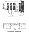
- a snubblerless 10KVA Matrix Converter uses discrete 65Amp, 1200 Volt MOS Controlled Thyristors (MCTs) as shown in Figure 1 .
- MCTs Volt MOS Controlled Thyristors
- the commutation time is minimised in order to achieve the optimum waveform quality; this is particularly useful when controlling induction motors in applications where the controller may demand very low output voltages.
- One application is in electric vehicle applications, primarily for motor control.
- electric vehicles especially military vehicles, weight and volume reduction are critical. Further, high-temperature operation is desirable to ease the problem of thermal management.
- the matrix converter of the present invention can have significant advantages over the traditional dc link converter in all of these areas, since it is possible to eliminate the dc link capacitor.
- most matrix converters have been concerned with insulated-gate bipolar transistor (IBGT) switches.
- the converter is controlled using a Venturini Control algorithm implemented on a simple micro controller.
- a FPGA controls the current commutation process.
- This hardware control platform allows the commutation time, T B , to be set by the user, with a minimum time of 100nsecs, which is very small compared to the switching time of the devices used (about 6usecs).
- Figure 2B shows the Matrix Converter operating with an output frequency of 40Hz into a 11kW induction motor load.
- the input filter is formed with the inductance of the paralleling inductors of the variac which supplies converter and the 15us capacitors attached to the input power planes.
- the three-step current commutation strategy operates well, there being no output voltage spikes and no input current spikes which would be seen during a commutation error of failure.
- the output voltage waveform is very clean, the laminated bus bar structure of the input voltage power planes producing a very small voltage overshoot during the voltage transients.
- the output has a DC bias much larger than the AC current.
- This DC current is due to the commutation strategy deciding a current direction for each output leg of the converter when the converter has zero current flowing, for example at turn-on.
- the improved output current waveforms obtained with a commutation time of 100 nsecs can be seen in the quality of the output current shown in Figure 2A .
- the critical commutation time, t B in Figure 7 for an MCT matrix converter is minimised towards, and to zero, and hence the output waveform quality can be substantially enhanced, particularly under conditions of low converter output voltage demand.
- the four-step matrix converter driver and control board contains all necessary components to provide firing signals for a three-phase to single-phase matrix converter.
- the four step semi-soft commutation method is implemented using a single Field Programmable Gate Array (FPGA) with a structure of allowing all of the necessary control logic to be integrated into one IC. With the critical commutation time, t B effectively reduced to zero, this becomes a three-step commutation method.
- FPGA Field Programmable Gate Array
- timers such as timers, PWM generators and state machines
- the timers are configurable and extremely versatile to allow use of a wide variety of semiconductor devices with different switching speeds.
- a docking port for a micro controller card is provided.
- Analogue receivers and conditioners are included for the necessary feedback signals. For convenience and noise immunity reasons, only one 5V supply is need for the board. All other necessary power supplies are generated locally.
- FIG. 3 shows the board with the following elements:
- the analogue area of the board allows voltage and current inputs to be transformed so that the micro controller can sample them.
- High Impedance 15V differential inputs are provided to reduce conducted noise.
- This stage has a gain of 1/3.
- the next stage is an offset and gain stage.
- the micro controller can only sample positive voltages so an offset is used to move the input waveforms.
- the offset voltage for all stages is controlled by the potentiometer and the op-amp at the bottom right of the analogue circuit area. The final gain and offset are then fine-tuned by the variable resistors.
- the upper resistor in each channel controls the gain and the lower controls the offset.
- the micro-controller has only one integrated sample-and-hold channel since large amounts of silicon area are used up by these. These multiple voltages cannot be sampled at the same instant in time. For this reason, a dedicated sample-and-hold chip (Analog Device SMP04E) is included on the board.
- a dedicated sample-and-hold chip Analog Device SMP04E
- the analogue-to-digital converter of the SAB 167 accepts inputs in the range of between 0-5V.
- the Varef pin of the processor needs to be connected to the 5V rail. It has been found that noise on the 5V rail caused by the SAB167 is transferred to the sampled analogue data. For this reason, a stable 4V reference has been placed on the board. This then reduces the input range of the micro controller to 0-4V.
- the previously described circuitry is used to ensure the input voltage range is not exceeded.
- the OP-Amps require supply voltages of +15V and the S/H integrated circuits uses +8V and -5V. All of these voltages are generated by the onboard DC-DC converter and the linear regulators from the 5V supply. This also makes the analogue circuitry more immune to digital noise.
- the current direction information is used by the FPGA Controller to determine the firing sequence during a current commutation.
- the FPGA Controller has two current direction inputs that can be used. The first is connected to a fibre optic receiver (HFBR2521). The second is connected to an opto-coupler (HCPL2611). Connection to the opto-coupler is through an SMB connector with the anode of the opto-coupler connected to the centre pin.
- the second current direction input is also wire-Ored to an auxiliary MOSFET and can be driven from the edge connector.
- the gate of the MOSFET is optimised for 5V signals. Only one of these signals is used for the commutation process. The signal that is used depends on the configuration DIP switches (see Section 5.1.1).
- the current direction signal can also be forced to a particular direction internally for testing purposes.
- the design of the FPGA controller ensures that there are no external filtering or latching requirements for the signal.
- a 9-way D-type connector is included on the board for pre-rack mounting testing. Only a standard serial port extension cable is required. The connections are such that no null modem wire swapping is required.
- the TQM 167LCD serial port lines are also connected to the edge connector for future use.
- the PC serial port lines RTS and DTR are used to reset and bootload the micro controller.
- these lines can be toggled by the terminal program used to communicate with the micro controller causing a reset to occur.
- two jumpers are used to break the connections of the RTS and DTR lines when not bootloading. Only the TxD and RxD lines are required to communicate with the micro controller during normal operations. If preferred, the connector on top of the TQM167LCD can be used. Care must then be taken with the RTS and DTR lines for the reasons outlined above.
- the output gate drive fibre optic components (HFBR 1521) are driven by a series connection of a MOSFET, resistor and the opto diode.
- the MOSFET is directly driven by the FPGA controller.
- the polarity of the outputs (active high or active low) can be changed to suit the application (see Section 5.1.5).
- the fibre optic transmitter at the top of the board of Figure 3 is used for the forward device in commutation cell number 1 (1F), the next is for the reverse device (1R) and so on. This can be seen more clearly in Figure 4 .
- All of the necessary connections to the micro controller card are provided using the two connectors on the board. These connections include the analogue signal lines together with the analogue reference, the serial port lines and connections to the FPGA controller. Three lines are used to connect the SAB167 and the FPGA. One line is used as an enable line. The other two are used for the PWM demand.
- Figure 5 shows a typical PWM output period from the micro controller. The decoding of these signals into the three six output signals is done internally in the FPGA controller. During period A, the outputs of commutation cell 1 are active, during B cell 2 is active and finally during C cell 3 is active.
- the push button enable and disable push buttons are not active. Only the enable line from the SAB 167 is used to enable and disable the FPGA outputs. A line is also used for to trigger the sample and hold IC.
- FIG. 4B and Table 1 above show the connections to the edge connector. All connections are made to the underside of the edge connector with the exception of the power supply connections which are attached to both the underside and the component side.
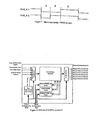
- FIG. 6 shows a high level schematic of the FPGA controller.
- the FPGA acts an interface between the PWM demands of the micro controller and the output requirements of the commutation process.
- the output stage is controlled in such a way as to implement the standard 4-step semi-soft commutation strategy to avoid line to line short circuits or load open circuits.
- the FPGA contains all the necessary circuitry to implement the three necessary timers and the current direction input conditioning.
- Various test modes are also included for converter operation without the need to the micro controller using an internal PWM generator. These modes are described in Section 5.1.2.
- the FPGA is configured with the use of DIP switches on the board. The polarity of the output stage and the current direction inputs can be changed according to the desired application thus removing constraints on providing external inverters for interfacing.
- the DIP switches produce a logic 0 is switched to the "on” position and floats to a logic “1” if in the "off' position.
- Table 2 shows the pin naming convention for the FPGA configuration DIP switches (labelled “Config" on the board).
- Table 2 Switch No. 1 2 3 4 5 6 7 8 9 10 Switch Name Circonf1 Circonf2 Test1 Test2 Test3 Testsp1 Testsp2 Globaldiv2 Activeout Activecin
- Test1 Test2 Test3 Operation 0 0 0 SAB167 Controlled 0 0 1 3 Phase Test mode 0 1 X 2 phase commutate between cells I and 2 1 0 X 2 phase commutate between cells 2 and 3 1 1 X 2 phase commutate between cells 3 and 1 NOTE: When the FPGA Controller is set to be controlled by the micro controller the push button enable and disable are not active. The outputs are enabled by the micro controller.
- Testsp1 Testsp2 Frequency 0 0 5 kHz 0 1 2.5 kHz 1 0 1.25 kHz 1 1 625 Hz
- the activein and activeout switches control the polarity of the outputs and the CIN inputs. If activeout is set to 1, a 1 will appear at the output of the FPGA (the fibre optic transmitter will be driven) when a device should be turned on. The reverse is true if the switch is set to 0.
- a positive current flows from utility to load
- a logic 1 This can be inverted inside the FPGA so that the designer need not worry about signal polarity when designing the current direction detection circuitry.
- activein is set to logic 1, it is assumed that a logic 1 on the input to the FPGA is positive current (i.e active high). If the activein is set to 0 then a 0 at the input to the FPGA will mean positive current flow (i.e current direction is then active low). Any inversion due to the on board current direction receiving components also need to be taken into consideration. Setting activecin to either value will not affect the direction value if the current direction is forced using one of the test modes.
- FIG 7 shows the output waveforms achieved by the switches shown in Figure 8 for the commutation from cell 1 to switch cell 2 assuming the current to be in the direction shown.
- the times marked T A , T B and T C are defined as the "reverse switch off time", the “commutation time” and the “reverse switch on time” respectively.
- Each of these delays has its own configurable timer.
- Each of the three DIP switches are identical and control one timer each.
- the "reverse switch off time” timer is marked “R-off' on the board, the "commutation time” timer is marked “Comm” and the "reverse switch on time” timer is marked “R-on”. Since each of the timer configuration settings are identical, only one will be described.
- Table 6 shows the switch usage for the commutation timer.
- Table 6 Switch No. Switch Name Switch No. Switch Name I CommDiv1 6 CommDIP5 2 CommDiv0 7 CommDIP4 3 Not Used 8 CommDIP3 4 CommDIP7 9 CommDIP2 5 CommDIP6 10 CommDIP1
- the switches labelled “CommDIP1-7” form the input to a 7-bit binary counter, CommDIP1 being the "least significant bit” and CommDIP7 being the "most significant bit”.
- the timer counts up to the value specified on the CommDIP switches before resetting to create the variable delay required.
- the switches labelled CommDIV0-1 are used to dictate the input clock speed into the timer. Table 7 below shows all available clock periods assuming 10MHz clock is used to clock the FPGA controller.
- the timer time is calculated by multiplying the selected clock period by the binary number set on the CommDIP switches (remembering that a logic 0 is produced when the switch is on and a 1 when off when setting the DIP switches) and then adding one FPGA clock period (100ns for the 10MHZ clock). For example, if the timer was to be set to its maximum value (Globaldiv2 is also set to 0 to double the delay), all seven bits set to high on the CommDIP switches will cause a maximum count of 127, this multiplied by a period of 1.6 ⁇ gives 203.2 ⁇ s plus 100ns gives a maximum delay of 203.3 ⁇ s.
- the timer delay is set to 100ns. This wide range of timer values makes the FPGA controller suitable for most types of semiconductor switching devices.
- the "reverse off' and “reverse on” timers are configured in the same way. 'reverse off timer' Switch No. Switch Name Switch No. Switch Name 1 R-offDIV1 6 R-offDIP5 2 R-offDIV0 7 R-offDIP4 3 Not Used 8 R-offDIP3 4 R-offDIP7 9 R-offDIP2 5 R-offDIP6 10 R-offDIP1 Table 8 Switch No. Switch Name Switch No.
- Table 11 gives some examples of possible timer DIP switch settings and their resultant delay times.
- Table 11 Globaldiv2 DIV1 DIV0 DIP DELAY 7 6 5 4 3 2 1 1 0 0 0 0 0 0 0 0 0 0 0 100ns 1 0 0 0 0 0 0 1 0 0 500ns 1 0 0 0 0 0 1 0 0 1 1 ⁇ s 1 0 1 0 0 0 0 1 0 900ns 1 0 1 0 0 0 0 1 0 1 0 2.1 ⁇ s 1 1 0 0 1 1 0 0 1 0 20.1 ⁇ s 1 1 0 1 1 1 1 1 1 1 50.9 ⁇ s 1 1 1 0 0 0 1 0 0 0 0 6.5 ⁇ s 1 1 1 1 0 0 0 0 0 0 51.3 0 0 0 0 0 0 0 1 0 0 900ns 0 0
- the switch names used are general since they can be applied to any of the three timers.
Landscapes
- Engineering & Computer Science (AREA)
- Power Engineering (AREA)
- Inverter Devices (AREA)
- Amplifiers (AREA)
- Control Of Eletrric Generators (AREA)
- Electric Propulsion And Braking For Vehicles (AREA)
- Control Of Multiple Motors (AREA)
- Control Of Ac Motors In General (AREA)
Claims (16)
- Matrixwandler mit einer Strom-Kommutations-Schaltung mit einer Mehrzahl von bi-direktionalen Leistungshalbleiterschaltern (E), die in einer Matrixkonfiguration angeordnet sind, dadurch gekennzeichnet, dass die Matrixschalteranordnung Zeitsteuerungs/Verzögerungs-Betriebe zur Durchführung von Kommutationsfunktionen mit der Initiation eines Schalters vor der Deaktivierung eines anderen Schalters durchführt, wobei die Matrixschalteranordnung ein Kommutationsintervall bereitstellt, das gleich oder annähernd gleich Null ist.
- Wandler nach Anspruch 1, bei dem die Matrixschalteranordnung (E) Zeitsteuerungs/Verzögerungs-Betriebe der bi-direktionalen Leistungshalbleiterschalter entsprechend einer oder mehrerer der Tabellen 6 bis 11 umfasst.
- Wandler nach Anspruch 1 oder 2, bei dem die Matrixschalteranordnung (E) einen ersten Schalter und einen zweiten Schalter umfasst, wobei in einem ersten Betriebsmodus der erste Schalter aktiviert und der zweite Schalter nicht aktiviert ist, und wobei die Matrixschalteranordnung Zeitsteuerungs/Verzögerungs-Betriebe mit der Aktivierung des zweiten Schalters vor der Deaktivierung des ersten Schalters durchführt.
- Wandler nach einem der vorangehenden Ansprüche, bei dem die Matrixschalteranordnung (E) eine Schaltung umfasst, die Zeitsteuerungs/Verzögerungs-Betriebe der Schalter durchführt, um das Kommutationsintervall zu minimieren.
- Wandler nach einem der vorangehenden Ansprüche, bei dem die Matrixschalteranordnung (E) eine Schaltung umfasst, die Zeitsteuerungs/Verzögerungs-Betriebe der Schalter durchführt, um ein Kommutationsintervall bereitzustellen, das kleiner als die üblicherweise, als Tatzeit in einem Spannungsquelleninverter verwendete ist.
- Wandler nach einem der vorangehenden Ansprüche, bei dem die Matrixschalteranordnung (E) eine Schaltung umfasst, die Zeitsteuerungs/Verzögerungs-Betriebe der Schalter durchführt, um ein Kommutationsintervall bereitzustellen, das Negativ ist.
- Verfahren zum Betreiben eines Matrixkonverters mit einer Mehrzahl von bi-direktionalen Leistungshalbleiterschaltern (E), die in einer Matrixkonfiguration angeordnet sind, wobei das Verfahren umfasst: Betreiben der Matrixschalteranordnung zur Durchführung von Zeitsteuerungs/Verzögerungs-Betrieben zur Ausführung von Kommutationsfunktionen mit einer Aktivierung eines Schalters vor der Deaktivierung eines anderen Schalters, wobei ein Kommutationsintervall gleich oder nahe bei Null ist.
- Verfahren nach Anspruch 7 mit der Matrixschalteranordnung (E) zur Durchführung der Zeitsteuerungs/Verzögerungs-Betriebe der bi-direktionalen Leitungshalbleiterschalter entsprechend einer oder mehrere der Tabellen 6 bis 11.
- Verfahren nach Anspruch 7 oder 8, bei dem in einem ersten Betriebsmodus der erste Schalter aktiviert und der zweite Schalter nicht aktiviert ist, und dann die Matrixschalteranordnung den zweiten Schalter aktiviert, bevor der erste Schalter deaktiviert wird.
- Verfahren nach einem der Ansprüche 7 bis 9, bei dem die Matrixschalteranordnung (E) Zeitsteuerungs/Verzögerungs-Betriebe der Schalter durchführt, um so dass Kommutationsintervall zu minimieren.
- Verfahren nach einem der Ansprüche 7 bis 10, bei dem die Matrixschalteranordnung (E) Zeitsteuerungs/Verzögerungs-Betriebe des Schalters durchführt, wodurch ein Kommutationsintervall bereit gestellt wird, das kleiner als die üblicherweise als Tatzeit in einem Spannungsquelleninverter verwendet ist.
- Verfahren nach einem der Ansprüche 7 bis 11, bei dem die Matrixschalteranordnung (E) Zeitsteuerungs/Verzögerungs-Betriebe des Schalters durchführt, wodurch ein Kommutationsintervall bereitgestellt wird, das Negativ ist.
- Verfahren nach einem der Ansprüche 7 bis 12, bei dem die Matrixschalteranordnung (E) Zeitsteuerungs/Verzögerungs-Betriebe an dem Schalter durchführt, wodurch eine Verringerung des Kommutationsintervalls erzielt wird.
- Computerprogrammprodukt, das direkt in den internen Speicher eines digitalen Computers ladbar ist, mit Softwarecodeabschnitten zur Durchführung des Verfahrens nach Anspruch 7 bis 13, wenn das Produkt auf einem Computer läuft.
- Computerprogramm, das direkt in den internen Speicher eines digitalen Computers ladbar ist, mit Softwarecodeabschnitten zur Durchführung des Verfahrens nach Anspruch 7 bis 13, wenn das Programm auf einem Computer läuft.
- Computerprogramm nach Anspruch 14 auf einem Träger, der elektronische Signale umfassen kann.
Applications Claiming Priority (3)
| Application Number | Priority Date | Filing Date | Title |
|---|---|---|---|
| GBGB0208600.7A GB0208600D0 (en) | 2002-04-15 | 2002-04-15 | Power converter |
| GB0208600 | 2002-04-15 | ||
| PCT/GB2003/001633 WO2003090337A1 (en) | 2002-04-15 | 2003-04-15 | Power converter |
Publications (2)
| Publication Number | Publication Date |
|---|---|
| EP1495533A1 EP1495533A1 (de) | 2005-01-12 |
| EP1495533B1 true EP1495533B1 (de) | 2009-03-11 |
Family
ID=9934848
Family Applications (1)
| Application Number | Title | Priority Date | Filing Date |
|---|---|---|---|
| EP03746857A Expired - Lifetime EP1495533B1 (de) | 2002-04-15 | 2003-04-15 | Stromumsetzer |
Country Status (7)
| Country | Link |
|---|---|
| US (1) | US20050281066A1 (de) |
| EP (1) | EP1495533B1 (de) |
| AT (1) | ATE425573T1 (de) |
| AU (1) | AU2003226544A1 (de) |
| DE (1) | DE60326556D1 (de) |
| GB (1) | GB0208600D0 (de) |
| WO (1) | WO2003090337A1 (de) |
Cited By (3)
| Publication number | Priority date | Publication date | Assignee | Title |
|---|---|---|---|---|
| RU2525863C1 (ru) * | 2010-07-13 | 2014-08-20 | Ниссан Мотор Ко., Лтд. | Система преобразования мощности |
| US10855146B2 (en) | 2016-03-11 | 2020-12-01 | Itt Manufacturing Enterprises Llc | Motor drive unit |
| US11848619B2 (en) | 2020-01-21 | 2023-12-19 | Itt Manufacturing Enterprises Llc | Apparatus and methods for supplying DC power to control circuitry of a matrix converter |
Families Citing this family (10)
| Publication number | Priority date | Publication date | Assignee | Title |
|---|---|---|---|---|
| US8030788B2 (en) * | 2008-12-31 | 2011-10-04 | General Electric Company | Method and systems for an engine starter/generator |
| US9478378B2 (en) * | 2013-01-04 | 2016-10-25 | Schweitzer Engineering Laboratories, Inc. | Preventing out-of-synchronism reclosing between power systems |
| TWI468710B (zh) * | 2013-03-25 | 2015-01-11 | Test Research Inc | 用於電壓設定的測試機台 |
| TWI548186B (zh) * | 2014-08-15 | 2016-09-01 | Richtek Technology Corp | Quick Start Circuit and Method of Chi - back Power Supply |
| GB2538312B (en) * | 2015-05-15 | 2021-07-14 | Itt Mfg Enterprises Llc | Bidirectional energy transfer control |
| US9735771B1 (en) * | 2016-07-21 | 2017-08-15 | Hella Kgaa Hueck & Co. | Hybrid switch including GaN HEMT and MOSFET |
| GB2557294B (en) | 2016-12-05 | 2022-03-30 | Itt Mfg Enterprises Llc | Matrix converter control method and system |
| DE102018006120A1 (de) * | 2018-08-02 | 2020-02-06 | Mbda Deutschland Gmbh | Selbstgeführter Direktumrichter und Ansteuerverfahren für selbstgeführten Direktumrichter |
| US11394264B2 (en) | 2020-01-21 | 2022-07-19 | Itt Manufacturing Enterprises Llc | Motor assembly for driving a pump or rotary device with a low inductance resistor for a matrix converter |
| US11448225B2 (en) | 2020-01-21 | 2022-09-20 | Itt Manufacturing Enterprises Llc | Motor assembly for driving a pump or rotary device having a cooling duct |
Family Cites Families (19)
| Publication number | Priority date | Publication date | Assignee | Title |
|---|---|---|---|---|
| US3470447A (en) * | 1967-04-21 | 1969-09-30 | Westinghouse Electric Corp | Static frequency converter with novel voltage control |
| US4648022A (en) * | 1986-02-14 | 1987-03-03 | Westinghouse Electric Corp. | Matrix converter control system |
| US4642751A (en) * | 1986-02-14 | 1987-02-10 | Westinghouse Electric Corp. | Hidden DC-link AC/AC converter using bilateral power switches |
| US4713743A (en) * | 1987-02-06 | 1987-12-15 | Westinghouse Electric Corp. | Load-commutated inverter and synchronous motor drive embodying the same |
| US4833588A (en) * | 1988-08-31 | 1989-05-23 | Westinghouse Electric Corp. | Direct AC/AC converter system |
| US5005115A (en) * | 1989-07-28 | 1991-04-02 | Westinghouse Electric Corp. | Forced-commutated current-source converter and AC motor drive using the same |
| US5214366A (en) * | 1989-11-13 | 1993-05-25 | Siemens Aktiengesellschaft | Three-phase converter for polyphase induction motors |
| JPH07213062A (ja) * | 1994-01-24 | 1995-08-11 | Nippon Electric Ind Co Ltd | Pwmサイクロコンバータのゲート信号生成方法 |
| US5594636A (en) * | 1994-06-29 | 1997-01-14 | Northrop Grumman Corporation | Matrix converter circuit and commutating method |
| JPH08289564A (ja) * | 1995-04-14 | 1996-11-01 | Nippon Electric Ind Co Ltd | 高周波リンクdc/acコンバータの転流重なり期間の補正法 |
| US5852559A (en) * | 1996-09-24 | 1998-12-22 | Allen Bradley Company, Llc | Power application circuits utilizing bidirectional insulated gate bipolar transistor |
| US5977569A (en) * | 1996-09-24 | 1999-11-02 | Allen-Bradley Company, Llc | Bidirectional lateral insulated gate bipolar transistor having increased voltage blocking capability |
| DE19639773A1 (de) * | 1996-09-27 | 1998-04-02 | Abb Patent Gmbh | Dreiphasiger Matrix-Stromrichter und Verfahren zum Betrieb |
| US5909367A (en) * | 1997-06-02 | 1999-06-01 | Reliance Electric Industrial Company | Modular AC-AC variable voltage and variable frequency power conveter system and control |
| US5892677A (en) * | 1997-06-02 | 1999-04-06 | Reliance Electric Industrial Company | Adaptive overlapping communication control of modular AC-AC converter and integration with device module of multiple AC-AC switches |
| DE19746797B4 (de) * | 1997-10-23 | 2012-05-24 | Siemens Ag | Verfahren zur Steuerung bidirektionaler Schalter in Stromrichtern |
| US6166930A (en) * | 1999-05-12 | 2000-12-26 | Otis Elevator Company | Reduced common voltage in a DC matrix converter |
| US6058028A (en) * | 1999-05-12 | 2000-05-02 | Otis Elevator Company | Control of a DC matrix converter |
| US6137703A (en) * | 1999-11-23 | 2000-10-24 | Otis Elevator Company | Clamped bidirectional power switches |
-
2002
- 2002-04-15 GB GBGB0208600.7A patent/GB0208600D0/en not_active Ceased
-
2003
- 2003-04-15 AT AT03746857T patent/ATE425573T1/de not_active IP Right Cessation
- 2003-04-15 AU AU2003226544A patent/AU2003226544A1/en not_active Abandoned
- 2003-04-15 US US10/511,234 patent/US20050281066A1/en not_active Abandoned
- 2003-04-15 DE DE60326556T patent/DE60326556D1/de not_active Expired - Fee Related
- 2003-04-15 WO PCT/GB2003/001633 patent/WO2003090337A1/en not_active Ceased
- 2003-04-15 EP EP03746857A patent/EP1495533B1/de not_active Expired - Lifetime
Cited By (4)
| Publication number | Priority date | Publication date | Assignee | Title |
|---|---|---|---|---|
| RU2525863C1 (ru) * | 2010-07-13 | 2014-08-20 | Ниссан Мотор Ко., Лтд. | Система преобразования мощности |
| US10855146B2 (en) | 2016-03-11 | 2020-12-01 | Itt Manufacturing Enterprises Llc | Motor drive unit |
| US11855495B2 (en) | 2016-03-11 | 2023-12-26 | Itt Manufacturing Enterprises Llc | Motor drive unit |
| US11848619B2 (en) | 2020-01-21 | 2023-12-19 | Itt Manufacturing Enterprises Llc | Apparatus and methods for supplying DC power to control circuitry of a matrix converter |
Also Published As
| Publication number | Publication date |
|---|---|
| EP1495533A1 (de) | 2005-01-12 |
| DE60326556D1 (de) | 2009-04-23 |
| GB0208600D0 (en) | 2002-05-22 |
| ATE425573T1 (de) | 2009-03-15 |
| AU2003226544A1 (en) | 2003-11-03 |
| US20050281066A1 (en) | 2005-12-22 |
| WO2003090337A1 (en) | 2003-10-30 |
Similar Documents
| Publication | Publication Date | Title |
|---|---|---|
| EP1495533B1 (de) | Stromumsetzer | |
| EP2140544B1 (de) | Signalumsetzer zur erzeugung von ansteuersignalen für einen mehrstufigen stromrichter, pwm-ansteuerschaltung | |
| US6069809A (en) | Resonant inverter apparatus | |
| US9479083B2 (en) | Power converter in which switching elements are driven in parallel | |
| US9912279B2 (en) | Circuit with current sharing alternately switched parallel transistors | |
| WO2002095914A2 (en) | Half-bridge gate driver circuit | |
| EP2128971B1 (de) | Systeme und Verfahren zur Steuerung eines Wandlers zum Antrieb einer Last | |
| Miryala et al. | Active gate driving technique for series connecting SiC MOSFETs in the presence of gate pulse delay mismatch | |
| US6452365B1 (en) | Power converter with increased breakdown voltage maintaining stable operation | |
| JP2004266884A (ja) | スイッチング電源式電源装置およびそれを用いた核磁気共鳴イメージング装置 | |
| EP2722986A2 (de) | Schaltung zur Synchronumschaltung von in Serie geschalteten elektronischen Schaltern | |
| US20230412431A1 (en) | Multi-channel digital isolator with integrated configurable pulse width modulation interlock protection | |
| US7480160B2 (en) | Traction converter having a line-side four-quadrant controller, and method therefor | |
| CN114884493B (zh) | 一种pwm信号解码器及使用其的单输入高压集成电路 | |
| EP4432562A1 (de) | Treiberschaltung mit entladungssteuerung, entsprechendes elektronisches system und fahrzeug | |
| EP2712087B1 (de) | Halbleitervorrichtung und schaltung zur steuerung des elektrischen potenzials eines isolierten gates eines schaltelements | |
| Takayama et al. | Binary-weighted modular multi-level digital active gate driver | |
| Schmitt et al. | Voltage gradient limitation of IGBTS by optimised gate-current profiles | |
| EP4482005A1 (de) | Anordnung zur stromteilung von parallel geschalteten wandlern | |
| US20250392304A1 (en) | Gate driver and switching apparatus | |
| Klumpner et al. | A cost-effective solution to power the gate drivers of multilevel inverters using the bootstrap power supply technique | |
| JP6984727B2 (ja) | 電力変換装置および電動機システム | |
| Horii et al. | Large current output digital gate driver using half-bridge digital-to-analog converter IC and two power MOSFETs | |
| JP7083265B2 (ja) | パワートランジスタの駆動回路、パワーモジュール | |
| CN119229767B (zh) | 栅极驱动电路、栅极驱动芯片、智能功率模块和设备 |
Legal Events
| Date | Code | Title | Description |
|---|---|---|---|
| PUAI | Public reference made under article 153(3) epc to a published international application that has entered the european phase |
Free format text: ORIGINAL CODE: 0009012 |
|
| 17P | Request for examination filed |
Effective date: 20041015 |
|
| AK | Designated contracting states |
Kind code of ref document: A1 Designated state(s): AT BE BG CH CY CZ DE DK EE ES FI FR GB GR HU IE IT LI LU MC NL PT RO SE SI SK TR |
|
| AX | Request for extension of the european patent |
Extension state: AL LT LV MK |
|
| RIN1 | Information on inventor provided before grant (corrected) |
Inventor name: CLARE, JONATHON Inventor name: WHEELER, PATRICK Inventor name: EMPRINGHAM, LEE |
|
| RIN1 | Information on inventor provided before grant (corrected) |
Inventor name: WHEELER, PATRICK Inventor name: CLARE, JONATHAN Inventor name: EMPRINGHAM, LEE |
|
| 17Q | First examination report despatched |
Effective date: 20061221 |
|
| GRAP | Despatch of communication of intention to grant a patent |
Free format text: ORIGINAL CODE: EPIDOSNIGR1 |
|
| GRAS | Grant fee paid |
Free format text: ORIGINAL CODE: EPIDOSNIGR3 |
|
| GRAA | (expected) grant |
Free format text: ORIGINAL CODE: 0009210 |
|
| AK | Designated contracting states |
Kind code of ref document: B1 Designated state(s): AT BE BG CH CY CZ DE DK EE ES FI FR GB GR HU IE IT LI LU MC NL PT RO SE SI SK TR |
|
| REG | Reference to a national code |
Ref country code: GB Ref legal event code: FG4D |
|
| REG | Reference to a national code |
Ref country code: CH Ref legal event code: EP |
|
| REG | Reference to a national code |
Ref country code: IE Ref legal event code: FG4D |
|
| REF | Corresponds to: |
Ref document number: 60326556 Country of ref document: DE Date of ref document: 20090423 Kind code of ref document: P |
|
| PG25 | Lapsed in a contracting state [announced via postgrant information from national office to epo] |
Ref country code: FI Free format text: LAPSE BECAUSE OF FAILURE TO SUBMIT A TRANSLATION OF THE DESCRIPTION OR TO PAY THE FEE WITHIN THE PRESCRIBED TIME-LIMIT Effective date: 20090311 Ref country code: SI Free format text: LAPSE BECAUSE OF FAILURE TO SUBMIT A TRANSLATION OF THE DESCRIPTION OR TO PAY THE FEE WITHIN THE PRESCRIBED TIME-LIMIT Effective date: 20090311 Ref country code: NL Free format text: LAPSE BECAUSE OF FAILURE TO SUBMIT A TRANSLATION OF THE DESCRIPTION OR TO PAY THE FEE WITHIN THE PRESCRIBED TIME-LIMIT Effective date: 20090311 |
|
| PGFP | Annual fee paid to national office [announced via postgrant information from national office to epo] |
Ref country code: DK Payment date: 20090430 Year of fee payment: 7 Ref country code: ES Payment date: 20090519 Year of fee payment: 7 Ref country code: IE Payment date: 20090501 Year of fee payment: 7 Ref country code: MC Payment date: 20090430 Year of fee payment: 7 |
|
| NLV1 | Nl: lapsed or annulled due to failure to fulfill the requirements of art. 29p and 29m of the patents act | ||
| PG25 | Lapsed in a contracting state [announced via postgrant information from national office to epo] |
Ref country code: AT Free format text: LAPSE BECAUSE OF FAILURE TO SUBMIT A TRANSLATION OF THE DESCRIPTION OR TO PAY THE FEE WITHIN THE PRESCRIBED TIME-LIMIT Effective date: 20090311 Ref country code: SE Free format text: LAPSE BECAUSE OF FAILURE TO SUBMIT A TRANSLATION OF THE DESCRIPTION OR TO PAY THE FEE WITHIN THE PRESCRIBED TIME-LIMIT Effective date: 20090611 |
|
| PGFP | Annual fee paid to national office [announced via postgrant information from national office to epo] |
Ref country code: DE Payment date: 20090420 Year of fee payment: 7 Ref country code: FR Payment date: 20090429 Year of fee payment: 7 Ref country code: LU Payment date: 20090522 Year of fee payment: 7 Ref country code: NL Payment date: 20090426 Year of fee payment: 7 |
|
| PG25 | Lapsed in a contracting state [announced via postgrant information from national office to epo] |
Ref country code: BE Free format text: LAPSE BECAUSE OF FAILURE TO SUBMIT A TRANSLATION OF THE DESCRIPTION OR TO PAY THE FEE WITHIN THE PRESCRIBED TIME-LIMIT Effective date: 20090311 |
|
| PGFP | Annual fee paid to national office [announced via postgrant information from national office to epo] |
Ref country code: BE Payment date: 20090428 Year of fee payment: 7 |
|
| PG25 | Lapsed in a contracting state [announced via postgrant information from national office to epo] |
Ref country code: CZ Free format text: LAPSE BECAUSE OF FAILURE TO SUBMIT A TRANSLATION OF THE DESCRIPTION OR TO PAY THE FEE WITHIN THE PRESCRIBED TIME-LIMIT Effective date: 20090311 Ref country code: ES Free format text: LAPSE BECAUSE OF FAILURE TO SUBMIT A TRANSLATION OF THE DESCRIPTION OR TO PAY THE FEE WITHIN THE PRESCRIBED TIME-LIMIT Effective date: 20090622 Ref country code: EE Free format text: LAPSE BECAUSE OF FAILURE TO SUBMIT A TRANSLATION OF THE DESCRIPTION OR TO PAY THE FEE WITHIN THE PRESCRIBED TIME-LIMIT Effective date: 20090311 Ref country code: PT Free format text: LAPSE BECAUSE OF FAILURE TO SUBMIT A TRANSLATION OF THE DESCRIPTION OR TO PAY THE FEE WITHIN THE PRESCRIBED TIME-LIMIT Effective date: 20090824 |
|
| PGFP | Annual fee paid to national office [announced via postgrant information from national office to epo] |
Ref country code: CH Payment date: 20090416 Year of fee payment: 7 |
|
| PG25 | Lapsed in a contracting state [announced via postgrant information from national office to epo] |
Ref country code: SK Free format text: LAPSE BECAUSE OF FAILURE TO SUBMIT A TRANSLATION OF THE DESCRIPTION OR TO PAY THE FEE WITHIN THE PRESCRIBED TIME-LIMIT Effective date: 20090311 Ref country code: RO Free format text: LAPSE BECAUSE OF FAILURE TO SUBMIT A TRANSLATION OF THE DESCRIPTION OR TO PAY THE FEE WITHIN THE PRESCRIBED TIME-LIMIT Effective date: 20090311 |
|
| PGFP | Annual fee paid to national office [announced via postgrant information from national office to epo] |
Ref country code: GB Payment date: 20090415 Year of fee payment: 7 |
|
| PG25 | Lapsed in a contracting state [announced via postgrant information from national office to epo] |
Ref country code: DK Free format text: LAPSE BECAUSE OF NON-PAYMENT OF DUE FEES Effective date: 20090311 |
|
| PLBE | No opposition filed within time limit |
Free format text: ORIGINAL CODE: 0009261 |
|
| STAA | Information on the status of an ep patent application or granted ep patent |
Free format text: STATUS: NO OPPOSITION FILED WITHIN TIME LIMIT |
|
| PG25 | Lapsed in a contracting state [announced via postgrant information from national office to epo] |
Ref country code: BG Free format text: LAPSE BECAUSE OF FAILURE TO SUBMIT A TRANSLATION OF THE DESCRIPTION OR TO PAY THE FEE WITHIN THE PRESCRIBED TIME-LIMIT Effective date: 20090611 |
|
| 26N | No opposition filed |
Effective date: 20091214 |
|
| PG25 | Lapsed in a contracting state [announced via postgrant information from national office to epo] |
Ref country code: GR Free format text: LAPSE BECAUSE OF FAILURE TO SUBMIT A TRANSLATION OF THE DESCRIPTION OR TO PAY THE FEE WITHIN THE PRESCRIBED TIME-LIMIT Effective date: 20090612 |
|
| PG25 | Lapsed in a contracting state [announced via postgrant information from national office to epo] |
Ref country code: MC Free format text: LAPSE BECAUSE OF NON-PAYMENT OF DUE FEES Effective date: 20100430 |
|
| REG | Reference to a national code |
Ref country code: CH Ref legal event code: PL |
|
| GBPC | Gb: european patent ceased through non-payment of renewal fee |
Effective date: 20100415 |
|
| REG | Reference to a national code |
Ref country code: IE Ref legal event code: MM4A |
|
| REG | Reference to a national code |
Ref country code: FR Ref legal event code: ST Effective date: 20101230 |
|
| PG25 | Lapsed in a contracting state [announced via postgrant information from national office to epo] |
Ref country code: IE Free format text: LAPSE BECAUSE OF NON-PAYMENT OF DUE FEES Effective date: 20100415 |
|
| PG25 | Lapsed in a contracting state [announced via postgrant information from national office to epo] |
Ref country code: LI Free format text: LAPSE BECAUSE OF NON-PAYMENT OF DUE FEES Effective date: 20100430 Ref country code: DE Free format text: LAPSE BECAUSE OF NON-PAYMENT OF DUE FEES Effective date: 20101103 Ref country code: CH Free format text: LAPSE BECAUSE OF NON-PAYMENT OF DUE FEES Effective date: 20100430 |
|
| PG25 | Lapsed in a contracting state [announced via postgrant information from national office to epo] |
Ref country code: GB Free format text: LAPSE BECAUSE OF NON-PAYMENT OF DUE FEES Effective date: 20100415 Ref country code: IT Free format text: LAPSE BECAUSE OF FAILURE TO SUBMIT A TRANSLATION OF THE DESCRIPTION OR TO PAY THE FEE WITHIN THE PRESCRIBED TIME-LIMIT Effective date: 20090311 |
|
| PG25 | Lapsed in a contracting state [announced via postgrant information from national office to epo] |
Ref country code: HU Free format text: LAPSE BECAUSE OF FAILURE TO SUBMIT A TRANSLATION OF THE DESCRIPTION OR TO PAY THE FEE WITHIN THE PRESCRIBED TIME-LIMIT Effective date: 20090912 |
|
| PG25 | Lapsed in a contracting state [announced via postgrant information from national office to epo] |
Ref country code: TR Free format text: LAPSE BECAUSE OF FAILURE TO SUBMIT A TRANSLATION OF THE DESCRIPTION OR TO PAY THE FEE WITHIN THE PRESCRIBED TIME-LIMIT Effective date: 20090311 |
|
| PG25 | Lapsed in a contracting state [announced via postgrant information from national office to epo] |
Ref country code: CY Free format text: LAPSE BECAUSE OF FAILURE TO SUBMIT A TRANSLATION OF THE DESCRIPTION OR TO PAY THE FEE WITHIN THE PRESCRIBED TIME-LIMIT Effective date: 20090311 |
|
| PG25 | Lapsed in a contracting state [announced via postgrant information from national office to epo] |
Ref country code: FR Free format text: LAPSE BECAUSE OF NON-PAYMENT OF DUE FEES Effective date: 20100430 |
|
| PG25 | Lapsed in a contracting state [announced via postgrant information from national office to epo] |
Ref country code: LU Free format text: LAPSE BECAUSE OF NON-PAYMENT OF DUE FEES Effective date: 20100415 |
|
| P01 | Opt-out of the competence of the unified patent court (upc) registered |
Effective date: 20230530 |