EP1495238B1 - Multifunction vibration isolation strut - Google Patents
Multifunction vibration isolation strut Download PDFInfo
- Publication number
- EP1495238B1 EP1495238B1 EP03721683A EP03721683A EP1495238B1 EP 1495238 B1 EP1495238 B1 EP 1495238B1 EP 03721683 A EP03721683 A EP 03721683A EP 03721683 A EP03721683 A EP 03721683A EP 1495238 B1 EP1495238 B1 EP 1495238B1
- Authority
- EP
- European Patent Office
- Prior art keywords
- load
- isolation
- hydraulic
- isolation strut
- piston
- Prior art date
- Legal status (The legal status is an assumption and is not a legal conclusion. Google has not performed a legal analysis and makes no representation as to the accuracy of the status listed.)
- Expired - Lifetime
Links
- 238000002955 isolation Methods 0.000 title claims description 58
- 239000000725 suspension Substances 0.000 claims description 18
- 238000013016 damping Methods 0.000 claims description 12
- 239000012530 fluid Substances 0.000 claims description 10
- 230000002159 abnormal effect Effects 0.000 claims description 2
- 230000000694 effects Effects 0.000 description 3
- 230000001419 dependent effect Effects 0.000 description 2
- 230000009977 dual effect Effects 0.000 description 2
- 230000010355 oscillation Effects 0.000 description 2
- 230000003466 anti-cipated effect Effects 0.000 description 1
- 230000000994 depressogenic effect Effects 0.000 description 1
- 238000010586 diagram Methods 0.000 description 1
- 238000009434 installation Methods 0.000 description 1
- 230000035939 shock Effects 0.000 description 1
- 230000003068 static effect Effects 0.000 description 1
- 230000001960 triggered effect Effects 0.000 description 1
Images



Classifications
-
- B—PERFORMING OPERATIONS; TRANSPORTING
- B60—VEHICLES IN GENERAL
- B60G—VEHICLE SUSPENSION ARRANGEMENTS
- B60G17/00—Resilient suspensions having means for adjusting the spring or vibration-damper characteristics, for regulating the distance between a supporting surface and a sprung part of vehicle or for locking suspension during use to meet varying vehicular or surface conditions, e.g. due to speed or load
- B60G17/005—Suspension locking arrangements
-
- F—MECHANICAL ENGINEERING; LIGHTING; HEATING; WEAPONS; BLASTING
- F16—ENGINEERING ELEMENTS AND UNITS; GENERAL MEASURES FOR PRODUCING AND MAINTAINING EFFECTIVE FUNCTIONING OF MACHINES OR INSTALLATIONS; THERMAL INSULATION IN GENERAL
- F16F—SPRINGS; SHOCK-ABSORBERS; MEANS FOR DAMPING VIBRATION
- F16F15/00—Suppression of vibrations in systems; Means or arrangements for avoiding or reducing out-of-balance forces, e.g. due to motion
- F16F15/02—Suppression of vibrations of non-rotating, e.g. reciprocating systems; Suppression of vibrations of rotating systems by use of members not moving with the rotating systems
- F16F15/023—Suppression of vibrations of non-rotating, e.g. reciprocating systems; Suppression of vibrations of rotating systems by use of members not moving with the rotating systems using fluid means
- F16F15/027—Suppression of vibrations of non-rotating, e.g. reciprocating systems; Suppression of vibrations of rotating systems by use of members not moving with the rotating systems using fluid means comprising control arrangements
- F16F15/0275—Control of stiffness
-
- F—MECHANICAL ENGINEERING; LIGHTING; HEATING; WEAPONS; BLASTING
- F16—ENGINEERING ELEMENTS AND UNITS; GENERAL MEASURES FOR PRODUCING AND MAINTAINING EFFECTIVE FUNCTIONING OF MACHINES OR INSTALLATIONS; THERMAL INSULATION IN GENERAL
- F16F—SPRINGS; SHOCK-ABSORBERS; MEANS FOR DAMPING VIBRATION
- F16F9/00—Springs, vibration-dampers, shock-absorbers, or similarly-constructed movement-dampers using a fluid or the equivalent as damping medium
- F16F9/06—Springs, vibration-dampers, shock-absorbers, or similarly-constructed movement-dampers using a fluid or the equivalent as damping medium using both gas and liquid
-
- F—MECHANICAL ENGINEERING; LIGHTING; HEATING; WEAPONS; BLASTING
- F16—ENGINEERING ELEMENTS AND UNITS; GENERAL MEASURES FOR PRODUCING AND MAINTAINING EFFECTIVE FUNCTIONING OF MACHINES OR INSTALLATIONS; THERMAL INSULATION IN GENERAL
- F16F—SPRINGS; SHOCK-ABSORBERS; MEANS FOR DAMPING VIBRATION
- F16F9/00—Springs, vibration-dampers, shock-absorbers, or similarly-constructed movement-dampers using a fluid or the equivalent as damping medium
- F16F9/10—Springs, vibration-dampers, shock-absorbers, or similarly-constructed movement-dampers using a fluid or the equivalent as damping medium using liquid only; using a fluid of which the nature is immaterial
- F16F9/14—Devices with one or more members, e.g. pistons, vanes, moving to and fro in chambers and using throttling effect
- F16F9/16—Devices with one or more members, e.g. pistons, vanes, moving to and fro in chambers and using throttling effect involving only straight-line movement of the effective parts
- F16F9/22—Devices with one or more members, e.g. pistons, vanes, moving to and fro in chambers and using throttling effect involving only straight-line movement of the effective parts with one or more cylinders each having a single working space closed by a piston or plunger
- F16F9/26—Devices with one or more members, e.g. pistons, vanes, moving to and fro in chambers and using throttling effect involving only straight-line movement of the effective parts with one or more cylinders each having a single working space closed by a piston or plunger with two cylinders in line and with the two pistons or plungers connected together
Definitions
- the present invention relates to a vibration isolation strut, and more particularly to a vibration isolation strut which is rigidly mounted for normal operation but which provides isolation from vibration, particularly seismic vibration.
- a support in such a manner that the support is relatively rigid during normal operation.
- An example is equipment such as an antenna system for a radar installation, but other examples include buildings, structures, or other equipment.
- a platform supporting the antenna is expected to provide a relatively rigid load path to the ground.
- Such a support is desirably relatively rigid in order to stabilize the structure for optimum performance and accuracy. Rigid supports, however, can cause damage to the supported structure in the event of violent shaking or vibration such as may be experienced during a seismic event.
- vibration or motion isolations have generally acted merely to isolate the load or a platform supporting the load from anticipated vibration.
- Examples of such isolations are found, for example, in the inventions of U.S. Patent 5,803,213, U.S. Patent 5,918,865, and U.S. Patent 5,947,240, all of which are assigned to the assignee of the instant invention.
- Each of the noted patents relates to load isolation from vibration and each utilizes air suspension springs which are damped by cross-connecting conduits to and from a pair of isolation struts.
- While these devices provide vibration isolation for, for example, isolating a payload from a launch vehicle, they are not intended to provide relatively rigid support for the payload in a first mode of operation and less rigid but damped support in another mode of operation. They are intended, rather, continuously to provide isolation from vibration at all times.
- the devices of the above-identified patents comprise a plurality of load isolation struts, each strut having a pneumatic cylinder, or air suspension spring, with a piston dividing the cylinder into two chambers, and a hydraulic cylinder with a second piston dividing the hydraulic cylinder into two chambers.
- the air suspension spring provides isolation from vibration and the hydraulic cylinder provides damping of the resulting oscillation of the air spring during vibration.
- Isolation systems incorporating the above devices may comprise pairs of struts placed around the supported load, each strut having its respective hydraulic cylinders cross-coupled to the cylinders of the other strut of the pair.
- FR-A-2671519 discloses a suspension device for a motor vehicle or equivalent.
- US-A-5147018 discloses a cylinder lock device for use in a structure.
- DE8809306U discloses a locking device for commercial motor vehicle springs.
- US-A-5803213 discloses a heavy load vibration isolation apparatus.
- the invention resides in an isolation strut for supporting a load above the ground, the isolation strut comprising:
- a soft suspension system is required for buildings, structures, or equipment to provide isolation from severe vibration conditions, such as seismic activity, to prevent or minimize damage to such buildings, structures, or equipment.
- the buildings, structures, or equipment must otherwise be rigidly mounted for proper operation.
- FIG. 1 shows an isolation strut 10 usable in the instant invention, having two pneumatic chambers 12 and 14 separated by a piston 16.
- the piston 16 is connected to a second piston 18 in a separate hydraulic element having two chambers 20 and 22 which are separated and defined by the piston 18.
- the pistons 16 and 18 are connected to a piston rod 24 with a pivot 26 at the end for attachment to a base.
- At the other end of the isolation strut 10 is another pivot 28 which is connected to a platform or an item to be supported by the isolation strut 10.
- Each of the pneumatic chambers 12 and 14 has a port 30 and 32, respectively, to allow air to be provided to or exhausted from the chambers.
- each hydraulic chamber 20 and 22 has a port 34 and 36, respectively, to allow for addition or exhaustion of a hydraulic fluid.
- FIG. 2 is a schematic diagram showing the pneumatic element of the isolation strut with its various controls in set up and reset mode.
- setup and reset mode the length of the isolation strut can be adjusted to a predetermined value to move the attached load or platform to a preferred position.
- the pneumatic portion of the isolation strut, or air suspension spring is shown with its two pneumatic chambers 12 and 14, the piston 16 which defines the two pneumatic chambers, and the piston rod 24 connected to the piston 16.
- a supply solenoid 40, an exhaust solenoid 42, and a pressure regulator 44 which, in combination, control the gas flow into and out of the two pneumatic chambers 12 and 14 through ports 30 and 32.
- An air supply 46 is shown connected to the pressure regulator and supply solenoid and an air exhaust 48 is connected to the pressure regulator and exhaust solenoid.
- a controller 50 responsive to a position signal from the piston rod 24, through, perhaps, a linear variable differential transformer turns on or off the supply solenoid 40 and exhaust solenoid 42 to allow air from the air supply to enter the pneumatic chamber 12 or to exhaust air, or gas, from the pneumatic chamber 12 through an air exhaust 48.
- the pressure regulator 44 supplies or exhausts air from pneumatic chamber 14 as required to maintain a specified air pressure within the chamber.
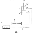
- FIG. 3 shows the air spring or pneumatic element of the isolation strut operational in seismic mode operation.
- the pneumatic chambers 12 and 14 are shown separated by piston 16 which is connected to a piston rod 24.
- the pressure regulator 44 is shown as supplying and receiving air or gas to each of the chambers of the pneumatic cylinder to maintain a specified air pressure within each chamber for proper seismic mode operation, and also are shown the air supply 46 and the air exhaust path 48.
- FIG. 4 shows the hydraulic element of an isolation strut connected for isolation lock-out or isolation modes.
- the hydraulic cylinder is shown having two chambers 20 and 22 separated by piston 18 which is connected to a piston rod 24 which is common to piston 16 of FIGs. 1, 2, and 3. Piston rod 24 would normally be connected to the load to be supported by the isolation strut.
- Ports 34 and 36 are shown cooperating with chambers 20 and 22 respectively.
- a solenoid valve 50 in a hydraulic line 52 which couples the ports 34 and 36 through a manifold 54 which, in turn, is connected to a fluid reservoir 56.
- valve manifold 54 is to provide correspondence between the hydraulic line 52, and thereby ports 34 and 36 and the fluid reservoir 56.
- reservoir 56 is to maintain an adequate source of hydraulic fluid to insure that chambers 20 and 22 remain full at all times.
- the seismic isolation strut 10 integrates an air suspension spring, shown in FIG. 1 as a pneumatic element having air chambers 12 and 14 separated by a piston 16, and a hydraulic element comprising hydraulic chambers 20 and 22 separated by a piston 18, the two hydraulic chambers being coupled through a hydraulic valve 50 (FIG. 4) to provide a stiff foundation for normal operating conditions, a soft suspension system when triggered by seismic activity, and the ability to reset the system quickly and easily following a seismic event.
- an air suspension spring shown in FIG. 1 as a pneumatic element having air chambers 12 and 14 separated by a piston 16, and a hydraulic element comprising hydraulic chambers 20 and 22 separated by a piston 18, the two hydraulic chambers being coupled through a hydraulic valve 50 (FIG. 4) to provide a stiff foundation for normal operating conditions, a soft suspension system when triggered by seismic activity, and the ability to reset the system quickly and easily following a seismic event.
- a hydraulic valve 50 (FIG. 4) is used to lock the hydraulic cylinder and provide a rigid mount for buildings, structures, or equipment. This effectively prevents piston 16 (FIGs. 1 and 2) from moving since even though the gas used in chambers 12 and 14 (FIGs. 1 and 2) is compressible, the incompressibility of the hydraulic fluid within chambers 20 and 22 of the hydraulic cylinder (FIG. 4) and the common connection of piston rod 24 to both pistons 16 and 18 prevents any motion.
- vibration sensor 58 opens solenoid valve 50, allowing piston 18, and thereby, piston 16 to move in response to a force applied to piston rod 24.
- the compressibility of the gas in chambers 12 and 14 absorbs the shock of the vibration, while the hydraulic chambers 20 and 22, in cooperation with piston 18 damp any oscillation of piston 16.
- controller 50 (FIG. 2) senses the position of piston 16 and operates the supply solenoid 40 and the exhaust solenoid 42 to adjust the pressure in the pneumatic chamber 12 such that the length of the isolation strut is adjusted to a predetermined value to move the attached load or platform to a preferred position.
- Hydraulic solenoid 50 is then closed to return the system to its stiff-load condition.
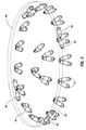
- FIG. 5 shows a plurality of isolation struts 10 as described above supporting a platform 60 upon which may be mounted a building, structure, or other equipment. Although twenty four pairs of struts are shown in FIG. 5, the number of struts is dependent upon the load to be supported.
- the isolation struts may be, as shown, in pairs such that the pairs are mounted at an angle between the earth and the platform so that the common point of the struts supporting the platform provide the necessary freedom to counter vibration in any direction.
- the angle theta between the pairs of struts can be adjusted to provide the stiffness and damping in the rotational and transverse directions desired to allow motion of the platform (in seismic mode) with six degrees of freedom.
- Several pairs of isolation struts 62 may be mounted transversely to compensate for rotational forces around an axis perpendicular to the platform.
- the strut design of FIG. 1 can be implemented with either a single or dual chamber pneumatic spring design While a single chamber design is simpler, a change in chamber volume is required to adjust the spring rate for given static load condition.
- the somewhat more complex dual chamber design, as shown in FIG. 1, provides the ability to adjust the spring rate independently of chamber volume.
- the pneumatic spring implementation which is most desirable would be dependent on the design requirements of the particular problem, including the degree of motion allowed, allowable operating pressures, and the expected need for stiffness adjustability.
Landscapes
- Engineering & Computer Science (AREA)
- General Engineering & Computer Science (AREA)
- Mechanical Engineering (AREA)
- Physics & Mathematics (AREA)
- Acoustics & Sound (AREA)
- Aviation & Aerospace Engineering (AREA)
- Vibration Prevention Devices (AREA)
- Buildings Adapted To Withstand Abnormal External Influences (AREA)
Description
- The present invention relates to a vibration isolation strut, and more particularly to a vibration isolation strut which is rigidly mounted for normal operation but which provides isolation from vibration, particularly seismic vibration.
- In certain applications it is desirable to support a load in such a manner that the support is relatively rigid during normal operation. An example is equipment such as an antenna system for a radar installation, but other examples include buildings, structures, or other equipment. In normal use, a platform supporting the antenna is expected to provide a relatively rigid load path to the ground. Such a support is desirably relatively rigid in order to stabilize the structure for optimum performance and accuracy. Rigid supports, however, can cause damage to the supported structure in the event of violent shaking or vibration such as may be experienced during a seismic event.
- In the past, vibration or motion isolations have generally acted merely to isolate the load or a platform supporting the load from anticipated vibration. Examples of such isolations are found, for example, in the inventions of U.S. Patent 5,803,213, U.S. Patent 5,918,865, and U.S. Patent 5,947,240, all of which are assigned to the assignee of the instant invention. Each of the noted patents relates to load isolation from vibration and each utilizes air suspension springs which are damped by cross-connecting conduits to and from a pair of isolation struts.
- While these devices provide vibration isolation for, for example, isolating a payload from a launch vehicle, they are not intended to provide relatively rigid support for the payload in a first mode of operation and less rigid but damped support in another mode of operation. They are intended, rather, continuously to provide isolation from vibration at all times.
- The devices of the above-identified patents comprise a plurality of load isolation struts, each strut having a pneumatic cylinder, or air suspension spring, with a piston dividing the cylinder into two chambers, and a hydraulic cylinder with a second piston dividing the hydraulic cylinder into two chambers. The air suspension spring provides isolation from vibration and the hydraulic cylinder provides damping of the resulting oscillation of the air spring during vibration.
- Isolation systems incorporating the above devices may comprise pairs of struts placed around the supported load, each strut having its respective hydraulic cylinders cross-coupled to the cylinders of the other strut of the pair.
- While this arrangement is effective in isolating a load from vibration and for damping the effects of any such vibration, the system is intended to operate continuously in the vibration isolation and damping mode.
- FR-A-2671519 discloses a suspension device for a motor vehicle or equivalent.
- US-A-5147018 discloses a cylinder lock device for use in a structure.
- DE8809306U discloses a locking device for commercial motor vehicle springs.
- US-A-5803213 discloses a heavy load vibration isolation apparatus.
- Accordingly, the invention resides in an isolation strut for supporting a load above the ground, the isolation strut comprising:
- a load bearing shaft;
- a hydraulic damping element having a first chamber and a second chamber separated by a piston connected to the load bearing shaft; and
- a hydraulic line having a valve therein, one end of the hydraulic line connected to the first chamber and the other end of the hydraulic line connected to the second chamber,
- the isolation strut further comprises an air suspension spring which is connected to the load bearing shaft;
- the isolation strut is arranged to operate in a first mode of operation, in which the load is rigidly attached to the ground via a structural load path through the hydraulic damping element, and a second mode of operation, in which the load is isolated by the air suspension spring and damped by the hydraulic damping element; and
- the isolation strut further comprises a vibration detector coupled to the valve for actuating the valve upon the occurrence of vibration of an abnormal quality.
- The present invention will hereinafter be described in conjunction with the appended drawing figures, wherein like numerals denote like elements, and:
- FIG. 1 shows an isolation strut usable in the instant invention;
- FIG. 2 shows an air suspension spring element of an isolation strut arranged to allow the isolation strut to be set up or reset for stiff load path operation;
- FIG. 3 shows an air suspension spring element of an isolation strut configured for isolation operation;
- FIG. 4 shows the hydraulic element of an isolation strut connected for isolation lock-out or isolation modes;
- FIG. 5 is a representation of a plurality of isolation struts of the instant invention supporting a platform and allowing stiff mode operation and vibration isolation and damping with six degrees of freedom.
- The following detailed description of a preferred embodiment is merely exemplary in nature and is not intended to limit the invention or the application and uses of the invention.
- A soft suspension system is required for buildings, structures, or equipment to provide isolation from severe vibration conditions, such as seismic activity, to prevent or minimize damage to such buildings, structures, or equipment. However, the buildings, structures, or equipment must otherwise be rigidly mounted for proper operation.
- FIG. 1 shows an
isolation strut 10 usable in the instant invention, having twopneumatic chambers piston 16. Thepiston 16 is connected to asecond piston 18 in a separate hydraulic element having twochambers piston 18. Thepistons piston rod 24 with apivot 26 at the end for attachment to a base. At the other end of theisolation strut 10 is anotherpivot 28 which is connected to a platform or an item to be supported by theisolation strut 10. Each of thepneumatic chambers port hydraulic chamber port - While reference is made to an air suspension spring and to air chambers, it is understood that any compressible gas may be used. Also, appropriate seals (not shown) are used to provide effective isolation between the chambers and between the hydraulic and pneumatic cylinders.
- FIG. 2 is a schematic diagram showing the pneumatic element of the isolation strut with its various controls in set up and reset mode. In setup and reset mode the length of the isolation strut can be adjusted to a predetermined value to move the attached load or platform to a preferred position. The pneumatic portion of the isolation strut, or air suspension spring, is shown with its two
pneumatic chambers piston 16 which defines the two pneumatic chambers, and thepiston rod 24 connected to thepiston 16. Also shown are asupply solenoid 40, anexhaust solenoid 42, and apressure regulator 44 which, in combination, control the gas flow into and out of the twopneumatic chambers ports air supply 46 is shown connected to the pressure regulator and supply solenoid and anair exhaust 48 is connected to the pressure regulator and exhaust solenoid. Acontroller 50 responsive to a position signal from thepiston rod 24, through, perhaps, a linear variable differential transformer turns on or off thesupply solenoid 40 andexhaust solenoid 42 to allow air from the air supply to enter thepneumatic chamber 12 or to exhaust air, or gas, from thepneumatic chamber 12 through anair exhaust 48. Thepressure regulator 44 supplies or exhausts air frompneumatic chamber 14 as required to maintain a specified air pressure within the chamber. The precise operation of FIG. 2 will be described below with respect to the overall operation of the system. - FIG. 3 shows the air spring or pneumatic element of the isolation strut operational in seismic mode operation. Again the
pneumatic chambers piston 16 which is connected to apiston rod 24. Thepressure regulator 44 is shown as supplying and receiving air or gas to each of the chambers of the pneumatic cylinder to maintain a specified air pressure within each chamber for proper seismic mode operation, and also are shown theair supply 46 and theair exhaust path 48. - FIG. 4 shows the hydraulic element of an isolation strut connected for isolation lock-out or isolation modes. The hydraulic cylinder is shown having two
chambers piston 18 which is connected to apiston rod 24 which is common topiston 16 of FIGs. 1, 2, and 3. Pistonrod 24 would normally be connected to the load to be supported by the isolation strut.Ports chambers solenoid valve 50 in ahydraulic line 52 which couples theports manifold 54 which, in turn, is connected to afluid reservoir 56. - Since fluids are relatively incompressible, it is apparent that, when both
chambers solenoid valve 50 is closed thepiston 18, and thereby thepiston rod 24 are immobile. Opening the solenoid valve, however, allows fluid to flow betweenchambers hydraulic line 52 aspiston 18 may be depressed or extended due to an external force being applied to thepiston rod 24. The function of thevalve manifold 54 is to provide correspondence between thehydraulic line 52, and thereby ports 34 and 36 and thefluid reservoir 56. The function ofreservoir 56, of course, is to maintain an adequate source of hydraulic fluid to insure thatchambers - In operation, the
seismic isolation strut 10 integrates an air suspension spring, shown in FIG. 1 as a pneumatic element havingair chambers piston 16, and a hydraulic element comprisinghydraulic chambers piston 18, the two hydraulic chambers being coupled through a hydraulic valve 50 (FIG. 4) to provide a stiff foundation for normal operating conditions, a soft suspension system when triggered by seismic activity, and the ability to reset the system quickly and easily following a seismic event. - For non-earthquake or normal, conditions, a hydraulic valve 50 (FIG. 4) is used to lock the hydraulic cylinder and provide a rigid mount for buildings, structures, or equipment. This effectively prevents piston 16 (FIGs. 1 and 2) from moving since even though the gas used in
chambers 12 and 14 (FIGs. 1 and 2) is compressible, the incompressibility of the hydraulic fluid withinchambers piston rod 24 to bothpistons - Upon the occurrence of a seismic event, however,
vibration sensor 58 openssolenoid valve 50, allowingpiston 18, and thereby,piston 16 to move in response to a force applied topiston rod 24. In such an event, the compressibility of the gas inchambers hydraulic chambers piston 18 damp any oscillation ofpiston 16. - Following a seismic event, the system can be reset as shown in FIG. 2. In order to reset the system, controller 50 (FIG. 2) senses the position of
piston 16 and operates thesupply solenoid 40 and theexhaust solenoid 42 to adjust the pressure in thepneumatic chamber 12 such that the length of the isolation strut is adjusted to a predetermined value to move the attached load or platform to a preferred position..Hydraulic solenoid 50 is then closed to return the system to its stiff-load condition. - FIG. 5 shows a plurality of isolation struts 10 as described above supporting a
platform 60 upon which may be mounted a building, structure, or other equipment. Although twenty four pairs of struts are shown in FIG. 5, the number of struts is dependent upon the load to be supported. The isolation struts may be, as shown, in pairs such that the pairs are mounted at an angle between the earth and the platform so that the common point of the struts supporting the platform provide the necessary freedom to counter vibration in any direction. The angle theta between the pairs of struts can be adjusted to provide the stiffness and damping in the rotational and transverse directions desired to allow motion of the platform (in seismic mode) with six degrees of freedom. Several pairs of isolation struts 62 may be mounted transversely to compensate for rotational forces around an axis perpendicular to the platform. - The strut design of FIG. 1, can be implemented with either a single or dual chamber pneumatic spring design While a single chamber design is simpler, a change in chamber volume is required to adjust the spring rate for given static load condition. The somewhat more complex dual chamber design, as shown in FIG. 1, provides the ability to adjust the spring rate independently of chamber volume. The pneumatic spring implementation which is most desirable would be dependent on the design requirements of the particular problem, including the degree of motion allowed, allowable operating pressures, and the expected need for stiffness adjustability.
- While preferred exemplary embodiments have been presented in the foregoing detailed description of preferred exemplary embodiments, it should be appreciated that a vast number of variations exist. It should also be appreciated that these preferred exemplary embodiments are only examples, and are not intended to limit the scope, applicability, or configuration of the invention in any way. Rather, the ensuing detailed description will provide those skilled in the art with a convenient road map for implementing a preferred embodiment of the invention.
- The invention is defined in the appended claims.
Claims (6)
- An isolation strut (10) for supporting a load above the ground, the isolation strut comprising:a load bearing shaft (24);a hydraulic damping element having a first chamber (20) and a second chamber (22) separated by a piston (18) connected to the load bearing shaft; anda hydraulic line (52) having a valve (50) therein, one end of the hydraulic line connected to the first chamber and the other end of the hydraulic line connected to the second chamber,
characterised in that:the isolation strut further comprises an air suspension spring (12, 14, 16), which is connected to the load bearing shaft;the isolation strut is arranged to operate in a first mode of operation, in which the load is rigidly attached to the ground via a structural load path through the hydraulic damping element, and a second mode of operation, in which the load is isolated by the air suspension spring and damped by the hydraulic damping element; andthe isolation strut further comprises a vibration detector (58) coupled to the valve for actuating the valve upon the occurrence of vibration of an abnormal quality. - An isolation strut (10) according to claim 1, wherein the air suspension spring is a pneumatic cylinder having a piston (16) forming a pair of pneumatic chambers (12, 14).
- An isolation strut (10) according to claim 2, further comprising a source (46) of pneumatic fluid in cooperation with the pneumatic chambers (12, 14) for setting the position of the piston (16) forming the pair of pneumatic chambers.
- An isolation strut (10) according to claim 3, wherein the load is rigidly supported when the position of the piston (16) forming the pair of pneumatic chambers (12, 14) is set.
- An isolation strut (10) according to claim 4, wherein the load is rigidly supported by closing the valve (50) in the hydraulic line (52).
- An isolation strut (10) according to claim 1, wherein:the valve (50) is in series with the hydraulic line (52) and is adapted, during said first mode of operation, to prevent the flow of hydraulic fluid between the two hydraulic chambers (20, 22) whereby the load is rigidly attached to the ground; andthe vibration detector (58) is adapted to open the valve in said second mode of operation upon the occurrence of vibration greater than a prescribed value, such that the load is isolated from the support by the air suspension spring, the action of the air suspension spring being damped by the hydraulic damping element.
Applications Claiming Priority (3)
| Application Number | Priority Date | Filing Date | Title |
|---|---|---|---|
| US125876 | 1993-09-23 | ||
| US10/125,876 US6851529B2 (en) | 2002-04-18 | 2002-04-18 | Multifunction vibration isolation strut |
| PCT/US2003/011628 WO2003089806A1 (en) | 2002-04-18 | 2003-04-15 | Multifunction vibration isolation strut |
Publications (2)
| Publication Number | Publication Date |
|---|---|
| EP1495238A1 EP1495238A1 (en) | 2005-01-12 |
| EP1495238B1 true EP1495238B1 (en) | 2006-08-30 |
Family
ID=29214867
Family Applications (1)
| Application Number | Title | Priority Date | Filing Date |
|---|---|---|---|
| EP03721683A Expired - Lifetime EP1495238B1 (en) | 2002-04-18 | 2003-04-15 | Multifunction vibration isolation strut |
Country Status (5)
| Country | Link |
|---|---|
| US (1) | US6851529B2 (en) |
| EP (1) | EP1495238B1 (en) |
| AU (1) | AU2003224983A1 (en) |
| DE (1) | DE60308005T2 (en) |
| WO (1) | WO2003089806A1 (en) |
Families Citing this family (23)
| Publication number | Priority date | Publication date | Assignee | Title |
|---|---|---|---|---|
| DE10313405A1 (en) * | 2003-03-25 | 2004-10-07 | Zubler Gerätebau GmbH | Dental technology oven for the production of pressed ceramics |
| US20080042331A1 (en) * | 2006-08-18 | 2008-02-21 | Iptrade, Inc. | Dynamic equilibrium air spring for suppressing vibrations |
| US20080041676A1 (en) * | 2006-08-18 | 2008-02-21 | Iptrade, Inc. | Air spring with magneto-rheological fluid gasket for suppressing vibrations |
| US20080079204A1 (en) * | 2006-08-18 | 2008-04-03 | Iptrade, Inc. | Self-aligning air-spring for suppressing vibrations |
| CA2665700C (en) * | 2006-10-12 | 2013-11-19 | Bell Helicopter Textron Inc. | Vibration-attenuating hard-mounted pylon |
| DE202007013300U1 (en) * | 2007-09-21 | 2009-02-12 | Liebherr-Aerospace Lindenberg Gmbh | Active hydraulic damper and hydraulic actuator |
| US8444121B2 (en) * | 2008-03-31 | 2013-05-21 | Honeywell International Inc. | Systems for damping vibrations from a payload |
| US8214178B2 (en) * | 2008-06-04 | 2012-07-03 | Vibration Technologies, Llc | Method and system for optimizing the vibrational characteristics of a structure |
| US8272786B2 (en) * | 2009-02-18 | 2012-09-25 | Honeywell International Inc. | Vibration isolation mounting assembly |
| US8256750B2 (en) * | 2009-02-18 | 2012-09-04 | Honeywell International Inc. | Vibration isolation mounting assembly |
| GB2474030A (en) * | 2009-10-01 | 2011-04-06 | Trysome Ltd | A damper unit for a vehicle suspension system and a vehicle including such a damper unit |
| US8702377B2 (en) | 2010-06-23 | 2014-04-22 | Honeywell International Inc. | Gas turbine engine rotor tip clearance and shaft dynamics system and method |
| DE102011009406A1 (en) * | 2011-01-25 | 2012-07-26 | Dt Swiss Ag | Shock absorber for a bicycle |
| US9062737B2 (en) * | 2012-06-04 | 2015-06-23 | Mclaren Automotive Limited | Shock absorber with four chambers |
| GB201303400D0 (en) | 2013-02-26 | 2013-04-10 | Mclaren Automotive Ltd | Damper unit |
| US10507920B2 (en) * | 2015-05-18 | 2019-12-17 | Sikorsky Aircraft Corp. | Systems and methods for lifting body vibration control |
| CN106763465B (en) * | 2017-03-07 | 2018-08-21 | 江苏大学 | A kind of passive vibration reduction platform of six degree of freedom master |
| GB2566699B (en) * | 2017-09-20 | 2020-02-05 | Jaguar Land Rover Ltd | Active suspension device |
| DE102017128230A1 (en) | 2017-11-29 | 2019-05-29 | Spaleck GmbH & Co. Kommanditgesellschaft | Bearing device for a vibrating machine, vibrating machine and method for operating a vibrating machine |
| MY199588A (en) * | 2018-04-18 | 2023-11-08 | Univ Putra Malaysia | A multipurpose viscous damper |
| DE102018110490A1 (en) * | 2018-05-02 | 2019-11-07 | Dt Swiss Ag | Shock absorber for a bicycle |
| CN108895109A (en) * | 2018-08-31 | 2018-11-27 | 浙江森森汽车零部件有限公司 | The damping of band CDC electronics hybrid active control and air bag suspension assembly |
| DE102024127458A1 (en) * | 2024-09-23 | 2026-03-26 | Thyssenkrupp Ag | Vibration damper for a motor vehicle |
Family Cites Families (15)
| Publication number | Priority date | Publication date | Assignee | Title |
|---|---|---|---|---|
| US2838140A (en) | 1955-11-03 | 1958-06-10 | Marlin B Rasmusson | Hydraulic dash-pot controller for an actuator |
| US4407395A (en) * | 1981-09-25 | 1983-10-04 | Suozzo Leonard S | Mechanical shock and sway arrestor |
| DE8809306U1 (en) | 1988-07-21 | 1988-09-01 | Iveco Magirus AG, 7900 Ulm | Locking device for the vehicle springs of commercial vehicles |
| US5065552A (en) * | 1989-02-07 | 1991-11-19 | Kajima Corporation | Active seismic response control system for use in structure |
| US5147018A (en) * | 1989-03-02 | 1992-09-15 | Kajima Corporation | Cylinder lock device for use in structure |
| FR2671519B1 (en) | 1991-01-15 | 1993-10-08 | Rene Paugam | SUSPENSION DEVICE FOR MOTOR VEHICLE OR EQUIVALENT. |
| JP2603391B2 (en) * | 1991-12-25 | 1997-04-23 | 鹿島建設株式会社 | Variable damping device for damping structures |
| US5497858A (en) * | 1992-08-07 | 1996-03-12 | Robert L. Cloud & Associates, Inc. | Dynamic motion limiter |
| US5595372A (en) * | 1993-03-11 | 1997-01-21 | The Board Of Regents Of The University Of Oklahoma | Semi-active vibration mitigation assembly |
| US5918865A (en) | 1997-01-29 | 1999-07-06 | Honeywell Inc. | Load isolator apparatus |
| US5947240A (en) | 1997-02-03 | 1999-09-07 | Honeywell, Inc. | Load vibration isolation apparatus |
| US5803213A (en) * | 1997-02-03 | 1998-09-08 | Honeywell Inc. | Heavy load vibration isolation apparatus |
| FI104207B (en) | 1998-07-24 | 1999-11-30 | Valmet Corp | A method and apparatus for changing the characteristic frequency of a nip roll structure of a paper or board machine |
| US6193223B1 (en) * | 1998-09-18 | 2001-02-27 | Hartwell Corporation | Dampening strut |
| US6378671B1 (en) * | 2000-03-29 | 2002-04-30 | Lord Corporation | Magnetically actuated motion control device |
-
2002
- 2002-04-18 US US10/125,876 patent/US6851529B2/en not_active Expired - Lifetime
-
2003
- 2003-04-15 AU AU2003224983A patent/AU2003224983A1/en not_active Abandoned
- 2003-04-15 DE DE60308005T patent/DE60308005T2/en not_active Expired - Lifetime
- 2003-04-15 EP EP03721683A patent/EP1495238B1/en not_active Expired - Lifetime
- 2003-04-15 WO PCT/US2003/011628 patent/WO2003089806A1/en not_active Ceased
Also Published As
| Publication number | Publication date |
|---|---|
| US6851529B2 (en) | 2005-02-08 |
| WO2003089806A1 (en) | 2003-10-30 |
| EP1495238A1 (en) | 2005-01-12 |
| AU2003224983A1 (en) | 2003-11-03 |
| DE60308005D1 (en) | 2006-10-12 |
| DE60308005T2 (en) | 2007-02-01 |
| US20030197318A1 (en) | 2003-10-23 |
Similar Documents
| Publication | Publication Date | Title |
|---|---|---|
| US6851529B2 (en) | Multifunction vibration isolation strut | |
| US6196529B1 (en) | Spacecraft antenna vibration control damper | |
| US5803213A (en) | Heavy load vibration isolation apparatus | |
| US6340153B1 (en) | Shock and acoustic mount | |
| EP1848899B1 (en) | Improved isolator using externally pressurized sealing bellows | |
| US3807678A (en) | System for controlling the transmission of energy between spaced members | |
| EP1296082B1 (en) | Dynamically optimized engine suspension system | |
| US9103403B2 (en) | Three parameter, multi-axis isolators, isolation systems employing the same, and methods for producing the same | |
| EP1358082B1 (en) | Vehicle suspension roll control system | |
| US8444121B2 (en) | Systems for damping vibrations from a payload | |
| US3889936A (en) | Combined air mounts | |
| US8888079B2 (en) | Apparatus for improved vibration isolation | |
| US7641181B2 (en) | Distributed power suspension system | |
| CA2279388A1 (en) | Load vibration isolation apparatus | |
| US6547225B1 (en) | Pneumatic isolator with barometric insensitivity | |
| JP3324251B2 (en) | Seismic isolation device | |
| JP2002371725A (en) | 3D vibration isolation device | |
| JP2002106632A (en) | Base isolation device and base isolation structure | |
| US20080041676A1 (en) | Air spring with magneto-rheological fluid gasket for suppressing vibrations | |
| US20080079204A1 (en) | Self-aligning air-spring for suppressing vibrations | |
| Dankowski | Low Frequency Shock and Vibration Isolation for Precision Engineering and Nanotechnology | |
| US20080042331A1 (en) | Dynamic equilibrium air spring for suppressing vibrations | |
| JP2963935B2 (en) | Anti-vibration support device | |
| JP2000038774A (en) | Seismic isolation device, building with seismic isolation device, and method of controlling seismic isolation device operation | |
| GB2298021A (en) | Vibration isolator |
Legal Events
| Date | Code | Title | Description |
|---|---|---|---|
| PUAI | Public reference made under article 153(3) epc to a published international application that has entered the european phase |
Free format text: ORIGINAL CODE: 0009012 |
|
| 17P | Request for examination filed |
Effective date: 20041103 |
|
| AK | Designated contracting states |
Kind code of ref document: A1 Designated state(s): AT BE BG CH CY CZ DE DK EE ES FI FR GB GR HU IE IT LI LU MC NL PT RO SE SI SK TR |
|
| AX | Request for extension of the european patent |
Extension state: AL LT LV MK |
|
| 17Q | First examination report despatched |
Effective date: 20050301 |
|
| GRAP | Despatch of communication of intention to grant a patent |
Free format text: ORIGINAL CODE: EPIDOSNIGR1 |
|
| GRAS | Grant fee paid |
Free format text: ORIGINAL CODE: EPIDOSNIGR3 |
|
| GRAA | (expected) grant |
Free format text: ORIGINAL CODE: 0009210 |
|
| AK | Designated contracting states |
Kind code of ref document: B1 Designated state(s): DE GB |
|
| REG | Reference to a national code |
Ref country code: GB Ref legal event code: FG4D |
|
| REF | Corresponds to: |
Ref document number: 60308005 Country of ref document: DE Date of ref document: 20061012 Kind code of ref document: P |
|
| PLBE | No opposition filed within time limit |
Free format text: ORIGINAL CODE: 0009261 |
|
| STAA | Information on the status of an ep patent application or granted ep patent |
Free format text: STATUS: NO OPPOSITION FILED WITHIN TIME LIMIT |
|
| 26N | No opposition filed |
Effective date: 20070531 |
|
| PGFP | Annual fee paid to national office [announced via postgrant information from national office to epo] |
Ref country code: DE Payment date: 20190430 Year of fee payment: 17 |
|
| PGFP | Annual fee paid to national office [announced via postgrant information from national office to epo] |
Ref country code: GB Payment date: 20190429 Year of fee payment: 17 |
|
| REG | Reference to a national code |
Ref country code: DE Ref legal event code: R119 Ref document number: 60308005 Country of ref document: DE |
|
| PG25 | Lapsed in a contracting state [announced via postgrant information from national office to epo] |
Ref country code: DE Free format text: LAPSE BECAUSE OF NON-PAYMENT OF DUE FEES Effective date: 20201103 |
|
| GBPC | Gb: european patent ceased through non-payment of renewal fee |
Effective date: 20200415 |
|
| PG25 | Lapsed in a contracting state [announced via postgrant information from national office to epo] |
Ref country code: GB Free format text: LAPSE BECAUSE OF NON-PAYMENT OF DUE FEES Effective date: 20200415 |
|
| P01 | Opt-out of the competence of the unified patent court (upc) registered |
Effective date: 20230525 |