EP1494887B1 - Powertrain for motor vehicle - Google Patents
Powertrain for motor vehicle Download PDFInfo
- Publication number
- EP1494887B1 EP1494887B1 EP03710583A EP03710583A EP1494887B1 EP 1494887 B1 EP1494887 B1 EP 1494887B1 EP 03710583 A EP03710583 A EP 03710583A EP 03710583 A EP03710583 A EP 03710583A EP 1494887 B1 EP1494887 B1 EP 1494887B1
- Authority
- EP
- European Patent Office
- Prior art keywords
- engine
- torque
- gear
- powertrain
- engaged
- Prior art date
- Legal status (The legal status is an assumption and is not a legal conclusion. Google has not performed a legal analysis and makes no representation as to the accuracy of the status listed.)
- Expired - Lifetime
Links
Images


Classifications
-
- B—PERFORMING OPERATIONS; TRANSPORTING
- B60—VEHICLES IN GENERAL
- B60W—CONJOINT CONTROL OF VEHICLE SUB-UNITS OF DIFFERENT TYPE OR DIFFERENT FUNCTION; CONTROL SYSTEMS SPECIALLY ADAPTED FOR HYBRID VEHICLES; ROAD VEHICLE DRIVE CONTROL SYSTEMS FOR PURPOSES NOT RELATED TO THE CONTROL OF A PARTICULAR SUB-UNIT
- B60W10/00—Conjoint control of vehicle sub-units of different type or different function
- B60W10/04—Conjoint control of vehicle sub-units of different type or different function including control of propulsion units
- B60W10/06—Conjoint control of vehicle sub-units of different type or different function including control of propulsion units including control of combustion engines
-
- B—PERFORMING OPERATIONS; TRANSPORTING
- B60—VEHICLES IN GENERAL
- B60W—CONJOINT CONTROL OF VEHICLE SUB-UNITS OF DIFFERENT TYPE OR DIFFERENT FUNCTION; CONTROL SYSTEMS SPECIALLY ADAPTED FOR HYBRID VEHICLES; ROAD VEHICLE DRIVE CONTROL SYSTEMS FOR PURPOSES NOT RELATED TO THE CONTROL OF A PARTICULAR SUB-UNIT
- B60W10/00—Conjoint control of vehicle sub-units of different type or different function
- B60W10/02—Conjoint control of vehicle sub-units of different type or different function including control of driveline clutches
-
- B—PERFORMING OPERATIONS; TRANSPORTING
- B60—VEHICLES IN GENERAL
- B60W—CONJOINT CONTROL OF VEHICLE SUB-UNITS OF DIFFERENT TYPE OR DIFFERENT FUNCTION; CONTROL SYSTEMS SPECIALLY ADAPTED FOR HYBRID VEHICLES; ROAD VEHICLE DRIVE CONTROL SYSTEMS FOR PURPOSES NOT RELATED TO THE CONTROL OF A PARTICULAR SUB-UNIT
- B60W10/00—Conjoint control of vehicle sub-units of different type or different function
- B60W10/10—Conjoint control of vehicle sub-units of different type or different function including control of change-speed gearings
- B60W10/11—Stepped gearings
- B60W10/111—Stepped gearings with separate change-speed gear trains arranged in series
-
- B—PERFORMING OPERATIONS; TRANSPORTING
- B60—VEHICLES IN GENERAL
- B60W—CONJOINT CONTROL OF VEHICLE SUB-UNITS OF DIFFERENT TYPE OR DIFFERENT FUNCTION; CONTROL SYSTEMS SPECIALLY ADAPTED FOR HYBRID VEHICLES; ROAD VEHICLE DRIVE CONTROL SYSTEMS FOR PURPOSES NOT RELATED TO THE CONTROL OF A PARTICULAR SUB-UNIT
- B60W30/00—Purposes of road vehicle drive control systems not related to the control of a particular sub-unit, e.g. of systems using conjoint control of vehicle sub-units, or advanced driver assistance systems for ensuring comfort, stability and safety or drive control systems for propelling or retarding the vehicle
- B60W30/18—Propelling the vehicle
- B60W30/184—Preventing damage resulting from overload or excessive wear of the driveline
-
- F—MECHANICAL ENGINEERING; LIGHTING; HEATING; WEAPONS; BLASTING
- F02—COMBUSTION ENGINES; HOT-GAS OR COMBUSTION-PRODUCT ENGINE PLANTS
- F02D—CONTROLLING COMBUSTION ENGINES
- F02D41/00—Electrical control of supply of combustible mixture or its constituents
- F02D41/02—Circuit arrangements for generating control signals
- F02D41/021—Introducing corrections for particular conditions exterior to the engine
- F02D41/0215—Introducing corrections for particular conditions exterior to the engine in relation with elements of the transmission
- F02D41/0225—Introducing corrections for particular conditions exterior to the engine in relation with elements of the transmission in relation with the gear ratio or shift lever position
-
- B—PERFORMING OPERATIONS; TRANSPORTING
- B60—VEHICLES IN GENERAL
- B60W—CONJOINT CONTROL OF VEHICLE SUB-UNITS OF DIFFERENT TYPE OR DIFFERENT FUNCTION; CONTROL SYSTEMS SPECIALLY ADAPTED FOR HYBRID VEHICLES; ROAD VEHICLE DRIVE CONTROL SYSTEMS FOR PURPOSES NOT RELATED TO THE CONTROL OF A PARTICULAR SUB-UNIT
- B60W2710/00—Output or target parameters relating to a particular sub-units
- B60W2710/06—Combustion engines, Gas turbines
- B60W2710/0666—Engine torque
-
- F—MECHANICAL ENGINEERING; LIGHTING; HEATING; WEAPONS; BLASTING
- F02—COMBUSTION ENGINES; HOT-GAS OR COMBUSTION-PRODUCT ENGINE PLANTS
- F02D—CONTROLLING COMBUSTION ENGINES
- F02D2250/00—Engine control related to specific problems or objectives
- F02D2250/18—Control of the engine output torque
- F02D2250/26—Control of the engine output torque by applying a torque limit
-
- F—MECHANICAL ENGINEERING; LIGHTING; HEATING; WEAPONS; BLASTING
- F16—ENGINEERING ELEMENTS AND UNITS; GENERAL MEASURES FOR PRODUCING AND MAINTAINING EFFECTIVE FUNCTIONING OF MACHINES OR INSTALLATIONS; THERMAL INSULATION IN GENERAL
- F16H—GEARING
- F16H61/00—Control functions within control units of change-speed- or reversing-gearings for conveying rotary motion ; Control of exclusively fluid gearing, friction gearing, gearings with endless flexible members or other particular types of gearing
- F16H61/70—Control functions within control units of change-speed- or reversing-gearings for conveying rotary motion ; Control of exclusively fluid gearing, friction gearing, gearings with endless flexible members or other particular types of gearing specially adapted for change-speed gearing in group arrangement, i.e. with separate change-speed gear trains arranged in series, e.g. range or overdrive-type gearing arrangements
Definitions
- the present invention relates to a powertrain comprising an internal combustion engine and a stagegeared gearbox connected to the engine crankshaft by way of a multi-disc clutch. At least one control element controls and regulates at least the engine.
- a manufacturer of internal combustion engines usually optimizes an engine design in order to achieve a certain engine power output, low fuel consumption, good efficiency and high torque.
- software incorporated into the engine control unit in a certain way, it is possible to precisely determine the appearance of an engine torque and speed curve, that is to say what maximum torque the engine must be capable of delivering at a certain number of revolutions. This is done, in a supercharged engine (exhaust turbocharger or compressor driven by the crankshaft), for example, by controlling the boost pressure in such a way that a certain maximum torque is obtained at a certain number of revolutions.
- the design dimensions of the engine hardware naturally impose purely physical or strength limits on what the engine can on the whole deliver.
- the manufacturer selects a torque and engine speed curve of a certain appearance for a particular engine model according to which the engine is allowed to deliver its maximum torque.
- the vehicle transmission should be shifted up or down so that the engine torque can be better utilized.
- the gearing between the engine and the vehicle's driving wheels is adjusted so that the engine speed attains a level for which the corresponding maximum torque is sufficient.
- the engine and the gearbox form the vehicle powertrain.
- a stagegeared gearbox usually comprises an input shaft, an intermediate shaft, which has at least one toothed gear meshing with a toothed gear on the input shaft, and main shaft with toothed gears, which mesh with toothed gears on the intermediate shaft.
- the main shaft is then further connected to an output shaft coupled to the driving wheels by way of a prop shaft, for example.
- Each pair of toothed gears has a different gear ratio from another pair of gears in the gearbox. Different transmission ratios are obtained in that different pairs of gears transmit the torque from the engine to the driving wheels. Between two interacting and rotating toothed gears in a gearbox friction losses occur between the teeth of each of the toothed gears which are in engagement.
- the highest gear is a so-called direct gear.
- the input shaft and the main shaft (or the output shaft) in the gearbox are directly connected to one another when the direct gear is engaged, which means that the torque is transmitted straight through the gearbox without any gearing.
- the transmission ratio is 1:1. Consequently no losses occur between meshing gears.
- the direct gear is, all in all, a more fuel-saving gear than the other indirect gears, the transmission ratios of which are obtained through the pairs of toothed gears.
- Driving a vehicle in a direct gear saves fuel in that friction losses in the gearbox are lower.
- the vehicle may begin to slow down due to the fact that the maximum torque from the engine is not sufficient to keep the vehicle speed constant.
- an automatic stagegeared gearbox will change down to a lower gear (higher gear ratio). Owing to the new higher gearing of the engine torque, the powertrain will now hopefully be able to deliver a sufficient torque to the driving wheels to be at least capable of maintaining a somewhat slower speed.
- the equivalent can be said to occur in the case of brief braking in which the speed reduction does not directly cause changing down, but the vehicle speed after braking is such that the corresponding engine speed and maximum torque with the direct gear engaged are insufficient and the vehicle begins to decelerate and the gearbox will then change down.
- US 5876302 which discloses the features of the preamble of claim 1, shows an arrangement in which the engine control unit permits a higher engine output torque when a direct gear in a stagegeared gearbox is engaged.
- the object according to this arrangement is to utilize the greater strength of the direct gear.
- the engine control unit allows a higher maximum permitted drive torque output from the engine.
- US 5679096 shows an arrangement in which a stagegeared gearbox is equipped with direct gear and so-called overdrive gears enhanced from the strength standpoint (that is to say overdrive gear in which the transmission ratio between the rotational speed of the gearbox input and output shafts is less than 1:1). In this way a higher maximum permitted engine output torque can be allowed for the direct gear and the overdrive gears compared to the lower gears.
- the control unit receives an input signal indicating that a direct gear or overdrive gear is engaged, the engine control unit allows a higher maximum permitted output drive torque from the engine.
- the arrangement according to the invention relates to a powertrain for motor vehicles, comprising an internal combustion engine and an input shaft to a stagegeared gearbox connected to the engine crankshaft by way of a multi-disc clutch, the gearbox having at least one direct gear and at least one indirect gear with intermeshing toothed gears.
- a control element having at least one engine control function is arranged in the vehicle, the control element registering input signals representing the gear selected and various engine and vehicle data, which as a minimum cover the engine speed or revolutions of the input shaft or the vehicle speed.
- the control element is designed, in response to an input signal indicating that a direct gear is engaged, to be capable of controlling and/or regulating the engine so that the engine can deliver a higher maximum permitted torque than when the direct gear is not engaged.
- control element is designed to allow the increase in the maximum permitted torque only if the efficiency of the gearbox or powertrain with direct gear engaged and increased maximum permitted engine output torque is superior to the efficiency of the gearbox or powertrain when any of the indirect gears having a lower maximum permitted engine output torque are engaged.
- the increase in the maximum permitted engine output torque with direct gear engaged is only allowed if the vehicle fuel consumption does not increase due to the increase in the torque. If the efficiency with increased engine torque is inferior, the control element elects not to increase the maximum permitted engine output torque with direct gear engaged. Thus the engine output torque will be insufficient and the control element will therefore change down to a gear affording greater efficiency.
- the advantage to this is that it achieves greater efficiency of the vehicle, that is to say a lower overall fuel consumption.
- the overall efficiency of the vehicle is further improved compared to the prior art if the efficiency comparison is based on the efficiency of the powertrain.
- the function in which the efficiencies are compared is suitably integrated into the programmed gear selection strategy of the transmission control unit.
- control element is designed to regulate the engine so that the increased maximum torque is applied in one step and/or continuously owing to the fact that the vehicle is not allowed to accelerate through the delivery of extra fuel.
- the increase in the torque is not allowed to deliver a power boost, which can cause the vehicle to surge away.
- the driver can summon up acceleration only by depressing the accelerator pedal further, or alternatively by adjusting the setting on the cruise control. Acceleration through the supply of fuel (as distinct from acceleration due to gravity, for example) can only occur at the normal maximum engine torque, that is to say not under increased torque. The reason for this is that the engine consumes a relatively large amount of fuel in acceleration at increased maximum torque.
- the increase can be adjusted whilst underway so that the vehicle does not actually accelerate but does not slow down either, the engine instead being able to maintain the speed with the direct gear engaged.
- One alternative is to increase or reduce the maximum torque in one or more stages. According to an alternative embodiment the increase in the maximum torque only occurs when the vehicle is decelerating.
- the increase in the maximum torque only occurs on condition that the mean speed of the vehicle does not increase in comparison to what it would be if the maximum torque were not increased.
- An increased speed means, for example, that the air resistance of the vehicle increases with the square of the corresponding speed increase.
- 1 denotes a six-cylinder internal combustion engine, for example a diesel engine, the crankshaft 2 of which is coupled to a single-plate dry multi-disc clutch generally denoted by 3, which is enclosed in a clutch cover 4.
- a two-plate clutch may be used.
- the crankshaft 2 is rotationally fixed by way of the engine output shaft 51 (see figure 2) to the clutch housing 5 of the clutch 13 while the plate 6 thereof is rotationally fixed to an input shaft 7, which is rotatably supported in the housing 8 of a gearbox generally denoted by 9.
- a main shaft 10 and an intermediate shaft 11 are also rotatably supported in the housing 8.
- an engine control unit 48 Also illustrated are an engine control unit 48, a transmission control unit 45 and a manual gear selector 46, coupled to the transmission control unit 45.
- the transmission control unit 45 and the engine control unit 48 are adapted for communication with one another.
- a gear 12 is rotatably supported on the input shaft 7 and can be locked to the shaft by means of a clutch sleeve 13 provided with synchromesh elements, the sleeve being supported so that it cannot rotate but is axially displaceable on a hub 14 rotationally fixed to the input shaft.
- a gear 15, rotatably supported on the main shaft 10 can also be locked in relation to the input shaft 7 by means of the clutch sleeve 13. With the clutch sleeve 13 in a central position both of the toothed gears 12 and 15 are disengaged from their respective shafts 7 and 10. The toothed gears 12 and 15 mesh with toothed gears 16 and 17 respectively, which are rotationally fixed to the intermediate shaft 11.
- Rotationally fixed to the intermediate shaft 11 are further toothed gears 18, 19 and 20, which mesh respectively with gears 21, 22 and 23, which are rotatably supported on the main shaft 10 and can be locked to the main shaft by means of clutch sleeves 24 and 25 respectively, which in the exemplary embodiment are shown without synchromesh arrangements.
- a further toothed gear 28 is rotatably supported on the main shaft 10 and meshes with an intermediate toothed gear 30 which is rotatably supported on a separate shaft 29 and in turn meshes with the intermediate shaft toothed gear 20.
- the toothed gear 28 can be locked to its shaft by means of a clutch sleeve 26.
- the gear pairs 12,16 and 15,17 and the clutch sleeve 13 form a splitter group with a low transmission stage LS and a high transmission stage HS.
- the gear pair 15, 17, together with the gear pairs 21, 18, 22, 19, 23, 20 and 28, 30 also form a main gearbox with four forward gears and one reverse gear.
- Rotationally fixed to the output end of the main shaft is a toothed gear 31, which forms the sun gear in a two-speed range transmission of planetary type denoted by 32, the planet wheel carrier 33 of which is rotationally fixed to a shaft 34, which forms the gearbox output shaft.
- the planet wheel 35 of the range transmission 32 meshes with an annular gear 36, which by means of a clutch sleeve 37 can be locked in relation to the gearbox housing 8 for low range LR and in relation to the planet wheel carrier 33 for high range HR.
- the clutch sleeves 13, 24, 25, 26 and 37 are displaceable as indicated by the arrows in figure 2, thereby obtaining the transmission stages shown next to the arrows.
- the displacement is achieved by servo devices 40, 41, 42, 43 and 44 shown schematically in figure 2, which may be pneumatically actuated piston-cylinder arrangements of the type used in a gearbox of the type described above, which is marketed under the designation Geartronic®.
- the servo devices 40, 41, 42, 43 and 44 are controlled by a transmission control unit 45 (see figure 1), comprising a microprocessor, as a function of signals fed into the control unit and representing various engine and vehicle data covering at least the engine speed, vehicle speed, accelerator pedal position and, where applicable, engine brake off/on, when an electronic gear selector 46 coupled to the control unit 45 is in its automatic shift position.
- gear shifting is performed at the driver's command via the gear selector 46.
- the control unit 45 also controls the fuel injection, that is to say the engine speed, as a function of the accelerator pedal position and the air admission to a pneumatic piston-cylinder arrangement 47, by means of which the multi-disc clutch 3 is disengaged or engaged.
- the direct gear in the gearbox 9 is engaged when gear 4HS is engaged and when the range transmission 32 has the high-range position HR engaged.
- Gear 4HS is engaged when the clutch sleeve for the splitter group 13 is in its high transmission stage HS and the clutch sleeve 24 locks the gear 15 to the shaft 10, i.e. the clutch sleeve 24 is carried to the left in figure 2.
- the gearbox main shaft 10 is directly coupled to the gearbox output shaft 34. The torque from the engine 1 therefore passes straight through the entire gearbox in that the shafts 51 and 10 are directly coupled together and the shafts 10 and 34 are coupled together.
- Figure 3 shows the necessary torque that is basically required on the gearbox output shaft 34 in order to cope with an assumed rolling resistance. This is shown by the horizontal line (required torque (Nm)), which according to the example in figure 3 is in the order of approximately 2100 Nm.
- the rotational speed in figure 3 shows the rotational speed of the gearbox output shaft 34.
- the maximum engine torque normally permitted with the direct gear engaged is illustrated by the curve (direct gear) shown by a solid line, which at 600 rpm shows a maximum of 1000 Nm.
- the control unit 45 will therefore ensure that the gearbox changes down to the next lower gear, that is to say an indirect gear.
- the engine 1 By changing down, the engine 1 will be able to deliver a torque curve on the gearbox output shaft 34 corresponding to the curve with a dashed line (indirect gear), which at 400 rpm shows a maximum of 1250 Nm.
- dashed line indirect gear
- changing down gives a torque sufficient to cope with the required level if the rotational speed on the gearbox output shaft 34 remains between approximately 700 and slightly more than 1400 rpm.
- By allowing the engine to deliver an increased torque in accordance with the invention in this case increased between 1000 and slightly more than 1600 rpm (see dashed curve issuing from the "direct gear” curve), it is possible, even when the direct gear is engaged, to reach the required level in the example shown of between 1000 and slightly more than 1400 rpm. This means that the torque is sufficient to prevent the vehicle from decelerating and the vehicle can therefore continue to be driven in the direct gear, with the advantage that fuel will be saved due to the lower friction losses.
- Figure 4 is a diagram basically showing how the overall efficiency of an engine 1 varies as a function of the engine torque and engine speed. It can be seen, for example, that the engine efficiency in the example shown is just over 42.5 % at 1400 rpm and 1400 Nm.
- the term overall efficiency of a powertrain is taken to mean the efficiency for a combination of engine 1 and gearbox 9 in a given driving situation, that is to say a given speed and given motive force.
- an indirect gear gives an approximately 2% lower efficiency than in driving in a direct gear.
- Corresponding information to that in the diagram according to figure 4 and the two per cent "gear toothing engagement" losses is stored in a memory unit in the transmission control unit 45.
- the transmission control unit 45 controls which gear is to be engaged next time. The comparison can be made with the next lower indirect gear to the direct gear or with multiple indirect gears simultaneously. If the overall efficiency for an indirect gear proves to be better than with direct gear engaged, the transmissions control unit 45 will give an instruction to change down to the indirect gear. If the efficiency is better when the direct gear with increased maximum engine torque is engaged, the direct gear will continue to be engaged.
- the efficiency of the gearbox 9 alone can be used instead of the efficiency of the powertrain. This gives a simplified calculation, but also a somewhat inferior basis for the gear selection decision.
- the increase in the maximum engine torque when driving in the direct gear can be applied either irrespective of power output limits or as a function thereof.
- one embodiment can proceed from the assumption that the specified maximum power output of the engine will remain unchanged.
- the transmissions control unit 45 can be programmed to reduce the maximum torque that the engine 1 can deliver in all indirect gears, while maintaining normal maximum torque in the direct gear.
- control units 45 and 48 may be performed by a single control unit or by more than two control units.
- the invention is naturally applicable to a gearbox without splitter group and/or without range transmission.
- the invention is furthermore applicable both to automatic stagegeared gearboxes and manual stagegeared gearboxes.
Abstract
Description
- The present invention relates to a powertrain comprising an internal combustion engine and a stagegeared gearbox connected to the engine crankshaft by way of a multi-disc clutch. At least one control element controls and regulates at least the engine.
- Automatic gearboxes of the automated stagegeared gearbox type have become ever more common in heavier vehicles with the increasing development of microprocessor systems, making it possible, with a control computer and a number of control devices, such as servomotors, for example, to precisely regulate the engine speed, engagement and disengagement of an automatic clutch between engine and gearbox, and gearbox clutch members in relation to one another, so that smooth gear changes are always achieved at the correct engine speed. The advantage with this type of automatic gearbox compared to a conventional automatic gearbox made up of planetary gear trains and having a hydrodynamic torque converter on the inlet side lies partly in the fact that it is simpler and more robust and can be manufactured at substantially lower cost than the conventional automatic gearbox, especially where used in heavy vehicles, and partly in that it affords greater efficiency, which means scope for reduced fuel consumption.
- The development of computer technology has also had an impact on electronic control and feedback systems for a vehicle engine, and these systems have become more precise, faster and more adaptable to prevailing engine and environmental conditions. The entire combustion process can be precisely controlled according to any operating situation. Mention should also be made here of various sensors for the detection of parameters essential for engine feedback and control.
- A manufacturer of internal combustion engines usually optimizes an engine design in order to achieve a certain engine power output, low fuel consumption, good efficiency and high torque. By designing software incorporated into the engine control unit in a certain way, it is possible to precisely determine the appearance of an engine torque and speed curve, that is to say what maximum torque the engine must be capable of delivering at a certain number of revolutions. This is done, in a supercharged engine (exhaust turbocharger or compressor driven by the crankshaft), for example, by controlling the boost pressure in such a way that a certain maximum torque is obtained at a certain number of revolutions. The design dimensions of the engine hardware naturally impose purely physical or strength limits on what the engine can on the whole deliver. The manufacturer selects a torque and engine speed curve of a certain appearance for a particular engine model according to which the engine is allowed to deliver its maximum torque.
- If, in driving the vehicle, the engine speed rises or falls to such an extent that the maximum engine torque is insufficient, the vehicle transmission (gearbox) should be shifted up or down so that the engine torque can be better utilized. By means of gearboxes as described above, the gearing between the engine and the vehicle's driving wheels is adjusted so that the engine speed attains a level for which the corresponding maximum torque is sufficient. The engine and the gearbox form the vehicle powertrain.
- A stagegeared gearbox usually comprises an input shaft, an intermediate shaft, which has at least one toothed gear meshing with a toothed gear on the input shaft, and main shaft with toothed gears, which mesh with toothed gears on the intermediate shaft. The main shaft is then further connected to an output shaft coupled to the driving wheels by way of a prop shaft, for example. Each pair of toothed gears has a different gear ratio from another pair of gears in the gearbox. Different transmission ratios are obtained in that different pairs of gears transmit the torque from the engine to the driving wheels. Between two interacting and rotating toothed gears in a gearbox friction losses occur between the teeth of each of the toothed gears which are in engagement.
- In some stagegeared gearboxes the highest gear (lowest gear ratio) is a so-called direct gear. This implies that the input shaft and the main shaft (or the output shaft) in the gearbox are directly connected to one another when the direct gear is engaged, which means that the torque is transmitted straight through the gearbox without any gearing. It may alternatively be said that the transmission ratio is 1:1. Consequently no losses occur between meshing gears. In other words the direct gear is, all in all, a more fuel-saving gear than the other indirect gears, the transmission ratios of which are obtained through the pairs of toothed gears.
- Driving a vehicle in a direct gear saves fuel in that friction losses in the gearbox are lower. When the vehicle encounters a sufficiently increased rolling resistance, due to a steeper uphill gradient, for example, or increasing headwind, the vehicle may begin to slow down due to the fact that the maximum torque from the engine is not sufficient to keep the vehicle speed constant.
- In order to obtain greater motive force on the vehicle's driving wheels, an automatic stagegeared gearbox will change down to a lower gear (higher gear ratio). Owing to the new higher gearing of the engine torque, the powertrain will now hopefully be able to deliver a sufficient torque to the driving wheels to be at least capable of maintaining a somewhat slower speed.
- The equivalent can be said to occur in the case of brief braking in which the speed reduction does not directly cause changing down, but the vehicle speed after braking is such that the corresponding engine speed and maximum torque with the direct gear engaged are insufficient and the vehicle begins to decelerate and the gearbox will then change down.
- Whilst the direct gear is fuel-saving, it is usually at the same time also the most powerful from the strength point of view, that is to say it manages to transmit higher torque than other gears in which the torque is transmitted via the toothing systems on the toothed gears meshing in the gear pair for each particular gear.
-
US 5876302 which discloses the features of the preamble of claim 1, shows an arrangement in which the engine control unit permits a higher engine output torque when a direct gear in a stagegeared gearbox is engaged. The object according to this arrangement is to utilize the greater strength of the direct gear. As soon as the control unit receives an input signal indicating that a direct gear is engaged, the engine control unit allows a higher maximum permitted drive torque output from the engine. -
US 5679096 shows an arrangement in which a stagegeared gearbox is equipped with direct gear and so-called overdrive gears enhanced from the strength standpoint (that is to say overdrive gear in which the transmission ratio between the rotational speed of the gearbox input and output shafts is less than 1:1). In this way a higher maximum permitted engine output torque can be allowed for the direct gear and the overdrive gears compared to the lower gears. When the control unit receives an input signal indicating that a direct gear or overdrive gear is engaged, the engine control unit allows a higher maximum permitted output drive torque from the engine. - In the prior art, driving with direct gear and an increase in the maximum permitted engine output torque does not necessarily mean that the vehicle is being driven with greater fuel economy than if the vehicle were driven with an indirect gear with a lower maximum permitted engine output torque. There is therefore a need to reduce the fuel consumption of vehicles in which the vehicle engine with direct gear engaged can deliver an increased maximum permitted torque. This is the primary object of the invention described below.
- According to the invention this object is achieved by the solution described in claim 1, with due reference to the arrangement according to the invention. Claims 2 to 6 describe preferred embodiments and developments of the arrangement according to the invention.
- The arrangement according to the invention relates to a powertrain for motor vehicles, comprising an internal combustion engine and an input shaft to a stagegeared gearbox connected to the engine crankshaft by way of a multi-disc clutch, the gearbox having at least one direct gear and at least one indirect gear with intermeshing toothed gears. A control element having at least one engine control function is arranged in the vehicle, the control element registering input signals representing the gear selected and various engine and vehicle data, which as a minimum cover the engine speed or revolutions of the input shaft or the vehicle speed. The control element is designed, in response to an input signal indicating that a direct gear is engaged, to be capable of controlling and/or regulating the engine so that the engine can deliver a higher maximum permitted torque than when the direct gear is not engaged. The arrangement is characterized in that the control element is designed to allow the increase in the maximum permitted torque only if the efficiency of the gearbox or powertrain with direct gear engaged and increased maximum permitted engine output torque is superior to the efficiency of the gearbox or powertrain when any of the indirect gears having a lower maximum permitted engine output torque are engaged.
- Thus the increase in the maximum permitted engine output torque with direct gear engaged is only allowed if the vehicle fuel consumption does not increase due to the increase in the torque. If the efficiency with increased engine torque is inferior, the control element elects not to increase the maximum permitted engine output torque with direct gear engaged. Thus the engine output torque will be insufficient and the control element will therefore change down to a gear affording greater efficiency.
- The advantage to this is that it achieves greater efficiency of the vehicle, that is to say a lower overall fuel consumption. The overall efficiency of the vehicle is further improved compared to the prior art if the efficiency comparison is based on the efficiency of the powertrain. The function in which the efficiencies are compared is suitably integrated into the programmed gear selection strategy of the transmission control unit.
- Further advantages of the arrangement according to the invention are that when the vehicle is driven more with a direct gear engaged, fuel savings are achieved because the overall friction losses are lower. This is possible due to the fact that the control element for engine and gearbox is programmed in such a way that the engine has scope to deliver a higher maximum torque only when a direct gear is engaged. In this way the engine is able to maintain the vehicle speed in many driving situations. The gearbox need not change down until later, or in some cases not at all if the increased torque continues to suffice for the future rolling resistance. A further advantage is that increased driving with the direct gear engaged gives a longer gearbox service life, since no toothed gears in the gearbox are under load when the direct gear is engaged.
- According to an advantageous first embodiment of the arrangement according to the invention the control element is designed to regulate the engine so that the increased maximum torque is applied in one step and/or continuously owing to the fact that the vehicle is not allowed to accelerate through the delivery of extra fuel.
- This has advantages in terms both of safety and fuel economy. The increase in the torque is not allowed to deliver a power boost, which can cause the vehicle to surge away. The driver can summon up acceleration only by depressing the accelerator pedal further, or alternatively by adjusting the setting on the cruise control. Acceleration through the supply of fuel (as distinct from acceleration due to gravity, for example) can only occur at the normal maximum engine torque, that is to say not under increased torque. The reason for this is that the engine consumes a relatively large amount of fuel in acceleration at increased maximum torque. By continuously increasing the maximum torque, the increase can be adjusted whilst underway so that the vehicle does not actually accelerate but does not slow down either, the engine instead being able to maintain the speed with the direct gear engaged. One alternative is to increase or reduce the maximum torque in one or more stages. According to an alternative embodiment the increase in the maximum torque only occurs when the vehicle is decelerating.
- According to an advantageous second embodiment of the arrangement according to the invention the increase in the maximum torque only occurs on condition that the mean speed of the vehicle does not increase in comparison to what it would be if the maximum torque were not increased.
- The advantage to this is that unnecessary speed increases are avoided. An increased speed means, for example, that the air resistance of the vehicle increases with the square of the corresponding speed increase.
- Further advantageous embodiments of the invention are set forth in the succeeding dependent claims.
- The present invention will be described in more detail below with reference to the drawings attached, which by way of example show further preferred embodiments of the invention and the technical background of the invention.
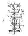
- Figure 1 shows a schematic diagram of an embodiment of a powertrain according to the invention.
- Figure 2 shows the clutch and the gearbox in figure 1 on a larger scale.
- Figure 3 is a diagram basically showing how the maximum torque varies with the rotational speed of the gearbox output shaft. The magnitude of the torque and the rotational speed in the figure is shown only by way of example.
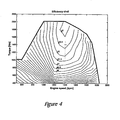
- Figure 4 is a triaxial diagram basically showing how the overall efficiency of an engine varies as a function of the engine torque and engine speed. The magnitude of the efficiency, torque and rotational speed in the figure is shown only by way of example.
- In figure 1, 1 denotes a six-cylinder internal combustion engine, for example a diesel engine, the crankshaft 2 of which is coupled to a single-plate dry multi-disc clutch generally denoted by 3, which is enclosed in a clutch cover 4. Instead of a single-plate multi-disc clutch a two-plate clutch may be used. The crankshaft 2 is rotationally fixed by way of the engine output shaft 51 (see figure 2) to the clutch housing 5 of the clutch 13 while the
plate 6 thereof is rotationally fixed to an input shaft 7, which is rotatably supported in thehousing 8 of a gearbox generally denoted by 9. Amain shaft 10 and an intermediate shaft 11 are also rotatably supported in thehousing 8. Also illustrated are anengine control unit 48, atransmission control unit 45 and amanual gear selector 46, coupled to thetransmission control unit 45. Thetransmission control unit 45 and theengine control unit 48 are adapted for communication with one another. - As will be most clearly seen from figure 2, a
gear 12 is rotatably supported on the input shaft 7 and can be locked to the shaft by means of aclutch sleeve 13 provided with synchromesh elements, the sleeve being supported so that it cannot rotate but is axially displaceable on ahub 14 rotationally fixed to the input shaft. Agear 15, rotatably supported on themain shaft 10, can also be locked in relation to the input shaft 7 by means of theclutch sleeve 13. With theclutch sleeve 13 in a central position both of the toothed gears 12 and 15 are disengaged from theirrespective shafts 7 and 10. The toothed gears 12 and 15 mesh withtoothed gears 16 and 17 respectively, which are rotationally fixed to the intermediate shaft 11. Rotationally fixed to the intermediate shaft 11 are furthertoothed gears gears main shaft 10 and can be locked to the main shaft by means ofclutch sleeves 24 and 25 respectively, which in the exemplary embodiment are shown without synchromesh arrangements. A furthertoothed gear 28 is rotatably supported on themain shaft 10 and meshes with an intermediatetoothed gear 30 which is rotatably supported on aseparate shaft 29 and in turn meshes with the intermediate shafttoothed gear 20. Thetoothed gear 28 can be locked to its shaft by means of aclutch sleeve 26. - The gear pairs 12,16 and 15,17 and the
clutch sleeve 13 form a splitter group with a low transmission stage LS and a high transmission stage HS. Thegear pair 15, 17, together with the gear pairs 21, 18, 22, 19, 23, 20 and 28, 30 also form a main gearbox with four forward gears and one reverse gear. Rotationally fixed to the output end of the main shaft is atoothed gear 31, which forms the sun gear in a two-speed range transmission of planetary type denoted by 32, theplanet wheel carrier 33 of which is rotationally fixed to ashaft 34, which forms the gearbox output shaft. Theplanet wheel 35 of therange transmission 32 meshes with anannular gear 36, which by means of aclutch sleeve 37 can be locked in relation to thegearbox housing 8 for low range LR and in relation to theplanet wheel carrier 33 for high range HR. - The
clutch sleeves servo devices 40, 41, 42, 43 and 44 shown schematically in figure 2, which may be pneumatically actuated piston-cylinder arrangements of the type used in a gearbox of the type described above, which is marketed under the designation Geartronic®. - The
servo devices 40, 41, 42, 43 and 44 are controlled by a transmission control unit 45 (see figure 1), comprising a microprocessor, as a function of signals fed into the control unit and representing various engine and vehicle data covering at least the engine speed, vehicle speed, accelerator pedal position and, where applicable, engine brake off/on, when anelectronic gear selector 46 coupled to thecontrol unit 45 is in its automatic shift position. When the selector is in the position for manual shifting, gear shifting is performed at the driver's command via thegear selector 46. Thecontrol unit 45 also controls the fuel injection, that is to say the engine speed, as a function of the accelerator pedal position and the air admission to a pneumatic piston-cylinder arrangement 47, by means of which the multi-disc clutch 3 is disengaged or engaged. - In the embodiment shown, the direct gear in the
gearbox 9 is engaged when gear 4HS is engaged and when therange transmission 32 has the high-range position HR engaged. Gear 4HS is engaged when the clutch sleeve for thesplitter group 13 is in its high transmission stage HS and the clutch sleeve 24 locks thegear 15 to theshaft 10, i.e. the clutch sleeve 24 is carried to the left in figure 2. When therange transmission 32 is in the high range position HR, the gearboxmain shaft 10 is directly coupled to thegearbox output shaft 34. The torque from the engine 1 therefore passes straight through the entire gearbox in that theshafts shafts - Figure 3 shows the necessary torque that is basically required on the
gearbox output shaft 34 in order to cope with an assumed rolling resistance. This is shown by the horizontal line (required torque (Nm)), which according to the example in figure 3 is in the order of approximately 2100 Nm. The rotational speed in figure 3 shows the rotational speed of thegearbox output shaft 34. The maximum engine torque normally permitted with the direct gear engaged is illustrated by the curve (direct gear) shown by a solid line, which at 600 rpm shows a maximum of 1000 Nm. In figure 3 we see that the normally permitted maximum torque of the engine 1 does not reach the required level. This means that the vehicle will decelerate. According to the prior art thecontrol unit 45 will therefore ensure that the gearbox changes down to the next lower gear, that is to say an indirect gear. By changing down, the engine 1 will be able to deliver a torque curve on thegearbox output shaft 34 corresponding to the curve with a dashed line (indirect gear), which at 400 rpm shows a maximum of 1250 Nm. We can see here that changing down gives a torque sufficient to cope with the required level if the rotational speed on thegearbox output shaft 34 remains between approximately 700 and slightly more than 1400 rpm. By allowing the engine to deliver an increased torque in accordance with the invention, in this case increased between 1000 and slightly more than 1600 rpm (see dashed curve issuing from the "direct gear" curve), it is possible, even when the direct gear is engaged, to reach the required level in the example shown of between 1000 and slightly more than 1400 rpm. This means that the torque is sufficient to prevent the vehicle from decelerating and the vehicle can therefore continue to be driven in the direct gear, with the advantage that fuel will be saved due to the lower friction losses. - Figure 4 is a diagram basically showing how the overall efficiency of an engine 1 varies as a function of the engine torque and engine speed. It can be seen, for example, that the engine efficiency in the example shown is just over 42.5 % at 1400 rpm and 1400 Nm. The term overall efficiency of a powertrain is taken to mean the efficiency for a combination of engine 1 and
gearbox 9 in a given driving situation, that is to say a given speed and given motive force. In driving the vehicle with an indirect gear engaged, an indirect gear gives an approximately 2% lower efficiency than in driving in a direct gear. These 2% stem from losses due to the two "gear tooth engagements" in the gearbox described earlier. Corresponding information to that in the diagram according to figure 4 and the two per cent "gear toothing engagement" losses is stored in a memory unit in thetransmission control unit 45. By getting thetransmission control unit 45, whilst underway, to continuously compare the overall efficiency of the power train with direct gear engaged and increased maximum engine torque with that which would apply if an indirect gear were engaged, as provided for according to one embodiment of the invention, thetransmission control unit 45 controls which gear is to be engaged next time. The comparison can be made with the next lower indirect gear to the direct gear or with multiple indirect gears simultaneously. If the overall efficiency for an indirect gear proves to be better than with direct gear engaged, thetransmissions control unit 45 will give an instruction to change down to the indirect gear. If the efficiency is better when the direct gear with increased maximum engine torque is engaged, the direct gear will continue to be engaged. - Alternatively, the efficiency of the
gearbox 9 alone can be used instead of the efficiency of the powertrain. This gives a simplified calculation, but also a somewhat inferior basis for the gear selection decision. - The increase in the maximum engine torque when driving in the direct gear can be applied either irrespective of power output limits or as a function thereof. For example, one embodiment can proceed from the assumption that the specified maximum power output of the engine will remain unchanged.
- Instead of increasing the maximum torque, the
transmissions control unit 45 can be programmed to reduce the maximum torque that the engine 1 can deliver in all indirect gears, while maintaining normal maximum torque in the direct gear. - The functions of the
control units - The invention is naturally applicable to a gearbox without splitter group and/or without range transmission. The invention is furthermore applicable both to automatic stagegeared gearboxes and manual stagegeared gearboxes.
Claims (6)
- A powertrain (1, 3, 9) for motor vehicles, comprising an internal combustion engine (1) and an input shaft (7) to a stagegeared gearbox (9) connected to the engine crankshaft (2) by way of a multi-disc clutch (3), the gearbox having at least one direct gear and at least one indirect gear with intermeshing toothed gears (12, 15, 16, 17, 18, 19, 20, 21, 22, 23,), a control element (45, 48) having at least one engine control function, the control element registering input signals representing the gear selected and various engine and vehicle data, which as a minimum cover the engine speed or revolutions of the input shaft or the vehicle speed, and the control element (45, 48) being designed, in response to an input signal indicating that a direct gear is engaged, to be capable of controlling and/or regulating the engine (1) so that the engine can deliver a higher maximum permitted torque than when the direct gear is not engaged, characterized in that the control element is designed to allow the increase in the maximum permitted torque only if the efficiency of the gearbox (9) or the powertrain (1, 3, 9) with direct gear engaged and increased maximum permitted engine output torque is superior to the efficiency of the gearbox (9) or the powertrain (1, 3, 9) when any of the indirect gears (12, 15, 16, 17, 18, 19, 20, 21, 22, 23,) having a lower maximum permitted engine output torque are engaged.
- The powertrain as claimed in the preceding claim, characterized in that the control element (45, 48) regulates the engine (1) so that the increased maximum torque is applied in one step and/or continuously owing to the fact that the vehicle is not allowed to accelerate.
- The powertrain as claimed in any one of the preceding claims, characterized in that the increase in the maximum torque only occurs on condition that the vehicle decelerates with direct gear engaged and increased torque.
- The powertrain as claimed in any one of the preceding claims, characterized in that the increase in the maximum torque only occurs on condition that the mean speed of the vehicle does not increase, in comparison to what it would be if the maximum torque were not increased.
- The powertrain as claimed in any one of the preceding claims, characterized in that the higher maximum torque with direct gear engaged is no more than 10 to 15 % higher than the lower maximum torque with indirect gear engaged.
- The powertrain as claimed in any one of the preceding claims, characterized in that the control element (45, 48) comprises an engine control unit (48) and a transmission control unit (45) and in that the transmission control unit is designed, through input signals from the said gear selector (46), to control the said gearbox (9) and said multi-disc clutch (3).
Applications Claiming Priority (3)
| Application Number | Priority Date | Filing Date | Title |
|---|---|---|---|
| SE0201036A SE521788C2 (en) | 2002-04-04 | 2002-04-04 | Power units for motor vehicles |
| SE0201036 | 2002-04-04 | ||
| PCT/SE2003/000503 WO2003084776A1 (en) | 2002-04-04 | 2003-03-26 | Powertrain for motor vehicle |
Publications (2)
| Publication Number | Publication Date |
|---|---|
| EP1494887A1 EP1494887A1 (en) | 2005-01-12 |
| EP1494887B1 true EP1494887B1 (en) | 2007-10-10 |
Family
ID=20287500
Family Applications (1)
| Application Number | Title | Priority Date | Filing Date |
|---|---|---|---|
| EP03710583A Expired - Lifetime EP1494887B1 (en) | 2002-04-04 | 2003-03-26 | Powertrain for motor vehicle |
Country Status (7)
| Country | Link |
|---|---|
| US (1) | US7121979B2 (en) |
| EP (1) | EP1494887B1 (en) |
| AT (1) | ATE375280T1 (en) |
| AU (1) | AU2003221462A1 (en) |
| DE (1) | DE60316785T2 (en) |
| SE (1) | SE521788C2 (en) |
| WO (1) | WO2003084776A1 (en) |
Cited By (1)
| Publication number | Priority date | Publication date | Assignee | Title |
|---|---|---|---|---|
| WO2011002367A1 (en) * | 2009-07-02 | 2011-01-06 | Volvo Lastvagnar Ab | Method and system for controlling a vehicle cruise control |
Families Citing this family (7)
| Publication number | Priority date | Publication date | Assignee | Title |
|---|---|---|---|---|
| DE102007043694A1 (en) * | 2007-09-15 | 2009-03-19 | Zf Friedrichshafen Ag | Method for switching control of an automated group transmission |
| WO2011031191A1 (en) * | 2009-09-11 | 2011-03-17 | Volvo Lastvagnar Ab | A curve of maximum allowable engine torque for controlling a combustion engine |
| GB2505022B (en) * | 2012-08-16 | 2015-01-14 | Jaguar Land Rover Ltd | Speed control system and method for operating the same |
| AU2014352773B2 (en) | 2013-11-21 | 2021-04-29 | Memorial Sloan-Kettering Cancer Center | Specification of functional cranial placode derivatives from human pluripotent stem cells |
| US9283965B2 (en) * | 2013-12-19 | 2016-03-15 | Cnh Industrial America Llc | System and method for enhancing the performance of a work vehicle |
| DE102016223016A1 (en) * | 2016-11-22 | 2018-05-24 | Zf Friedrichshafen Ag | Method for switching control of an automated group transmission |
| US11794761B2 (en) * | 2019-05-03 | 2023-10-24 | Transmission Cvtcorp Inc. | User input signal management in a vehicle to selectively limit the prime mover rotational speed |
Family Cites Families (4)
| Publication number | Priority date | Publication date | Assignee | Title |
|---|---|---|---|---|
| US5797110A (en) * | 1995-11-17 | 1998-08-18 | Eaton Corporation | Engine torque control |
| US5679096A (en) * | 1996-04-08 | 1997-10-21 | Eaton Corporation | Torque control for powertrain and change-gear transmission utilized in same |
| US5876302A (en) * | 1997-01-22 | 1999-03-02 | Meritor Heavy Vehicle Systems, Llc | Engine control with higher torque at direct drive transmission ratios |
| US6636795B1 (en) * | 1999-05-17 | 2003-10-21 | Eaton Corporation | Powertrain torque control |
-
2002
- 2002-04-04 SE SE0201036A patent/SE521788C2/en not_active IP Right Cessation
-
2003
- 2003-03-26 WO PCT/SE2003/000503 patent/WO2003084776A1/en active IP Right Grant
- 2003-03-26 AT AT03710583T patent/ATE375280T1/en not_active IP Right Cessation
- 2003-03-26 AU AU2003221462A patent/AU2003221462A1/en not_active Abandoned
- 2003-03-26 DE DE60316785T patent/DE60316785T2/en not_active Expired - Lifetime
- 2003-03-26 EP EP03710583A patent/EP1494887B1/en not_active Expired - Lifetime
-
2004
- 2004-10-04 US US10/711,766 patent/US7121979B2/en not_active Expired - Lifetime
Cited By (1)
| Publication number | Priority date | Publication date | Assignee | Title |
|---|---|---|---|---|
| WO2011002367A1 (en) * | 2009-07-02 | 2011-01-06 | Volvo Lastvagnar Ab | Method and system for controlling a vehicle cruise control |
Also Published As
| Publication number | Publication date |
|---|---|
| WO2003084776A1 (en) | 2003-10-16 |
| US7121979B2 (en) | 2006-10-17 |
| ATE375280T1 (en) | 2007-10-15 |
| SE0201036D0 (en) | 2002-04-04 |
| SE521788C2 (en) | 2003-12-09 |
| US20050026747A1 (en) | 2005-02-03 |
| AU2003221462A1 (en) | 2003-10-20 |
| SE0201036L (en) | 2003-10-05 |
| DE60316785T2 (en) | 2008-07-17 |
| DE60316785D1 (en) | 2007-11-22 |
| EP1494887A1 (en) | 2005-01-12 |
Similar Documents
| Publication | Publication Date | Title |
|---|---|---|
| US6183389B1 (en) | Control system for lock-up clutch | |
| US4733580A (en) | Method of controlling a transmission of a vehicle in two different modes according to requirements for power and economy | |
| US7318788B2 (en) | Gearshift procedure for vehicles with engaged clutch-dependent power take-off | |
| EP2545302B1 (en) | Integrated transmission and auxiliary gearbox control | |
| US7077024B2 (en) | Procedure for upshifting gear in a motor vehicle and a power plant unit for a motor vehicle | |
| US8630778B2 (en) | Controlling a throttle for fuel cut acquisition | |
| EP1546582B1 (en) | Stage-geared gearbox for motor vehicles | |
| US6869377B2 (en) | Motor vehicle gearbox | |
| EP1667868A1 (en) | Method for regulating the rotational speed of a clutch-independent power take-off | |
| EP1507678B1 (en) | Procedure for upshifting gear in a motor vehicle and a power plant unit for a motor vehicle | |
| EP1494887B1 (en) | Powertrain for motor vehicle | |
| EP1446595B1 (en) | Vehicle and method for automatic choice of gear in a gear box mounted in a vehicle | |
| US20060162475A1 (en) | Drive means for motor vehicles | |
| US20040029683A1 (en) | Drive means for motor vehicles | |
| EP1532014B1 (en) | Drive means for motor vehicles | |
| SE521540C2 (en) | Power units for motor vehicles | |
| WO2003076227A1 (en) | Transmission device for motor vehicle | |
| JP2004197772A (en) | Transmission controller |
Legal Events
| Date | Code | Title | Description |
|---|---|---|---|
| PUAI | Public reference made under article 153(3) epc to a published international application that has entered the european phase |
Free format text: ORIGINAL CODE: 0009012 |
|
| 17P | Request for examination filed |
Effective date: 20041104 |
|
| AK | Designated contracting states |
Kind code of ref document: A1 Designated state(s): AT BE BG CH CY CZ DE DK EE ES FI FR GB GR HU IE IT LI LU MC NL PT RO SE SI SK TR |
|
| AX | Request for extension of the european patent |
Extension state: AL LT LV MK |
|
| GRAP | Despatch of communication of intention to grant a patent |
Free format text: ORIGINAL CODE: EPIDOSNIGR1 |
|
| RIC1 | Information provided on ipc code assigned before grant |
Ipc: B60W 10/04 20060101AFI20070425BHEP |
|
| GRAS | Grant fee paid |
Free format text: ORIGINAL CODE: EPIDOSNIGR3 |
|
| GRAA | (expected) grant |
Free format text: ORIGINAL CODE: 0009210 |
|
| AK | Designated contracting states |
Kind code of ref document: B1 Designated state(s): AT BE BG CH CY CZ DE DK EE ES FI FR GB GR HU IE IT LI LU MC NL PT RO SE SI SK TR |
|
| REG | Reference to a national code |
Ref country code: GB Ref legal event code: FG4D |
|
| REG | Reference to a national code |
Ref country code: CH Ref legal event code: EP |
|
| REG | Reference to a national code |
Ref country code: IE Ref legal event code: FG4D |
|
| REF | Corresponds to: |
Ref document number: 60316785 Country of ref document: DE Date of ref document: 20071122 Kind code of ref document: P |
|
| REG | Reference to a national code |
Ref country code: SE Ref legal event code: TRGR |
|
| PG25 | Lapsed in a contracting state [announced via postgrant information from national office to epo] |
Ref country code: LI Free format text: LAPSE BECAUSE OF FAILURE TO SUBMIT A TRANSLATION OF THE DESCRIPTION OR TO PAY THE FEE WITHIN THE PRESCRIBED TIME-LIMIT Effective date: 20071010 Ref country code: ES Free format text: LAPSE BECAUSE OF FAILURE TO SUBMIT A TRANSLATION OF THE DESCRIPTION OR TO PAY THE FEE WITHIN THE PRESCRIBED TIME-LIMIT Effective date: 20080121 Ref country code: CH Free format text: LAPSE BECAUSE OF FAILURE TO SUBMIT A TRANSLATION OF THE DESCRIPTION OR TO PAY THE FEE WITHIN THE PRESCRIBED TIME-LIMIT Effective date: 20071010 |
|
| REG | Reference to a national code |
Ref country code: CH Ref legal event code: PL |
|
| PG25 | Lapsed in a contracting state [announced via postgrant information from national office to epo] |
Ref country code: PT Free format text: LAPSE BECAUSE OF FAILURE TO SUBMIT A TRANSLATION OF THE DESCRIPTION OR TO PAY THE FEE WITHIN THE PRESCRIBED TIME-LIMIT Effective date: 20080310 Ref country code: BG Free format text: LAPSE BECAUSE OF FAILURE TO SUBMIT A TRANSLATION OF THE DESCRIPTION OR TO PAY THE FEE WITHIN THE PRESCRIBED TIME-LIMIT Effective date: 20080110 |
|
| PG25 | Lapsed in a contracting state [announced via postgrant information from national office to epo] |
Ref country code: AT Free format text: LAPSE BECAUSE OF FAILURE TO SUBMIT A TRANSLATION OF THE DESCRIPTION OR TO PAY THE FEE WITHIN THE PRESCRIBED TIME-LIMIT Effective date: 20071010 |
|
| ET | Fr: translation filed | ||
| PG25 | Lapsed in a contracting state [announced via postgrant information from national office to epo] |
Ref country code: DK Free format text: LAPSE BECAUSE OF FAILURE TO SUBMIT A TRANSLATION OF THE DESCRIPTION OR TO PAY THE FEE WITHIN THE PRESCRIBED TIME-LIMIT Effective date: 20071010 Ref country code: CZ Free format text: LAPSE BECAUSE OF FAILURE TO SUBMIT A TRANSLATION OF THE DESCRIPTION OR TO PAY THE FEE WITHIN THE PRESCRIBED TIME-LIMIT Effective date: 20071010 |
|
| PLBE | No opposition filed within time limit |
Free format text: ORIGINAL CODE: 0009261 |
|
| STAA | Information on the status of an ep patent application or granted ep patent |
Free format text: STATUS: NO OPPOSITION FILED WITHIN TIME LIMIT |
|
| PG25 | Lapsed in a contracting state [announced via postgrant information from national office to epo] |
Ref country code: SK Free format text: LAPSE BECAUSE OF FAILURE TO SUBMIT A TRANSLATION OF THE DESCRIPTION OR TO PAY THE FEE WITHIN THE PRESCRIBED TIME-LIMIT Effective date: 20071010 Ref country code: BE Free format text: LAPSE BECAUSE OF FAILURE TO SUBMIT A TRANSLATION OF THE DESCRIPTION OR TO PAY THE FEE WITHIN THE PRESCRIBED TIME-LIMIT Effective date: 20071010 Ref country code: RO Free format text: LAPSE BECAUSE OF FAILURE TO SUBMIT A TRANSLATION OF THE DESCRIPTION OR TO PAY THE FEE WITHIN THE PRESCRIBED TIME-LIMIT Effective date: 20071010 |
|
| 26N | No opposition filed |
Effective date: 20080711 |
|
| PG25 | Lapsed in a contracting state [announced via postgrant information from national office to epo] |
Ref country code: MC Free format text: LAPSE BECAUSE OF NON-PAYMENT OF DUE FEES Effective date: 20080331 |
|
| PG25 | Lapsed in a contracting state [announced via postgrant information from national office to epo] |
Ref country code: GR Free format text: LAPSE BECAUSE OF FAILURE TO SUBMIT A TRANSLATION OF THE DESCRIPTION OR TO PAY THE FEE WITHIN THE PRESCRIBED TIME-LIMIT Effective date: 20080111 Ref country code: IE Free format text: LAPSE BECAUSE OF NON-PAYMENT OF DUE FEES Effective date: 20080326 Ref country code: EE Free format text: LAPSE BECAUSE OF FAILURE TO SUBMIT A TRANSLATION OF THE DESCRIPTION OR TO PAY THE FEE WITHIN THE PRESCRIBED TIME-LIMIT Effective date: 20071010 |
|
| PG25 | Lapsed in a contracting state [announced via postgrant information from national office to epo] |
Ref country code: FI Free format text: LAPSE BECAUSE OF FAILURE TO SUBMIT A TRANSLATION OF THE DESCRIPTION OR TO PAY THE FEE WITHIN THE PRESCRIBED TIME-LIMIT Effective date: 20071010 |
|
| PG25 | Lapsed in a contracting state [announced via postgrant information from national office to epo] |
Ref country code: SI Free format text: LAPSE BECAUSE OF FAILURE TO SUBMIT A TRANSLATION OF THE DESCRIPTION OR TO PAY THE FEE WITHIN THE PRESCRIBED TIME-LIMIT Effective date: 20071010 |
|
| PG25 | Lapsed in a contracting state [announced via postgrant information from national office to epo] |
Ref country code: CY Free format text: LAPSE BECAUSE OF FAILURE TO SUBMIT A TRANSLATION OF THE DESCRIPTION OR TO PAY THE FEE WITHIN THE PRESCRIBED TIME-LIMIT Effective date: 20071010 |
|
| PG25 | Lapsed in a contracting state [announced via postgrant information from national office to epo] |
Ref country code: HU Free format text: LAPSE BECAUSE OF FAILURE TO SUBMIT A TRANSLATION OF THE DESCRIPTION OR TO PAY THE FEE WITHIN THE PRESCRIBED TIME-LIMIT Effective date: 20080411 Ref country code: LU Free format text: LAPSE BECAUSE OF NON-PAYMENT OF DUE FEES Effective date: 20080326 |
|
| PG25 | Lapsed in a contracting state [announced via postgrant information from national office to epo] |
Ref country code: TR Free format text: LAPSE BECAUSE OF FAILURE TO SUBMIT A TRANSLATION OF THE DESCRIPTION OR TO PAY THE FEE WITHIN THE PRESCRIBED TIME-LIMIT Effective date: 20071010 |
|
| REG | Reference to a national code |
Ref country code: FR Ref legal event code: PLFP Year of fee payment: 14 |
|
| REG | Reference to a national code |
Ref country code: FR Ref legal event code: PLFP Year of fee payment: 15 |
|
| REG | Reference to a national code |
Ref country code: FR Ref legal event code: PLFP Year of fee payment: 16 |
|
| PGFP | Annual fee paid to national office [announced via postgrant information from national office to epo] |
Ref country code: GB Payment date: 20220323 Year of fee payment: 20 Ref country code: DE Payment date: 20220329 Year of fee payment: 20 |
|
| PGFP | Annual fee paid to national office [announced via postgrant information from national office to epo] |
Ref country code: SE Payment date: 20220324 Year of fee payment: 20 Ref country code: NL Payment date: 20220325 Year of fee payment: 20 Ref country code: IT Payment date: 20220323 Year of fee payment: 20 Ref country code: FR Payment date: 20220325 Year of fee payment: 20 |
|
| REG | Reference to a national code |
Ref country code: DE Ref legal event code: R071 Ref document number: 60316785 Country of ref document: DE |
|
| REG | Reference to a national code |
Ref country code: NL Ref legal event code: MK Effective date: 20230325 |
|
| REG | Reference to a national code |
Ref country code: GB Ref legal event code: PE20 Expiry date: 20230325 |
|
| REG | Reference to a national code |
Ref country code: SE Ref legal event code: EUG |
|
| PG25 | Lapsed in a contracting state [announced via postgrant information from national office to epo] |
Ref country code: GB Free format text: LAPSE BECAUSE OF EXPIRATION OF PROTECTION Effective date: 20230325 |