EP1494335A1 - Rotor assembly for dynamo electric machines - Google Patents
Rotor assembly for dynamo electric machines Download PDFInfo
- Publication number
- EP1494335A1 EP1494335A1 EP04253730A EP04253730A EP1494335A1 EP 1494335 A1 EP1494335 A1 EP 1494335A1 EP 04253730 A EP04253730 A EP 04253730A EP 04253730 A EP04253730 A EP 04253730A EP 1494335 A1 EP1494335 A1 EP 1494335A1
- Authority
- EP
- European Patent Office
- Prior art keywords
- wedges
- rotor
- spacer
- closure member
- poles
- Prior art date
- Legal status (The legal status is an assumption and is not a legal conclusion. Google has not performed a legal analysis and makes no representation as to the accuracy of the status listed.)
- Granted
Links
- 125000006850 spacer group Chemical group 0.000 claims abstract description 69
- 238000004804 winding Methods 0.000 claims abstract description 57
- 238000004519 manufacturing process Methods 0.000 claims abstract description 5
- 230000004323 axial length Effects 0.000 claims description 24
- 238000000034 method Methods 0.000 claims description 7
- OKTJSMMVPCPJKN-UHFFFAOYSA-N Carbon Chemical compound [C] OKTJSMMVPCPJKN-UHFFFAOYSA-N 0.000 claims description 5
- 229910052799 carbon Inorganic materials 0.000 claims description 5
- 239000002131 composite material Substances 0.000 claims description 5
- 239000000835 fiber Substances 0.000 claims description 5
- 238000003780 insertion Methods 0.000 claims description 4
- 230000037431 insertion Effects 0.000 claims description 4
- 238000009966 trimming Methods 0.000 claims description 3
- 239000000463 material Substances 0.000 description 3
- 230000009471 action Effects 0.000 description 2
- 239000004411 aluminium Substances 0.000 description 2
- 229910052782 aluminium Inorganic materials 0.000 description 2
- XAGFODPZIPBFFR-UHFFFAOYSA-N aluminium Chemical compound [Al] XAGFODPZIPBFFR-UHFFFAOYSA-N 0.000 description 2
- 230000000712 assembly Effects 0.000 description 2
- 238000000429 assembly Methods 0.000 description 2
- 238000010276 construction Methods 0.000 description 2
- 238000006073 displacement reaction Methods 0.000 description 2
- 230000004048 modification Effects 0.000 description 2
- 238000012986 modification Methods 0.000 description 2
- RYGMFSIKBFXOCR-UHFFFAOYSA-N Copper Chemical compound [Cu] RYGMFSIKBFXOCR-UHFFFAOYSA-N 0.000 description 1
- RTAQQCXQSZGOHL-UHFFFAOYSA-N Titanium Chemical compound [Ti] RTAQQCXQSZGOHL-UHFFFAOYSA-N 0.000 description 1
- 230000009286 beneficial effect Effects 0.000 description 1
- 230000008901 benefit Effects 0.000 description 1
- 230000000295 complement effect Effects 0.000 description 1
- 239000010949 copper Substances 0.000 description 1
- 229910052802 copper Inorganic materials 0.000 description 1
- 230000000694 effects Effects 0.000 description 1
- 238000000605 extraction Methods 0.000 description 1
- 238000001125 extrusion Methods 0.000 description 1
- 230000001815 facial effect Effects 0.000 description 1
- 238000009413 insulation Methods 0.000 description 1
- 239000004922 lacquer Substances 0.000 description 1
- 229910052751 metal Inorganic materials 0.000 description 1
- 239000002184 metal Substances 0.000 description 1
- 230000008569 process Effects 0.000 description 1
- 230000008439 repair process Effects 0.000 description 1
- 238000007493 shaping process Methods 0.000 description 1
- 239000010936 titanium Substances 0.000 description 1
- 229910052719 titanium Inorganic materials 0.000 description 1
- 239000011800 void material Substances 0.000 description 1
- 239000013585 weight reducing agent Substances 0.000 description 1
Images


Classifications
-
- H—ELECTRICITY
- H02—GENERATION; CONVERSION OR DISTRIBUTION OF ELECTRIC POWER
- H02K—DYNAMO-ELECTRIC MACHINES
- H02K3/00—Details of windings
- H02K3/46—Fastening of windings on the stator or rotor structure
- H02K3/52—Fastening salient pole windings or connections thereto
- H02K3/527—Fastening salient pole windings or connections thereto applicable to rotors only
Definitions
- a recognised problem in the construction of dynamo electric machine rotors is that the rotor windings, which encircle the radially extending poles of the rotor, must be held securely within the rotor core not only against vibration, but more particularly against centrifugal forces which are exerted on the windings throwing the windings radially outwardly as the rotor rotates.
- These problems are recognised in high speed machines where the rotor rotates very rapidly, and are exacerbated by increasing the rotor diameter for example to increase the power output of a generator.
Landscapes
- Engineering & Computer Science (AREA)
- Power Engineering (AREA)
- Insulation, Fastening Of Motor, Generator Windings (AREA)
Abstract
Description
- This invention relates to a high rotational speed rotor assembly for a dynamo electric machine, particularly, but not exclusively, a high rotational speed generator for use in conjunction with an aircraft gas turbine engine, and to a method of manufacturing such a rotor assembly.
- A recognised problem in the construction of dynamo electric machine rotors, is that the rotor windings, which encircle the radially extending poles of the rotor, must be held securely within the rotor core not only against vibration, but more particularly against centrifugal forces which are exerted on the windings throwing the windings radially outwardly as the rotor rotates. These problems are recognised in high speed machines where the rotor rotates very rapidly, and are exacerbated by increasing the rotor diameter for example to increase the power output of a generator.
- The poles of the core of the rotor extend radially outwardly with respect to the rotational axis of the rotor, and as the poles are of substantially constant thickness (measured in a circumferential direction) the rotor slots (the gaps between circumferentially adjacent poles) increase in width from a minimum adjacent the roots of the poles towards a maximum adjacent the radially outermost ends of the poles. The windings encircling the poles occupy part of the tapering slot between adjacent poles, and it is usual to provide the free ends of the poles with circumferentially extending pole tips which overlie, at least in part, the windings.
- It is known to locate the windings radially by means of a slot closure member usually referred to as a wedge, which fits across the gap between circumferentially adjacent poles, the member seating beneath the mutually presented pole tips of the two adjacent poles and engaging the radially outward ends of the windings between adjacent poles so as to distribute the circumferential loading, in use, imposed upon the closure member by the windings, into the pole tips. Furthermore, it is also known to introduce a spacer of V-shaped cross-section between the adjacent windings and beneath the aforementioned wedge, to assist in circumferential location of the windings.
- In accordance with a first aspect of the present invention there is provided a rotor assembly for a dynamo electric machine, the rotor assembly comprising a rotor core incorporating radially extending rotor poles, rotor windings encircling respective rotor poles, circumferentially extending pole tips at the outer end of each pole respectively, said tips overlying the rotor winding encircling the respective pole, a plurality of rotor slot closure members, each closure member spanning the gap between a pair of adjacent poles, and including lateral flanges interposed between the respective rotor windings and the associated pole tips, a spacer member positioned beneath each closure member and engaging the radially extending faces of the adjacent windings, and, a locking wedge assembly comprising a pair of tapering locking wedges extending axially of the rotor assembly between each closure member and the associated spacer, the locking wedges extending with their tapers in opposite directions so that moving the wedges longitudinally towards one another increases the radial dimension of the combination of the locking wedges driving the associated spacer and closure apart in a radial direction.
- In accordance with a second aspect of the present invention there is provided a method of manufacturing a rotor assembly for a dynamo electric machine comprising, starting with a rotor core including a plurality of circumferentially spaced radially extending poles encircled by respective rotor windings, a respective spacer received in the gap between the windings of each circumferentially adjacent pair of windings, a respective closure member circumferentially spanning the gap between the poles of each adjacent pair of poles, each closure member including lateral flanges received between a respective winding and the underside of a respective circumferentially extending pole tip, and the method including introducing a respective locking wedge assembly between each spacer and its associated closure, each locking wedge assembly comprising first and second elongate tapering wedges with their tapers extending in opposite directions axially of the rotor assembly, said first and second wedges having their taper arranged radially of the rotor assembly, the first wedge having a face in contact with the respective closure member, the second wedge having a face in contact with the respective spacer, and the two wedges having their opposite face in sliding contact, and, driving the wedges axially of the rotor assembly to move their wider ends towards the transverse median plane of the rotor assembly so as to urge the respective closure member and the respective spacer radially apart.
- Conveniently the locking wedges are each received in an elongate channel formed in the respective closure member and spacer.
- Alternatively the locking wedges are each received in respective elongate oppositely facing channels formed in a respective elongate alignment member interposed between the respective closure member and spacer.
- Preferably said closure members and said spacers are equal in length to the axial length of the poles of the rotor core, and said first and second locking wedges are initially of a length exceeding the axial length of the poles, the dimensions of the wedges, the closure members and the spacers being such that the first and second wedges are inserted substantially completely through the axial length of the rotor before significant radial force is applied to the respective spacer and closure member, the wedges then being pressed further to load the respective spacer and the respective closure member radially apart and subsequently trimming the protruding regions of the first and second wedges, at both axial ends of the rotor assembly, to be substantially flush with the axial ends of the spacers and closure members.
- Desirably a wedge insertion apparatus applies a predetermined force simultaneously to the wider ends of the first and second wedges of each wedge assembly to drive the wider ends of the first and second wedges towards one another, the predetermined force applied simultaneously to both wedges being calculated to move the wedges to a position in which a predetermined desired radial loading is applied to the respective spacer and closure member.
- Desirably the first and second wedges are formed from a carbon fibre composite material.
- Preferably the first and second wedges each have a 2° taper over their whole length.
- Preferably a single wedge shaped blank is cut to produce substantially identical first and second wedges.
- One example of the invention is illustrated in the accompanying drawings wherein:-
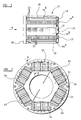
- Figure 1 is a diagrammatic side elevational view of a rotor assembly of a high speed dynamo electric machine with parts thereof omitted for clarity,
- Figure 2 is a view in the direction of arrow "A" in Figure 1 to an increased scale,
- Figure 3 is an enlarged sectional view of part of Figure 2,
- Figure 4 is a cross-sectional view on the line Z - Z in Figure 2,
- Figure 5 is an end elevational view of a spacer of the rotor assembly of Figures 1 and 2,
- Figure 6 is an end elevational view of a closure member of the rotor assembly of Figures 1 and 2,
- Figure 7 is a transverse cross-sectional view of the closure member of Figure 6,
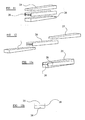
- Figure 8 is a plan view of a locking wedge of the rotor assembly,
- Figure 9 is a side elevational view of a pair of locking wedges of the rotor assembly,
- Figure 10 is a plan view of one of the laminae of the rotor assembly,
- Figures 11 and 12 are oppositely exploded perspective views of a modification of the wedge assembly, and,
- Figures 13a and 13b are perspective and end views respectively of the wedge assembly of Figures 11 and 12 in an operative state.
-
- Referring to the drawings, the rotor assembly includes an elongate generally cylindrical body or rotor core which, in use, is mounted on a rotor shaft for rotation therewith about the axis of the rotor shaft within a corresponding stator assembly. The construction of the rotor core is not of particular significance to the present invention, and it will be recognised that the rotor core may be formed from a plurality of laminae if desired. The rotor core described herein is laminated and Figure 10 illustrates one of the laminae, a plurality of which are stacked in face to face alignment and secured together in a conventional manner. The rotor core includes six equiangularly spaced radially extending
integral poles 12 two of which are seen in part in Figure 3 where they are identified by the reference numerals 12a and 12b respectively. Thepoles 12 are of rectangular cross-section and so define between them generally V-shaped rotor slots. - Each pole is encircled by a rotor winding and thus the axially extending regions of adjacent rotor windings occupy opposite sides of the V-shaped rotor slot. The six rotor windings are illustrated in Figure 2 where they are indicated by the
reference numerals windings - At their radially outermost ends the
poles 12 includeintegral pole ends 19 which define the outer circumferential surface of the rotor body, being parts of a cylinder having its axis coincident with the axis of rotation of the rotor body. The shaping of thepole ends 19 extends through the full axial length of thepoles 12 and the pole ends are extended beyond the side walls of their respective poles in a circumferential direction to define laterally extending pole tips 19a, 19b which extend outwardly over the respective rotor windings throughout the whole axial length of the poles, and partially close the respective rotor slot. - The pole tips 19a, 19b do not completely overlie the respective rotor windings, and in order to hold the rotor windings in place against radially outward movement and centrifugal force as the rotor rotates, there is provided, within each rotor slot, a rotor slot closure member 21 (best seen in Figures 3, 6 and 7). Such rotor slot closure members are sometimes referred to in the art as "wedges".
- Each
closure member 21 is elongate, having a length equal to the axial length of thepoles 12 of the rotor. Each closure member is formed from a material of high strength and relatively low weight, for example titanium, and although eachclosure member 21 is of substantially uniform cross-section along the whole of its length it is apparent from Figures 1 and 7 thatrecesses 22 extend into the central portion of the closure member, from the exterior surface thereof, at a plurality of points spaced along the length of the closure member to minimise the weight of the closure member without significantly impairing its strength. The cross-sectional shape of eachclosure member 21 is generally triangular, the base of the triangle being the outermost face of the closure member and the apex of the triangle extending downwardly into a respective slot and being truncated. Each closure member is recessed along its lateral edges to receive the respective pole tips 19a, 19b on opposite sides of the rotor slot spanned by the closure member, and the closure member includes integral lateral outwardly extending flanges 23a, 23b which extend beneath the respective pole tips 19a, 19b and lie between the pole tips and their respective rotor windings, the flanges 23a, 23b being angled accordingly, so as to extend substantially at right angles to the adjacent poles 12a, 12b. The truncated apex of eachclosure member 21 is shaped to define a rectangular cross-section groove extending the full length of the closure member and having a base wall 21a which is, in use, at right angles to a radially extending plane bisecting the respective rotor slot along its length. - Received within the triangular void between the windings in each rotor slot and the underside of the
closure member 21 is aspacer 24 of chevron shaped cross-section (best seen in Figures 3 and 5). Eachspacer 24 is elongate, being equal in length to the length of thepoles 12 of the rotor and is conveniently formed from aluminium. Eachspacer 24 may be a length cut from an aluminium extrusion, and for weight reduction purposes eachspacer 24 has a longitudinally extending throughbore 25. The outer longitudinally extending faces of thespacer 24 are inclined to one another at an angle equal to the angle subtended between the axes ofadjacent poles 12 and the dimensions of eachspacer 24 are such that the spacer is received between windings of a rotor slot with its outer faces engaging the respective windings along their axial length. The apical edge of thespacer 24 is rounded, and lies adjacent the base of the respective slot, the divergent limbs of thespacer 24 extending outwardly in facial contact with the respective windings (13 and 18 in Figure 3), terminating adjacent the underside of therespective closure member 21. Between its respective limbs eachspacer member 24 defines a longitudinally extending channel of rectangular cross-section the base wall 24a of which lies parallel, in use, to the base wall 21a of the channel of the associatedclosure member 21. The walls 24a, 21a are spaced radially of the rotor assembly from one another. - The
closure member 21 and the associatedspacer 24 will be inserted into each rotor slot in an axial direction, firstly sliding thespacer 24 into place and then introducing theclosure member 21. Although the flanges 23a, 23b of theclosure member 21 are a relatively tight fit between the underside of the pole tips 19a, 19b and the windings, there is little danger of damaging the windings by introducing theclosure member 21 axially since the windings are protected by an outer insulating layer formed from an insulating lacquer, an insulating wrapping or both and by overlying insulating spacer strips, which can withstand the insertion of theclosure member 21. - In order to lock each
closure member 21 and its associatedspacer 24 in a respective rotor slot there is provided a locking wedge assembly comprising first and secondelongate wedges wedges - Initially each
wedge poles 12,closure members 21 andspacers 24. Conveniently eachwedge wedges wedges closure member 21 andspacer 24 respectively. Thewedge 25 is introduced from one axial end of the rotor while thewedge 26 is simultaneously introduced from the opposite axial end of the rotor. Furthermore, the wedges are orientated such that their increasing thickness is disposed radially of the rotor assembly. Thewedges - The dimensions of the
respective spacer 24 andclosure member 21 are such that at approximately the point at which the narrowest ends of the wedges protrude from the opposite axial ends of the rotor the action of the tapering wedges sliding over one another will have pushed the base walls 21a and 24a radially apart by an extent such that thespacer 24 firmly engages the windings of its associated slot and the flanges 23a, 23b of the closure member are firmly engaged with the under-surface of their respective pole tips 19a, 19b. Thus at this point there is no free play in a radial direction, but no significant clamping pressure has been generated by thewedges wedges spacer 24 against the respective rotor windings while simultaneously loading the flanges 23a, 23b of the associated closure member against the pole tips 19a, 19b. The loading applied simultaneously to the twowedges spacer 24 against the windings and theclosure member 21 against the pole tips. Conveniently no more than about 445 Newtons (100lbs force) is applied to the ends of thewedges closure member 21 sufficiently to overstress the pole tips 19a, 19b, but these values may not be appropriate in all applications and the actual values can easily be determined by the skilled man. - The locking force applied by the
wedges spacer 24, theclosure member 21, and the windings 13-18 rigidly in place, sufficiently tightly to accommodate vibration, and centrifugal force even at the high rotational speeds to which the rotor will be subjected in use. - After the
wedges respective closure member 21 and spacer 24 (see Figure 4). Thereafter an end band in the form of ametal annulus 26 is attached to each axial end of the rotor assembly to overlie the trimmed ends of thewedges end band 26 is shown in Figure 1, the other end band having been omitted for clarity. As is apparent from Figure 4, theend bands 26 are secured in position by cap screws extending through the end bands and threaded into the end regions of theclosure members 21. Trimming the wedges to leave a small protrusion at both ends of the rotor core facilitates extraction of the wedges for servicing/repair of the rotor assembly if necessary. It is to be understood however that the wedges could be trimmed substantially flush with the ends of the rotor core if desired. - It will be recognised that as the locking
wedges wedges respective spacer 24 andclosure member 21, provides a radial expansion in a uniform manner applied simultaneously along the whole length of eachspacer 24 and associatedclosure member 21. The expansion force provided by the co-action of the two wedges is thus not applied at discrete locations, but is applied simultaneously and uniformly along the whole length of the rotor assembly. It follows therefore that the loading applied by thespacer 24 to the windings and theclosure member 21 to the pole tips is also applied uniformly, and simultaneously along the whole axial length of the rotor. There is little risk of damage to the winding insulation during the radial expansion of the lockingwedge assembly spacer 24 relative to the windings during this process is negligible. - Carbon fibre composite has been identified as the material of choice for the
wedges - The combination of
closure member 21,spacer 24, andwedges - Desirably, the
wedges wedge assembly - In the modification shown in Figures 11, 12 and 13, the locking wedge assembly further comprises an
alignment member 28. Thealignment member 28 is elongate, corresponding in length to the axial length of thepoles 12 of the rotor. Themember 28 is of 'I'-shaped cross-section, thus providing two oppositely facing elongate channels in which the twowedges wedges alignment member 28. When the wedges are orientated, one on either side of thealignment member 28, such that the thickest end of one wedge is located adjacent to the thinnest end of the other wedge, the uniform radial expansion of the wedge assembly as described above is preserved, as shown in Figures 13a and 13b. - In use, the
alignment member 28 is inserted into the gap between the walls 21a, 24a of the associatedclosure member 21 andspacer 24 respectively fitting into the channels formed in themember 21 andspacer 24, before insertion of the narrow ends of thewedges member 28. - The
member 28 is of particular benefit in rotor assemblies where themembers 21 andspacers 24 are not formed with channels the bases of which define the walls 21a and 24a, since it will fit in the gap between therespective member 21 and its associatedspacer 24, and will provide its own channels guiding the longitudinal movement of thewedges - Moreover the provision of
members 28 is similarly beneficial in rotor assemblies where the channels in themembers 21 andspacers 24 are too wide relative to theirrespective wedges member 28 will restrain itsrespective wedges wedges wedges alignment member 28. It will be recognised that whereas without themember 28 the wedges are in physical sliding contact with one another, where themember 28 is provided a common base wall of the channels of themember 28 spaces thewedges
Claims (12)
- A rotor assembly for a dynamo electric machine, the rotor assembly comprising a rotor core incorporating radially extending rotor poles (12), rotor windings (13-18) encircling respective rotor poles, circumferentially extending pole tips (19a, 19b) at the outer end of each pole respectively, said tips overlying the rotor winding encircling the respective pole, a plurality of rotor slot closure members (21), each closure member spanning the gap between a pair of adjacent poles, and including lateral flanges (23a, 23b) interposed between the respective rotor windings and the associated pole tips, and a spacer member (24) positioned beneath each closure member and engaging the radially extending faces of the adjacent windings, the rotor assembly being characterised by a locking wedge assembly comprising a pair of tapering locking wedges (25, 26) extending axially of the rotor assembly between each closure member (21) and the associated spacer (24), the locking wedges (25, 26) extending with their tapers in opposite directions so that moving the wedges longitudinally towards one another increases the radial dimension of the combination of the locking wedges driving the associated spacer and closure apart in a radial direction.
- A rotor assembly as claimed in claim 1 characterised in that the locking wedges (25, 26) are each received in an elongate channel formed in the respective closure member (21) and spacer (24).
- A rotor assembly as claimed in claim 1 characterised in that the locking wedges are each received in respective elongate oppositely facing channels formed in a respective elongate alignment member (28) interposed between the respective closure member (21) and spacer (24), and are in sliding relationship with one another through contact with a dividing wall of the alignment member.
- A rotor assembly as claimed in any one of claims 1 to 3 characterised in that said closure members and said spacers are equal in length to the axial length of the poles of the rotor core, and said first and second locking wedges are initially of a length exceeding the axial length of the poles.
- A rotor assembly as claimed in any one of claims 1 to 4 characterised in that the first and second wedges are formed from a carbon fibre composite material.
- A rotor assembly as claimed in any one of claims 1 to 5 characterised in that the first and second wedges each have a 2° taper over their whole length.
- A rotor assembly as claimed in any one of claims 1 to 6 characterised in that a single wedge shaped blank is cut to produce substantially identical first and second wedges.
- A method of manufacturing a rotor assembly for a dynamo electric machine comprising, starting with a rotor core including a plurality of circumferentially spaced radially extending poles (12) encircled by respective rotor windings (13-18), a respective spacer (24) received in the gap between the windings of each circumferentially adjacent pair of windings, a respective closure member (21) circumferentially spanning the gap between the poles of each adjacent pair of poles, each closure member including lateral flanges received between a respective winding and the underside of a respective circumferentially extending pole tip, and the method being characterised by including introducing a respective locking wedge assembly between each spacer and its associated closure, each locking wedge assembly comprising first and second elongate tapering wedges (25, 26) with their tapers extending in opposite directions axially of the rotor assembly, said first and second wedges having their taper arranged radially of the rotor assembly, the first wedge having a face in contact with the respective closure member (21), the second wedge having a face in contact with the respective spacer (24), and the two wedges having their opposite face in sliding contact, and, driving the wedges axially of the rotor assembly to move their wider ends towards the transverse median plane of the rotor assembly so as to urge the respective closure member and the respective spacer radially apart.
- A method as claimed in claim 8 characterised in that the locking wedges are each received in respective elongate oppositely facing channels formed in a respective elongate alignment member (28) interposed between the respective closure member and spacer, and are in sliding relationship by way of a dividing wall of the alignment member (28).
- A method as claimed in claim 8 or claim 9 characterised in that said closure members and said spacers are equal in length to the axial length of the poles of the rotor core, and said first and second locking wedges are initially of a length exceeding the axial length of the poles, the dimensions of the wedges, the closure members and the spacers being such that the first and second wedges are inserted substantially completely through the axial length of the rotor before significant radial force is applied to the respective spacer and closure member, the wedges then being pressed further to load the respective spacer and the respective closure member radially apart and subsequently trimming the protruding regions of the first and second wedges, at both axial ends of the rotor assembly, to be substantially flush with the axial ends of the spacers and closure members.
- A method as claimed in any one of claims 8 to 10 characterised in that a wedge insertion apparatus applies a predetermined force simultaneously to the wider ends of the first and second wedges of each wedge assembly to drive the wider ends of the first and second wedges towards one another, the predetermined force applied simultaneously to both wedges being calculated to move the wedges to a position in which a predetermined desired radial loading is applied to the respective spacer and closure member.
- A method as claimed in any one of claims 8 to 11 characterised in that a single wedge shaped blank is cut to produce substantially identical first and second wedges.
Applications Claiming Priority (2)
| Application Number | Priority Date | Filing Date | Title |
|---|---|---|---|
| GB0314636 | 2003-06-24 | ||
| GBGB0314636.2A GB0314636D0 (en) | 2003-06-24 | 2003-06-24 | Dynamo electric machines |
Publications (2)
| Publication Number | Publication Date |
|---|---|
| EP1494335A1 true EP1494335A1 (en) | 2005-01-05 |
| EP1494335B1 EP1494335B1 (en) | 2007-04-04 |
Family
ID=27637186
Family Applications (1)
| Application Number | Title | Priority Date | Filing Date |
|---|---|---|---|
| EP04253730A Expired - Lifetime EP1494335B1 (en) | 2003-06-24 | 2004-06-22 | Rotor assembly for dynamo electric machines |
Country Status (5)
| Country | Link |
|---|---|
| US (1) | US6933648B2 (en) |
| EP (1) | EP1494335B1 (en) |
| DE (1) | DE602004005631T2 (en) |
| ES (1) | ES2285364T3 (en) |
| GB (1) | GB0314636D0 (en) |
Cited By (7)
| Publication number | Priority date | Publication date | Assignee | Title |
|---|---|---|---|---|
| EP2296256A2 (en) | 2009-09-10 | 2011-03-16 | Goodrich Control Systems Ltd | Rotor assembly |
| WO2013110580A1 (en) * | 2012-01-26 | 2013-08-01 | Continental Automotive Gmbh | Rotor for a rotating electrical machine and electric motor |
| CN103532269A (en) * | 2013-10-11 | 2014-01-22 | 陕西航空电气有限责任公司 | Aviation high-speed generator rotor structure |
| GB2505909A (en) * | 2012-09-13 | 2014-03-19 | Nidec Sr Drives Ltd | Salient pole stator coil retainer with coolant passage |
| WO2014037776A3 (en) * | 2012-09-06 | 2015-03-05 | Toyota Jidosha Kabushiki Kaisha | Rotor for rotating electrical device |
| FR3079978A1 (en) * | 2018-04-04 | 2019-10-11 | Renault S.A.S | ROTOR CROWN FOR ROTOR OF ELECTRIC MACHINE AND ROTOR COMPRISING SUCH A CROWN |
| WO2022012841A1 (en) * | 2020-07-17 | 2022-01-20 | Vitesco Technologies GmbH | Rotor for a rotating electric machine, electric machine |
Families Citing this family (34)
| Publication number | Priority date | Publication date | Assignee | Title |
|---|---|---|---|---|
| US6791230B2 (en) * | 2001-09-07 | 2004-09-14 | Honeywell International, Inc. | System and method for retaining wedges in a rotor |
| US7015616B2 (en) * | 2002-04-01 | 2006-03-21 | Honeywell International, Inc. | System and method for providing coil retention in the rotor windings of a high speed generator |
| US6984910B2 (en) * | 2003-01-13 | 2006-01-10 | Honeywell International, Inc. | Generator with composite rotor coil retention components |
| GB0702997D0 (en) * | 2007-02-16 | 2007-03-28 | Rolls Royce Plc | A cooling arrangement of an electrical machine |
| US7936103B2 (en) * | 2007-11-21 | 2011-05-03 | General Electric Company | Methods for fabricating a wedge system for an electric machine |
| US7821171B2 (en) * | 2008-12-02 | 2010-10-26 | Hamilton Sundstrand Corporation | Generator wedge with reduced eddy current losses |
| US7816836B2 (en) * | 2009-01-30 | 2010-10-19 | Honeywell International Inc. | Reduced stress generator pole tip fillet |
| US8232702B2 (en) * | 2010-07-30 | 2012-07-31 | Ge Aviation Systems, Llc | Apparatus for a high speed sleeveless rotor |
| EP2434617A1 (en) * | 2010-09-24 | 2012-03-28 | Siemens Aktiengesellschaft | Generator for an electrical machine |
| US8179028B1 (en) * | 2011-08-08 | 2012-05-15 | Rao Dantam K | Prevention of core failures in large electric machines |
| US9634526B2 (en) | 2012-01-26 | 2017-04-25 | Continental Automotive Gmbh | Rotor for a rotating electric machine and rotating electric machine |
| US9735642B2 (en) | 2012-01-26 | 2017-08-15 | Continental Automotive Gmbh | Rotor for a rotating electric machine |
| US8853911B2 (en) * | 2012-09-28 | 2014-10-07 | Hamilton Sundstrand Corporation | Generator/motor wedge with lamination interface for reduced stress levels |
| WO2015034514A1 (en) | 2013-09-06 | 2015-03-12 | Ge Aviation Systems Llc | Rotor assembly for an electric machine |
| KR20150128486A (en) * | 2014-05-09 | 2015-11-18 | 주식회사 만도 | Rotor for Wound-Rotor Induction Motor Having Anti-Spattering Member |
| KR101637676B1 (en) | 2014-09-05 | 2016-07-07 | 현대자동차주식회사 | Armature of rotating electric machine with improved wedges |
| US10063116B2 (en) * | 2014-10-07 | 2018-08-28 | Hamilton Sundstrand Corporation | Lamination clamping structure |
| US9866085B2 (en) | 2014-10-13 | 2018-01-09 | Hamilton Sundstrand Corporation | Generator motor wedge with wide arm span and reduced stress levels |
| US9653958B2 (en) * | 2015-01-16 | 2017-05-16 | Hamilton Sundstrand Corporation | Rotor wedge with arms |
| KR101745127B1 (en) | 2015-08-26 | 2017-06-08 | 현대자동차주식회사 | Armature of rotating electric machine |
| US20170358968A1 (en) * | 2016-06-13 | 2017-12-14 | Alstom Renewable Technologies | Supporting device and method for supporting winding coils in a wind turbine generator |
| US10541580B2 (en) * | 2017-03-27 | 2020-01-21 | Hamilton Sundstrand Corporation | Wedges with Q-axis damper circuits |
| US11081920B2 (en) * | 2017-09-29 | 2021-08-03 | Hamilton Sundstrand Corporation | Rotor wedges and layers and heat sinks |
| FR3081630B1 (en) * | 2018-05-22 | 2020-11-20 | Renault Sas | CAGE FOR ROTOR OF SYNCHRONOUS ELECTRIC MACHINE. |
| FR3087589B1 (en) * | 2018-10-19 | 2023-11-03 | Leroy Somer Moteurs | ELECTRIC ROTATING MACHINE |
| DE102018130475A1 (en) * | 2018-11-30 | 2020-06-04 | Valeo Siemens Eautomotive Germany Gmbh | Rotor with a winding for an electrical machine |
| DE102020110664A1 (en) | 2020-04-20 | 2021-10-21 | Audi Aktiengesellschaft | Electric machine and motor vehicle |
| DE102020119679A1 (en) | 2020-07-27 | 2022-01-27 | Audi Aktiengesellschaft | Electric machine and motor vehicle |
| US11569703B2 (en) | 2021-01-04 | 2023-01-31 | Hamilton Sundstrand Corporation | Integrated wedge cooling distribution plate and end turn support |
| US11539273B2 (en) | 2021-01-05 | 2022-12-27 | Hamilton Sundstrand Corporation | Composites and methods of making composite materials |
| CN113446917B (en) * | 2021-08-10 | 2022-08-26 | 哈尔滨电气动力装备有限公司 | Rotor core slot width measuring tool |
| DE102022124453A1 (en) | 2022-06-29 | 2024-01-04 | Schaeffler Technologies AG & Co. KG | Cooled slot body for a wound rotor |
| WO2024170041A1 (en) | 2023-02-17 | 2024-08-22 | Schaeffler Technologies AG & Co. KG | Rotor arrangement and electric machine |
| DE102023105537B4 (en) | 2023-03-07 | 2024-09-19 | Schaeffler Technologies AG & Co. KG | Rotor arrangement |
Citations (4)
| Publication number | Priority date | Publication date | Assignee | Title |
|---|---|---|---|---|
| DE2007735A1 (en) * | 1969-02-21 | 1970-09-03 | Rotax Ltd., Birmingham, Warwickshire (Grossbritannien) | Cooling device for dynamo-electric machines |
| EP1005135A1 (en) * | 1998-11-03 | 2000-05-31 | Lucas Industries Limited | Electric machine and rotor for use therein |
| US6113024A (en) * | 1999-04-30 | 2000-09-05 | Alliedsignal Inc. | Winding wedge retention to maintain coil form |
| US6313561B1 (en) * | 2000-01-26 | 2001-11-06 | General Electric Company | Dynamic blocking restraint of a rotor field winding contained by a non-metallic structural rotor enclosure |
Family Cites Families (2)
| Publication number | Priority date | Publication date | Assignee | Title |
|---|---|---|---|---|
| US3008786A (en) * | 1958-07-24 | 1961-11-14 | Gen Electric | Dynamoelectric machine construction |
| US5140204A (en) * | 1991-07-05 | 1992-08-18 | Westinghouse Electric Corp. | Heat pipes for cooling pole windings of salient pole machines |
-
2003
- 2003-06-24 GB GBGB0314636.2A patent/GB0314636D0/en not_active Ceased
-
2004
- 2004-06-22 EP EP04253730A patent/EP1494335B1/en not_active Expired - Lifetime
- 2004-06-22 ES ES04253730T patent/ES2285364T3/en not_active Expired - Lifetime
- 2004-06-22 DE DE602004005631T patent/DE602004005631T2/en not_active Expired - Lifetime
- 2004-06-24 US US10/876,253 patent/US6933648B2/en not_active Expired - Lifetime
Patent Citations (4)
| Publication number | Priority date | Publication date | Assignee | Title |
|---|---|---|---|---|
| DE2007735A1 (en) * | 1969-02-21 | 1970-09-03 | Rotax Ltd., Birmingham, Warwickshire (Grossbritannien) | Cooling device for dynamo-electric machines |
| EP1005135A1 (en) * | 1998-11-03 | 2000-05-31 | Lucas Industries Limited | Electric machine and rotor for use therein |
| US6113024A (en) * | 1999-04-30 | 2000-09-05 | Alliedsignal Inc. | Winding wedge retention to maintain coil form |
| US6313561B1 (en) * | 2000-01-26 | 2001-11-06 | General Electric Company | Dynamic blocking restraint of a rotor field winding contained by a non-metallic structural rotor enclosure |
Cited By (9)
| Publication number | Priority date | Publication date | Assignee | Title |
|---|---|---|---|---|
| EP2296256A2 (en) | 2009-09-10 | 2011-03-16 | Goodrich Control Systems Ltd | Rotor assembly |
| EP2296256A3 (en) * | 2009-09-10 | 2012-08-22 | Goodrich Control Systems Ltd | Rotor assembly |
| WO2013110580A1 (en) * | 2012-01-26 | 2013-08-01 | Continental Automotive Gmbh | Rotor for a rotating electrical machine and electric motor |
| WO2014037776A3 (en) * | 2012-09-06 | 2015-03-05 | Toyota Jidosha Kabushiki Kaisha | Rotor for rotating electrical device |
| CN104471837B (en) * | 2012-09-06 | 2017-05-10 | 丰田自动车株式会社 | Rotor for rotating electrical device |
| GB2505909A (en) * | 2012-09-13 | 2014-03-19 | Nidec Sr Drives Ltd | Salient pole stator coil retainer with coolant passage |
| CN103532269A (en) * | 2013-10-11 | 2014-01-22 | 陕西航空电气有限责任公司 | Aviation high-speed generator rotor structure |
| FR3079978A1 (en) * | 2018-04-04 | 2019-10-11 | Renault S.A.S | ROTOR CROWN FOR ROTOR OF ELECTRIC MACHINE AND ROTOR COMPRISING SUCH A CROWN |
| WO2022012841A1 (en) * | 2020-07-17 | 2022-01-20 | Vitesco Technologies GmbH | Rotor for a rotating electric machine, electric machine |
Also Published As
| Publication number | Publication date |
|---|---|
| US6933648B2 (en) | 2005-08-23 |
| DE602004005631D1 (en) | 2007-05-16 |
| DE602004005631T2 (en) | 2007-12-13 |
| ES2285364T3 (en) | 2007-11-16 |
| US20040263019A1 (en) | 2004-12-30 |
| GB0314636D0 (en) | 2003-07-30 |
| EP1494335B1 (en) | 2007-04-04 |
Similar Documents
| Publication | Publication Date | Title |
|---|---|---|
| EP1494335B1 (en) | Rotor assembly for dynamo electric machines | |
| EP2409382B1 (en) | Electric device rotor and methods for manufacture | |
| EP2840692B1 (en) | Spoke permanent magnet machine with reduced torque ripple and method of manufacturing thereof | |
| EP1813010B1 (en) | Design of the magnet and webs in interior permanent magent rotors | |
| US8018114B2 (en) | Generator rotor with improved wedges | |
| US7015616B2 (en) | System and method for providing coil retention in the rotor windings of a high speed generator | |
| EP1542335B1 (en) | Rotor for rotary electric machine | |
| JP2021526002A (en) | Stator for rotating electromechanical | |
| US4363986A (en) | Rotor of an electrical machine | |
| US20210218294A1 (en) | Stator for a rotating electrical machine | |
| CN112823464A (en) | Rotor for an electric motor, method for producing a rotor, and electric motor | |
| JP2021526001A (en) | Stator for rotating electromechanical | |
| US4179635A (en) | Device for bracing a stator winding disposed in the air gap of a synchronous generator | |
| CN110544996B (en) | Rotor for reluctance motor, manufacturing method, reluctance motor and motor vehicle | |
| US11962187B2 (en) | Stator for a rotating electrical machine | |
| EP1339157B1 (en) | Rotor comprising slots for wedges | |
| US20110215669A1 (en) | Rotor Assembly | |
| KR101598381B1 (en) | Rotating electric machine, in particular double-fed asynchronous machine in the performance range between 20 mva and more than 500 mva | |
| US6703733B1 (en) | Removable self-locking field winding block | |
| US6208059B1 (en) | Rotor for an electric machine, retainer for retaining a winding in a slot in a rotor, and method of manufacturing a rotor | |
| WO2022176829A1 (en) | Rotor | |
| EP1054497A2 (en) | Method of manufacturing a component for a rotating machine, and a rotor including such components |
Legal Events
| Date | Code | Title | Description |
|---|---|---|---|
| PUAI | Public reference made under article 153(3) epc to a published international application that has entered the european phase |
Free format text: ORIGINAL CODE: 0009012 |
|
| AK | Designated contracting states |
Kind code of ref document: A1 Designated state(s): AT BE BG CH CY CZ DE DK EE ES FI FR GB GR HU IE IT LI LU MC NL PL PT RO SE SI SK TR |
|
| AX | Request for extension of the european patent |
Extension state: AL HR LT LV MK |
|
| 17P | Request for examination filed |
Effective date: 20050609 |
|
| AKX | Designation fees paid |
Designated state(s): DE ES FR GB IT |
|
| GRAP | Despatch of communication of intention to grant a patent |
Free format text: ORIGINAL CODE: EPIDOSNIGR1 |
|
| GRAS | Grant fee paid |
Free format text: ORIGINAL CODE: EPIDOSNIGR3 |
|
| GRAA | (expected) grant |
Free format text: ORIGINAL CODE: 0009210 |
|
| AK | Designated contracting states |
Kind code of ref document: B1 Designated state(s): DE ES FR GB IT |
|
| REG | Reference to a national code |
Ref country code: GB Ref legal event code: FG4D |
|
| REF | Corresponds to: |
Ref document number: 602004005631 Country of ref document: DE Date of ref document: 20070516 Kind code of ref document: P |
|
| ET | Fr: translation filed | ||
| REG | Reference to a national code |
Ref country code: ES Ref legal event code: FG2A Ref document number: 2285364 Country of ref document: ES Kind code of ref document: T3 |
|
| PLBE | No opposition filed within time limit |
Free format text: ORIGINAL CODE: 0009261 |
|
| STAA | Information on the status of an ep patent application or granted ep patent |
Free format text: STATUS: NO OPPOSITION FILED WITHIN TIME LIMIT |
|
| 26N | No opposition filed |
Effective date: 20080107 |
|
| PG25 | Lapsed in a contracting state [announced via postgrant information from national office to epo] |
Ref country code: IT Free format text: LAPSE BECAUSE OF FAILURE TO SUBMIT A TRANSLATION OF THE DESCRIPTION OR TO PAY THE FEE WITHIN THE PRESCRIBED TIME-LIMIT Effective date: 20070404 |
|
| PGFP | Annual fee paid to national office [announced via postgrant information from national office to epo] |
Ref country code: ES Payment date: 20090709 Year of fee payment: 6 |
|
| REG | Reference to a national code |
Ref country code: ES Ref legal event code: FD2A Effective date: 20110715 |
|
| PG25 | Lapsed in a contracting state [announced via postgrant information from national office to epo] |
Ref country code: ES Free format text: LAPSE BECAUSE OF NON-PAYMENT OF DUE FEES Effective date: 20110705 |
|
| PG25 | Lapsed in a contracting state [announced via postgrant information from national office to epo] |
Ref country code: ES Free format text: LAPSE BECAUSE OF NON-PAYMENT OF DUE FEES Effective date: 20100623 |
|
| REG | Reference to a national code |
Ref country code: DE Ref legal event code: R081 Ref document number: 602004005631 Country of ref document: DE Owner name: GOODRICH CONTROL SYSTEMS, GB Free format text: FORMER OWNER: GOODRICH CONTROL SYSTEMS LTD., SOLIHULL, GB Effective date: 20130219 Ref country code: DE Ref legal event code: R081 Ref document number: 602004005631 Country of ref document: DE Owner name: SAFRAN POWER UK LTD., GB Free format text: FORMER OWNER: GOODRICH CONTROL SYSTEMS LTD., SOLIHULL, GB Effective date: 20130219 Ref country code: DE Ref legal event code: R081 Ref document number: 602004005631 Country of ref document: DE Owner name: SAFRAN POWER UK LTD., PITSTONE GREEN, GB Free format text: FORMER OWNER: GOODRICH CONTROL SYSTEMS LTD., SOLIHULL, WEST MIDLANDS, GB Effective date: 20130219 |
|
| REG | Reference to a national code |
Ref country code: FR Ref legal event code: CJ Effective date: 20130617 Ref country code: FR Ref legal event code: CD Owner name: GOODRICH CONTROL SYSTEMS Effective date: 20130617 |
|
| REG | Reference to a national code |
Ref country code: DE Ref legal event code: R081 Ref document number: 602004005631 Country of ref document: DE Owner name: SAFRAN POWER UK LTD., GB Free format text: FORMER OWNER: GOODRICH CONTROL SYSTEMS, SOLIHULL, GB Effective date: 20131024 Ref country code: DE Ref legal event code: R082 Ref document number: 602004005631 Country of ref document: DE Representative=s name: CABINET REGIMBEAU, FR Effective date: 20131024 Ref country code: DE Ref legal event code: R081 Ref document number: 602004005631 Country of ref document: DE Owner name: SAFRAN POWER UK LTD., PITSTONE GREEN, GB Free format text: FORMER OWNER: GOODRICH CONTROL SYSTEMS, SOLIHULL, WEST MIDLANDS, GB Effective date: 20131024 Ref country code: DE Ref legal event code: R082 Ref document number: 602004005631 Country of ref document: DE Representative=s name: REGIMBEAU, FR Effective date: 20131024 |
|
| REG | Reference to a national code |
Ref country code: GB Ref legal event code: 732E Free format text: REGISTERED BETWEEN 20140522 AND 20140528 |
|
| REG | Reference to a national code |
Ref country code: FR Ref legal event code: PLFP Year of fee payment: 13 |
|
| REG | Reference to a national code |
Ref country code: FR Ref legal event code: PLFP Year of fee payment: 14 |
|
| REG | Reference to a national code |
Ref country code: FR Ref legal event code: PLFP Year of fee payment: 15 |
|
| PGFP | Annual fee paid to national office [announced via postgrant information from national office to epo] |
Ref country code: DE Payment date: 20210519 Year of fee payment: 18 |
|
| REG | Reference to a national code |
Ref country code: DE Ref legal event code: R119 Ref document number: 602004005631 Country of ref document: DE |
|
| PG25 | Lapsed in a contracting state [announced via postgrant information from national office to epo] |
Ref country code: DE Free format text: LAPSE BECAUSE OF NON-PAYMENT OF DUE FEES Effective date: 20230103 |
|
| PGFP | Annual fee paid to national office [announced via postgrant information from national office to epo] |
Ref country code: FR Payment date: 20230524 Year of fee payment: 20 |
|
| PGFP | Annual fee paid to national office [announced via postgrant information from national office to epo] |
Ref country code: GB Payment date: 20230523 Year of fee payment: 20 |
|
| PG25 | Lapsed in a contracting state [announced via postgrant information from national office to epo] |
Ref country code: GB Free format text: LAPSE BECAUSE OF EXPIRATION OF PROTECTION Effective date: 20240621 |
|
| REG | Reference to a national code |
Ref country code: GB Ref legal event code: PE20 Expiry date: 20240621 |
|
| PG25 | Lapsed in a contracting state [announced via postgrant information from national office to epo] |
Ref country code: GB Free format text: LAPSE BECAUSE OF EXPIRATION OF PROTECTION Effective date: 20240621 |