EP1494321B1 - Zipper connector - Google Patents
Zipper connector Download PDFInfo
- Publication number
- EP1494321B1 EP1494321B1 EP04022095A EP04022095A EP1494321B1 EP 1494321 B1 EP1494321 B1 EP 1494321B1 EP 04022095 A EP04022095 A EP 04022095A EP 04022095 A EP04022095 A EP 04022095A EP 1494321 B1 EP1494321 B1 EP 1494321B1
- Authority
- EP
- European Patent Office
- Prior art keywords
- teeth
- conductor
- zipper
- support
- circuit part
- Prior art date
- Legal status (The legal status is an assumption and is not a legal conclusion. Google has not performed a legal analysis and makes no representation as to the accuracy of the status listed.)
- Expired - Fee Related
Links
Images

Classifications
-
- H—ELECTRICITY
- H01—ELECTRIC ELEMENTS
- H01R—ELECTRICALLY-CONDUCTIVE CONNECTIONS; STRUCTURAL ASSOCIATIONS OF A PLURALITY OF MUTUALLY-INSULATED ELECTRICAL CONNECTING ELEMENTS; COUPLING DEVICES; CURRENT COLLECTORS
- H01R12/00—Structural associations of a plurality of mutually-insulated electrical connecting elements, specially adapted for printed circuits, e.g. printed circuit boards [PCB], flat or ribbon cables, or like generally planar structures, e.g. terminal strips, terminal blocks; Coupling devices specially adapted for printed circuits, flat or ribbon cables, or like generally planar structures; Terminals specially adapted for contact with, or insertion into, printed circuits, flat or ribbon cables, or like generally planar structures
- H01R12/70—Coupling devices
- H01R12/77—Coupling devices for flexible printed circuits, flat or ribbon cables or like structures
- H01R12/771—Details
- H01R12/774—Retainers
-
- H—ELECTRICITY
- H01—ELECTRIC ELEMENTS
- H01R—ELECTRICALLY-CONDUCTIVE CONNECTIONS; STRUCTURAL ASSOCIATIONS OF A PLURALITY OF MUTUALLY-INSULATED ELECTRICAL CONNECTING ELEMENTS; COUPLING DEVICES; CURRENT COLLECTORS
- H01R12/00—Structural associations of a plurality of mutually-insulated electrical connecting elements, specially adapted for printed circuits, e.g. printed circuit boards [PCB], flat or ribbon cables, or like generally planar structures, e.g. terminal strips, terminal blocks; Coupling devices specially adapted for printed circuits, flat or ribbon cables, or like generally planar structures; Terminals specially adapted for contact with, or insertion into, printed circuits, flat or ribbon cables, or like generally planar structures
- H01R12/70—Coupling devices
- H01R12/77—Coupling devices for flexible printed circuits, flat or ribbon cables or like structures
- H01R12/78—Coupling devices for flexible printed circuits, flat or ribbon cables or like structures connecting to other flexible printed circuits, flat or ribbon cables or like structures
-
- H—ELECTRICITY
- H01—ELECTRIC ELEMENTS
- H01R—ELECTRICALLY-CONDUCTIVE CONNECTIONS; STRUCTURAL ASSOCIATIONS OF A PLURALITY OF MUTUALLY-INSULATED ELECTRICAL CONNECTING ELEMENTS; COUPLING DEVICES; CURRENT COLLECTORS
- H01R12/00—Structural associations of a plurality of mutually-insulated electrical connecting elements, specially adapted for printed circuits, e.g. printed circuit boards [PCB], flat or ribbon cables, or like generally planar structures, e.g. terminal strips, terminal blocks; Coupling devices specially adapted for printed circuits, flat or ribbon cables, or like generally planar structures; Terminals specially adapted for contact with, or insertion into, printed circuits, flat or ribbon cables, or like generally planar structures
- H01R12/70—Coupling devices
- H01R12/82—Coupling devices connected with low or zero insertion force
- H01R12/85—Coupling devices connected with low or zero insertion force contact pressure producing means, contacts activated after insertion of printed circuits or like structures
- H01R12/89—Coupling devices connected with low or zero insertion force contact pressure producing means, contacts activated after insertion of printed circuits or like structures acting manually by moving connector housing parts linearly, e.g. slider
-
- H—ELECTRICITY
- H01—ELECTRIC ELEMENTS
- H01R—ELECTRICALLY-CONDUCTIVE CONNECTIONS; STRUCTURAL ASSOCIATIONS OF A PLURALITY OF MUTUALLY-INSULATED ELECTRICAL CONNECTING ELEMENTS; COUPLING DEVICES; CURRENT COLLECTORS
- H01R13/00—Details of coupling devices of the kinds covered by groups H01R12/70 or H01R24/00 - H01R33/00
- H01R13/02—Contact members
- H01R13/20—Pins, blades, or sockets shaped, or provided with separate member, to retain co-operating parts together
-
- H—ELECTRICITY
- H01—ELECTRIC ELEMENTS
- H01R—ELECTRICALLY-CONDUCTIVE CONNECTIONS; STRUCTURAL ASSOCIATIONS OF A PLURALITY OF MUTUALLY-INSULATED ELECTRICAL CONNECTING ELEMENTS; COUPLING DEVICES; CURRENT COLLECTORS
- H01R13/00—Details of coupling devices of the kinds covered by groups H01R12/70 or H01R24/00 - H01R33/00
- H01R13/02—Contact members
- H01R13/28—Contacts for sliding cooperation with identically-shaped contact, e.g. for hermaphroditic coupling devices
-
- H—ELECTRICITY
- H05—ELECTRIC TECHNIQUES NOT OTHERWISE PROVIDED FOR
- H05K—PRINTED CIRCUITS; CASINGS OR CONSTRUCTIONAL DETAILS OF ELECTRIC APPARATUS; MANUFACTURE OF ASSEMBLAGES OF ELECTRICAL COMPONENTS
- H05K3/00—Apparatus or processes for manufacturing printed circuits
- H05K3/30—Assembling printed circuits with electric components, e.g. with resistor
- H05K3/32—Assembling printed circuits with electric components, e.g. with resistor electrically connecting electric components or wires to printed circuits
- H05K3/325—Assembling printed circuits with electric components, e.g. with resistor electrically connecting electric components or wires to printed circuits by abutting or pinching, i.e. without alloying process; mechanical auxiliary parts therefor
- H05K3/326—Assembling printed circuits with electric components, e.g. with resistor electrically connecting electric components or wires to printed circuits by abutting or pinching, i.e. without alloying process; mechanical auxiliary parts therefor the printed circuit having integral resilient or deformable parts, e.g. tabs or parts of flexible circuits
Definitions
- the present invention relates to a circuit part for a connector for connecting a plurality of first contacts on a first support to a plurality of second contacts on a second support.
- US-A-4931021 relates to a system for connecting and disconnecting substantially planar arrays of electrical contact sites in a mechanically secure and functionally rapid and reversible manner.
- the system utilizes technology available in the zipper manufacturing industry, to achieve a high contact site density by suitably disposing contact sites for electrical connections on zipper teeth, and through the use of a conventional zipper-type runner achieving the interconnection of a multiplicity of electrical contact sites.
- the present invention provides a circuit part comprising:
- the present invention is based on the finding that the zipper technique, well-known from a plurality of fields of application, closing for example, can be utilized to provide connection between a plurality of contacts or pins of circuit parts such as printed circuit boards, flexible printed circuit boards and ribbon cables.
- the contacts or pins are designed as conductor teeth or contact teeth which can have the shape of traditional zipper teeth.
- a conventional zipper slider can be used for closing the zipper, i.e. causing the mechanical and electrical connections between the teeth on the first and second support.
- the conductor teeth i.e. the contact teeth
- the conductor teeth are separated by electrically insulating teeth, for example plastic teeth, such that, electrically insulated from each other, a plurality of electrical connections between conductor teeth can be achieved.
- the conductor teeth and the insulating teeth are provided with a spring mechanism in order to improve the electrical contact between adjacent teeth when connected.
- the present invention provides a new type of a connector by which a plurality of pins in the form of conductor teeth can be connected and disconnected with reduced force when compared to traditional connectors.
- large connection/disconnection forces occurring in traditional kinds of connectors having a large number of pins (for example more than 100), which can cause a damage to the connector or the device having the connector do not occur according to the invention.
- the connector according to the invention is elastic.
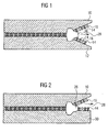
- Fig. 1 shows an embodiment of the present invention in which two ribbon cables 10 and 12 are connected via the inventive connector arrangement.
- a plurality of conductor teeth 14 (indicated by hatching) and insulating teeth 16 are arranged along an edge of the ribbon cable 10 so as to protrude therefrom.
- a plurality of conductor teeth 14 and insulating teeth 16 are provided along an edge of the ribbon cable 12.
- the respective conductor teeth 14 are electrically connected to respective conductors or conductive regions of the ribbon cables 10 and 12 as it is indicated in Fig. 3 by conductors 18.
- each tooth comprises an extended top portion 20, a narrowed middle portion 22 and an extended lower portion 24.
- the teeth of the upper part thereof and the teeth of the lower part thereof are arranged dislocated with respect to each other so that the extended portions 20 of the upper part teeth can be placed into the space formed by the narrowed portions 22 of adjacent lower part teeth.
- a zipper slider or zipper clasp 26 ( Fig. 1 ) is used.
- the zipper slider acts like a conventional zipper slider in order to close the zipper when moved in the direction of the arrow 28 in Fig. 1 .
- the upper teeth are engaged with the lower teeth when closing the zipper and the upper teeth are disengaged from the lower teeth when opening the zipper.
- a respective upper conductor tooth 14a is in contact with a respective lower conductor tooth 14b.
- the upper conductor tooth 14a and the lower conductor tooth 14b which are connected to each other are insulated from other upper and lower conductor teeth by an upper insulating tooth 16a and a lower insulating tooth 16b.
- an upper insulating tooth 16a and a lower insulating tooth 16b are insulated from other upper and lower conductor teeth.
- each third tooth is an insulating tooth and the upper part and the lower part of the zip fastener are arranged with respect to each other such that each insulating tooth of the upper part is located between two conductor teeth of the lower part and that each insulating tooth of the lower part is located between two conductor teeth of the upper part.
- the ribbon cables 10 and 12 provided with the inventive connector in the form of zipper teeth can be commonly used ribbon cables like IDE cables or SCSI cables.
- the present invention is not restricted to connect two ribbon cables to each other. Rather, it is possible to connect a ribbon cable to a printed circuit board (PCE) or to connect two flexible printed circuit boards.
- An embodiment of the invention, in which the ribbon cable 10 is connected to a printed circuit board 30 is shown in Fig. 2 . In Fig. 2 , elements corresponding to that of Fig. 1 are indicated by the same reference numbers.
- the supports, the teeth and/or the manner in which the teeth are attached to the supports have to be configured to allow for movement of adjacent teeth relative to each other such that the teeth provided on one support can engage the teeth on the other support.
- the support can be flexible
- the attachment of the teeth thereto can be flexible or the teeth itself can be flexible.
- a conductor tooth 34 and an insulating tooth 36 which are provided with a spring mechanism to improve the electrical contact between adjacent teeth when connected are shown in Fig. 4 .
- a gap or clearance 38 is provided in the teeth 34 and 36.
- the gap 38 extends from the upper surface of the extended portion 20, a distance through the teeth so that, upon exerting a pressure on the extended portion 20, the portions thereof separated by the gap 38 are deflected towards each other. By this deflection, a restoring force in the opposite direction is generated.
- the teeth shown in Fig. 4 are configured such that a deflection as described above is caused when the zipper is closed, i.e. when the respective conductor teeth of the first part of the zipper and the second part thereof are joined together.
- the contact between adjacent conductor teeth is improved by the restoring force generated due to the springy construction of the teeth.
- the same effect can be achieved by forming the teeth of an elastic material and by designing the connector such that the teeth are slightly compressed when the zipper is closed.
- the present invention provides a novel technique for connecting a plurality of terminals to each other, in particular for connecting a plurality of terminals of flexible circuit parts to each other.
Description
- The present invention relates to a circuit part for a connector for connecting a plurality of first contacts on a first support to a plurality of second contacts on a second support.
- At present, different types of pin-circuit connectors in plastic cases are used in order to connect a plurality of contacts on a first circuit part to a plurality of contacts on a second circuit part. Such traditional types of connectors are not flexible. In addition, the connection force and the disconnection force in the case of a large number of pins which have to be connected becomes too large.
-
US-A-4931021 relates to a system for connecting and disconnecting substantially planar arrays of electrical contact sites in a mechanically secure and functionally rapid and reversible manner. The system utilizes technology available in the zipper manufacturing industry, to achieve a high contact site density by suitably disposing contact sites for electrical connections on zipper teeth, and through the use of a conventional zipper-type runner achieving the interconnection of a multiplicity of electrical contact sites. - It is the object of the present invention to provide a circuit part permitting for connection and disconnection with reduced force involved.
- This object is achieved by a circuit part according to claim 1.
- The present invention provides a circuit part comprising:
- a support; and
- conductor teeth provided on the support wherein the conductor teeth are designed to be electrically and mechanically connected to respective conductor teeth provided on another support in the manner of a zipper, wherein the teeth are provided with a spring mechanism to improve the electrical contact between adjacent teeth when connected, said spring mechanism comprising a respective gap formed in the teeth, wherein when connected, the teeth are compressed by reducing the gap so that a restoring force is produced.
- The present invention is based on the finding that the zipper technique, well-known from a plurality of fields of application, closing for example, can be utilized to provide connection between a plurality of contacts or pins of circuit parts such as printed circuit boards, flexible printed circuit boards and ribbon cables.
- According to the invention, the contacts or pins are designed as conductor teeth or contact teeth which can have the shape of traditional zipper teeth. Thus, a conventional zipper slider can be used for closing the zipper, i.e. causing the mechanical and electrical connections between the teeth on the first and second support.
- In preferred embodiments of the present invention, the conductor teeth, i.e. the contact teeth, are separated by electrically insulating teeth, for example plastic teeth, such that, electrically insulated from each other, a plurality of electrical connections between conductor teeth can be achieved. Moreover, preferably the conductor teeth and the insulating teeth are provided with a spring mechanism in order to improve the electrical contact between adjacent teeth when connected.
- The present invention provides a new type of a connector by which a plurality of pins in the form of conductor teeth can be connected and disconnected with reduced force when compared to traditional connectors. Thus, according to the invention, large connection/disconnection forces occurring in traditional kinds of connectors having a large number of pins (for example more than 100), which can cause a damage to the connector or the device having the connector do not occur according to the invention.
- Moreover, in normal connectors additional details are needed to exclude wrong connections such as short circuiting between pins which shall not be connected, which are not required according to the invention when conductor teeth are separated by insulating teeth. Moreover, contrary to the most traditional connector types, the connector according to the invention is elastic.
- Preferred embodiments of the present invention are described hereinafter referring to the enclosed drawings in which:
-
Fig. 1 shows a schematic top view of a first embodiment of a connector arrangement according to the invention; -
Fig. 2 shows a schematic top view of a second embodiment of a connector arrangement according to the invention; -
Fig. 3 shows a schematic view for illustrating the zipper mechanism used; and -
Fig. 4 shows schematic views of preferred embodiments of a conductor tooth and an insulating tooth according to the invention. -
Fig. 1 shows an embodiment of the present invention in which tworibbon cables teeth 16 are arranged along an edge of theribbon cable 10 so as to protrude therefrom. Similarly, a plurality ofconductor teeth 14 andinsulating teeth 16 are provided along an edge of theribbon cable 12. Although not shown inFig. 1 , therespective conductor teeth 14 are electrically connected to respective conductors or conductive regions of theribbon cables Fig. 3 byconductors 18. - As it can be best seen in
Fig. 3 , the shapes of theconductor teeth 14 and theinsulating teeth 16 are adapted to each other and can correspond in shape to the teeth of any traditional zipper. To be more specific, each tooth comprises an extendedtop portion 20, a narrowedmiddle portion 22 and an extendedlower portion 24. In order to close the zipper, the teeth of the upper part thereof and the teeth of the lower part thereof are arranged dislocated with respect to each other so that theextended portions 20 of the upper part teeth can be placed into the space formed by thenarrowed portions 22 of adjacent lower part teeth. - To achieve such a connection, a zipper slider or zipper clasp 26 (
Fig. 1 ) is used. The zipper slider acts like a conventional zipper slider in order to close the zipper when moved in the direction of thearrow 28 inFig. 1 . In other words, the upper teeth are engaged with the lower teeth when closing the zipper and the upper teeth are disengaged from the lower teeth when opening the zipper. - As can be seen from the left-hand portion of
Figures 1 and3 , i.e. that portion in which the zipper is closed, a respective upper conductor tooth 14a is in contact with a respective lower conductor tooth 14b. The upper conductor tooth 14a and the lower conductor tooth 14b which are connected to each other are insulated from other upper and lower conductor teeth by an upper insulating tooth 16a and a lower insulating tooth 16b. Thus, a plurality of individual electrical connections between upper and lower conductor teeth are implemented by the provision of theinsulating teeth 16. To this end, according to the embodiment shown, each third tooth is an insulating tooth and the upper part and the lower part of the zip fastener are arranged with respect to each other such that each insulating tooth of the upper part is located between two conductor teeth of the lower part and that each insulating tooth of the lower part is located between two conductor teeth of the upper part. - It is clear that it will be sufficient to provide a reduced number of insulating teeth in a case in which it is not necessary to insulate each connection between two conductor teeth from the adjacent ones.
- The
ribbon cables ribbon cable 10 is connected to a printedcircuit board 30 is shown inFig. 2 . InFig. 2 , elements corresponding to that ofFig. 1 are indicated by the same reference numbers. - The supports, the teeth and/or the manner in which the teeth are attached to the supports have to be configured to allow for movement of adjacent teeth relative to each other such that the teeth provided on one support can engage the teeth on the other support. To this end, the support can be flexible , the attachment of the teeth thereto can be flexible or the teeth itself can be flexible.
- Preferred embodiments of a
conductor tooth 34 and aninsulating tooth 36 which are provided with a spring mechanism to improve the electrical contact between adjacent teeth when connected are shown inFig. 4 . A gap orclearance 38 is provided in theteeth gap 38 extends from the upper surface of theextended portion 20, a distance through the teeth so that, upon exerting a pressure on theextended portion 20, the portions thereof separated by thegap 38 are deflected towards each other. By this deflection, a restoring force in the opposite direction is generated. The teeth shown inFig. 4 are configured such that a deflection as described above is caused when the zipper is closed, i.e. when the respective conductor teeth of the first part of the zipper and the second part thereof are joined together. Thus, the contact between adjacent conductor teeth is improved by the restoring force generated due to the springy construction of the teeth. - Alternatively, the same effect can be achieved by forming the teeth of an elastic material and by designing the connector such that the teeth are slightly compressed when the zipper is closed.
- The present invention provides a novel technique for connecting a plurality of terminals to each other, in particular for connecting a plurality of terminals of flexible circuit parts to each other.
Claims (3)
- A circuit part comprising:a support (10, 12; 30) ; andconductor teeth (14; 34) provided on the support, wherein the conductor teeth (14; 34) are designed to be electrically and mechanically connected to respective conductor teeth (14; 34) provided on another support in the manner of a zipper,characterized in that the teeth (34, 36) are provided with a spring mechanism (38) to improve the electrical contact between adjacent teeth (34) when connected, said spring mechanism comprising a respective gap (38) formed in the teeth, wherein when connected, the teeth (34, 36) are compressed by reducing the gap so that a restoring force is produced.
- The circuit part of claim 1, wherein electrically insulating teeth (16; 36) are provided between respective conductor teeth (14; 34) in order to permit, electrically insulated from each other, a plurality of electrical connections between the conductor teeth of the support and the conductor teeth of the other support.
- The circuit part of one of claims 1 to 2, wherein the circuit part is a printed circuit board, a flexible printed circuit board or a ribbon cable.
Priority Applications (1)
| Application Number | Priority Date | Filing Date | Title |
|---|---|---|---|
| DE60230191T DE60230191D1 (en) | 2002-06-12 | 2002-06-12 | Zipper connector |
Applications Claiming Priority (1)
| Application Number | Priority Date | Filing Date | Title |
|---|---|---|---|
| EP02013013A EP1372219B1 (en) | 2002-06-12 | 2002-06-12 | Zipper connector |
Related Parent Applications (1)
| Application Number | Title | Priority Date | Filing Date |
|---|---|---|---|
| EP02013013A Division EP1372219B1 (en) | 2002-06-12 | 2002-06-12 | Zipper connector |
Publications (2)
| Publication Number | Publication Date |
|---|---|
| EP1494321A1 EP1494321A1 (en) | 2005-01-05 |
| EP1494321B1 true EP1494321B1 (en) | 2008-12-03 |
Family
ID=29558327
Family Applications (2)
| Application Number | Title | Priority Date | Filing Date |
|---|---|---|---|
| EP04022095A Expired - Fee Related EP1494321B1 (en) | 2002-06-12 | 2002-06-12 | Zipper connector |
| EP02013013A Expired - Fee Related EP1372219B1 (en) | 2002-06-12 | 2002-06-12 | Zipper connector |
Family Applications After (1)
| Application Number | Title | Priority Date | Filing Date |
|---|---|---|---|
| EP02013013A Expired - Fee Related EP1372219B1 (en) | 2002-06-12 | 2002-06-12 | Zipper connector |
Country Status (3)
| Country | Link |
|---|---|
| US (1) | US6805568B2 (en) |
| EP (2) | EP1494321B1 (en) |
| DE (2) | DE60203605T2 (en) |
Families Citing this family (15)
| Publication number | Priority date | Publication date | Assignee | Title |
|---|---|---|---|---|
| WO2006053319A2 (en) * | 2004-11-12 | 2006-05-18 | Kent Displays Incorporated | Display device with electrical zipper interconnect |
| US7462035B2 (en) * | 2005-07-27 | 2008-12-09 | Physical Optics Corporation | Electrical connector configured as a fastening element |
| US8308489B2 (en) * | 2008-10-27 | 2012-11-13 | Physical Optics Corporation | Electrical garment and electrical garment and article assemblies |
| US8063307B2 (en) * | 2008-11-17 | 2011-11-22 | Physical Optics Corporation | Self-healing electrical communication paths |
| KR101040279B1 (en) | 2009-05-26 | 2011-06-10 | 중앙대학교 산학협력단 | Electric connecting device using zipper |
| US9000882B2 (en) | 2011-05-19 | 2015-04-07 | Black & Decker Inc. | Electronic switching module for a power tool |
| US9231327B1 (en) * | 2013-08-27 | 2016-01-05 | Flextronics Ap, Llc | Electronic circuit slidable interconnect |
| US9674949B1 (en) | 2013-08-27 | 2017-06-06 | Flextronics Ap, Llc | Method of making stretchable interconnect using magnet wires |
| US9521748B1 (en) | 2013-12-09 | 2016-12-13 | Multek Technologies, Ltd. | Mechanical measures to limit stress and strain in deformable electronics |
| US9736947B1 (en) | 2013-12-16 | 2017-08-15 | Multek Technologies, Ltd. | Nano-copper via fill for enhanced thermal conductivity of plated through-hole via |
| CN105182489A (en) * | 2015-10-23 | 2015-12-23 | 南京华信藤仓光通信有限公司 | Parallel zipper cable |
| CN205488583U (en) * | 2016-01-27 | 2016-08-17 | 京东方科技集团股份有限公司 | Zip fastener formula electrical connector |
| JP6963368B2 (en) * | 2016-08-12 | 2021-11-10 | Ykk株式会社 | Electric slide fastener system |
| US10608501B2 (en) | 2017-05-24 | 2020-03-31 | Black & Decker Inc. | Variable-speed input unit having segmented pads for a power tool |
| US20200194935A1 (en) * | 2018-12-17 | 2020-06-18 | Lear Corporation | Electrically Conductive Trim Connector Assembly For A Seat |
Family Cites Families (8)
| Publication number | Priority date | Publication date | Assignee | Title |
|---|---|---|---|---|
| GB351500A (en) * | 1930-01-23 | 1931-06-23 | Eduard Hibou | Improvements in electric switches |
| US2877439A (en) * | 1953-09-22 | 1959-03-10 | Burroughs Corp | Electrical slide fastener connector |
| US3622936A (en) * | 1968-12-18 | 1971-11-23 | Tokyo Shibaura Electric Co | Electrical multicontact connector |
| US3753201A (en) * | 1970-10-29 | 1973-08-14 | L Ohman | Variable resistances for an electrical circuit |
| FR2561452A1 (en) * | 1984-03-13 | 1985-09-20 | Sauvage Roger | Electrical connector with a flexible flat slider |
| US4981336A (en) * | 1988-06-24 | 1991-01-01 | Paul Mohan | Reversible high density optical fiber connector apparatus |
| US4931021A (en) * | 1988-06-24 | 1990-06-05 | Environmental Research Institute Of Michigan | Reversible high density electrical connector apparatus |
| JP2961711B2 (en) * | 1993-05-21 | 1999-10-12 | 株式会社テクセル | Zipper connector |
-
2002
- 2002-06-12 EP EP04022095A patent/EP1494321B1/en not_active Expired - Fee Related
- 2002-06-12 DE DE60203605T patent/DE60203605T2/en not_active Expired - Lifetime
- 2002-06-12 DE DE60230191T patent/DE60230191D1/en not_active Expired - Lifetime
- 2002-06-12 EP EP02013013A patent/EP1372219B1/en not_active Expired - Fee Related
-
2003
- 2003-06-12 US US10/460,715 patent/US6805568B2/en not_active Expired - Lifetime
Also Published As
| Publication number | Publication date |
|---|---|
| EP1372219A1 (en) | 2003-12-17 |
| EP1494321A1 (en) | 2005-01-05 |
| DE60203605D1 (en) | 2005-05-12 |
| DE60230191D1 (en) | 2009-01-15 |
| US20040018763A1 (en) | 2004-01-29 |
| DE60203605T2 (en) | 2006-03-09 |
| US6805568B2 (en) | 2004-10-19 |
| EP1372219B1 (en) | 2005-04-06 |
Similar Documents
| Publication | Publication Date | Title |
|---|---|---|
| EP1494321B1 (en) | Zipper connector | |
| JP2961711B2 (en) | Zipper connector | |
| EP0214830B1 (en) | Fpc connector | |
| EP1327997B1 (en) | Elastic sheet structure having an improved electrical continuity function, and printed circuit board structure | |
| US3668337A (en) | Matrix switch with improved flexible insulative spacer arrangement | |
| US4964811A (en) | Electrical junction connector having wire-receiving slots | |
| EP1058352B1 (en) | Electrical connector | |
| EP0511281A1 (en) | High density and multiple insertion connector. | |
| US4029377A (en) | Push-on bus bar | |
| WO1994016474A1 (en) | Interconnection system | |
| CN101536267A (en) | Relay connector for flexible cables | |
| US4815982A (en) | Electrical connector having stress-free contacts | |
| US5779498A (en) | Flat cable connector | |
| JPS6332875A (en) | Flat contact connector | |
| US6851981B2 (en) | Terminal block with ground contact for connecting to adjacent terminal block | |
| EP0928047B1 (en) | Semiconductor signal connector | |
| JP4094000B2 (en) | connector | |
| US2926329A (en) | Electrical connector | |
| EP0635911A2 (en) | Electrical connector having flat and elastic multi-contact members | |
| JP2003272736A (en) | Electrical connector | |
| US20230056542A1 (en) | Connector For A Flat Flexible Cable | |
| JP3559955B2 (en) | Electrical connector contacts | |
| EP1439611B1 (en) | Connector for a ribbon cable | |
| WO1990000820A1 (en) | Very high density interconnections | |
| JPH02207467A (en) | Uni-sex connector |
Legal Events
| Date | Code | Title | Description |
|---|---|---|---|
| PUAI | Public reference made under article 153(3) epc to a published international application that has entered the european phase |
Free format text: ORIGINAL CODE: 0009012 |
|
| 17P | Request for examination filed |
Effective date: 20040916 |
|
| AC | Divisional application: reference to earlier application |
Ref document number: 1372219 Country of ref document: EP Kind code of ref document: P |
|
| AK | Designated contracting states |
Kind code of ref document: A1 Designated state(s): DE GB IE |
|
| AKX | Designation fees paid |
Designated state(s): DE GB IE |
|
| GRAP | Despatch of communication of intention to grant a patent |
Free format text: ORIGINAL CODE: EPIDOSNIGR1 |
|
| GRAS | Grant fee paid |
Free format text: ORIGINAL CODE: EPIDOSNIGR3 |
|
| GRAS | Grant fee paid |
Free format text: ORIGINAL CODE: EPIDOSNIGR3 |
|
| GRAA | (expected) grant |
Free format text: ORIGINAL CODE: 0009210 |
|
| AC | Divisional application: reference to earlier application |
Ref document number: 1372219 Country of ref document: EP Kind code of ref document: P |
|
| AK | Designated contracting states |
Kind code of ref document: B1 Designated state(s): DE GB IE |
|
| REG | Reference to a national code |
Ref country code: GB Ref legal event code: FG4D |
|
| REG | Reference to a national code |
Ref country code: IE Ref legal event code: FG4D |
|
| REF | Corresponds to: |
Ref document number: 60230191 Country of ref document: DE Date of ref document: 20090115 Kind code of ref document: P |
|
| PLBE | No opposition filed within time limit |
Free format text: ORIGINAL CODE: 0009261 |
|
| STAA | Information on the status of an ep patent application or granted ep patent |
Free format text: STATUS: NO OPPOSITION FILED WITHIN TIME LIMIT |
|
| 26N | No opposition filed |
Effective date: 20090904 |
|
| GBPC | Gb: european patent ceased through non-payment of renewal fee |
Effective date: 20090612 |
|
| REG | Reference to a national code |
Ref country code: IE Ref legal event code: MM4A |
|
| PG25 | Lapsed in a contracting state [announced via postgrant information from national office to epo] |
Ref country code: IE Free format text: LAPSE BECAUSE OF NON-PAYMENT OF DUE FEES Effective date: 20090612 |
|
| PG25 | Lapsed in a contracting state [announced via postgrant information from national office to epo] |
Ref country code: GB Free format text: LAPSE BECAUSE OF NON-PAYMENT OF DUE FEES Effective date: 20090612 |
|
| PGFP | Annual fee paid to national office [announced via postgrant information from national office to epo] |
Ref country code: DE Payment date: 20140723 Year of fee payment: 13 |
|
| REG | Reference to a national code |
Ref country code: DE Ref legal event code: R081 Ref document number: 60230191 Country of ref document: DE Owner name: INFINEON TECHNOLOGIES AG, DE Free format text: FORMER OWNER: QIMONDA AG, 81739 MUENCHEN, DE Ref country code: DE Ref legal event code: R081 Ref document number: 60230191 Country of ref document: DE Owner name: POLARIS INNOVATIONS LTD., IE Free format text: FORMER OWNER: QIMONDA AG, 81739 MUENCHEN, DE |
|
| REG | Reference to a national code |
Ref country code: DE Ref legal event code: R081 Ref document number: 60230191 Country of ref document: DE Owner name: POLARIS INNOVATIONS LTD., IE Free format text: FORMER OWNER: INFINEON TECHNOLOGIES AG, 85579 NEUBIBERG, DE |
|
| REG | Reference to a national code |
Ref country code: DE Ref legal event code: R119 Ref document number: 60230191 Country of ref document: DE |
|
| PG25 | Lapsed in a contracting state [announced via postgrant information from national office to epo] |
Ref country code: DE Free format text: LAPSE BECAUSE OF NON-PAYMENT OF DUE FEES Effective date: 20160101 |