EP1494044A1 - Verfahren zur Hinderniserkennung und Geländeklassifikation - Google Patents
Verfahren zur Hinderniserkennung und Geländeklassifikation Download PDFInfo
- Publication number
- EP1494044A1 EP1494044A1 EP04012678A EP04012678A EP1494044A1 EP 1494044 A1 EP1494044 A1 EP 1494044A1 EP 04012678 A EP04012678 A EP 04012678A EP 04012678 A EP04012678 A EP 04012678A EP 1494044 A1 EP1494044 A1 EP 1494044A1
- Authority
- EP
- European Patent Office
- Prior art keywords
- terrain
- function
- trench
- course
- confidence
- Prior art date
- Legal status (The legal status is an assumption and is not a legal conclusion. Google has not performed a legal analysis and makes no representation as to the accuracy of the status listed.)
- Granted
Links
Images




Classifications
-
- G—PHYSICS
- G01—MEASURING; TESTING
- G01S—RADIO DIRECTION-FINDING; RADIO NAVIGATION; DETERMINING DISTANCE OR VELOCITY BY USE OF RADIO WAVES; LOCATING OR PRESENCE-DETECTING BY USE OF THE REFLECTION OR RERADIATION OF RADIO WAVES; ANALOGOUS ARRANGEMENTS USING OTHER WAVES
- G01S7/00—Details of systems according to groups G01S13/00, G01S15/00, G01S17/00
- G01S7/48—Details of systems according to groups G01S13/00, G01S15/00, G01S17/00 of systems according to group G01S17/00
- G01S7/4802—Details of systems according to groups G01S13/00, G01S15/00, G01S17/00 of systems according to group G01S17/00 using analysis of echo signal for target characterisation; Target signature; Target cross-section
-
- G—PHYSICS
- G01—MEASURING; TESTING
- G01S—RADIO DIRECTION-FINDING; RADIO NAVIGATION; DETERMINING DISTANCE OR VELOCITY BY USE OF RADIO WAVES; LOCATING OR PRESENCE-DETECTING BY USE OF THE REFLECTION OR RERADIATION OF RADIO WAVES; ANALOGOUS ARRANGEMENTS USING OTHER WAVES
- G01S17/00—Systems using the reflection or reradiation of electromagnetic waves other than radio waves, e.g. lidar systems
- G01S17/88—Lidar systems specially adapted for specific applications
- G01S17/89—Lidar systems specially adapted for specific applications for mapping or imaging
-
- G—PHYSICS
- G01—MEASURING; TESTING
- G01S—RADIO DIRECTION-FINDING; RADIO NAVIGATION; DETERMINING DISTANCE OR VELOCITY BY USE OF RADIO WAVES; LOCATING OR PRESENCE-DETECTING BY USE OF THE REFLECTION OR RERADIATION OF RADIO WAVES; ANALOGOUS ARRANGEMENTS USING OTHER WAVES
- G01S17/00—Systems using the reflection or reradiation of electromagnetic waves other than radio waves, e.g. lidar systems
- G01S17/88—Lidar systems specially adapted for specific applications
- G01S17/93—Lidar systems specially adapted for specific applications for anti-collision purposes
- G01S17/931—Lidar systems specially adapted for specific applications for anti-collision purposes of land vehicles
-
- G—PHYSICS
- G01—MEASURING; TESTING
- G01S—RADIO DIRECTION-FINDING; RADIO NAVIGATION; DETERMINING DISTANCE OR VELOCITY BY USE OF RADIO WAVES; LOCATING OR PRESENCE-DETECTING BY USE OF THE REFLECTION OR RERADIATION OF RADIO WAVES; ANALOGOUS ARRANGEMENTS USING OTHER WAVES
- G01S13/00—Systems using the reflection or reradiation of radio waves, e.g. radar systems; Analogous systems using reflection or reradiation of waves whose nature or wavelength is irrelevant or unspecified
- G01S13/88—Radar or analogous systems specially adapted for specific applications
- G01S13/93—Radar or analogous systems specially adapted for specific applications for anti-collision purposes
- G01S13/931—Radar or analogous systems specially adapted for specific applications for anti-collision purposes of land vehicles
Definitions
- the invention relates to a method for obstacle detection and terrain classification for off-road vehicles. It is particularly suitable for autonomous, unmanned ATVs.
- the invention has for its object to provide a method with which a Reliable terrain classification in terms of driveability is enabled, so in particular that obstacles and trafficable terrain are detected.
- the code of obstacle cards generated by the method according to the invention can be passed on to a vehicle-side computer, which is an autonomous Navigation - in particular obstacle avoidance and trench crossing - performs and has an interface to the vehicle control.
- the method according to the invention is real-time capable.
- a system for carrying out the method according to the invention comprises a distance imaging sensor, a real-time processor and optional Navigation system for sensor data acquisition.
- the FBC is aligned in the vehicle looking forward and serves as Data source for the real-time processor.
- the real-time processor may be implemented as a commercially available processor and should advantageously have a computing power of about 1 GFLOPS.
- Output of the Real-time processors are the mentioned obstacle cards that are used as data words (codes) on the nodes of a discrete horizontal grid.
- Fig. 1 shows (from the sensor perspective) the original scene.
- the contained therein Terrain should by means of the method according to the invention in terms of his Trafficability can be classified.
- Behind the ditch is a positive obstacle in the form of a mound.
- the image background is made entirely of dense coniferous forest.
- FIG. 2 shows the associated distance image taken with an EBK Original scene of Fig. 1.
- a range image is a two-dimensional variety of pixels, where the color value or gray value associated with a pixel is not (such as in a conventional optical image of the scene) of the reflectivity, but the Distance of the respective pixel from the sensor corresponds. In that shown in Fig. 2 Distance image is the larger the distance of a pixel, the brighter the Grayscale is where it is shown.
- the data transformations themselves contain no recognition or Classification services and run in the following Individual steps.
- Reading the distance image raw data - The EBK raw data is read in, decoded and converted to distance values. Invalid measurements - ie those in which the receiver threshold value has not been reached or in which the permissible measured value range has been exceeded or exceeded - are noticed by the sensor in an advantageous embodiment as such and encoded accordingly. The respective range image pixels are then marked as flaws.
- Interpolation of the distance image - defects in the distance image are unavoidable for physical reasons - such as total reflection at the object or range exceedance during the measurement - but later cause disturbing "holes" (white areas) in the HK.
- Various interpolation methods for filling such holes are possible.
- defects in the range image that have at least two intact pixel neighbors that are vertically, horizontally, or diagonally opposite each other can be filled by the mean of the associated distance values. This interpolation process is carried out three times successively and considerably improves the evaluation results.
- Coordinate Transformation The now scalar distance image is converted into a matrix of 3-d vectors. This is done in two steps: First, the (valid) measured values are displayed taking into account the sensor geometry in the most sensitive coordinates. Then, taking into account the current sensor position and position, earth-fixed coordinates are determined.
- Reading in sensor state data In the case of high dynamics of the vehicle movement, correct position and position data of the sensor, which must come from a vehicle navigation system with a synchronous interface to the real-time processor, are required for a correct calculation of these earth-fixed coordinates. This status data goes into the above transformation. With medium dynamics, this is dispensable, with an image data rate of at least 4 Hz and single image processing.
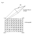
- a finite element is generated from every three neighboring pixels in the distance image (EB) (FIG ). More specifically, each of three vectors belonging to adjacent pixels in the EB form the vertices of a triangle in the earth-fixed coordinate system (KS). By fitting the EB partition into sets of three adjacent pixels, one obtains a coherent surface in the space that models the scanned scene.
- Pixels in the EB that are missing are ignored; i.e. all the FEs for which the pixel in question would not come to fruition.
- the modeled Scene surface may well have holes.
- the domain of definition for this representation is, of course, limited to the vertical projection of the FE onto the x, y plane, and is therefore triangular.
- a terrain course function z G ( x, y ) in the ground-fixed coordinate system with a vertical z-axis available.
- a regular square grid with a rectangular boundary is placed over the x, y plane.
- the step size ie the desired cell size in the HK, can be set.
- Above each node of this grid is either a FE (typical terrain course), multiple FEs (complex scene, eg forest), or no FE (miss point in EB or exit from EBK field of view).
- the maximum value of the z-values of all FEs is used at this point, in whose respective definition ranges the node falls.
- the terrain progression function at the node in question is initially not assigned a value; a substitute value will be inserted later, so that later computation steps remain feasible; see. the section approximation and continuation of G by a plane.
- the terrain trajectory function has succeeded in projecting the sensor data into a unique discrete function defined in the ground-based coordinate system and on a regular grid, which is more easily accessible to further processing than the original point cloud.
- G describes the "upper envelope" of the scene.
- the so-called confidence function z T ( x, y ) introduced on the same rectangular, uniform x, y grid as G.
- T indicates, with a value between 1 and 0 at each node, whether the respective value of G is more or less close to an actual EBK measurement point and therefore more or less trustworthy.
- the metric used here takes into account the horizontal density of the measuring points, as it would be on perfectly level terrain. This means that in the far field of the HK larger horizontal distances to actual measuring points are allowed than in the near field, without losing the confidence.
- the confidence function is a suitable means of detecting transverse Trenches also from a relatively long distance and has therefore for the Trench detection proved indispensable.
- HK areas are becoming smaller Confidence coded with its own color (white in this example). With As the distance to the trench decreases they become smaller as the distance increases whose reason is illuminated.
- ⁇ represents the desired HK code, which classifies the terrain at the node concerned as a trench point, passable point, etc.
- the ground level function basically follows the actual terrain floor, but cuts off positive, isolated obstacles such as piles, boulders, trees, etc. (see Fig. 5) and spans negative obstacles such as ditches and holes.
- H 1 means negative obstacle in the place ( x, y );
- G ( x, y )> A ( x, y ) + H 2 means positive obstacle on the spot ( x, y ) h 1 > 0 and h 2 > 0 are small, positive thresholds that suppress minor deviations between G ( x, y ) and A ( x, y ).
- Each terrain assessment procedure must be able to handle three basic types of obstacles: positive obstacles, negative obstacles, and step obstacles.
- the recognition of positive and negative obstacles succeeds, as explained, by comparing G ( x, y ) with A ( x, y )
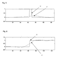
- For terrain steps see Fig. 6) the comparison of G ( x, y ) with A ( x, y ) to detect a positive obstacle on one side of the step and a trench on the other.
- the detected trench is a virtual one, this still reliably warns against terrain levels, especially as the trenches can not later be classified as bridgeable (see below, point 4).
- the reliable step detection is also achieved by the high slope amount of G ( x, y ) at the location of the step.
- a ( x , y ) no longer spans this, but touches the trench bottom at least in the trench center.
- the trench is no longer interpreted as a single interrelated obstacle, but as a result of two obstacles representing terrain levels: a downgrade and an upgrade.
- the trench bottom can basically be classified as passable again. This is quite desirable, what you can do with the example of a dried river bed or similar. can understand.
- the terrain smoothing feature is subjected to a first smoothing step.
- a first smoothing step This is on For example, a two-dimensional, four-level Discrete Wavelet Transformation (DWT) is performed on its rectangular domain.
- DWT Discrete Wavelet Transformation
- a total of 13 subbands are obtained.
- the reconstructed signal B represents the desired smoothing of the original signal.
- B is defined on the same grid as ,
- B is still characterized by relatively strong overshoots (similar to Gibbs ringing in the Fourier transform) that can occur near large positive obstacles. With B , therefore, large positive obstacles are first recognized and eliminated removed in order to obtain by subsequent, second smoothing a better approximation A of the soil course.
- Second smoothing step - The terrain course function G and so obtained is now as before Smoothed by DWT. This leads to a better B than the second ground course function A with considerably weaker overshoots.
- the terrain evaluation function Z from which the color coding of the HK can be derived, is calculated below.
- the terrain evaluation function ⁇ Z ( x, y ) defined on the same discrete grid as the functions G ( x, y ) and A ( x, y ) assumes different values that are used in the generation of HK be coded as colors on this grid.
- a low amount of the gradient results in green coding of the associated one Node, which signals drivability.
- a high amount of the gradient can be both of local roughness of the terrain as well as of significant global Terrain slope originate. In any case, starting from a certain amount encodes a yellow color, and the normalized direction of the gradient is at each such nodes are shown as a black arrow. About a maximum value Gradient amounts going beyond, such as obstacles, lead to the value 1 of the Terrain evaluation function, and thus also to red coloring (without arrows) in the HK.
- FIG. 3 An example of an obstacle card encoded according to the invention for the original scene 1 is shown in Fig. 3.
- the sensor position is in the middle of the bottom edge of the image, and the line of sight is horizontal over the representation of bottom up.
- Trench Detection To create ditch bridging suggestions, you must first identify elongated, not too wide trenches. This can be done as follows: it becomes from the terrain evaluation function a normalized "trench signal" which is filtered with normalized trench templates of various widths and directions ("matched filtering" method, see point 2 of the below implementation examples). If the filter result at a node exceeds a defined threshold, it can be assumed that a trench structure corresponding to the template is located here. The method is fundamentally robust because of its integrating character.
- the trench edges defined by the condition Z ( x, y )> -1 prove to be unstable, which is related to the forward looking sensor geometry and the imprecise detection of the front trench edge in transverse trenches.
- the opposite edge of such a trench generally proves to be good in real test data, so that by means of - instead of looking for the trenches themselves - looking for elongated and narrow trench edges.
- the x, y grid is probed perpendicular to the trench direction associated with the node.
- the z-values of the terrain course function G and the ground course function A are compared at each new node. As long as G is below A , it continues in the specified direction; once this is no longer fulfilled, the crossing is completed. This is done from the edge point in both possible directions.
- Crossing routes that are longer than a user-specified maximum length are not permitted.
- the entire route is validated only if there is a blue node or a low confidence node somewhere on it; because crossing routes should not be looked for over minor terrain waves (which are passable), but only over real trenches.
- the calculation of a route is aborted if, in the route formation, one encounters a red-coded node of the terrain evaluation function or a node undefined for G ; that is to say, trying to cross into or out of the obstacle.
- the thus determined crossing routes are coded as crossing recommendation.
- a continuous confidence function z T ( x, y ) is constructed, from which the discrete confidence function is calculated by evaluation according to (*).
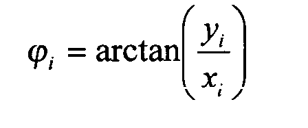
- the scanning mechanism of the sensor should have a vertical and a horizontal axis such that the scan directions - such as polar coordinates - can be described by means of an azimuth angle ⁇ and an elevation angle ⁇ .
- the radial resolution of the curvilinear grid on the ground is approximately through given.
- ⁇ depends on the considered location point ( x, y ) on the ground, as well as on the height of the sensor above this ground.
- the total confidence function can now be constructed as follows, taking into account all existing measurement points:
- the analysis filter-in the present case a direction-oriented trench template of defined width-with the signal to be analyzed-in the present case the normalized trench (edge) function W ( x, y ) (see above description of the method step "overcoming trenches”). ) folded.
- the convolution signal takes values between -1 and 1, indicating for each location ( x, y ) how much the analysis filter "fits" (-1 for no fit, 1 for exact fit, 0 for flat terrain).
- Each new analysis filter has its own convolution signal, which is compared with the other convolution signals.
- the largest convolution signal at a location ( x, y ) corresponds most closely to the actual orientation and width of a trench in the analyzed signal. If this maximum signal exceeds a certain threshold, it is assumed that there is a trench of the relevant orientation and width at that location.
- the parameter b defines the trench width. As can be seen in FIG. 8, there is also a trench length a . However, this parameter is not varied in contrast to b and k , but is the same for all templates, and corresponds approximately to the vehicle width.
- the analysis filters like the other functions in the HK, are defined on the nodes of a square grid.
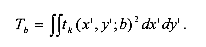
- the direction and width dependent convolution integral is at location ( x, y ) with the normalization factor
- the numerical value -1 ⁇ F k ( x , y ; b ) ⁇ 1 thus indicates how well the signal U ( x , y ) at the location ( x, y ) matches the template t k ( x ', y'; b ) is correlated.
- u 0.5
Landscapes
- Engineering & Computer Science (AREA)
- Physics & Mathematics (AREA)
- Computer Networks & Wireless Communication (AREA)
- General Physics & Mathematics (AREA)
- Radar, Positioning & Navigation (AREA)
- Remote Sensing (AREA)
- Electromagnetism (AREA)
- Traffic Control Systems (AREA)
- Image Processing (AREA)
- Measurement Of Optical Distance (AREA)
Abstract
Description
- Erzeugung eines Entfernungsbilds des Geländes mittels eines entfernungsbildgebenden Sensors;
- Umrechnung der Sensordaten in eine räumliche Fläche, die aus einzelnen finiten Flächenelementen besteht und die die vom Sensor abgetastete Szene modelliert, und Projektion der räumlichen Fläche auf eine in einem erdfesten Koordinatensystem dargestellten Geländeverlaufsfunktion;
- stetige Fortsetzung der Geländeverlaufsfunktion an undefinierten Stellen;
- Erzeugung einer Konfidenzfunktion für die Geländeverlaufsfunktion in demselben Koordinatensystem wie die Geländeverlaufsfunktion, wobei die Konfidenzfunktion ein Maß für die Vertrauenswürdigkeit der Geländeverlaufsfunktion darstellt und abhängig ist vom Abstand eines Wertes der Geländeverlaufsfunktion von einem Sensormesspunkt;
- Erzeugung einer Bodenverlaufsfunktion durch Glättung der Geländeverlaufsfunktion;
- Erzeugung einer Geländebewertungsfunktion durch Auswertung des Steigungsverhaltens der Geländeverlaufsfunktion, durch Vergleich der Geländeverlaufsfunktion mit der Bodenverlaufsfunktion sowie durch Auswertung der Konfidenzfunktion ;
- Klassifikation des Geländes hinsichtlich seiner Befahrbarkeit unter Verwendung der Geländebewertungsfunktion Diese Klassifizierumg kann in Form einer so genannten Hinderniskarte (HK) dargestellt werden, in der die einzelnen Geländeklassen (z.B. befahrbares Gelände, negative Hindernisse (Vertiefungen), positive Hindernisse) farblich kodiert werden.
- Filterung der Geländebewertungsfunktion mit Grabenschablonen verschiedener Breiten und Richtungen gemäß der Methode des Matched Filtering zur Ermittlung des Grabenverlaufs oder Grabenrandverlaufs,
- Suche nach möglichen Routen zur Grabenüberquerung, ausgehend von erkannten Grabenrandpunkten und senkrecht zum Grabenrand verlaufend, und Validierung der Route mittels Verwendung der Gelände-, der Bodenverlaufs- und der Konfidenzfunktion.
- Größe: 64 x 128 (vertikal x horizontal)
- Gesichtsfeld: 30° x 60° (vertikal x horizontal)
- Winkelauflösung: ca. 0.5° in beiden Richtungen
- Messreichweite: ca. 50 m
- Messauflösung in Messrichtung: 3 cm


| HK-Code | Bedeutung für kodierten Gitterknoten | |
| Farbdarstellung | Zahlendarstellung λ = Z(xk,yl ) | |
| weiß | -2 | Knoten ist abgeschattet (z.B. hinter Hindernis oder außerhalb Sensorgesichtsfeld) oder weist nur einen geringen Konfidenzwert auf |
| blau | -1 | negatives Hindernis (=Graben) |
| blau mit rotem Pfeil | (-0,99) - (-0,01) | Graben, der in der Pfeilrichtung (oder dazu entgegengesetzt) überquerbar ist (Die fahrzeugabhängige, maximale Grabenbreite ist als Verfahrensparameter einstellbar.) |
| grün | 0 - 0,49 | Befahrbarkeit |
| gelb mit schwarzem Pfeil | 0,5 - 0,99 | eingeschränkte Befahrbarkeit des Geländes; nur in der Richtung des Pfeiles (oder dazu entgegengesetzt) kann gefahren werden |
| rot | 1 | positives Hindernis |







- G
- Geländeverlaufsfunktion
- A
- Bodenverlaufsfunktion
- T
- Konfidenzfunktion
- Z
- Geländebewertungsfunktion
- HK
- Hinderniskarte
- FE
- Finites Flächenelement
- EBK
- Entfernungsbildkamera
- EB
- Entfernungsbild
- KS
- Koordinatensystem
- DWT
- Diskrete Wavelet Transformation
Claims (5)
- Verfahren zur Hinderniserkennung und Geländeklassifikation für Geländefahrzeuge mit folgenden VerfahrensschrittenErzeugung eines Entfernungsbilds des Geländes mittels eines entfernungsbildgebenden Sensors;Umrechnung der Sensordaten in eine räumliche Fläche, die aus einzelnen finiten Flächenelementen besteht und die die vom Sensor abgetastete Szene modelliert, und Projektion der räumlichen Fläche auf eine in einem erdfesten Koordinatensystem dargestellten Geländeverlaufsfunktion;stetige Fortsetzung der Geländeverlaufsfunktion an undefinierten Stellen;Erzeugung einer Konfidenzfunktion für die Geländeverlaufsfunktion in demselben Koordinatensystem wie die Geländeverlaufsfunktion, wobei die Konfidenzfunktion ein Maß für die Vertrauenswürdigkeit der Geländeverlaufsfunktion darstellt und abhängig ist vom Abstand eines Werts der Geländeverlaufsfunktion von einem Sensormesspunkt;Erzeugung einer Bodenverlaufsfunktion durch Glättung der Geländeverlaufsfunktion;Erzeugung einer Geländebewertungsfunktion durch Auswertung des Steigungsverhaltens der Geländeverlaufsfunktion, durch Vergleich der Geländeverlaufsfunktion mit der Bodenverlaufsfunktion sowie durch Auswertung der Konfidenzfunktion;Klassifikation des Geländes hinsichtlich seiner Befahrbarkeit unter Verwendung der Geländebewertungsfunktion.
- Verfahren nach Anspruch 1, dadurch gekennzeichnet, dass eine für das Fahrzeug mögliche Route zur Überquerung der im Gelände vorhandenen Gräben mittels folgender Verfahrensschritte erkannt wird:Filterung der Geländebewertungsfunktion mit Grabenschablonen verschiedener Breiten und Richtungen gemäß der Methode des Matched Filtering zur Ermittlung des Grabenverlaufs oder Grabenrandverlaufs,Suche nach möglichen Routen zur Grabenüberquerungen, von erkannten Grabenrandpunkten ausgehend und senkrecht zum Grabenrand verlaufend, und Validierung der Route mittels Verwendung der Gelände-, der Bodenverlaufs- und der Konfidenzfunktion.
- Verfahren nach einem der vorangehenden Ansprüche, dadurch gekennzeichnet, dass die stetige Fortsetzung der Geländeverlaufsfunktion an undefinierten Stellen derart durchgeführt wird, dass eine lineare, zweidimensionale Ebene in die Szene gelegt wird, deren Optimalparameter aus der Geländeverlaufsfunktion in ihrem verfügbaren Definitionsbereich mittels Hough-Transformation berechnet werden.
- Verfahren nach einem der vorangehenden Ansprüche, dadurch gekennzeichnet, dass die Glättung der Geländeverlaufsfunktion zur Ermittlung der Bodenverlaufsfunktion in zwei Stufen mit jeweils einer diskreten Wavelet-Transformation erfolgt, wobei in einem Zwischenschritt zwischen den beiden Stufen zunächst große Hindernisse entfernt werden.
- Verfahren nach einem der vorangehenden Ansprüche, dadurch gekennzeichnet, dass die finiten Flächenelemente Dreieckselemente sind.
Applications Claiming Priority (2)
| Application Number | Priority Date | Filing Date | Title |
|---|---|---|---|
| DE10330011A DE10330011B4 (de) | 2003-07-03 | 2003-07-03 | Verfahren zur Hinderniserkennung und Geländeklassifikation |
| DE10330011 | 2003-07-03 |
Publications (2)
| Publication Number | Publication Date |
|---|---|
| EP1494044A1 true EP1494044A1 (de) | 2005-01-05 |
| EP1494044B1 EP1494044B1 (de) | 2006-08-16 |
Family
ID=33426843
Family Applications (1)
| Application Number | Title | Priority Date | Filing Date |
|---|---|---|---|
| EP04012678A Expired - Lifetime EP1494044B1 (de) | 2003-07-03 | 2004-05-28 | Verfahren zur Hinderniserkennung und Geländeklassifikation |
Country Status (4)
| Country | Link |
|---|---|
| US (1) | US20050024492A1 (de) |
| EP (1) | EP1494044B1 (de) |
| AT (1) | ATE336729T1 (de) |
| DE (1) | DE10330011B4 (de) |
Cited By (4)
| Publication number | Priority date | Publication date | Assignee | Title |
|---|---|---|---|---|
| CN103927543A (zh) * | 2014-04-24 | 2014-07-16 | 山东大学(威海) | 一种基于dem的月表撞击坑自动识别和边界提取方法 |
| EP3255457A1 (de) * | 2016-06-08 | 2017-12-13 | Aisin Seiki Kabushiki Kaisha | Abstandsmessvorrichtung |
| CN113743228A (zh) * | 2018-12-10 | 2021-12-03 | 百度在线网络技术(北京)有限公司 | 基于多数据融合结果的障碍物存在性检测方法和装置 |
| CN119293135A (zh) * | 2024-12-10 | 2025-01-10 | 云南高阳科技有限公司 | 测绘和地理信息成果自动分类设计模型 |
Families Citing this family (28)
| Publication number | Priority date | Publication date | Assignee | Title |
|---|---|---|---|---|
| DE102005024735B4 (de) * | 2005-05-31 | 2007-06-28 | Rheinmetall Landsysteme Gmbh | Verfahren zur Entfernungsbestimmung und Anzeige, sowie Entfernungsmesssystem, insbesondere zur Unterstützung für das Verlegen einer Brücke |
| US7969488B2 (en) * | 2005-08-03 | 2011-06-28 | Micron Technologies, Inc. | Correction of cluster defects in imagers |
| US8527155B2 (en) * | 2008-06-27 | 2013-09-03 | Caterpillar Inc. | Worksite avoidance system |
| US8099205B2 (en) * | 2008-07-08 | 2012-01-17 | Caterpillar Inc. | Machine guidance system |
| US8755997B2 (en) * | 2008-07-30 | 2014-06-17 | Honeywell International Inc. | Laser ranging process for road and obstacle detection in navigating an autonomous vehicle |
| US8364334B2 (en) * | 2008-10-30 | 2013-01-29 | Honeywell International Inc. | System and method for navigating an autonomous vehicle using laser detection and ranging |
| US8140239B2 (en) | 2008-12-17 | 2012-03-20 | Caterpillar Inc. | Slippage condition response system |
| US8073609B2 (en) * | 2008-12-17 | 2011-12-06 | Caterpillar Inc. | Slippage condition response system |
| US8532863B2 (en) * | 2009-09-28 | 2013-09-10 | Sri International | Audio based robot control and navigation |
| CN101701818B (zh) * | 2009-11-05 | 2011-03-30 | 上海交通大学 | 远距离障碍的检测方法 |
| AU2010200146A1 (en) * | 2010-01-14 | 2011-07-28 | The University Of Sydney | Extraction processes |
| AU2010200144A1 (en) * | 2010-01-14 | 2011-07-28 | The University Of Sydney | Extraction processes |
| CN101813475B (zh) * | 2010-04-24 | 2011-06-01 | 上海交通大学 | 远距离障碍的自适应检测方法 |
| US20120166110A1 (en) * | 2010-12-27 | 2012-06-28 | Jonathan Paul Wilson | Method and system for component resistance to flow |
| US9062983B2 (en) | 2013-03-08 | 2015-06-23 | Oshkosh Defense, Llc | Terrain classification system for a vehicle |
| US9097520B2 (en) | 2013-06-12 | 2015-08-04 | Caterpillar Inc. | System and method for mapping a raised contour |
| US10140870B1 (en) | 2015-09-30 | 2018-11-27 | Waymo Llc | Occupant facing vehicle display |
| DE102016224530B3 (de) * | 2016-12-08 | 2018-01-18 | Man Truck & Bus Ag | Verfahren zur Bodenoberflächenschätzung |
| DE102017203276B4 (de) | 2017-03-01 | 2022-10-06 | Volkswagen Aktiengesellschaft | Verfahren und Vorrichtung zur Ermittlung einer Trajektorie in Off-road-Szenarien |
| KR102415357B1 (ko) * | 2018-04-20 | 2022-07-01 | 프랫 앤 밀러 엔지니어링 앤드 페브리케이션, 인코포레이티드 | 다중 모드 극한 이동 서스펜션 접지면 감지 및 제어기를 갖는 자동차 |
| DE102018208205A1 (de) * | 2018-05-24 | 2019-11-28 | Ford Global Technologies, Llc | Verfahren zum Kartographieren der Umgebung von Kraftfahrzeugen |
| US11810251B2 (en) | 2019-10-03 | 2023-11-07 | General Electric Company | Remote sensing method to model terrain shape by detecting reliable ground points |
| GB202311795D0 (en) | 2019-12-19 | 2023-09-13 | Motional Ad Llc | Foreground extraction using surface fitting |
| US11792644B2 (en) | 2021-06-21 | 2023-10-17 | Motional Ad Llc | Session key generation for autonomous vehicle operation |
| US12548319B2 (en) | 2022-09-23 | 2026-02-10 | Ford Global Technologies, Llc | Satellite-enabled off-road obstacle detection |
| CN115546426A (zh) * | 2022-10-09 | 2022-12-30 | 网易(杭州)网络有限公司 | 地形场景生成方法、装置、计算机设备和存储介质 |
| WO2025197223A1 (ja) * | 2024-03-21 | 2025-09-25 | 株式会社Jvcケンウッド | 測距装置及び測距方法 |
| CN121403362A (zh) * | 2025-10-24 | 2026-01-27 | 清华大学 | 一种机器人控制方法及装置 |
Family Cites Families (3)
| Publication number | Priority date | Publication date | Assignee | Title |
|---|---|---|---|---|
| FR2693011B1 (fr) * | 1992-06-29 | 1994-09-23 | Matra Sep Imagerie Inf | Procédé et dispositif de surveillance d'une scène tridimensionnelle, mettant en Óoeuvre des capteurs d'imagerie. |
| US5825915A (en) * | 1995-09-12 | 1998-10-20 | Matsushita Electric Industrial Co., Ltd. | Object detecting apparatus in which the position of a planar object is estimated by using hough transform |
| US7149611B2 (en) * | 2003-02-21 | 2006-12-12 | Lockheed Martin Corporation | Virtual sensor mast |
-
2003
- 2003-07-03 DE DE10330011A patent/DE10330011B4/de not_active Expired - Fee Related
-
2004
- 2004-05-28 AT AT04012678T patent/ATE336729T1/de not_active IP Right Cessation
- 2004-05-28 EP EP04012678A patent/EP1494044B1/de not_active Expired - Lifetime
- 2004-07-02 US US10/882,668 patent/US20050024492A1/en not_active Abandoned
Non-Patent Citations (2)
| Title |
|---|
| CHEN-CHAU CHU ET AL: "MULTI-SENSOR IMAGE INTERPRETATION USING LASER RADAR AND THERMAL IMAGES", PROCEEDINGS OF THE CONFERENCE ON ARTIFICIAL INTELLIGENCE APPLICATIONS. MIAMI BEACH, FEB. 24 - 28, 1991, NEW YORK, IEEE, US, vol. VOL. 1 CONF. 7, 24 February 1991 (1991-02-24), pages 190 - 196, XP000298923, ISBN: 0-8186-2135-4 * |
| IN SO KWEON ET AL: "HIGH-RESOLUTION TERRAIN MAP FROM MULTIPLE SENSOR DATA", IEEE TRANSACTIONS ON PATTERN ANALYSIS AND MACHINE INTELLIGENCE, IEEE INC. NEW YORK, US, vol. 14, no. 2, 1 February 1992 (1992-02-01), pages 278 - 292, XP000248484, ISSN: 0162-8828 * |
Cited By (6)
| Publication number | Priority date | Publication date | Assignee | Title |
|---|---|---|---|---|
| CN103927543A (zh) * | 2014-04-24 | 2014-07-16 | 山东大学(威海) | 一种基于dem的月表撞击坑自动识别和边界提取方法 |
| CN103927543B (zh) * | 2014-04-24 | 2015-12-09 | 山东大学(威海) | 一种基于dem的月表撞击坑自动识别和边界提取方法 |
| EP3255457A1 (de) * | 2016-06-08 | 2017-12-13 | Aisin Seiki Kabushiki Kaisha | Abstandsmessvorrichtung |
| CN113743228A (zh) * | 2018-12-10 | 2021-12-03 | 百度在线网络技术(北京)有限公司 | 基于多数据融合结果的障碍物存在性检测方法和装置 |
| CN113743228B (zh) * | 2018-12-10 | 2023-07-14 | 百度在线网络技术(北京)有限公司 | 基于多数据融合结果的障碍物存在性检测方法和装置 |
| CN119293135A (zh) * | 2024-12-10 | 2025-01-10 | 云南高阳科技有限公司 | 测绘和地理信息成果自动分类设计模型 |
Also Published As
| Publication number | Publication date |
|---|---|
| US20050024492A1 (en) | 2005-02-03 |
| DE10330011A1 (de) | 2005-02-17 |
| ATE336729T1 (de) | 2006-09-15 |
| EP1494044B1 (de) | 2006-08-16 |
| DE10330011B4 (de) | 2005-05-12 |
Similar Documents
| Publication | Publication Date | Title |
|---|---|---|
| EP1494044B1 (de) | Verfahren zur Hinderniserkennung und Geländeklassifikation | |
| DE69624614T2 (de) | Verfahren zur Stereoübereinstimmungs- und Ungleichheitsmessung | |
| Höfle et al. | Urban vegetation detection using radiometrically calibrated small-footprint full-waveform airborne LiDAR data | |
| EP0396867B1 (de) | Navigationsverfahren | |
| DE69811050T2 (de) | Rekonstruktionsverfahren, Vorrichtung und Dekodierungssystem für dreidimensionalen Szenen. | |
| DE19943325C2 (de) | Verfahren zur Bearbeitung seismischer Meßdaten mit einem neuronalen Netzwerk | |
| EP2418510B1 (de) | Verfahren zur Beurteilung einer Bodenfläche auf deren Eignung als Landezone oder Rollfläche für Luftfahrzeuge | |
| Bakuła et al. | Testing of land cover classification from multispectral airborne laser scanning data | |
| Rieger et al. | Roads and buildings from laser scanner data within a forest enterprise | |
| DE102011111440A1 (de) | Verfahren zur Umgebungsrepräsentation | |
| DE202009013865U1 (de) | Konzept zum Auswählen eines optimierten Bewertungsmerkmalsteilsatzes für eine Inspektion von Freiformoberflächen und Konzept zum Inspizieren einer Freiformoberfläche | |
| DE102006057552A1 (de) | System und Verfahren zur Messung des Abstands eines vorausfahrenden Fahrzeugs | |
| CH716789B1 (de) | Verfahren zur Extraktion verborgener geologischer Strukturinformationen aus einem Fernerkundung-Bildpaar. | |
| DE3808173A1 (de) | System zum detektieren unterirdischer objekte | |
| DE102014205083B3 (de) | Erstellen von Karten mit Küstenlinien | |
| DE102023200930B4 (de) | Objektposition-erkennungsvorrichtung | |
| EP1141883B1 (de) | Verfahren zum vergleichen von punktmengen | |
| DE102020200728A1 (de) | Rekonstruieren von Elevationsinformationen aus Radardaten | |
| EP2921879B1 (de) | Klassifikationsverfahren für Messpunkte eines topobathymetrischen Datensatzes | |
| AT11770U1 (de) | Verfahren zur auswahl eines optimierten auswerteuntermerkmals zur kontrolle einer freiformfläche und verfahren zur kontrolle einer freiformfläche | |
| Tian | 3D change detection from high and very high resolution satellite stereo imagery | |
| Tóvári | Segmentation based classification of airborne laser scanner data | |
| DE102019209204A1 (de) | Detektionslokalisierung von verfügbarem parkraum unter verwendung von verschiebung basierend auf historischer aggregation | |
| DE102023113349A1 (de) | Verfahren zum Bestimmen einer vertikalen Struktur eines halbtransparenten Mediums aus SAR-Daten eines SAR-Systems | |
| DE19627938A1 (de) | Verfahren zur dynamischen Spurverfolgung in Bewegtbildsequenzen |
Legal Events
| Date | Code | Title | Description |
|---|---|---|---|
| PUAI | Public reference made under article 153(3) epc to a published international application that has entered the european phase |
Free format text: ORIGINAL CODE: 0009012 |
|
| AK | Designated contracting states |
Kind code of ref document: A1 Designated state(s): AT BE BG CH CY CZ DE DK EE ES FI FR GB GR HU IE IT LI LU MC NL PL PT RO SE SI SK TR |
|
| AX | Request for extension of the european patent |
Extension state: AL HR LT LV MK |
|
| 17P | Request for examination filed |
Effective date: 20050609 |
|
| AKX | Designation fees paid |
Designated state(s): AT BE BG CH CY CZ DE DK EE ES FI FR GB GR HU IE IT LI LU MC NL PL PT RO SE SI SK TR |
|
| GRAP | Despatch of communication of intention to grant a patent |
Free format text: ORIGINAL CODE: EPIDOSNIGR1 |
|
| GRAS | Grant fee paid |
Free format text: ORIGINAL CODE: EPIDOSNIGR3 |
|
| GRAA | (expected) grant |
Free format text: ORIGINAL CODE: 0009210 |
|
| AK | Designated contracting states |
Kind code of ref document: B1 Designated state(s): AT BE BG CH CY CZ DK EE ES FI FR GB GR HU IE IT LI LU MC NL PL PT RO SE SI SK TR |
|
| PG25 | Lapsed in a contracting state [announced via postgrant information from national office to epo] |
Ref country code: SK Free format text: LAPSE BECAUSE OF FAILURE TO SUBMIT A TRANSLATION OF THE DESCRIPTION OR TO PAY THE FEE WITHIN THE PRESCRIBED TIME-LIMIT Effective date: 20060816 Ref country code: SI Free format text: LAPSE BECAUSE OF FAILURE TO SUBMIT A TRANSLATION OF THE DESCRIPTION OR TO PAY THE FEE WITHIN THE PRESCRIBED TIME-LIMIT Effective date: 20060816 Ref country code: PL Free format text: LAPSE BECAUSE OF FAILURE TO SUBMIT A TRANSLATION OF THE DESCRIPTION OR TO PAY THE FEE WITHIN THE PRESCRIBED TIME-LIMIT Effective date: 20060816 Ref country code: CZ Free format text: LAPSE BECAUSE OF FAILURE TO SUBMIT A TRANSLATION OF THE DESCRIPTION OR TO PAY THE FEE WITHIN THE PRESCRIBED TIME-LIMIT Effective date: 20060816 Ref country code: FI Free format text: LAPSE BECAUSE OF FAILURE TO SUBMIT A TRANSLATION OF THE DESCRIPTION OR TO PAY THE FEE WITHIN THE PRESCRIBED TIME-LIMIT Effective date: 20060816 Ref country code: IE Free format text: LAPSE BECAUSE OF FAILURE TO SUBMIT A TRANSLATION OF THE DESCRIPTION OR TO PAY THE FEE WITHIN THE PRESCRIBED TIME-LIMIT Effective date: 20060816 Ref country code: NL Free format text: LAPSE BECAUSE OF FAILURE TO SUBMIT A TRANSLATION OF THE DESCRIPTION OR TO PAY THE FEE WITHIN THE PRESCRIBED TIME-LIMIT Effective date: 20060816 Ref country code: RO Free format text: LAPSE BECAUSE OF FAILURE TO SUBMIT A TRANSLATION OF THE DESCRIPTION OR TO PAY THE FEE WITHIN THE PRESCRIBED TIME-LIMIT Effective date: 20060816 Ref country code: IT Free format text: LAPSE BECAUSE OF FAILURE TO SUBMIT A TRANSLATION OF THE DESCRIPTION OR TO PAY THE FEE WITHIN THE PRESCRIBED TIME-LIMIT;WARNING: LAPSES OF ITALIAN PATENTS WITH EFFECTIVE DATE BEFORE 2007 MAY HAVE OCCURRED AT ANY TIME BEFORE 2007. THE CORRECT EFFECTIVE DATE MAY BE DIFFERENT FROM THE ONE RECORDED. Effective date: 20060816 |
|
| REG | Reference to a national code |
Ref country code: GB Ref legal event code: FG4D Free format text: NOT ENGLISH |
|
| REG | Reference to a national code |
Ref country code: CH Ref legal event code: EP |
|
| REG | Reference to a national code |
Ref country code: IE Ref legal event code: FG4D Free format text: LANGUAGE OF EP DOCUMENT: GERMAN |
|
| PG25 | Lapsed in a contracting state [announced via postgrant information from national office to epo] |
Ref country code: SE Free format text: LAPSE BECAUSE OF FAILURE TO SUBMIT A TRANSLATION OF THE DESCRIPTION OR TO PAY THE FEE WITHIN THE PRESCRIBED TIME-LIMIT Effective date: 20061116 Ref country code: DK Free format text: LAPSE BECAUSE OF FAILURE TO SUBMIT A TRANSLATION OF THE DESCRIPTION OR TO PAY THE FEE WITHIN THE PRESCRIBED TIME-LIMIT Effective date: 20061116 Ref country code: BG Free format text: LAPSE BECAUSE OF FAILURE TO SUBMIT A TRANSLATION OF THE DESCRIPTION OR TO PAY THE FEE WITHIN THE PRESCRIBED TIME-LIMIT Effective date: 20061116 |
|
| GBT | Gb: translation of ep patent filed (gb section 77(6)(a)/1977) |
Effective date: 20061031 |
|
| PG25 | Lapsed in a contracting state [announced via postgrant information from national office to epo] |
Ref country code: ES Free format text: LAPSE BECAUSE OF FAILURE TO SUBMIT A TRANSLATION OF THE DESCRIPTION OR TO PAY THE FEE WITHIN THE PRESCRIBED TIME-LIMIT Effective date: 20061127 |
|
| PG25 | Lapsed in a contracting state [announced via postgrant information from national office to epo] |
Ref country code: PT Free format text: LAPSE BECAUSE OF FAILURE TO SUBMIT A TRANSLATION OF THE DESCRIPTION OR TO PAY THE FEE WITHIN THE PRESCRIBED TIME-LIMIT Effective date: 20070116 |
|
| NLV1 | Nl: lapsed or annulled due to failure to fulfill the requirements of art. 29p and 29m of the patents act | ||
| ET | Fr: translation filed | ||
| REG | Reference to a national code |
Ref country code: IE Ref legal event code: FD4D |
|
| PLBE | No opposition filed within time limit |
Free format text: ORIGINAL CODE: 0009261 |
|
| STAA | Information on the status of an ep patent application or granted ep patent |
Free format text: STATUS: NO OPPOSITION FILED WITHIN TIME LIMIT |
|
| 26N | No opposition filed |
Effective date: 20070518 |
|
| BERE | Be: lapsed |
Owner name: EADS DEUTSCHLAND G.M.B.H. Effective date: 20070531 |
|
| PG25 | Lapsed in a contracting state [announced via postgrant information from national office to epo] |
Ref country code: MC Free format text: LAPSE BECAUSE OF NON-PAYMENT OF DUE FEES Effective date: 20070531 |
|
| PG25 | Lapsed in a contracting state [announced via postgrant information from national office to epo] |
Ref country code: BE Free format text: LAPSE BECAUSE OF NON-PAYMENT OF DUE FEES Effective date: 20070531 |
|
| PG25 | Lapsed in a contracting state [announced via postgrant information from national office to epo] |
Ref country code: GR Free format text: LAPSE BECAUSE OF FAILURE TO SUBMIT A TRANSLATION OF THE DESCRIPTION OR TO PAY THE FEE WITHIN THE PRESCRIBED TIME-LIMIT Effective date: 20061117 |
|
| PG25 | Lapsed in a contracting state [announced via postgrant information from national office to epo] |
Ref country code: EE Free format text: LAPSE BECAUSE OF FAILURE TO SUBMIT A TRANSLATION OF THE DESCRIPTION OR TO PAY THE FEE WITHIN THE PRESCRIBED TIME-LIMIT Effective date: 20060816 |
|
| PG25 | Lapsed in a contracting state [announced via postgrant information from national office to epo] |
Ref country code: AT Free format text: LAPSE BECAUSE OF NON-PAYMENT OF DUE FEES Effective date: 20070528 |
|
| PGRI | Patent reinstated in contracting state [announced from national office to epo] |
Ref country code: IT Effective date: 20080601 |
|
| REG | Reference to a national code |
Ref country code: CH Ref legal event code: PL |
|
| PG25 | Lapsed in a contracting state [announced via postgrant information from national office to epo] |
Ref country code: CH Free format text: LAPSE BECAUSE OF NON-PAYMENT OF DUE FEES Effective date: 20080531 Ref country code: LI Free format text: LAPSE BECAUSE OF NON-PAYMENT OF DUE FEES Effective date: 20080531 |
|
| PG25 | Lapsed in a contracting state [announced via postgrant information from national office to epo] |
Ref country code: LU Free format text: LAPSE BECAUSE OF NON-PAYMENT OF DUE FEES Effective date: 20070528 Ref country code: CY Free format text: LAPSE BECAUSE OF FAILURE TO SUBMIT A TRANSLATION OF THE DESCRIPTION OR TO PAY THE FEE WITHIN THE PRESCRIBED TIME-LIMIT Effective date: 20060816 |
|
| PG25 | Lapsed in a contracting state [announced via postgrant information from national office to epo] |
Ref country code: TR Free format text: LAPSE BECAUSE OF FAILURE TO SUBMIT A TRANSLATION OF THE DESCRIPTION OR TO PAY THE FEE WITHIN THE PRESCRIBED TIME-LIMIT Effective date: 20060816 Ref country code: HU Free format text: LAPSE BECAUSE OF FAILURE TO SUBMIT A TRANSLATION OF THE DESCRIPTION OR TO PAY THE FEE WITHIN THE PRESCRIBED TIME-LIMIT Effective date: 20070217 |
|
| PGFP | Annual fee paid to national office [announced via postgrant information from national office to epo] |
Ref country code: FR Payment date: 20110607 Year of fee payment: 8 |
|
| PGFP | Annual fee paid to national office [announced via postgrant information from national office to epo] |
Ref country code: GB Payment date: 20110520 Year of fee payment: 8 |
|
| PGFP | Annual fee paid to national office [announced via postgrant information from national office to epo] |
Ref country code: IT Payment date: 20110523 Year of fee payment: 8 |
|
| GBPC | Gb: european patent ceased through non-payment of renewal fee |
Effective date: 20120528 |
|
| PG25 | Lapsed in a contracting state [announced via postgrant information from national office to epo] |
Ref country code: IT Free format text: LAPSE BECAUSE OF FAILURE TO SUBMIT A TRANSLATION OF THE DESCRIPTION OR TO PAY THE FEE WITHIN THE PRESCRIBED TIME-LIMIT Effective date: 20120528 |
|
| REG | Reference to a national code |
Ref country code: FR Ref legal event code: ST Effective date: 20130131 |
|
| REG | Reference to a national code |
Ref country code: DE Ref legal event code: R108 |
|
| PG25 | Lapsed in a contracting state [announced via postgrant information from national office to epo] |
Ref country code: FR Free format text: LAPSE BECAUSE OF NON-PAYMENT OF DUE FEES Effective date: 20120531 Ref country code: GB Free format text: LAPSE BECAUSE OF NON-PAYMENT OF DUE FEES Effective date: 20120528 |
|
| REG | Reference to a national code |
Ref country code: DE Ref legal event code: R108 Effective date: 20130313 |