EP1493985A1 - Dispositif d'amortissement actif des oscillations d'une arme par motorisation secondaire accordée - Google Patents
Dispositif d'amortissement actif des oscillations d'une arme par motorisation secondaire accordée Download PDFInfo
- Publication number
- EP1493985A1 EP1493985A1 EP04291597A EP04291597A EP1493985A1 EP 1493985 A1 EP1493985 A1 EP 1493985A1 EP 04291597 A EP04291597 A EP 04291597A EP 04291597 A EP04291597 A EP 04291597A EP 1493985 A1 EP1493985 A1 EP 1493985A1
- Authority
- EP
- European Patent Office
- Prior art keywords
- tube
- weapon
- motor
- damping device
- damping
- Prior art date
- Legal status (The legal status is an assumption and is not a legal conclusion. Google has not performed a legal analysis and makes no representation as to the accuracy of the status listed.)
- Granted
Links
- 238000013016 damping Methods 0.000 claims description 27
- 238000000034 method Methods 0.000 claims description 23
- 230000005540 biological transmission Effects 0.000 claims description 22
- 230000008569 process Effects 0.000 claims description 13
- 238000005265 energy consumption Methods 0.000 claims description 4
- 230000010355 oscillation Effects 0.000 claims description 4
- 238000006243 chemical reaction Methods 0.000 abstract description 2
- 238000013459 approach Methods 0.000 description 8
- 238000005452 bending Methods 0.000 description 8
- 230000008901 benefit Effects 0.000 description 7
- 230000000694 effects Effects 0.000 description 7
- 230000033001 locomotion Effects 0.000 description 7
- 230000001133 acceleration Effects 0.000 description 5
- 239000003638 chemical reducing agent Substances 0.000 description 5
- 238000010304 firing Methods 0.000 description 5
- 238000005259 measurement Methods 0.000 description 4
- 238000005096 rolling process Methods 0.000 description 4
- 210000001015 abdomen Anatomy 0.000 description 3
- 230000009467 reduction Effects 0.000 description 3
- 230000010349 pulsation Effects 0.000 description 2
- 230000033764 rhythmic process Effects 0.000 description 2
- 230000035945 sensitivity Effects 0.000 description 2
- 230000006641 stabilisation Effects 0.000 description 2
- 238000011105 stabilization Methods 0.000 description 2
- 238000004422 calculation algorithm Methods 0.000 description 1
- 238000004364 calculation method Methods 0.000 description 1
- 230000015556 catabolic process Effects 0.000 description 1
- 230000003247 decreasing effect Effects 0.000 description 1
- 238000006731 degradation reaction Methods 0.000 description 1
- 238000009795 derivation Methods 0.000 description 1
- 238000010586 diagram Methods 0.000 description 1
- 230000002349 favourable effect Effects 0.000 description 1
- 230000005484 gravity Effects 0.000 description 1
- 230000006872 improvement Effects 0.000 description 1
- 230000004048 modification Effects 0.000 description 1
- 238000012986 modification Methods 0.000 description 1
- 230000007935 neutral effect Effects 0.000 description 1
- 238000005457 optimization Methods 0.000 description 1
- 230000008520 organization Effects 0.000 description 1
- 230000000717 retained effect Effects 0.000 description 1
- 238000004513 sizing Methods 0.000 description 1
Images


Classifications
-
- F—MECHANICAL ENGINEERING; LIGHTING; HEATING; WEAPONS; BLASTING
- F41—WEAPONS
- F41A—FUNCTIONAL FEATURES OR DETAILS COMMON TO BOTH SMALLARMS AND ORDNANCE, e.g. CANNONS; MOUNTINGS FOR SMALLARMS OR ORDNANCE
- F41A27/00—Gun mountings permitting traversing or elevating movement, e.g. gun carriages
- F41A27/30—Stabilisation or compensation systems, e.g. compensating for barrel weight or wind force on the barrel
-
- F—MECHANICAL ENGINEERING; LIGHTING; HEATING; WEAPONS; BLASTING
- F16—ENGINEERING ELEMENTS AND UNITS; GENERAL MEASURES FOR PRODUCING AND MAINTAINING EFFECTIVE FUNCTIONING OF MACHINES OR INSTALLATIONS; THERMAL INSULATION IN GENERAL
- F16F—SPRINGS; SHOCK-ABSORBERS; MEANS FOR DAMPING VIBRATION
- F16F15/00—Suppression of vibrations in systems; Means or arrangements for avoiding or reducing out-of-balance forces, e.g. due to motion
Definitions
- the technical sector of the present invention is that of enslavements, and more particularly, that of the active damping of the modes of deformation of a structure.
- An application is being considered and more particularly described for pointing a weapon and the depreciation of this weapon, particularly in the context of shooting in motion.
- weapons systems mainly barrel type, mounted on a means of orientation, of type turret, lookout or pod.
- These weapon systems can operate on a one-to-one or timed firing basis ("weapons automatically ”) and, where appropriate, be mounted on a vehicle that can move.
- the first modes likely to be excited typically lie in beach 10 to 30 Hz.
- a weapon system the stiffness of which is practically limited and not infinite, is equipped with a servo which allows to obtain a direction / pointing of the weapon not very sensitive to driving disturbances.
- the disturbances due to rolling appear, for their most important aspect, in the form of disturbances in angular velocity or acceleration of the support of tear.
- a weapon balanced that is to say a weapon whose center of gravity is located on the axis of rotation, or close to this one
- the disturbances due to the rolling affect quite little to the quality of the orientation of the weapon. But in the most frequent case, the weapon can not, in the practical, be balanced.
- the own elasticity of the tube makes appear a natural frequency of its first mode close to the servo loopback frequencies. he follows a resonance that limits the possibilities and the quality of the servos and consequently to the origin of the degradation of the shooting accuracy of tear.
- this resonance can be at the origin of dynamic deformations of the weapon tube of several milliradians. So, when these resonance modes are excited, the accuracy of the shot is further degraded.
- Weapon systems are currently specified for offer a shooting performance in motion, or shooting in movement, of quality close to that of the shooting at the stop.
- a first approach is to observe the deformation and to choose accordingly the precise moment triggering the shot.
- a second approach is to control the dynamic deformation in order to reduce it and therefore to reduce the impact on the accuracy of the shot.
- launch window A means to measure or to estimate in real time the dynamic deformation of the weapon, on both the site and deposit routes, is used.
- the instantaneous deformation measurements are used to optimize the moment of firing.
- these systems make it possible to reduce the risk firing at the extreme positions of the deformations.
- the improvement obtained is limited and not enough to approach the need.
- the passive depreciation consists, for example, in fixing damped resonators consisting of weights, positioned on the resonant bellies and radially connected to the tube by an elastic connection and cushioning.
- damped resonators consisting of weights
- This approach is difficult to achieve and to develop.
- the presence resonators and their connection to the very changing tube strongly the natural behavior of the shooting weapon.
- Another solution consists in using a motorization to apply, at the frequency of the resonance to be damped, on the weapon or on the turret, a reaction torque proportional and opposite to the speed of the deformation. This operation aims to to reduce the energy of the mode concerned disturbances induced by firing in rhythm or by rolling.
- Active damping consists of ordering in the transmission a couple of motorization, depending on the bow speed of the weapon. This last speed can be measured or calculated.
- the present invention overcomes these different disadvantages by active damping of the resonance of the tube made by a dedicated engine, distinct from the pointing motorization and tuned with the mode of resonance that we seek to amortize.
- the invention relates to an active device for damping oscillations of a weapon, with low energy consumption, comprising a tube having a resonance frequency ⁇ n process to be damped and made to rotate around a site or deposit axis a main geared motor relative to a turret or frame, characterized in that it comprises a secondary gear motor comprising a motor and a transmission, said secondary gearmotor applying in parallel to the main gear motor a torque determined by a control law.
- the resonant frequency ⁇ n motor of the inertia of the motor on the elasticity of the transmission is close to the resonant frequency ⁇ n method of the tube.
- the transmission of the secondary gearmotor presents an apparent clearance seen tube less than one hundredth of a milliradian.
- control law includes a first loop controlling the secondary gear motor in torque.
- control law includes a second servo loop using input a arcure velocity of the tube measured by a arc speed sensor.
- control law includes a second servo loop using input an arc speed estimated by a model of flexural tube behavior.
- the model of flexural tube behavior estimating speed arcure includes a gyrometer placed on the mask of the weapon to ensure the registration of the estimation model of the arc speed.
- An advantage of the device according to the invention is implement a very secondary motorization largely undersized in power, compared to the main engine, because it does not intervene only to ensure active depreciation.
- Another advantage of the device according to the invention is to require a secondary motorization very widely undersized in power, compared to the motorization, because it is granted.
- Another advantage of the device according to the invention is that the reduced dimensioning of the secondary motorization, dedicated to the damping leads to a low inertia of this motorization, which allows further reduce energy consumption active depreciation and therefore the dimensioning in power of it.
- Another advantage of the device according to the invention is not to require modification of the main engine of pointing.
- Another advantage of the device according to the invention is to allow an optimization of the main engine of pointing (site and deposit) in abstracting from the constraints of active depreciation.
- a weapon 27 has a tube 1 free at one end 28 also called mouth, and secured to the turret 4 at the other end 29 again called mask.
- the tube 1 is mobile in rotation around a trunnion axis 3, horizontal and transverse to the longitudinal axis of symmetry of the tube, allowing the orientation or pointing in site of the weapon.
- This axis 3 of rotation is materialized by 3 integral pins tube 1 forming cylindrical spans that can turn relative to bearings integral with the turret.
- a main engine 2 solidarity with the weapon and meshing with a toothed sector 30 solidary of the turret, allows the setting in movement and the orientation of the tube 1 in site around the axis 3.
- the main engine 2 can be attached to the turret 4 and come to mesh with a sector toothed 30 integral with the weapon, or be consisting of a jack whose end is secured to the weapon and the other end of the turret.
- This main drive 2 is provided by a Geared motor 2.
- This geared motor 2 may comprise a electric or hydraulic motor, an electric cylinder or hydraulic, torque motor or any other device equivalent engine.
- the geared motor consists of a electric motor running at medium speed, from the order of 400 rpm, coupled to a reducer having a reduction ratio between 475 and 550 allowing to adapt the engine power to the maximum speed of rotation of the load (here the weapon).
- the motorization is enslaved according to a law of command that is established according to the type of weapon. This Such an algorithm is well known to those skilled in the art.
- a second geared motor 6, comprising an engine 8 and a transmission 9 essentially equipped with a reducer 9 is mounted in a similar way, parallel to the main motorisation 2, for example by meshing with level of said toothed sector 30 so as to be able to apply a torque on the tube 1, in the direction of angular movement in site.
- This secondary gearmotor 6 is controlled according to a damping control law 7.
- each of the two axes site and deposit is treated similarly and in a manner almost independent.
- Each positioning set in site and in deposit has its engine main 2 for the site or 2 'for the deposit and its secondary motorization 6 for the site or 6 'for the deposit dedicated to the amortization of the bending vibration of the tube 1 along its axis site or deposit.
- FIG. 2 which represents a view from above, illustrates the operation of the weapon in the field.
- the entire turret 4 carrying the weapon is mobile in rotation around a bearing axis 3 'vertical.
- the 3 having no degrees of freedom in the horizontal plane, the weapon and the tube 1 are driven in rotation with the turret and the trunnions act in deposit as a recess.
- a ring gear 31, centered on the axis of rotation deposit 3 ' receives the meshing of a driven pinion by the main motorisation 2 '.
- the ring gear 31 is attached to the turret 4 and the engine main 2 'of the frame, or vice versa.
- the frame designates here the carrier vehicle body or the structure of the lookout or pod. This provision allows to exercise, when the motor 2 'operates, a torque between the frame and the turret 4 ensuring the rotation according to the deposit of said turret 4.
- the secondary motorization 6 ' in charge of applying a damping torque in deposit, comes in a way analog mesh, at any point of the crown 31.
- the secondary gearmotor 6 ' is slaved according to a damping control law 7 '. He understands an engine 8 'and a reducer 9'.
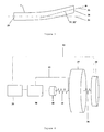
- Tube 1 is equivalent to a fixed flexible beam by one of its ends 29 to the turret 4. Its deformation can be characterized by the measurement of arcure 32.
- the arcure as shown in FIG. 3, is the angle that the axis 33 of the tube 1 at the level of the mouth 28 with the longitudinal axis 34 theoretical neutral of the tube 1 of the weapon.
- Tube 1 has some number of bending resonance frequencies due to its elasticity in flexion.
- the direction of a shot results directly from the orientation of the axis 33 of the tube 1 to level of the mouth 28 at the moment of the passage of the projectile when shooting. To maintain a quality level of accuracy of the shot, it is necessary to control or less to know the bending of the tube 1.
- the first (lowest) resonant frequency ⁇ n method or first resonance mode ⁇ n method can be at a relatively low frequency.
- the elasticity of the tube makes appear a first mode at a frequency of the order of 20 Hertz, close to the looping frequencies of the servocontrols.
- the ensuing resonance limits the possibilities and the quality of stabilization servos and consequently degrades the precision of the weapon and the shot. For good performance, the effects of this resonance should be kept to a minimum.
- This resonance frequency ⁇ n process has a high sensitivity to radial accelerations.
- the term "radial” means the directions orthogonal to the axis 34 of the weapon or longitudinal axis. These radial accelerations are mainly caused by the movements of the vehicle supporting the turret 4 and in particular its heave.
- This first bending mode ⁇ n process is also sensitive to the couples of the main motorization 2, 2 'pointing set up to guide the weapon in space or the torque and effort induced by the automatic firing in time.
- the model simplest equivalent is two masses inertial elements connected by a spring.
- the theoretical means simpler and more natural to cushion this type of system is to create a cushioning effect placed between the two masses.
- a solution can correspond to exert a radial, passive or ordered, in the belly area of the flexible mode to cushion, by leaning on a sleeve.
- This sleeve can to be an inert mass or anchor on the cradle of the weapon and leaning on the weapon at the knot secondary before the weapon.
- Such an effort, depending on the relative velocity between the belly and the sleeve would have the desired damping effect.
- the necessary support is difficult to achieve or its realization too binding on the architecture of the weapon.
- Figure 4 presents a diagram illustrating the model inertial equivalent of the weapon and turret 4 that you want to depreciate, as well as the command principle depreciation implemented.
- the weapon is represented by an equivalent inertia 35, connected to the turret 4 represented by an equivalent inertia 37, by a stiffness 36 representative of the elasticity in bending of the tube 1.
- the damping motor 6 ' causes the inertia 37 of the turret 4.
- a motor site 8 or 8 'deposit, of inertia 40 rotates the inertial load (turret and weapon or weapon alone) through a transmission site 9 or 9 'deposit, from stiffness 41.
- a first loop 12 slaves the motor 8 or 8 'in couple.
- the servo device 38 calculates the speed to be controlled at the motor 8 or 8 'depending on the speed at the output of the transmission 9 or 9 'provided by the measurement as a function of the target torque from the block upper level enslavement 39.
- a second servo loop 13 slaves the torque to apply to the tube depending on the speed arcuate 32 'measured at the mouth 28.
- the block servo-control 39 determines the damping torque in function of the deformation of tube 1 in known flexion by the arc speed 32 '.
- the servo loop 13 determines the torque of the amortization to be provided as a reference input to the servo loop torque 12. This couple is determined proportional to a magnitude indicative of the deformation. For this, we use information representative of the bending deformation of the the weapon: the arcure 32 or its derivative, the speed of arcure 32 '. This characteristic data can be either directly measured on the tube of the weapon in real time, be obtained by an "observer” drawn up in using the calculation model 21 of the weapon tube and its bending behavior when stressed.
- the real interest is to limit the sensitivity of the current to the vibrations of rolling, to a frequency domain immediately surrounding the resonance frequency, a strong attenuation appearing on both sides of this frequency.
- FIG. 5 shows, in logarithmic coordinates, the magnitude ratio (or ratio) between the intensity of the current sent to an electric motor and the mechanical torque that it can supply as a function of frequency (Hz) or pulsation (rd / s).
- This curve is represented by conventional convention to those skilled in the art, symbolized by its asymptotes.
- This curve clearly shows a threshold corresponding to the natural frequency ⁇ n engine of the engine. Below this threshold ⁇ n motor , the ratio is constant, the torque is proportional to the current. Above this threshold, the ratio increases with a slope of 12 dB / octave. The ratio therefore increases as the square of the frequency.
- the current required to obtain a given mechanical torque is proportional to this torque multiplied by the square of the frequency.
- the natural frequency ⁇ n indicative process of the considered method, here the tube of weapon is of the order of 20 Hz.
- ⁇ n engine of the motor inertia on the elasticity of the transmission is greater than three times the ⁇ n process of the process. This is difficult to achieve in practice.
- the energy cost of the control of a given torque is all the more important that the value of the natural frequency of the process ⁇ n process moves away from the value of the natural frequency ⁇ engine engine.
- FIG. 6 shows, in the same coordinate system, the effect on the same ratio between the current and the mechanical torque, of the setting of the natural frequency of the motorization ⁇ n motor on the natural frequency of the process ⁇ n process .
- This calibration also known as “tuning”, consists in modifying the parameters of the inertia of the engine and / or the stiffness of its transmission by choosing them such that the natural frequency ⁇ n motor of the inertia of the engine on the stiffness of the transmission, it is close to the natural frequency ⁇ n process of the considered method, in this case here the natural frequency ⁇ n method of first mode of the tube of the weapon 1.
- This curve clearly shows a minimum of the ratio to the the level of the natural resonance frequency of the tube 1 of the weapon 27.
- This minimum appears in the area of interest, since it is around this natural frequency that we seek the most to dampen the resonance ⁇ n process of the tube 1.
- This minimum may result in a lower ratio in a ratio N of the order of four, to the nominal ratio at the origin.
- We deduce the interest of such a calibration of the transmission on the energy cost of the damping control since we can obtain, in the area of interest, the same damping torque for a current N times less . This shows the importance of tuning the transmission to the natural frequency ⁇ n method of the tube 1.
- the device according to the invention allows to adopt for the damping of a weapon tube a motor 6, 6 'of a power up to 4 times lower than that necessary if the agreement of the transmission had not been realized.
- the gearbox of the main drive 2 or 2 ' has the particularity of being dimensioned to transmit the maximum sizing torque of the engine.
- experience shows that, on a heavy turret, for a torque requirement of acceleration of the order of 1 to 1.5 rd / s 2 , the elasticity of the motorization shows a natural frequency of the inertia of the engine on the elasticity of the transmission which is difficult to increase beyond 6 Hz.
- a second engine 6 (site) or 6 '(bearing), distinct from the first engine 2 or 2' can very advantageously be considered.
- One of the engines, for example, is responsible only for depreciation, while the other is dedicated to the score. It is thus possible to size more freely both engines according to its own constraints.
Landscapes
- Engineering & Computer Science (AREA)
- General Engineering & Computer Science (AREA)
- Physics & Mathematics (AREA)
- Acoustics & Sound (AREA)
- Aviation & Aerospace Engineering (AREA)
- Mechanical Engineering (AREA)
- Vibration Prevention Devices (AREA)
- Shafts, Cranks, Connecting Bars, And Related Bearings (AREA)
- Body Structure For Vehicles (AREA)
- Valve-Gear Or Valve Arrangements (AREA)
- Investigating Or Analyzing Materials By The Use Of Ultrasonic Waves (AREA)
- Supporting Of Heads In Record-Carrier Devices (AREA)
- Buildings Adapted To Withstand Abnormal External Influences (AREA)
Abstract
Description
- la figure 1 présente une vue de profil, d'une arme montée dans une tourelle,
- la figure 2 présente une vue de dessus, de cette même arme montée dans la tourelle,
- la figure 3 précise la définition de l'arcure,
- la figure 4 illustre la modélisation retenue pour le tube et le principe de la loi de commande utilisée pour amortir sa résonance,
- la figure 5 présente la courbe asymptotique du ratio entre le courant et le couple en fonction de la pulsation (fréquence),
- la figure 6 présente la même courbe dans le cas particulier d'un accord de la transmission.
- on dispose d'un système mécanique oscillant non amorti ou faiblement amorti,
- amortir ce système, ou limiter l'amplitude de résonance naturelle consiste à lui appliquer artificiellement un couple, en phase avec sa vitesse d'oscillation, proportionnel à cette vitesse et de sens opposé. Plus le coefficient de proportionnalité sera élevé, plus l'amplitude de la résonance diminuera.
Claims (7)
- Dispositif d'amortissement actif des oscillations d'une arme (27), à faible consommation énergétique, comprenant un tube (1) présentant une fréquence de résonance ωn procédé à amortir et mis en rotation autour d'un axe site (3) ou gisement (3') par un motoréducteur principal (2, 2'), par rapport à une tourelle (4) ou un bâti, caractérisé en ce qu'il comprend un motoréducteur secondaire (6, 6') comprenant un moteur (8, 8') et une transmission (9,9'), ledit motoréducteur secondaire (6, 6') appliquant en parallèle au motoréducteur principal (2, 2') un couple déterminé par une loi de commande (7, 7').
- Dispositif d'amortissement selon la revendication 1, caractérisé en ce que la fréquence de résonance ωn moteur de l'inertie du moteur (8, 8') sur l'élasticité de la transmission (9, 9') est proche de la fréquence de résonance ωn procédé du tube (1).
- Dispositif d'amortissement selon la revendication 1 ou 2, caractérisé en ce que la transmission (9, 9') du motoréducteur secondaire présente un jeu apparent vu du tube (1) inférieur à un centième de milliradian.
- Dispositif d'amortissement selon la revendication 3, caractérisé en ce que la loi de commande (7, 7') comprend une première boucle (12) asservissant le motoréducteur (6, 6') secondaire en couple.
- Dispositif d'amortissement selon la revendication 4, caractérisé en ce que la loi de commande (7, 7') comprend une seconde boucle (13) d'asservissement utilisant en entrée une vitesse d'arcure (32') du tube (1) mesurée par un capteur de vitesse d'arcure (20).
- Dispositif d'amortissement selon la revendication 4, caractérisé en ce que la loi de commande (7, 7') comprend une seconde boucle d'asservissement (13) utilisant en entrée une vitesse d'arcure (32') estimée par un modèle de comportement (21) du tube (1) en flexion.
- Dispositif d'amortissement selon la revendication 6, caractérisé en ce que le modèle de comportement (21) du tube en flexion estimant la vitesse d'arcure (32') comprend un gyromètre de masque (25) pour assurer le recalage du modèle d'estimation de la vitesse d'arcure.
Applications Claiming Priority (2)
| Application Number | Priority Date | Filing Date | Title |
|---|---|---|---|
| FR0308046 | 2003-07-02 | ||
| FR0308046A FR2857071B1 (fr) | 2003-07-02 | 2003-07-02 | Dispositif d'amortissement actif d'une arme par motorisation secondaire accordee |
Publications (2)
| Publication Number | Publication Date |
|---|---|
| EP1493985A1 true EP1493985A1 (fr) | 2005-01-05 |
| EP1493985B1 EP1493985B1 (fr) | 2006-10-25 |
Family
ID=33427675
Family Applications (1)
| Application Number | Title | Priority Date | Filing Date |
|---|---|---|---|
| EP04291597A Expired - Lifetime EP1493985B1 (fr) | 2003-07-02 | 2004-06-24 | Dispositif d'amortissement actif des oscillations d'une arme par motorisation secondaire accordée |
Country Status (4)
| Country | Link |
|---|---|
| EP (1) | EP1493985B1 (fr) |
| AT (1) | ATE343776T1 (fr) |
| DE (1) | DE602004002901T2 (fr) |
| FR (1) | FR2857071B1 (fr) |
Families Citing this family (2)
| Publication number | Priority date | Publication date | Assignee | Title |
|---|---|---|---|---|
| DE102007046545B4 (de) | 2007-09-27 | 2011-12-29 | Rheinmetall Waffe Munition Gmbh | Verfahren und Vorrichtung zur Steuerung der Schussfolge einer Maschinenwaffe |
| DE102012001534B4 (de) * | 2012-01-27 | 2014-06-26 | Rheinmetall Landsysteme Gmbh | Entkoppelungssystem für Antriebe bei Tumsystemen |
Citations (3)
| Publication number | Priority date | Publication date | Assignee | Title |
|---|---|---|---|---|
| DE2240569B1 (de) * | 1972-08-18 | 1974-01-03 | Honeywell Gmbh, 6000 Frankfurt | Antriebsvorrichtung fuer zu stabilisierende plattformen oder geraete |
| FR2192665A5 (fr) * | 1972-07-07 | 1974-02-08 | France Etat | |
| DE2605476A1 (de) * | 1976-02-12 | 1977-08-18 | Johann Prof Dr I Kleinwaechter | Aktive schwingungsdaempfung elastischer antriebselemente |
-
2003
- 2003-07-02 FR FR0308046A patent/FR2857071B1/fr not_active Expired - Fee Related
-
2004
- 2004-06-24 EP EP04291597A patent/EP1493985B1/fr not_active Expired - Lifetime
- 2004-06-24 DE DE602004002901T patent/DE602004002901T2/de not_active Expired - Lifetime
- 2004-06-24 AT AT04291597T patent/ATE343776T1/de not_active IP Right Cessation
Patent Citations (3)
| Publication number | Priority date | Publication date | Assignee | Title |
|---|---|---|---|---|
| FR2192665A5 (fr) * | 1972-07-07 | 1974-02-08 | France Etat | |
| DE2240569B1 (de) * | 1972-08-18 | 1974-01-03 | Honeywell Gmbh, 6000 Frankfurt | Antriebsvorrichtung fuer zu stabilisierende plattformen oder geraete |
| DE2605476A1 (de) * | 1976-02-12 | 1977-08-18 | Johann Prof Dr I Kleinwaechter | Aktive schwingungsdaempfung elastischer antriebselemente |
Also Published As
| Publication number | Publication date |
|---|---|
| ATE343776T1 (de) | 2006-11-15 |
| EP1493985B1 (fr) | 2006-10-25 |
| DE602004002901T2 (de) | 2007-04-05 |
| FR2857071A1 (fr) | 2005-01-07 |
| FR2857071B1 (fr) | 2005-09-30 |
| DE602004002901D1 (de) | 2006-12-07 |
Similar Documents
| Publication | Publication Date | Title |
|---|---|---|
| FR2861357A1 (fr) | Systeme de commande de vibrations pour systeme de direction a inclinaison electrique | |
| EP1255673A1 (fr) | Engin volant telecommande, en particulier de surveillance ou d'inspection | |
| FR2934246A1 (fr) | Aeronef comprenant au moins un moteur a rotors contrarotatifs | |
| EP0199648B1 (fr) | Procédé et dispositif d'amortissement de nutation de satellite par commande d'orientation de masses présentant un produit d'inertie variable | |
| FR2756945A1 (fr) | Navigation solaire multiaxiale | |
| FR2550390A1 (fr) | Monture d'antenne a stabilisation passive | |
| EP1493985B1 (fr) | Dispositif d'amortissement actif des oscillations d'une arme par motorisation secondaire accordée | |
| EP1409947B1 (fr) | Systeme de pointage en site et en gisement d'une arme | |
| EP1493942A1 (fr) | Dispositif d'amortissement actif d'une arme par accord de la transmission | |
| EP1570326B1 (fr) | Procede et dispositif de pilotage d'un engin orientable au moyen d'un actionneur asservi en attitude sur une trajectoire | |
| CN120406091A (zh) | 一种基于微机械陀螺的稳定平台抗冲击方法及装置 | |
| EP1395789B1 (fr) | Systeme de pointage d'une arme | |
| FR2907616A1 (fr) | Tourelle d'orientation deux axes avec motorisation piezo electrique | |
| FR2459443A1 (fr) | Procede et dispositif de determination des elements de tir d'un projectile | |
| EP4217790B1 (fr) | Asservissement adaptatif d'un viseur optronique | |
| FR2492965A1 (fr) | Dispositif de reduction de la dispersion du tir d'une arme | |
| EP3929522B1 (fr) | Dispositif de pointage pour un système d'arme comprenant une arme solidaire d'un châssis et procédé mettant en oeuvre un tel dispositif | |
| EP1422587A1 (fr) | Procédé d'élaboration d'un ordre de commande pour un organe permettant le pilotage d'un projectile girant | |
| EP4174435B1 (fr) | Système de visée et de défense comprenant un tourelleau et un système laser et véhicule automobile comprenant un tel système de visée et de défense | |
| FR3130023A1 (fr) | Asservissement adaptatif d’un viseur optronique | |
| FR2666561A1 (fr) | Procede de pilotage d'un engin spatial dote d'un mouvement de precession et dispositif pour sa mise en óoeuvre. | |
| EP2397882B1 (fr) | Dispositif de balayage rapide double étage pour système d'observation à distance | |
| EP3317604B1 (fr) | Procédé et dispositif motorisé de pointage | |
| EP2668100B1 (fr) | Procédé et système de pilotage d'un engin volant à propulseur arrière | |
| FR2504703A1 (fr) | Systeme d'asservissement d'un projectile a une reference axiale pour supprimer l'effet du vent |
Legal Events
| Date | Code | Title | Description |
|---|---|---|---|
| PUAI | Public reference made under article 153(3) epc to a published international application that has entered the european phase |
Free format text: ORIGINAL CODE: 0009012 |
|
| AK | Designated contracting states |
Kind code of ref document: A1 Designated state(s): AT BE BG CH CY CZ DE DK EE ES FI FR GB GR HU IE IT LI LU MC NL PL PT RO SE SI SK TR |
|
| AX | Request for extension of the european patent |
Extension state: AL HR LT LV MK |
|
| 17P | Request for examination filed |
Effective date: 20050613 |
|
| AKX | Designation fees paid |
Designated state(s): AT BE BG CH CY CZ DE DK EE ES FI FR GB GR HU IE IT LI LU MC NL PL PT RO SE SI SK TR |
|
| GRAP | Despatch of communication of intention to grant a patent |
Free format text: ORIGINAL CODE: EPIDOSNIGR1 |
|
| GRAS | Grant fee paid |
Free format text: ORIGINAL CODE: EPIDOSNIGR3 |
|
| GRAA | (expected) grant |
Free format text: ORIGINAL CODE: 0009210 |
|
| AK | Designated contracting states |
Kind code of ref document: B1 Designated state(s): AT BE BG CH CY CZ DE DK EE ES FI FR GB GR HU IE IT LI LU MC NL PL PT RO SE SI SK TR |
|
| PG25 | Lapsed in a contracting state [announced via postgrant information from national office to epo] |
Ref country code: PL Free format text: LAPSE BECAUSE OF FAILURE TO SUBMIT A TRANSLATION OF THE DESCRIPTION OR TO PAY THE FEE WITHIN THE PRESCRIBED TIME-LIMIT Effective date: 20061025 Ref country code: FI Free format text: LAPSE BECAUSE OF FAILURE TO SUBMIT A TRANSLATION OF THE DESCRIPTION OR TO PAY THE FEE WITHIN THE PRESCRIBED TIME-LIMIT Effective date: 20061025 Ref country code: RO Free format text: LAPSE BECAUSE OF FAILURE TO SUBMIT A TRANSLATION OF THE DESCRIPTION OR TO PAY THE FEE WITHIN THE PRESCRIBED TIME-LIMIT Effective date: 20061025 Ref country code: NL Free format text: LAPSE BECAUSE OF FAILURE TO SUBMIT A TRANSLATION OF THE DESCRIPTION OR TO PAY THE FEE WITHIN THE PRESCRIBED TIME-LIMIT Effective date: 20061025 Ref country code: AT Free format text: LAPSE BECAUSE OF FAILURE TO SUBMIT A TRANSLATION OF THE DESCRIPTION OR TO PAY THE FEE WITHIN THE PRESCRIBED TIME-LIMIT Effective date: 20061025 Ref country code: SI Free format text: LAPSE BECAUSE OF FAILURE TO SUBMIT A TRANSLATION OF THE DESCRIPTION OR TO PAY THE FEE WITHIN THE PRESCRIBED TIME-LIMIT Effective date: 20061025 Ref country code: CZ Free format text: LAPSE BECAUSE OF FAILURE TO SUBMIT A TRANSLATION OF THE DESCRIPTION OR TO PAY THE FEE WITHIN THE PRESCRIBED TIME-LIMIT Effective date: 20061025 Ref country code: IE Free format text: LAPSE BECAUSE OF FAILURE TO SUBMIT A TRANSLATION OF THE DESCRIPTION OR TO PAY THE FEE WITHIN THE PRESCRIBED TIME-LIMIT Effective date: 20061025 Ref country code: SK Free format text: LAPSE BECAUSE OF FAILURE TO SUBMIT A TRANSLATION OF THE DESCRIPTION OR TO PAY THE FEE WITHIN THE PRESCRIBED TIME-LIMIT Effective date: 20061025 |
|
| REG | Reference to a national code |
Ref country code: GB Ref legal event code: FG4D Free format text: NOT ENGLISH |
|
| REG | Reference to a national code |
Ref country code: CH Ref legal event code: EP |
|
| REG | Reference to a national code |
Ref country code: IE Ref legal event code: FG4D Free format text: LANGUAGE OF EP DOCUMENT: FRENCH |
|
| REF | Corresponds to: |
Ref document number: 602004002901 Country of ref document: DE Date of ref document: 20061207 Kind code of ref document: P |
|
| GBT | Gb: translation of ep patent filed (gb section 77(6)(a)/1977) |
Effective date: 20061207 |
|
| PG25 | Lapsed in a contracting state [announced via postgrant information from national office to epo] |
Ref country code: SE Free format text: LAPSE BECAUSE OF FAILURE TO SUBMIT A TRANSLATION OF THE DESCRIPTION OR TO PAY THE FEE WITHIN THE PRESCRIBED TIME-LIMIT Effective date: 20070125 Ref country code: BG Free format text: LAPSE BECAUSE OF FAILURE TO SUBMIT A TRANSLATION OF THE DESCRIPTION OR TO PAY THE FEE WITHIN THE PRESCRIBED TIME-LIMIT Effective date: 20070125 Ref country code: DK Free format text: LAPSE BECAUSE OF FAILURE TO SUBMIT A TRANSLATION OF THE DESCRIPTION OR TO PAY THE FEE WITHIN THE PRESCRIBED TIME-LIMIT Effective date: 20070125 |
|
| PG25 | Lapsed in a contracting state [announced via postgrant information from national office to epo] |
Ref country code: ES Free format text: LAPSE BECAUSE OF FAILURE TO SUBMIT A TRANSLATION OF THE DESCRIPTION OR TO PAY THE FEE WITHIN THE PRESCRIBED TIME-LIMIT Effective date: 20070205 |
|
| PG25 | Lapsed in a contracting state [announced via postgrant information from national office to epo] |
Ref country code: PT Free format text: LAPSE BECAUSE OF FAILURE TO SUBMIT A TRANSLATION OF THE DESCRIPTION OR TO PAY THE FEE WITHIN THE PRESCRIBED TIME-LIMIT Effective date: 20070326 |
|
| NLV1 | Nl: lapsed or annulled due to failure to fulfill the requirements of art. 29p and 29m of the patents act | ||
| REG | Reference to a national code |
Ref country code: IE Ref legal event code: FD4D |
|
| PLBE | No opposition filed within time limit |
Free format text: ORIGINAL CODE: 0009261 |
|
| STAA | Information on the status of an ep patent application or granted ep patent |
Free format text: STATUS: NO OPPOSITION FILED WITHIN TIME LIMIT |
|
| 26N | No opposition filed |
Effective date: 20070726 |
|
| BERE | Be: lapsed |
Owner name: GIAT INDUSTRIES Effective date: 20070630 |
|
| PG25 | Lapsed in a contracting state [announced via postgrant information from national office to epo] |
Ref country code: MC Free format text: LAPSE BECAUSE OF NON-PAYMENT OF DUE FEES Effective date: 20070630 |
|
| PG25 | Lapsed in a contracting state [announced via postgrant information from national office to epo] |
Ref country code: BE Free format text: LAPSE BECAUSE OF NON-PAYMENT OF DUE FEES Effective date: 20070630 |
|
| PG25 | Lapsed in a contracting state [announced via postgrant information from national office to epo] |
Ref country code: GR Free format text: LAPSE BECAUSE OF FAILURE TO SUBMIT A TRANSLATION OF THE DESCRIPTION OR TO PAY THE FEE WITHIN THE PRESCRIBED TIME-LIMIT Effective date: 20070126 |
|
| PG25 | Lapsed in a contracting state [announced via postgrant information from national office to epo] |
Ref country code: EE Free format text: LAPSE BECAUSE OF FAILURE TO SUBMIT A TRANSLATION OF THE DESCRIPTION OR TO PAY THE FEE WITHIN THE PRESCRIBED TIME-LIMIT Effective date: 20061025 |
|
| REG | Reference to a national code |
Ref country code: CH Ref legal event code: PL |
|
| PG25 | Lapsed in a contracting state [announced via postgrant information from national office to epo] |
Ref country code: CH Free format text: LAPSE BECAUSE OF NON-PAYMENT OF DUE FEES Effective date: 20080630 Ref country code: LI Free format text: LAPSE BECAUSE OF NON-PAYMENT OF DUE FEES Effective date: 20080630 |
|
| REG | Reference to a national code |
Ref country code: GB Ref legal event code: 732E Free format text: REGISTERED BETWEEN 20090625 AND 20090701 |
|
| PG25 | Lapsed in a contracting state [announced via postgrant information from national office to epo] |
Ref country code: CY Free format text: LAPSE BECAUSE OF FAILURE TO SUBMIT A TRANSLATION OF THE DESCRIPTION OR TO PAY THE FEE WITHIN THE PRESCRIBED TIME-LIMIT Effective date: 20061025 Ref country code: LU Free format text: LAPSE BECAUSE OF NON-PAYMENT OF DUE FEES Effective date: 20070624 |
|
| PG25 | Lapsed in a contracting state [announced via postgrant information from national office to epo] |
Ref country code: HU Free format text: LAPSE BECAUSE OF FAILURE TO SUBMIT A TRANSLATION OF THE DESCRIPTION OR TO PAY THE FEE WITHIN THE PRESCRIBED TIME-LIMIT Effective date: 20070426 Ref country code: TR Free format text: LAPSE BECAUSE OF FAILURE TO SUBMIT A TRANSLATION OF THE DESCRIPTION OR TO PAY THE FEE WITHIN THE PRESCRIBED TIME-LIMIT Effective date: 20061025 |
|
| PGFP | Annual fee paid to national office [announced via postgrant information from national office to epo] |
Ref country code: IT Payment date: 20070630 Year of fee payment: 4 |
|
| PGFP | Annual fee paid to national office [announced via postgrant information from national office to epo] |
Ref country code: GB Payment date: 20150527 Year of fee payment: 12 |
|
| REG | Reference to a national code |
Ref country code: FR Ref legal event code: PLFP Year of fee payment: 13 |
|
| GBPC | Gb: european patent ceased through non-payment of renewal fee |
Effective date: 20160624 |
|
| REG | Reference to a national code |
Ref country code: FR Ref legal event code: PLFP Year of fee payment: 14 |
|
| PG25 | Lapsed in a contracting state [announced via postgrant information from national office to epo] |
Ref country code: GB Free format text: LAPSE BECAUSE OF NON-PAYMENT OF DUE FEES Effective date: 20160624 |
|
| REG | Reference to a national code |
Ref country code: FR Ref legal event code: PLFP Year of fee payment: 15 |
|
| PGFP | Annual fee paid to national office [announced via postgrant information from national office to epo] |
Ref country code: FR Payment date: 20230524 Year of fee payment: 20 Ref country code: DE Payment date: 20230523 Year of fee payment: 20 |
|
| REG | Reference to a national code |
Ref country code: DE Ref legal event code: R071 Ref document number: 602004002901 Country of ref document: DE |