EP1493984A1 - Surface treatment method for plate material, and radiating fin for heat exchanger - Google Patents
Surface treatment method for plate material, and radiating fin for heat exchanger Download PDFInfo
- Publication number
- EP1493984A1 EP1493984A1 EP03712872A EP03712872A EP1493984A1 EP 1493984 A1 EP1493984 A1 EP 1493984A1 EP 03712872 A EP03712872 A EP 03712872A EP 03712872 A EP03712872 A EP 03712872A EP 1493984 A1 EP1493984 A1 EP 1493984A1
- Authority
- EP
- European Patent Office
- Prior art keywords
- plate material
- coating
- heat exchanger
- cooling fin
- treating
- Prior art date
- Legal status (The legal status is an assumption and is not a legal conclusion. Google has not performed a legal analysis and makes no representation as to the accuracy of the status listed.)
- Withdrawn
Links
Images

Classifications
-
- F—MECHANICAL ENGINEERING; LIGHTING; HEATING; WEAPONS; BLASTING
- F28—HEAT EXCHANGE IN GENERAL
- F28F—DETAILS OF HEAT-EXCHANGE AND HEAT-TRANSFER APPARATUS, OF GENERAL APPLICATION
- F28F19/00—Preventing the formation of deposits or corrosion, e.g. by using filters or scrapers
- F28F19/02—Preventing the formation of deposits or corrosion, e.g. by using filters or scrapers by using coatings, e.g. vitreous or enamel coatings
- F28F19/04—Preventing the formation of deposits or corrosion, e.g. by using filters or scrapers by using coatings, e.g. vitreous or enamel coatings of rubber; of plastics material; of varnish
-
- B—PERFORMING OPERATIONS; TRANSPORTING
- B05—SPRAYING OR ATOMISING IN GENERAL; APPLYING FLUENT MATERIALS TO SURFACES, IN GENERAL
- B05D—PROCESSES FOR APPLYING FLUENT MATERIALS TO SURFACES, IN GENERAL
- B05D7/00—Processes, other than flocking, specially adapted for applying liquids or other fluent materials to particular surfaces or for applying particular liquids or other fluent materials
- B05D7/14—Processes, other than flocking, specially adapted for applying liquids or other fluent materials to particular surfaces or for applying particular liquids or other fluent materials to metal, e.g. car bodies
- B05D7/16—Processes, other than flocking, specially adapted for applying liquids or other fluent materials to particular surfaces or for applying particular liquids or other fluent materials to metal, e.g. car bodies using synthetic lacquers or varnishes
-
- F—MECHANICAL ENGINEERING; LIGHTING; HEATING; WEAPONS; BLASTING
- F28—HEAT EXCHANGE IN GENERAL
- F28F—DETAILS OF HEAT-EXCHANGE AND HEAT-TRANSFER APPARATUS, OF GENERAL APPLICATION
- F28F1/00—Tubular elements; Assemblies of tubular elements
- F28F1/10—Tubular elements and assemblies thereof with means for increasing heat-transfer area, e.g. with fins, with projections, with recesses
- F28F1/12—Tubular elements and assemblies thereof with means for increasing heat-transfer area, e.g. with fins, with projections, with recesses the means being only outside the tubular element
- F28F1/24—Tubular elements and assemblies thereof with means for increasing heat-transfer area, e.g. with fins, with projections, with recesses the means being only outside the tubular element and extending transversely
- F28F1/32—Tubular elements and assemblies thereof with means for increasing heat-transfer area, e.g. with fins, with projections, with recesses the means being only outside the tubular element and extending transversely the means having portions engaging further tubular elements
-
- F—MECHANICAL ENGINEERING; LIGHTING; HEATING; WEAPONS; BLASTING
- F28—HEAT EXCHANGE IN GENERAL
- F28F—DETAILS OF HEAT-EXCHANGE AND HEAT-TRANSFER APPARATUS, OF GENERAL APPLICATION
- F28F13/00—Arrangements for modifying heat-transfer, e.g. increasing, decreasing
- F28F13/18—Arrangements for modifying heat-transfer, e.g. increasing, decreasing by applying coatings, e.g. radiation-absorbing, radiation-reflecting; by surface treatment, e.g. polishing
-
- B—PERFORMING OPERATIONS; TRANSPORTING
- B05—SPRAYING OR ATOMISING IN GENERAL; APPLYING FLUENT MATERIALS TO SURFACES, IN GENERAL
- B05D—PROCESSES FOR APPLYING FLUENT MATERIALS TO SURFACES, IN GENERAL
- B05D2252/00—Sheets
- B05D2252/02—Sheets of indefinite length
-
- B—PERFORMING OPERATIONS; TRANSPORTING
- B05—SPRAYING OR ATOMISING IN GENERAL; APPLYING FLUENT MATERIALS TO SURFACES, IN GENERAL
- B05D—PROCESSES FOR APPLYING FLUENT MATERIALS TO SURFACES, IN GENERAL
- B05D2701/00—Coatings being able to withstand changes in the shape of the substrate or to withstand welding
- B05D2701/20—Coatings being able to withstand changes in the shape of the substrate or to withstand welding withstanding rolling
-
- B—PERFORMING OPERATIONS; TRANSPORTING
- B05—SPRAYING OR ATOMISING IN GENERAL; APPLYING FLUENT MATERIALS TO SURFACES, IN GENERAL
- B05D—PROCESSES FOR APPLYING FLUENT MATERIALS TO SURFACES, IN GENERAL
- B05D7/00—Processes, other than flocking, specially adapted for applying liquids or other fluent materials to particular surfaces or for applying particular liquids or other fluent materials
- B05D7/14—Processes, other than flocking, specially adapted for applying liquids or other fluent materials to particular surfaces or for applying particular liquids or other fluent materials to metal, e.g. car bodies
-
- B—PERFORMING OPERATIONS; TRANSPORTING
- B21—MECHANICAL METAL-WORKING WITHOUT ESSENTIALLY REMOVING MATERIAL; PUNCHING METAL
- B21B—ROLLING OF METAL
- B21B45/00—Devices for surface or other treatment of work, specially combined with or arranged in, or specially adapted for use in connection with, metal-rolling mills
- B21B45/02—Devices for surface or other treatment of work, specially combined with or arranged in, or specially adapted for use in connection with, metal-rolling mills for lubricating, cooling, or cleaning
- B21B45/0239—Lubricating
- B21B45/0245—Lubricating devices
- B21B45/0248—Lubricating devices using liquid lubricants, e.g. for sections, for tubes
- B21B45/0251—Lubricating devices using liquid lubricants, e.g. for sections, for tubes for strips, sheets, or plates
-
- F—MECHANICAL ENGINEERING; LIGHTING; HEATING; WEAPONS; BLASTING
- F28—HEAT EXCHANGE IN GENERAL
- F28F—DETAILS OF HEAT-EXCHANGE AND HEAT-TRANSFER APPARATUS, OF GENERAL APPLICATION
- F28F2245/00—Coatings; Surface treatments
- F28F2245/02—Coatings; Surface treatments hydrophilic
Definitions
- the present invention relates to a method of treating the surface of a plate material, and more specifically relates to a method of treating the surface of a plate material in which the plate material is rolled with rolling oil, the plate material being employed as cooling fins for heat exchangers.
- the present invention relates to cooling fins for heat exchangers, and in particular relates to plate-shaped fins disposed inside a heat exchanger formed from a plate material that is rolled with rolling oil.
- the outdoor unit and indoor unit of an air conditioner each generally include a heat exchanger for exchanging heat between the heat exchanger and the air surrounding it.
- a heat exchanger normally includes a plurality of cooling fins, a plurality of heat transfer lines, and air transport means such as a propeller fan or the like.
- the plurality of cooling fins are plate-shaped members that are disposed with a predetermined gap between each member in the plate thickness direction.
- the plurality of heat transfer lines are mounted such that they pass through the plurality of cooling fins in the plate thickness direction.
- the air transport means serves to transport an air flow to the plurality of cooling fins and heat transfer lines.
- heat exchange occurs by transporting an air flow with the air transport means through the gaps between adjacent cooling fins, and evaporating or condensing refrigerant that flows inside the heat transfer lines.
- the cooling fins are generally composed of a pure aluminum plate material, and the plate material is manufactured by cutting the plate material into predetermined fin shapes by means of a metal die. Before the plate material is cut, a corrosion resistant coating is applied to the plate material to form a corrosion resistant film that will improve the corrosion resistance of the plate material.
- the plate material is dipped in a tank of alkaline solution in order to degrease the plate material, and is then dipped in a tank of a chromic acid processing agent in order to both form the corrosion resistant film on the surface thereof and roughen the surface thereof.
- the treatment waste fluid produced by the chromic acid process includes heavy metals and is a problem from an environmental point of view, it will be necessary to dispose of the treatment waste fluid after a predetermined number of treatments.
- the running cost thereof is quite expensive because specialized waste fluid tanks must be treated differently, and because the waste fluid must be processed at fixed intervals of time.
- An object of the present invention is to reduce the expense of treating the surfaces of plate material.
- another object of the present invention is to carry out this type of surface treatment to obtain cooling fins for heat exchangers.
- a surface treatment method is a method for treating the surface of a plate material that is rolled with rolling oil and employed as cooling fins for heat exchangers, the method including a first step and a second step.
- the plate material is prepared.
- a coating is applied to the surfaces of the plate material without carrying out a degreasing treatment.
- a coating can be applied to a plate material without performing a degreasing treatment, and thus a conventional degreasing treatment tank will not be necessary and costs will be reduced.
- the surface treatment method according to claim 2 is the surface treatment method of claim 1, in which in the second step the coating is applied to the surface of the plate material without carrying out a surface roughing treatment.
- a coating can be applied to a plate material without performing a surface roughing treatment, and thus a conventional chromic acid treatment tank will not be necessary and costs will be reduced. In addition, running costs can be avoided because waste fluid treatment need not be performed.
- the surface treatment method according to claim 3 is the surface treatment method of claim 1 or 2, in which in the second step the coating is applied to the surface of the plate material by transporting the plate material at a speed of 50 m/min or less.
- the coating having a high viscosity and not easily repelled by oil can be employed because the coating is applied to the plate material at a comparatively slow speed.
- a degreasing treatment can be omitted.
- a surface treatment method according to claim 4 is the surface treatment method of claim 3, in which the coating has a viscosity that is related to the application speed at which the coating is applied to the plate material.
- the viscosity of the coating that can be used at that application speed will also change.
- the viscosity of the coating that can be used is related to the speed at which the coating is applied.
- a surface treatment method according to claim 5 is the surface treatment method of any of claims 1 to 4, in which in the second step the coating is dried in atmospheric air at a temperature between 240°C and 270°C.
- a surface treatment method is the surface treatment method of any of claims 1 to 5, in which the coating includes a corrosion resistant coating and a hydrophilic coating.
- the second step includes a third step and a fourth step.
- the corrosion resistant coating is applied to the surface of the plate material.
- the hydrophilic coating is applied to the surface of the plate material after the third step.
- cooling fins When the cooling fins are, for example, employed in a heat exchanger of an indoor unit, they will be required to have hydrophilic properties in addition to a resistance to corrosion. In this situation, after a corrosion resistant film is formed on the surface of the plate material, a hydrophilic film will be formed on top of the corrosion resistant film.
- this method is primarily directed at a surface treatment for a plate materials employed as cooling fins in an heat exchanger for an outdoor unit.
- a surface treatment method according to claim 7 is the surface treatment method of any of claims 1 to 6, in which in the fourth step the plate material is transported in a transport path that is the same as the transport path of the third step but in a direction that is opposite to that of the third step.
- the plate material is normally transported at a predetermined speed and coatings are applied thereto and dried.
- both the corrosion resistant coating and the hydrophilic coating are applied in the same path, and thus both drying steps can be performed by arranging, for example, only one drying oven in the transport path. Because of this, costs can be further reduced, and work efficiency can be improved.
- the surface treatment method according to claim 8 is the surface treatment method of claim 7, in which in the third step the coating is applied to the plate material in atmospheric air that is at a temperature that is lower than that of the fourth step.
- the corrosion resistant coating is applied at a temperature that is lower than the temperature at which the hydrophilic coating is applied, and thus the production of heat history in the corrosion resistant coating can be avoided when the hydrophilic coating is dried.
- a cooling fin for a heat exchanger is composed of a plate material that was rolled with a rolling oil, and having a plate shape for radiating heat that is disposed inside the heat exchanger.
- the cooling fin includes a fin unit and a coating film.
- the coating film is formed on the surfaces of the fin unit. 10 mg or less of the rolling oil are included per 1 m 2 of the surface of the fin unit.
- the cooling fins have a predetermined amount of rolling oil remaining thereon, which can confirm that the surface treatment did not include a degreasing treatment.
- a cooling fin for a heat exchanger is composed of a plate material that was rolled with a rolling oil, and having a plate shape for radiating heat that is disposed inside the heat exchanger.
- the cooling fin includes a fin unit and a coating film.
- the coating film is formed on the surfaces of the fin unit. And, the coating film has a peak in the infrared spectrum that corresponds to the primary constituent of the rolling oil.
- the cooling fin has a portion of the rolling oil remaining thereon in the dissolved state, and thus when the infrared spectrum of the coating film is measured, a peak that corresponds to the primary constituent of the rolling oil will appear. Thus, it can be confirmed that the surface of the cooling fin was treated without a degreasing treatment.
- a cooling fin for a heat exchanger according to claim 11 is the cooling fin for a heat exchanger of claim 10, in which the coating film has a peak in the infrared spectrum in a range between 1500 cm -1 and 2000 cm -1 .
- a cooling fin having a coating film with a peak in the infrared spectrum in this range is sought because there are many commonly used rolling oils that have a peak in this range.
- This cooling fin has a portion of the rolling oil remaining thereon in the dissolved state, and thus when the infrared spectrum of the coating film is measured, a peak that corresponds to the primary constituent of the rolling oil will appear. Thus, it can be confirmed that the surface of the cooling fin was treated without a degreasing treatment.
- a cooling fin for a heat exchanger according to claim 12 is the cooling fin for a heat exchanger of any of claims 9 to 11, in which there are concave and convex portions on the surface of the coating film in a range between 2 and 5 micrometers in the plate thickness direction.
- the cooling fin has not had a surface roughing treatment carried out on it, and thus the concave and convex portions on the surface of the coating film are smaller than those produced by a surface roughing treatment, and the convex and concave portions are maintained within the aforementioned range. Thus, it can be confirmed that the surface of the cooling fin was treated without a surface roughing treatment.
- a cooling fin for a heat exchanger according to claim 13 employs a plate material treated by means of a surface treatment method disclosed in any of claims 1 to 8.
- This cooling fin is manufactured by employing a plate material treated by the aforementioned surface treatment method, and was manufactured via a treatment process that reduces the cost of equipment or the like for surface treatment.
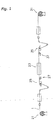
- Fig. 1 shows a summary of a surface treatment method according to an embodiment of the present invention.
- a plate material 1 is set such that it extends between two coilers 21, 31.
- the coilers 21, 31 are devices which can respectively unroll and wind up the plate material 1, and the plate material 1 can be transported to either left or right in Fig. 1 by either unrolling the plate material 1 or by winding up the plate material 1.
- a drying oven 23 is disposed approximately midway between the two coilers 21, 31, and serves to dry a coating applied to the surfaces of the plate material 1.
- the drying oven 23 is open in the direction in which the plate material 1 is transported, and the plate material 1 is movably disposed inside the drying oven 23.
- a roll coater 25 for applying a corrosion resistant coating (described below) is disposed on the coiler 21 side of the drying oven 23, and a roll coater 35 for applying a hydrophilic coating (described below) is disposed on the coiler 31 side of the drying oven 23.
- the roll surface of the roll coater 25 is mesh finished in order to increase the retentivity of the coating, and the roll surface of the roll coater 35 is dull-finished.
- processing units 27, 37 for affixing a processing agent to the surface of the coating are respectively disposed on the downstream side in the transport direction of the roll coaters 25, 35, and cooling blowers 29, 39 for cooling the plate material 1 heated by the drying oven 23 are disposed further downstream from the drying oven 23.
- This method serves to treat the surface of a plate material 1 that was rolled with rolling oil.
- the plate material 1 is employed primarily for cooling fins that are disposed inside heat exchangers for the indoor and outdoor units of an air conditioner.
- This method includes a preparation step and a coating application step.
- a plate material 1 that is wound into a roll is prepared, and set onto the coilers 21, 31.
- the plate material 1 is made from pure aluminum, and is manufactured by rolling with a rolling oil.
- a coating is applied to the surfaces of the plate material 1 without carrying out a degreasing treatment and a surface roughing treatment.
- This step includes a corrosion resistant coating application step and a hydrophilic coating application step.
- a corrosion resistant coating is applied to the surfaces of the plate material 1 by means of the roll coater 25.
- the coating is applied at a fixed speed by means of the roll coater 25 by transporting the plate material 1 to the right in Fig. 1 at a fixed speed.
- the coating is applied at a speed of 50 m/min or less, and preferably at a speed of 10 to 40 m/min.
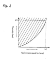
- the viscosity of the coating that can be employed here is related to the speed at which the coating is applied to the plate material 1. More specifically, a coating is used which has a viscosity in a range represented by the diagonal lines in Fig. 2. Note that when the application speed is high, a coating with a low viscosity cannot be used in the present method. This is because when the viscosity is low, the coating cannot be satisfactorily retained on the rollers of the roll coater 25, and thus cannot be satisfactorily applied to the plate material 1. Thus, for example, when the application speed is 50 m/min, it is preferable to use a coating having a viscosity of 40 sec or higher. Note that in conventional surface treatments, the coating is applied at a speed of between 100 and 250 m/min.
- the plate material 1 is transported to the drying oven 23, and dried in atmospheric air at a temperature between 240 and 270°C.
- the plate material 1 is dried at a temperature that is lower than the drying temperature used in the subsequent hydrophilic coating application step.
- a hydrophilic coating is applied to the surfaces of the plate material 1 by means of the roll coater 35.
- the coating is applied at a fixed speed by transporting the plate material 1 to the left in Fig. 1 at a fixed speed.
- the application speed is identical to that at which the corrosion resistant coating was applied.
- An acrylic resin coating is employed as the hydrophilic coating.
- the viscosity of the hydrophilic coating that can be employed here is related to the application speed in the same way as that of the corrosion resistant coating.
- the hydrophilic coating is dried in the same atmospheric air where the corrosion resistant coating was dried, however as noted above, the temperature at which the hydrophilic coating is dried is higher than the temperature at which the corrosion resistant coating is dried.
- the plate material 1 is first transported from the coiler 21 toward the coiler 31.
- the plate material 1 has a corrosion resistant coating applied thereto by means of the roll coater 25 without carrying out a degreasing treatment and a chromic acid treatment.
- a processing agent is affixed to the plate material 1 by the processing unit 27, the plate material 1 is heated up to the aforementioned predetermined temperature inside the drying oven 23, and the coating is dried and hardened.
- the plate material 1 is cooled by the cooling blower 29 and wound by the coiler 31.
- the plate material 1 is transported from the coiler 31 toward the coiler 21, while the hydrophilic coating is applied by the roll coater 35. Then, after a processing agent is affixed to the plate material 1 by the processing unit 37, the plate material 1 is heated up to the aforementioned predetermined temperature inside the drying oven 23, and the coating is dried and hardened. After that, the plate material 1 is cooled by the cooling blower 39 and wound by the coiler 21.
- the coating is applied to the plate material 1 at a speed that is comparatively slower than the conventional speed, and thus a coating having a comparatively high viscosity can be employed. Because of this, even if rolling oil remains on the plate material 1, a coating can be prevented from being repelled by the rolling oil and a coating film can be formed. Then, by applying this method, a conventional degreasing treatment and surface roughing treatment can be omitted, and thus a treatment layer for each treatment will not be necessary and costs will be greatly reduced.
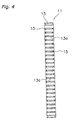
- Figs. 3 and 4 show a cooling fin 11 for a heat exchanger which is employed in an embodiment of the present invention.
- the cooling fin 11 is a plate-shaped fin for radiating heat that is disposed inside a heat exchanger.
- the cooling fin 11 is composed of the plate material 1 that has been treated by means of the aforementioned surface treatment method, and includes a fin unit 13 and a coating film 15.
- the fin unit 13 is manufactured by cutting the plate material 1 into a predetermined fin shape by means of a metal die, and forming it into the shape shown in the figures.
- the fin unit 13 includes a plurality of holes 13a in which a plurality of heat transfer lines (not shown in the figures) that are disposed inside the heat exchanger pass through the holes 13a.
- the coating film 15 is formed on the surfaces of the fin unit 13.
- the coating film 15 includes 10 mg or less of a rolling oil per each 1 m 2 of the surface of the fin unit 13.
- the coating film 15 has a peak in the infrared spectrum in a range between 1500 cm -1 and 2000 cm -1 .
- the surface of the coating film 15 has convex and concave portions thereon whose heights and depths in the plate thickness direction are in a range between 2 and 5 micrometers when measured by a scanning electron microscope (SEM).
- the cooling fin 11 obtained by the aforementioned surface treatment includes a predetermined amount of rolling oil because a degreasing treatment is not carried out.
- a degreasing treatment was not performed because a peak appeared that showed the presence of rolling oil.
- a chromic acid treatment was not performed because the concave and convex portions were in a range that were comparatively smaller than when a surface treatment that includes a chromic acid treatment was performed.
- cooling fin 11 is primarily used as a cooling fin for a heat exchanger for an indoor unit because a hydrophilic coating is formed on the surface thereof.
- a coating can be applied to a plate material without performing a degreasing treatment, and thus a conventional degreasing treatment tank will not be necessary and costs for equipment will be reduced.
Landscapes
- Engineering & Computer Science (AREA)
- Physics & Mathematics (AREA)
- Thermal Sciences (AREA)
- Mechanical Engineering (AREA)
- General Engineering & Computer Science (AREA)
- Life Sciences & Earth Sciences (AREA)
- Wood Science & Technology (AREA)
- Geometry (AREA)
- Application Of Or Painting With Fluid Materials (AREA)
Abstract
Description
Claims (13)
- A method of treating a surface of a plate material (1) that is rolled with rolling oil and employed as a cooling fin (11) of a heat exchanger, the method comprising the steps of:a first step in which the plate material (1) is prepared; anda second step in which a coating is applied to the surface of the plate material (1) without carrying out a degreasing treatment.
- The method of treating the surface of the plate material (1) set forth in claim 1, wherein in the second step the coating is applied to the surface of the plate material (1) without carrying out a surface roughing treatment.
- The method of treating the surface of the plate material (1) set forth in claim 1 or claim 2, wherein in the second step the coating is applied by transporting the plate material (1) at a speed of 50 m/min or less.
- The method of treating the surface of the plate material (1) set forth in claim 3, wherein the coating has a viscosity that is related to the application speed at which the coating is applied to the plate material (1).
- The method of treating the surface of the plate material (1) set forth in any of claims 1 to 4, wherein in the second step the coating is dried in atmospheric air at a temperature between 240 and 270°C.
- The method of treating the surface of the plate material (1) set forth in any of claims 1 to 5, wherein the coating includes a corrosion resistant coating and a hydrophilic coating, and the second step includes a third step in which the corrosion resistant coating is applied to the surface of the plate material (1) and a fourth step in which the hydrophilic coating is applied to the surface of the plate material (1) after the third step.
- The method of treating the surface of the plate material (1) set forth in any of claims 1 to 6, wherein in the fourth step the plate material (1) is transported in a transport path that is the same as the transport path of the third step but in a direction that is opposite to that of the third step.
- The method of treating the surface of the plate material (1) set forth in claim 7, wherein in the third step the coating is applied to the plate material (1) in atmospheric air whose temperature is lower than that in the fourth step.
- A cooling fin (11) for a heat exchanger, the cooling fin (11) composed of a plate material (1) that was rolled with a rolling oil and having a plate shape for radiating heat that is disposed inside the heat exchanger, comprising:wherein 10 mg or less of the rolling oil is included per 1 m2 of the surface of the fin unit (13).a fin unit (13); anda coating film (15) that is formed on the surface of the fin unit (13);
- The cooling fin (11) for a heat exchanger, the cooling fin (11) composed of a plate material (1) that was rolled with a rolling oil and having a plate shape for radiating heat that is disposed inside the heat exchanger, comprising:wherein the coating film (15) has a peak in the infrared spectrum that corresponds to the primary constituent of the rolling oil.a fin unit (13); anda coating film (15) that is formed on the surface of the fin unit (13);
- The cooling fin (11) for a heat exchanger set forth in claim 10, wherein the coating film (15) has a peak in the infrared spectrum in a range between 1500 cm-1 and 2000 cm-1.
- The cooling fin (11) for a heat exchanger set forth in any of claims 9 to 11, wherein concave and convex portions in the plate thickness direction on the surface of the coating film (15) are in a range between 2 and 5 micrometers.
- The cooling fin (11) for a heat exchanger that employs a plate material (1) treated by means of a surface treatment method disclosed in any of claims 1 to 8.
Applications Claiming Priority (3)
| Application Number | Priority Date | Filing Date | Title |
|---|---|---|---|
| JP2002107868 | 2002-04-10 | ||
| JP2002107868A JP3876749B2 (en) | 2002-04-10 | 2002-04-10 | Surface treatment method of plate material and heat radiating fin for heat exchanger |
| PCT/JP2003/003556 WO2003085349A1 (en) | 2002-04-10 | 2003-03-24 | Surface treatment method for plate material, and radiating fin for heat exchanger |
Publications (2)
| Publication Number | Publication Date |
|---|---|
| EP1493984A1 true EP1493984A1 (en) | 2005-01-05 |
| EP1493984A4 EP1493984A4 (en) | 2007-07-04 |
Family
ID=28786481
Family Applications (1)
| Application Number | Title | Priority Date | Filing Date |
|---|---|---|---|
| EP03712872A Withdrawn EP1493984A4 (en) | 2002-04-10 | 2003-03-24 | SURFACE TREATMENT METHOD FOR PLATE MATERIAL, AND RADIANT FIN THERAPY FOR HEAT EXCHANGER |
Country Status (6)
| Country | Link |
|---|---|
| US (2) | US7493941B2 (en) |
| EP (1) | EP1493984A4 (en) |
| JP (1) | JP3876749B2 (en) |
| CN (1) | CN100531933C (en) |
| AU (1) | AU2003221043A1 (en) |
| WO (1) | WO2003085349A1 (en) |
Cited By (1)
| Publication number | Priority date | Publication date | Assignee | Title |
|---|---|---|---|---|
| EP1901022A4 (en) * | 2005-06-28 | 2011-09-07 | Daikin Ind Ltd | ADSORPTION HEAT EXCHANGER AND METHOD AND DEVICE FOR ITS MANUFACTURE |
Families Citing this family (9)
| Publication number | Priority date | Publication date | Assignee | Title |
|---|---|---|---|---|
| JP3876749B2 (en) * | 2002-04-10 | 2007-02-07 | ダイキン工業株式会社 | Surface treatment method of plate material and heat radiating fin for heat exchanger |
| JP2005113228A (en) * | 2003-10-09 | 2005-04-28 | Daikin Ind Ltd | Plate material and manufacturing method thereof |
| DE102005026662A1 (en) * | 2005-05-31 | 2006-12-07 | Karl Storz Gmbh & Co. Kg | Light source for endoscopy or microscopy |
| JP2009109074A (en) * | 2007-10-30 | 2009-05-21 | Sumitomo Light Metal Ind Ltd | Aluminum alloy plate for heat exchanger fin material, and method for producing heat exchanger fin material using the same. |
| JP2009235338A (en) * | 2008-03-28 | 2009-10-15 | Mitsubishi Electric Corp | Coating composition, heat exchanger, air conditioner |
| CN102527617B (en) * | 2010-12-15 | 2013-09-04 | 鞍钢股份有限公司 | Production method of color-coated household electrical appliance board |
| US10329447B2 (en) * | 2014-04-14 | 2019-06-25 | Dielectric Coating Industries | Polymer based roll coating |
| CN106269448A (en) * | 2016-08-16 | 2017-01-04 | 安徽天祥空调科技有限公司 | A kind of surface treatment process for heat sink of air conditioner |
| CN116618958B (en) * | 2023-05-07 | 2026-03-03 | 飞成技术(佛山)有限公司 | Processing technology of temperature equalization plate with built-in heat pipe |
Family Cites Families (32)
| Publication number | Priority date | Publication date | Assignee | Title |
|---|---|---|---|---|
| US3128548A (en) | 1960-09-26 | 1964-04-14 | Peter A Zelisko | Method and means for processing coiled stock into containers |
| US3825448A (en) * | 1972-10-26 | 1974-07-23 | Youngstown Sheet And Tube Co | Production of ductile high strength galvanized steel |
| US3983305A (en) * | 1973-09-18 | 1976-09-28 | National Steel Corporation | Method of increasing the corrosion resistance and improving the organic coating characteristics of cold rolled steel and the products thus prepared |
| US4207662A (en) * | 1977-06-22 | 1980-06-17 | Nihon Radiator Co., Ltd. | Method of manufacturing an aluminum heat exchanger |
| DE2805279A1 (en) | 1978-02-08 | 1979-08-16 | Schmalbach Lubeca | DEEP-DRAWN COMPONENTS FROM ALUMINUM OR TINNED IRON SHEET AND THE PROCESS FOR ITS PRODUCTION |
| JPS62164770A (en) * | 1986-01-16 | 1987-07-21 | Toyo Alum Kk | Resin composition |
| JPS62272098A (en) * | 1987-02-13 | 1987-11-26 | Nippon Parkerizing Co Ltd | Surface treatment of heat exchanger made of aluminum |
| JPS63281722A (en) * | 1987-05-15 | 1988-11-18 | Sumitomo Light Metal Ind Ltd | Surface treating aluminum fin material for air conditioning |
| JP2905977B2 (en) * | 1989-07-20 | 1999-06-14 | 三菱アルミニウム株式会社 | fin |
| JPH04251193A (en) * | 1991-01-09 | 1992-09-07 | Furukawa Alum Co Ltd | Material of self-lubricating aluminum fin for heat exchanger |
| EP0525467B1 (en) * | 1991-07-10 | 1997-03-26 | Nippon Steel Corporation | Grain oriented silicon steel sheet having excellent primary glass film properties |
| US5462634A (en) * | 1991-08-23 | 1995-10-31 | Honda Giken Kogyo Kabushiki Kaisha | Surface-treated aluminum material and method for its surface treatment |
| JPH0661969U (en) * | 1993-02-09 | 1994-09-02 | 住友金属工業株式会社 | Machine for manufacturing tubes with external fins |
| JPH07151489A (en) * | 1993-11-30 | 1995-06-16 | Kobe Steel Ltd | Volatile oil compatible hydrophilic surface treated aluminum fin material and hydrophilic coating agent |
| JPH08136184A (en) * | 1994-11-15 | 1996-05-31 | Nippon Climate Syst:Kk | Heat exchanger |
| JPH08157851A (en) * | 1994-12-02 | 1996-06-18 | Kobe Steel Ltd | Volatile lubricating oil for fin press |
| JPH08313191A (en) * | 1995-03-16 | 1996-11-29 | Furukawa Electric Co Ltd:The | Aluminum fin material for heat exchanger |
| JPH0978002A (en) * | 1995-09-11 | 1997-03-25 | Toyo Ink Mfg Co Ltd | Highly hydrophilic paint |
| JP3158989B2 (en) * | 1995-09-13 | 2001-04-23 | 株式会社神戸製鋼所 | Heat exchanger components |
| JPH09151299A (en) * | 1995-11-30 | 1997-06-10 | Nissan Motor Co Ltd | Epoxy resin composition for coating |
| US5916635A (en) * | 1996-03-28 | 1999-06-29 | Nippon Light Metal Company, Ltd. | Water-based hydrophilic coatings and a process for manufacturing precoated fin materials for heat exchangers with use of said coatings |
| JP3331156B2 (en) * | 1997-08-12 | 2002-10-07 | スカイアルミニウム株式会社 | Aluminum coating material |
| JP2000126863A (en) * | 1998-10-21 | 2000-05-09 | Furukawa Electric Co Ltd:The | Method for coating aluminum alloy flat tube with brazing material and / or flux, and aluminum alloy flat tube coated with brazing material and / or flux by said method |
| JP3694853B2 (en) * | 1999-04-21 | 2005-09-14 | 古河スカイ株式会社 | Manufacturing method of precoat fin material for heat exchanger |
| JP3420721B2 (en) * | 1999-05-18 | 2003-06-30 | スカイアルミニウム株式会社 | Pre-coated fin material for heat exchanger |
| DE10045175A1 (en) * | 1999-09-16 | 2001-05-17 | Denso Corp | Heat exchanger has two sets of pipes with connecting faces welded together except around indentation area formed on first connecting face of first pipe |
| JP2001329326A (en) * | 2000-05-19 | 2001-11-27 | Furukawa Electric Co Ltd:The | Fin material for brazing |
| KR100390553B1 (en) * | 2000-12-30 | 2003-07-07 | 주식회사 동진쎄미켐 | method of controlling metal-layer etching process and method of regenerating etchant composition using near infrared spectrometer |
| US6844198B2 (en) * | 2001-04-27 | 2005-01-18 | Uop Llc | Adsorptive method for determining a surface property of a solid |
| JP3876749B2 (en) * | 2002-04-10 | 2007-02-07 | ダイキン工業株式会社 | Surface treatment method of plate material and heat radiating fin for heat exchanger |
| US20050138959A1 (en) * | 2002-06-18 | 2005-06-30 | Bsh Bosch Und Siemens Hausgerate Gmbh | Evaporator for a refrigeration device |
| JP4308572B2 (en) * | 2003-05-13 | 2009-08-05 | 日本パーカライジング株式会社 | Surface treatment method for aluminum alloy substrate for heat exchanger and heat exchanger manufactured by this method |
-
2002
- 2002-04-10 JP JP2002107868A patent/JP3876749B2/en not_active Expired - Fee Related
-
2003
- 2003-03-24 EP EP03712872A patent/EP1493984A4/en not_active Withdrawn
- 2003-03-24 AU AU2003221043A patent/AU2003221043A1/en not_active Abandoned
- 2003-03-24 US US10/504,764 patent/US7493941B2/en not_active Expired - Fee Related
- 2003-03-24 WO PCT/JP2003/003556 patent/WO2003085349A1/en not_active Ceased
- 2003-03-24 CN CNB038080184A patent/CN100531933C/en not_active Expired - Fee Related
-
2007
- 2007-06-19 US US11/765,015 patent/US7541066B2/en not_active Expired - Fee Related
Cited By (2)
| Publication number | Priority date | Publication date | Assignee | Title |
|---|---|---|---|---|
| EP1901022A4 (en) * | 2005-06-28 | 2011-09-07 | Daikin Ind Ltd | ADSORPTION HEAT EXCHANGER AND METHOD AND DEVICE FOR ITS MANUFACTURE |
| US8240048B2 (en) | 2005-06-28 | 2012-08-14 | Daikin Industries, Ltd. | Method for manufacturing an adsorption heat exchanger |
Also Published As
| Publication number | Publication date |
|---|---|
| WO2003085349A1 (en) | 2003-10-16 |
| EP1493984A4 (en) | 2007-07-04 |
| CN100531933C (en) | 2009-08-26 |
| CN1646873A (en) | 2005-07-27 |
| AU2003221043A1 (en) | 2003-10-20 |
| US20070237905A1 (en) | 2007-10-11 |
| US7541066B2 (en) | 2009-06-02 |
| JP2003302192A (en) | 2003-10-24 |
| US7493941B2 (en) | 2009-02-24 |
| US20050103481A1 (en) | 2005-05-19 |
| JP3876749B2 (en) | 2007-02-07 |
Similar Documents
| Publication | Publication Date | Title |
|---|---|---|
| US7541066B2 (en) | Surface treatment method for pure aluminum plate material | |
| JP5957015B2 (en) | Steel plate product, steel plate product manufacturing method and component manufacturing method | |
| CN102378654B (en) | Extrusion coated rigid tape for packaging | |
| EP3379192A1 (en) | Pre-coat fin and heat exchanger | |
| US12158311B2 (en) | Fin of heat exchanger, method for manufacturing the same, heat exchanger, and air conditioning apparatus | |
| BR112016017434B1 (en) | METHOD FOR MANUFACTURING PARTS MADE FROM A METAL SHEET AND PART | |
| EP2236974A2 (en) | Coated heat exchanger | |
| JP2003302192A5 (en) | ||
| KR20200076467A (en) | Skin pass roll for hot dip aluminum coated steel sheet having excellent surface appearance and image clarity after painting, method of manufacturing hot dip aluminum coated steel sheet using skin pass roll and hot dip aluminum coated steel sheet | |
| US7927707B2 (en) | Plate material and manufacturing method thereof | |
| US8555502B2 (en) | Method for producing a metal part | |
| US4741393A (en) | Heat exchanger with coated fins | |
| WO2012019777A1 (en) | Method for applying a paint system on a moving steel strip to form a coating, and steel strip thus produced | |
| CN114289282A (en) | Preparation method of water-bridge-free fin | |
| JPH01208697A (en) | Surface treated aluminum thin sheet for plate fin of heat exchanger | |
| JP4828225B2 (en) | Manufacturing method of plated steel strip | |
| US8042607B2 (en) | Conducting device including a corrugated fin for a heat exchanger | |
| JP3050728B2 (en) | Aluminum fin material for heat exchanger | |
| JP4759976B2 (en) | Molded product with anti-frosting coating and method for producing the same | |
| JP4496744B2 (en) | Plate material and manufacturing method thereof | |
| JP2003336986A (en) | Air conditioner heat exchanger and method of manufacturing the same | |
| WO2000035690A2 (en) | Tool and its finishing method of surface for center fin member of air conditioning apparatus for vehicle | |
| JP3363291B2 (en) | Chromate treatment equipment for galvanized steel sheet | |
| JPH0718458A (en) | Hydrophilic surface treated Al or Al alloy fin material excellent in water drop property, method for producing the same, and heat exchanger core | |
| KR0167841B1 (en) | Method for manufacturing oiless steel sheet |
Legal Events
| Date | Code | Title | Description |
|---|---|---|---|
| PUAI | Public reference made under article 153(3) epc to a published international application that has entered the european phase |
Free format text: ORIGINAL CODE: 0009012 |
|
| 17P | Request for examination filed |
Effective date: 20040817 |
|
| AK | Designated contracting states |
Kind code of ref document: A1 Designated state(s): AT BE BG CH CY CZ DE DK EE ES FI FR GB GR HU IE IT LI LU MC NL PT RO SE SI SK TR |
|
| AX | Request for extension of the european patent |
Extension state: AL LT LV MK |
|
| A4 | Supplementary search report drawn up and despatched |
Effective date: 20070605 |
|
| RIC1 | Information provided on ipc code assigned before grant |
Ipc: B21B 45/02 20060101ALI20070530BHEP Ipc: B05D 7/14 20060101ALI20070530BHEP Ipc: B05D 1/28 20060101ALI20070530BHEP Ipc: F28F 1/32 20060101ALI20070530BHEP Ipc: F28F 19/04 20060101ALI20070530BHEP Ipc: F28F 13/18 20060101AFI20031021BHEP |
|
| 17Q | First examination report despatched |
Effective date: 20080114 |
|
| GRAP | Despatch of communication of intention to grant a patent |
Free format text: ORIGINAL CODE: EPIDOSNIGR1 |
|
| STAA | Information on the status of an ep patent application or granted ep patent |
Free format text: STATUS: THE APPLICATION IS DEEMED TO BE WITHDRAWN |
|
| 18D | Application deemed to be withdrawn |
Effective date: 20110817 |