EP1493947A1 - Gearwheel and set of gearwheels - Google Patents
Gearwheel and set of gearwheels Download PDFInfo
- Publication number
- EP1493947A1 EP1493947A1 EP04014953A EP04014953A EP1493947A1 EP 1493947 A1 EP1493947 A1 EP 1493947A1 EP 04014953 A EP04014953 A EP 04014953A EP 04014953 A EP04014953 A EP 04014953A EP 1493947 A1 EP1493947 A1 EP 1493947A1
- Authority
- EP
- European Patent Office
- Prior art keywords
- gear
- contact surface
- helical
- pressure comb
- toothing
- Prior art date
- Legal status (The legal status is an assumption and is not a legal conclusion. Google has not performed a legal analysis and makes no representation as to the accuracy of the status listed.)
- Withdrawn
Links
Images

Classifications
-
- F—MECHANICAL ENGINEERING; LIGHTING; HEATING; WEAPONS; BLASTING
- F16—ENGINEERING ELEMENTS AND UNITS; GENERAL MEASURES FOR PRODUCING AND MAINTAINING EFFECTIVE FUNCTIONING OF MACHINES OR INSTALLATIONS; THERMAL INSULATION IN GENERAL
- F16H—GEARING
- F16H57/00—General details of gearing
- F16H57/04—Features relating to lubrication or cooling or heating
- F16H57/0463—Grease lubrication; Drop-feed lubrication
-
- F—MECHANICAL ENGINEERING; LIGHTING; HEATING; WEAPONS; BLASTING
- F16—ENGINEERING ELEMENTS AND UNITS; GENERAL MEASURES FOR PRODUCING AND MAINTAINING EFFECTIVE FUNCTIONING OF MACHINES OR INSTALLATIONS; THERMAL INSULATION IN GENERAL
- F16H—GEARING
- F16H57/00—General details of gearing
- F16H57/02—Gearboxes; Mounting gearing therein
- F16H57/02004—Gearboxes; Mounting gearing therein the gears being positioned relative to one another by rolling members or by specially adapted surfaces on the gears, e.g. by a rolling surface with the diameter of the pitch circle
Definitions
- the present invention relates to a toothed wheel with a base body, a helical gearing and a pressure comb, the side is arranged on the base body in order to absorb axial forces, which arise during meshing with another gear.
- the present invention relates to a gear set two helical gears, one of which is one Gear is.
- the bearings must be dimensioned and designed accordingly. For large wheel diameters is further due to the tilting moments a particularly stable and rigid storage required to a good guidance of the gear and thus a low noise level and to achieve sufficient service life. hereby are generally larger bearings, especially stiff shafts and a large support base of the bearings required, as well Correspondingly stiff wheel body. All this leads to more space and a higher weight. Likewise, the efficiency due to the support of the axial forces in the relative bearings reduced at relative speeds.
- From DE 198 59 273 A1 is a helical planetary gear known, in which a frontally arranged radial Pressure comb is formed integrally with the ring gear.
- the contact surface of the pressure comb for Axialkraftübertragung extends in the radial direction over the teeth of the ring gear out.
- the task is characterized in the aforementioned gear solved that the pressure comb is arranged so that it the resulting Absorbs axial forces in the area of the helical toothing.
- the inventive arrangement of the pressure comb are the Axial limitation of the toothing directly at the Zahnbrust by the Pressure comb recorded.
- the gear, arranged at the base of the pressure comb is usually a driving pinion.
- the further Gear is usually a driven gear.
- the drive However, it can also be reversed.
- the other gear requires no axial bearing to Absorb axial forces.
- guide bearings provided for the positioning of the further gear to care.
- a particularly stiff shaft or a wide support base and a rigid wheel body of the other gear are thus no longer necessary, as no axial forces and no tilting moments be introduced into the wheel body and the shaft.
- the pressure comb an annular Contact surface, which indicates the helical toothing and is adapted to the tooth engagement of the axial End faces of the teeth of the other gear touches too be used to absorb the axial forces.
- the contact surface in radial direction is smaller or shorter than the tooth height of the Helical toothing of the driving gear.
- the contact surface is convex is curved so that the additional gear is the contact surface touched along a circular line.
- the pressure comb can be at alternative Embodiments, however, also on the top circle of the helical gearing extend beyond.
- the pressure comb as a separate Element is made, which is attached to the body.
- the pressure comb made of a material which are connected with the tasks of power transmission and Friction reduction is particularly adapted.
- the pressure comb can be made of a special steel be made, but also made of plastic.
- the contact surface of Pressure comb be designed friction, in particular from Plastic.
- the contact surface can be specially processed or with a special coating, for example made of plastic be provided to reduce the friction.
- Suitable plastics are in particular PA, PTFE or the like.
- an insert made of a suitable Be provided plastic such as PEEK TM.
- the contact surface of the gear is curved convexly and when the front of the toothing of the further gear at least in the contact area with the contact surface is aligned obliquely.
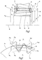
- a gear set is generally designated 10.
- the gear set 10 is for example for use in a Gear transmission suitable for motor vehicles and has a first, driving gear (hereinafter referred to as a pinion) and a second, driven gear (hereinafter called wheel) on.
- the pinion 12 is fixed to a shaft 18 along an axis 16 is aligned.
- the pinion 12 has a base body 20 on the outer periphery thereof a helical toothing 22 is formed.
- the helical gearing 22 has a root circle 24 with a root diameter d f , a tip circle 26 with a tip diameter d a and a base circle 28 with a base circle diameter d b .
- the wheel 14 has a corresponding helical toothing (in Fig. 1 unspecified).
- Fig. 2 are parameters of the helical gear 22 of the pinion 12th marked with the index "1", the corresponding parameters the helical toothing of the wheel 14 with the index "2".
- Fig. 2 the pitch circles of the two helical gears are indicated at 30.
- the pitch circle diameter of the helical gear 22 is indicated in Fig. 1 with d w .
- the pinion 12 is formed wider than the wheel 14 overall and has at both axial ends in each case one radially below of the root circle 24 lying paragraph 32.
- each is a pressure comb 34 in the form of an annular disc arranged.
- the axial outer sides of the pressure combs 34 close approximately flush with the respective axial end faces of the pinion 12 off.
- the pressure combs 34 extend in the radial direction from the respective paragraphs 32 to about the height of the top circle 26 of the helical gearing 22 (in Fig. 1 slightly beyond, in Fig. 2 to shortly before).
- the wheel 14 is disposed between the two pressure crests 34, and Although so that its helical toothing approximately at the height of axially inner contact surfaces 36 of the pressure combs 34 is located.
- the pressure combs 34 are separated in the present case from the Pinion 12 made and subsequently fixed thereto, for example by welding, gluing, a serration or in other force, material or positive manner.
- the contact surfaces 36 may be coated to reduce friction reduce, for example with a plastic coating or like.
- the pressure combs 34 also total be made of a low-friction material.
- the pressure combs 34 are integral with the pinion 12th intended.
- Fig. 3 a preferred embodiment is shown in which the pressure combs 34 'with an internal axial recess are provided so that the contact surface 36 'reduced overall becomes. It is further shown that the contact surface 36 ' lying approximately at the radial height of the pitch circle 30 and in Regarding this centered. This will be special low relative speeds in the region of the frictional contact between the axial end face of the helical toothing of the wheel 14 and the contact surface 36 'achieved.
- FIG. 4 shows a further alternative embodiment, in which the contact surface 36 "of the pressure comb 34 '' convex or spherical is executed.
- the wheel 14 is formed so that its end face in the contact area with the contact surface 36 "obliquely inwards. As a result, between the teeth of the wheel 14 and the contact surface 36 '' set up a linear contact, as shown in Fig. 4 by a contact line 56 schematically is indicated.
- Fig. 5 is on the front side of Rades 14 in the region of the teeth a circumferentially continuous Rooring provided, the outside of the contact surface of the pressure comb 34 "'comes into contact.
- Fig. 6 shows an alternative embodiment of a pressure comb 34 IV .
- the embodiment generally corresponds to that of the pressure comb 34 'of FIG. 3. In this case, however, the contact surface 36' of the pressure comb 34 IV passes over an inlet radius 60 in its outer circumference.
- a contact surface 36 "in a convex configuration is formed by an insert 62 made of plastic, which can be formed, for example, from PA, PTFE, PEEK TM or the like.
Abstract
Description
Die vorliegende Erfindung betrifft ein Zahnrad mit einem Grundkörper, einer Schrägverzahnung und einem Druckkamm, der seitlich an dem Grundkörper angeordnet ist, um Axialkräfte aufzunehmen, die beim Zahneingriff mit einem weiteren Zahnrad entstehen.The present invention relates to a toothed wheel with a base body, a helical gearing and a pressure comb, the side is arranged on the base body in order to absorb axial forces, which arise during meshing with another gear.
Ferner betrifft die vorliegende Erfindung einen Zahnradsatz aus zwei schräg verzahnten Zahnrädern, von denen eines ein solches Zahnrad ist. Furthermore, the present invention relates to a gear set two helical gears, one of which is one Gear is.
Bei Stirnradgetrieben sind die Zahnräder aus Gründen der Tragfähigkeit und der Geräuschminimierung häufig schräg verzahnt. Durch den Schrägungswinkel entstehen in der Verzahnung beim Zahneingriff Axialkräfte. Diese Axialkräfte, einschließlich der bei großen Raddurchmessern auftretenden Kippmomente, werden in der Regel an den Wellen durch Wälzlager aufgenommen, die sowohl Radial- als auch Axialkräfte aufnehmen können.For spur gears, the gears are for reasons of carrying capacity and the noise minimization often skewed. Due to the helix angle arise in the teeth in the Tooth engagement axial forces. These axial forces, including the with large wheel diameters occurring tilting moments are in usually taken on the shafts by rolling bearings, both Radial and axial forces can absorb.
Die Lager müssen entsprechend dimensioniert und ausgelegt sein. Bei großen Raddurchmessern ist infolge der Kippmomente ferner eine besonders stabile und steife Lagerung erforderlich, um eine gute Führung des Zahnrades und somit ein geringes Geräuschniveau und ausreichende Lebensdauer zu erreichen. Hierdurch sind generell größere Wälzlager, besonders steife Wellen und eine große Stützbasis der Lager erforderlich, sowie ein entsprechend steifer Radkörper. Dies alles führt zu mehr Bauraum und einem höheren Gewicht. Ebenso ist der Wirkungsgrad aufgrund der Abstützung der Axialkräfte in den Relativlagern bei Relativdrehzahlen verringert.The bearings must be dimensioned and designed accordingly. For large wheel diameters is further due to the tilting moments a particularly stable and rigid storage required to a good guidance of the gear and thus a low noise level and to achieve sufficient service life. hereby are generally larger bearings, especially stiff shafts and a large support base of the bearings required, as well Correspondingly stiff wheel body. All this leads to more space and a higher weight. Likewise, the efficiency due to the support of the axial forces in the relative bearings reduced at relative speeds.
Aus der DE 197 57 855 C2 sind Zahnradgetriebe in Druckkammausführung bekannt. Bei einer bekannten Ausführungsform (dortige Fig. 6) ist an beiden Stirnseiten des antreibenden Ritzels jeweils ein Druckkamm angebracht, die sich in radialer Richtung über die Verzahnung des Ritzels hinaus erstrecken. Die Axialkräfte werden von dem angetriebenen Rad auf eine Kraftaufnahmefläche des jeweiligen Druckkammes übertragen, die am radial äußeren Ende des Druckkammes vorgesehen ist. Hierdurch ergibt sich aufgrund der dort vorhandenen Differenzgeschwindigkeiten eine vergleichsweise hohe Reibung. Ferner muss der Druckkamm aufgrund des langen Hebels sehr massiv ausgebildet werden. From DE 197 57 855 C2 gear transmission in Druckkammausführung known. In a known embodiment (local Fig. 6) is on both end faces of the driving pinion each a pressure comb attached, extending in the radial direction extend beyond the teeth of the pinion. The axial forces are from the driven wheel to a force receiving surface transferred to the respective pressure comb, the radial outer end of the pressure comb is provided. This results due to the differential speeds available there a comparatively high friction. Furthermore, the pressure comb be made very solid due to the long lever.
Bei einer weiteren Ausführungsform der DE 197 57 855 C2 (dortige Fig. 7) weist das angetriebene Rad beidseits einen Druckkamm mit axial außenliegender Kraftübertragungsfläche auf. Die dem Ritzel zugeordneten Druckkämme sind nicht am Ritzel, sondern an der das Ritzel tragenden Welle festgelegt. Die Berührlinie der Druckkämme ist dabei nahe am Wälzkreis angeordnet. Hierdurch soll die Reibung verringert werden, und zwar aufgrund der Reduktion der Differenzgeschwindigkeiten bei gleicher Summengeschwindigkeit. Diese Zahnradanordnung weist jedoch in axialer Richtung eine große Baulänge auf.In a further embodiment of DE 197 57 855 C2 (local Fig. 7), the driven wheel on both sides of a pressure comb with axially external power transmission surface. The the Pinion associated pressure combs are not on the pinion, but on set the pinion bearing shaft. The contact line of Pressure combs is arranged close to the pitch circle. hereby the friction should be reduced, due to the reduction the differential speeds at the same sum speed. However, this gear arrangement has in axial Direction a great length.
Aus der DE 198 59 273 A1 ist ein schrägverzahnter Planetenradsatz bekannt, bei dem ein stirnseitig angeordneter radialer Druckkamm einstückig mit dem Hohlrad ausgebildet ist. Die Kontaktfläche des Druckkammes zur Axialkraftübertragung erstreckt sich in radialer Richtung über die Verzahnung des Hohlrades hinaus.From DE 198 59 273 A1 is a helical planetary gear known, in which a frontally arranged radial Pressure comb is formed integrally with the ring gear. The contact surface of the pressure comb for Axialkraftübertragung extends in the radial direction over the teeth of the ring gear out.
Vor diesem Hintergrund ist es die Aufgabe der vorliegenden Erfindung, ein axial kompaktes Zahnrad in Druckkammausführung sowie einen entsprechenden Zahnradsatz bereitzustellen, die einen hohen Wirkungsgrad aufweisen.Against this background, it is the task of the present Invention, an axially compact gear in Druckkammausführung and provide a corresponding gear set, the have a high efficiency.
Die Aufgabe wird bei dem eingangs genannten Zahnrad dadurch gelöst, dass der Druckkamm so angeordnet ist, dass er die entstehenden Axialkräfte im Bereich der Schrägverzahnung aufnimmt.The task is characterized in the aforementioned gear solved that the pressure comb is arranged so that it the resulting Absorbs axial forces in the area of the helical toothing.
Bei dem eingangs genannten Zahnradsatz wird die Aufgabe durch die Verwendung eines solchen Zahnrades gelöst. In the aforementioned gear set, the task is through solved the use of such a gear.
Durch die erfindungsgemäße Anordnung des Druckkammes werden die Axialkräfte der Verzahnung direkt an der Zahnbrust durch den Druckkamm aufgenommen.The inventive arrangement of the pressure comb are the Axialkräfte of the toothing directly at the Zahnbrust by the Pressure comb recorded.
Hierdurch werden die Gleitgeschwindigkeiten signifikant reduziert. Somit ist eine Erhöhung des Wirkungsgrades gegeben. Durch die Anordnung des Druckkammes seitlich an den Grundkörper des Zahnrades ergibt sich eine kurze axiale Bauweise.As a result, the sliding speeds are significantly reduced. Thus, an increase in the efficiency is given. By the arrangement of the pressure comb laterally to the body of the gear results in a short axial construction.
Das Zahnrad, an dessen Grundkörper der Druckkamm angeordnet ist, ist in der Regel ein antreibendes Ritzel. Das weitere Zahnrad ist in der Regel ein angetriebenes Zahnrad. Der Antrieb kann jedoch auch vertauscht werden.The gear, arranged at the base of the pressure comb is usually a driving pinion. The further Gear is usually a driven gear. The drive However, it can also be reversed.
Dabei versteht sich, dass jedenfalls dann, wenn das Zahnrad in beide Drehrichtungen angetrieben werden kann, an den gegenüberliegenden Seiten des Zahnrades jeweils ein eigener Druckkamm angeordnet ist. Demzufolge benötigt das Zahnrad dann keine axiale Lagerung. Die Positionierung des Zahnrades kann folglich allein über die Planflächen des weiteren Zahnrades erfolgen. Somit kann das Zahnrad schwimmend auf die Welle aufgesteckt werden. Hierdurch vereinfacht sich der Montageprozess.It is understood that, at least when the gear in both directions of rotation can be driven to the opposite Sides of the gear each have their own pressure comb is arranged. As a result, the gear does not need any axial storage. The positioning of the gear can therefore Alone over the flat surfaces of the other gear done. Thus, the gear can be mounted floating on the shaft become. This simplifies the assembly process.
Auch das weitere Zahnrad benötigt keine axiale Lagerung, um Axialkräfte aufzunehmen. In der Regel sind jedoch Führungslager vorgesehen, die für die Positionierung des weiteren Zahnrades sorgen. Eine besonders steife Welle oder eine breite Stützbasis sowie ein steifer Radkörper des weiteren Zahnrades sind somit nicht mehr erforderlich, da keine Axialkräfte und keine Kippmomente in den Radkörper und die Welle eingeleitet werden. Nach außen treten sowohl bei dem Zahnrad als auch bei dem weiteren Zahnrad nur Radialkräfte auf.The other gear requires no axial bearing to Absorb axial forces. As a rule, however, are guide bearings provided for the positioning of the further gear to care. A particularly stiff shaft or a wide support base and a rigid wheel body of the other gear are thus no longer necessary, as no axial forces and no tilting moments be introduced into the wheel body and the shaft. To outside kick both the gear and the other Gear only radial forces on.
Die Aufgabe wird somit vollkommen gelöst.The task is thus completely solved.
Von besonderem Vorzug ist es, wenn der Druckkamm eine ringförmige Kontaktfläche aufweist, die zu der Schrägverzahnung hinweist und dazu ausgelegt ist, beim Zahneingriff von den axialen Stirnflächen der Verzahnung des weiteren Zahnrades berührt zu werden, um die Axialkräfte aufzunehmen.Of particular preference is when the pressure comb an annular Contact surface, which indicates the helical toothing and is adapted to the tooth engagement of the axial End faces of the teeth of the other gear touches too be used to absorb the axial forces.
Durch die Maßnahme, die Axialkräfte über die ringförmige Kontaktfläche direkt von den axialen Stirnflächen der Verzahnung des weiteren Zahnrades aufzunehmen, ergeben sich deutlich geringere Differenzgeschwindigkeiten im Berührungsbereich als bei bekannten Anordnungen, bei denen die Kontaktflächen radial außerhalb der Schrägverzahnung des antreibenden Zahnrades liegen.By the measure, the axial forces on the annular contact surface directly from the axial end faces of the toothing take the other gear, resulting in much lower Differential speeds in the contact area than at known arrangements in which the contact surfaces radially lie outside the helical toothing of the driving gear.
Dabei ist es von besonderem Vorteil, wenn die Kontaktfläche in radialer Richtung kleiner bzw. kürzer ist als die Zahnhöhe der Schrägverzahnung des antreibenden Zahnrades.It is particularly advantageous if the contact surface in radial direction is smaller or shorter than the tooth height of the Helical toothing of the driving gear.
Hierdurch kann die Reibung weiter verringert werden.As a result, the friction can be further reduced.
Vorteilhaft ist es dabei ferner, wenn die Kontaktfläche von dem weiteren Zahnrad im Bereich zwischen dem Wälzkreis und dem Fußkreis des weiteren Zahnrades berührt wird. It is also advantageous if the contact surface of the another gear in the area between the pitch circle and the The foot of the other gear is touched.
Hierdurch ergibt sich ein guter Kompromiss zwischen geringer Reibung einerseits und großer Kraftübertragungsfläche zwischen der Stirnseite der Verzahnung des weiteren Zahnrades und der Kontaktfläche des Druckkammes.This results in a good compromise between less Friction on the one hand and large force transmission surface between the front side of the toothing of the further gear and the Contact surface of the pressure comb.
Von besonderem Vorteil ist es, wenn die Kontaktfläche von dem weiteren Zahnrad im Bereich des Wälzkreises berührt wird.It is particularly advantageous if the contact surface of the another gear is touched in the area of the pitch circle.
Hierdurch ergibt sich eine geringstmögliche Reibung.This results in the least possible friction.
Dabei ist es von besonderem Vorteil, wenn die Kontaktfläche in radialer Richtung um den Wälzkreis der Schrägverzahnung herum zentriert ist.It is particularly advantageous if the contact surface in radial direction around the pitch circle of the helical toothing around is centered.
Dies führt zu einer weiteren Verbesserung des Wirkungsgrades.This leads to a further improvement of the efficiency.
Von besonderem Vorteil ist es, wenn die Kontaktfläche konvex gekrümmt ist, so dass das weitere Zahnrad die Kontaktfläche entlang einer Kreislinie berührt.It is particularly advantageous if the contact surface is convex is curved so that the additional gear is the contact surface touched along a circular line.
Hierdurch ist die Berührungsfläche auf die Kreislinie reduziert, so dass die Reibung zwischen der Kontaktfläche und dem weiteren Zahnrad besonders minimiert ist.As a result, the contact surface is reduced to the circular line, so that the friction between the contact surface and the further gear is particularly minimized.
Auch ist es vorteilhaft, wenn die Kontaktfläche des Druckkammes über einen Einlaufradius in dessen Außenumfang übergeht.It is also advantageous if the contact surface of the pressure comb passes over an inlet radius in the outer periphery.
Dabei ist selbst dann, wenn die Kontaktfläche nicht auf eine Kreislinie beschränkt ist, ein gutes Zusammenspiel der Schrägverzahnungen gewährleistet. Ferner kann die Schmierung der in Eingriff stehenden Verzahnungen erleichtert werden. It is even if the contact surface is not on a Circular line is limited, a good interaction of helical gears guaranteed. Furthermore, the lubrication of the in Engaging teeth are facilitated.
Gemäß einer weiteren bevorzugten Ausführungsform erstreckt sich der Druckkamm in radialer Richtung nicht über den Kopfkreis der Schrägverzahnung hinaus.According to another preferred embodiment extends the pressure comb in the radial direction not over the top circle of Helical gearing out.
Hierdurch wird eine radial kompakte Bauweise bei geringem Materialeinsatz erzielt. Der Druckkamm kann sich bei alternativen Ausführungsformen jedoch auch über den Kopfkreis der Schrägverzahnung hinaus erstrecken.This results in a radially compact design with low material usage achieved. The pressure comb can be at alternative Embodiments, however, also on the top circle of the helical gearing extend beyond.
Ferner ist es vorteilhaft, wenn der Druckkamm als separates Element hergestellt ist, das an dem Grundkörper befestigt ist.Furthermore, it is advantageous if the pressure comb as a separate Element is made, which is attached to the body.
Hierdurch kann der Druckkamm aus einem Material hergestellt werden, das an die Aufgaben der Kraftübertragung und der Reibungsverringerung besonders angepasst ist.As a result, the pressure comb made of a material which are connected with the tasks of power transmission and Friction reduction is particularly adapted.
Der Druckkamm kann beispielsweise aus einem speziellen Stahl hergestellt sein, aber auch aus Kunststoff.For example, the pressure comb can be made of a special steel be made, but also made of plastic.
Alternativ oder zusätzlich hierzu kann die Kontaktfläche des Druckkammes reibungsarm ausgebildet sein, insbesondere aus Kunststoff.Alternatively or additionally, the contact surface of Pressure comb be designed friction, in particular from Plastic.
Mit anderen Worten kann die Kontaktfläche besonders bearbeitet oder mit einem speziellen Überzug, beispielsweise aus Kunststoff versehen sein, um die Reibung zu verringern.In other words, the contact surface can be specially processed or with a special coating, for example made of plastic be provided to reduce the friction.
Geeignete Kunststoffe sind insbesondere PA, PTFE oder ähnliches. Suitable plastics are in particular PA, PTFE or the like.
Ferner kann an den Druckkamm ein Einsatz aus einem geeigneten Kunststoff vorgesehen sein, beispielsweise PEEK™.Furthermore, an insert made of a suitable Be provided plastic, such as PEEK ™.
Bei dem erfindungsgemäßen Zahnradsatz ist es besonders vorteilhaft, wenn die Kontaktfläche des Zahnrades die Axialkräfte unmittelbar von der axialen Stirnseite der Verzahnung des weiteren Zahnrades aufnimmt, mit den oben im Detail beschriebenen Vorteilen.In the gear set according to the invention, it is particularly advantageous when the contact surface of the gear the axial forces directly from the axial end face of the toothing of the other Gear wheel receives, with those described in detail above Benefits.
Ferner ist es vorteilhaft, wenn die Kontaktfläche des Zahnrades konvex gekrümmt ist und wenn die Stirnseite der Verzahnung des weiteren Zahnrades zumindest im Kontaktbereich mit der Kontaktfläche schräg ausgerichtet ist.Furthermore, it is advantageous if the contact surface of the gear is curved convexly and when the front of the toothing of the further gear at least in the contact area with the contact surface is aligned obliquely.
Auf diese Weise lässt sich neben der Einrichtung einer Berührlinie auch eine einfache Zentrierung der Zahnräder aufeinander erzielen.In this way, in addition to the establishment of a touch line also a simple centering of the gears on each other achieve.
Dabei ist es von besonderem Vorteil, wenn die Stirnseite der Verzahnung des weiteren Zahnrades im Kontaktbereich mit der Kontaktfläche zum Kopfkreis dieser Verzahnung hin schräg nach innen zuläuft.It is particularly advantageous if the front of the Gearing of the other gear in the contact area with the Contact surface to the tip circle of this toothing obliquely to tapers in.
Auf diese Weise kann die schräge Ausrichtung zur Kontaktfläche des antreibenden Zahnrades konstruktiv einfach realisiert werden.In this way, the oblique orientation to the contact surface the driving gear constructively easy to be realized.
Es versteht sich, dass die vorstehend genannten und die nachstehend noch zu erläuternden Merkmale nicht nur in der jeweils angegebenen Kombination, sondern auch in anderen Kombinationen oder in Alleinstellung verwendbar sind, ohne den Rahmen der vorliegenden Erfindung zu verlassen.It is understood that the above and the following yet to be explained features not only in each case specified combination, but also in other combinations or be used alone, without the framework of to leave the present invention.
Ausführungsbeispiele der Erfindung sind in der Zeichnung dargestellt und werden in der nachfolgenden Beschreibung näher erläutert. Es zeigen:
- Fig. 1
- eine schematische Längsschnittansicht durch einen erfindungsgemäßen Zahnradsatz;
- Fig. 2
- eine schematische Querschnittsansicht durch einen erfindungsgemäßen Zahnradsatz;
- Fig. 3
- eine weitere Ausführungsform des erfindungsgemäßen Zahnradsatzes;
- Fig. 4
- eine weitere Ausführungsform des erfindungsgemäßen Zahnradsatzes;
- Fig. 5
- eine weitere Ausführungsform eines Zahnradsatzes;
- Fig. 6
- eine alternative Ausgestaltung eines Druckkammes; und
- Fig. 7
- eine weitere alternative Ausgestaltung eines Druckkammes.
- Fig. 1
- a schematic longitudinal sectional view through a gear set according to the invention;
- Fig. 2
- a schematic cross-sectional view through a gear set according to the invention;
- Fig. 3
- a further embodiment of the gear set according to the invention;
- Fig. 4
- a further embodiment of the gear set according to the invention;
- Fig. 5
- another embodiment of a gear set;
- Fig. 6
- an alternative embodiment of a pressure comb; and
- Fig. 7
- a further alternative embodiment of a pressure comb.
In Fig. 1 und 2 ist ein Zahnradsatz generell mit 10 bezeichnet. In Fig. 1 and 2, a gear set is generally designated 10.
Der Zahnradsatz 10 ist beispielsweise zur Verwendung in einem Zahnradgetriebe für Kraftfahrzeuge geeignet und weist ein erstes, antreibendes Zahnrad (im folgenden Ritzel genannt) und ein zweites, angetriebenes Zahnrad (im folgenden Rad genannt) auf.The gear set 10 is for example for use in a Gear transmission suitable for motor vehicles and has a first, driving gear (hereinafter referred to as a pinion) and a second, driven gear (hereinafter called wheel) on.
Das Ritzel 12 ist an einer Welle 18 festgelegt, die entlang
einer Achse 16 ausgerichtet ist.The
Das Ritzel 12 weist einen Grundkörper 20 auf, an dessen Außenumfang
eine Schrägverzahnung 22 ausgebildet ist.The
Die Schrägverzahnung 22 weist einen Fußkreis 24 mit einem Fußkreisdurchmesser
df, einen Kopfkreis 26 mit einem Kopfkreisdurchmesser
da und einen Grundkreis 28 mit einem Grundkreisdurchmesser
db auf.The
Das Rad 14 weist eine entsprechende Schrägverzahnung auf (in
Fig. 1 nicht näher bezeichnet).The
In Fig. 2 sind Parameter der Schrägverzahnung 22 des Ritzels 12
mit dem Index "1" gekennzeichnet, die entsprechenden Parameter
der Schrägverzahnung des Rades 14 mit dem Index "2".In Fig. 2 are parameters of the
In Fig. 2 sind die Wälzkreise der zwei Schrägverzahnungen mit
30 angegeben. Der Wälzkreisdurchmesser der Schrägverzahnung 22
ist in Fig. 1 mit dw bezeichnet.In Fig. 2, the pitch circles of the two helical gears are indicated at 30. The pitch circle diameter of the
Das Ritzel 12 ist insgesamt breiter ausgebildet als das Rad 14
und weist an beiden axialen Enden jeweils einen radial unterhalb
des Fußkreises 24 liegenden Absatz 32 auf. An den Absätzen
ist jeweils ein Druckkamm 34 in Form einer ringförmigen Scheibe
angeordnet. Die axialen Außenseiten der Druckkämme 34 schließen
etwa bündig mit den jeweiligen axialen Stirnseiten des Ritzels
12 ab. Die Druckkämme 34 erstrecken sich in radialer Richtung
von den jeweiligen Absätzen 32 bis etwa zur Höhe des Kopfkreises
26 der Schrägverzahnung 22 (in Fig. 1 etwas darüber hinaus,
in Fig. 2 bis kurz davor).The
Das Rad 14 ist zwischen den zwei Druckkämmen 34 angeordnet, und
zwar so, dass dessen Schrägverzahnung etwa auf der Höhe von
axial innenliegenden Kontaktflächen 36 der Druckkämme 34 liegt.The
Wenn das Ritzel 12 angetrieben wird, wird das Rad 14 je nach
Drehrichtung in eine axiale Richtung gedrückt. Hierdurch berührt
die Schrägverzahnung des Rades 14 den jeweiligen Druckkamm
34 im Bereich der Kontaktfläche 36, wie es in Fig. 2 schematisch
durch die gestrichelten Linien bei 50 angedeutet ist.When the
Demzufolge werden die Axialkräfte unmittelbar im Bereich der
Schrägverzahnung aufgenommen, also dort, wo die Relativgeschwindigkeiten
zwischen dem Ritzel 12 und dem Rad 14 vergleichsweise
gering sind. Die Axialkräfte der Verzahnung werden
folglich direkt an der Zahnbrust durch den Druckkamm 34 aufgenommen.Consequently, the axial forces are directly in the range of
Helical gear received, so where the relative velocities
between the
Demzufolge werden weder von dem Ritzel 12 noch von dem Rad 14
Axialkräfte auf die jeweiligen Wellen ausgeübt. Somit benötigt
das Ritzel keine axiale Lagerung. Die Positionierung des
Ritzels 12 kann folglich allein über das Zusammenspiel zwischen
den Stirnseiten der Schrägverzahnung des Rades 14 und den Kontaktflächen
36 der Druckkämme 34 erfolgen. Demzufolge kann das
Ritzel 12 schwimmend auf die Welle 18 aufgesteckt werden, wodurch
sich der Montageprozess vereinfacht.As a result, neither the
Für die Positionierung des Rades 14 sind ebenfalls keine Axiallager
notwendig, lediglich Führungslager, die für die Positionierung
sorgen. Weder eine besonders steife Welle, noch eine
breite Stützbasis für die Axiallagerung, noch ein steifer Radkörper
des Rades 14 sind somit erforderlich, da weder Axialkräfte,
noch Kippmomente in den Radkörper bzw. die Welle eingeleitet
werden.For the positioning of the
Die Druckkämme 34 sind im vorliegenden Fall getrennt von dem
Ritzel 12 hergestellt und nachträglich daran festgelegt, beispielsweise
durch Schweißen, Kleben, eine Kerbverzahnung oder
auf sonstige kraft-, stoff- oder formschlüssige Art und Weise.The pressure combs 34 are separated in the present case from the
Da das Ritzel 12 in beide Drehrichtungen angetrieben werden
kann, sind zwei Druckkämme 34 auf beiden Seiten des Ritzels 12
notwendig. Bei nur einer Antriebsrichtung kann ein einzelner
Druckkamm 34 hinreichend sein.Since the
Die Kontaktflächen 36 können beschichtet sein, um die Reibung zu verringern, beispielsweise mit einem Kunststoffüberzug oder ähnliches. Alternativ können die Druckkämme 34 auch insgesamt aus einem reibungsarmen Material hergestellt sein.The contact surfaces 36 may be coated to reduce friction reduce, for example with a plastic coating or like. Alternatively, the pressure combs 34 also total be made of a low-friction material.
Gemäß einer weiteren alternativen Ausgestaltung (nicht dargestellt) sind die Druckkämme 34 einstückig mit dem Ritzel 12 vorgesehen. According to a further alternative embodiment (not shown) the pressure combs 34 are integral with the pinion 12th intended.
Anstelle einer Anordnung der Druckkämme 34 an dem Ritzel können
die Druckkämme auch an dem Rad 14 angeordnet werden.Instead of an arrangement of the pressure combs 34 on the pinion can
the pressure combs are also arranged on the
In Fig. 3 ist eine bevorzugte Ausführungsform gezeigt, bei der
die Druckkämme 34' mit einer innenliegenden axialen Ausnehmung
versehen sind, so dass die Kontaktfläche 36' insgesamt verringert
wird. Ferner ist dargestellt, dass die Kontaktfläche 36'
etwa auf der radialen Höhe des Wälzkreises 30 liegt und in
Bezug auf diesen zentriert ist. Hierdurch werden besonders
geringe Relativgeschwindigkeiten im Bereich des Reibkontaktes
zwischen der axialen Stirnseite der Schrägverzahnung des Rades
14 und der Kontaktfläche 36' erzielt.In Fig. 3 a preferred embodiment is shown in which
the pressure combs 34 'with an internal axial recess
are provided so that the contact surface 36 'reduced overall
becomes. It is further shown that the contact surface 36 '
lying approximately at the radial height of the
Fig. 4 zeigt eine weitere alternative Ausführungsform, bei der
die Kontaktfläche 36" des Druckkammes 34'' konvex bzw. ballig
ausgeführt ist.FIG. 4 shows a further alternative embodiment, in which
the
Das Rad 14 ist so ausgebildet, dass dessen Stirnseite im Kontaktbereich
mit der Kontaktfläche 36" schräg nach innen zuläuft.
Hierdurch wird zwischen der Verzahnung des Rades 14 und
der Kontaktfläche 36'' eine linienförmige Berührung eingerichtet,
wie es in Fig. 4 durch eine Kontaktlinie 56 schematisch
angedeutet ist.The
Bei der Ausführungsform der Fig. 5 ist an der Stirnseite des
Rades 14 im Bereich von dessen Verzahnung ein umfänglich durchgehender
Anlagering vorgesehen, dessen Außenseite mit der Kontaktfläche
des Druckkammes 34"' in Berührung tritt. In the embodiment of Fig. 5 is on the front side of
Fig. 6 zeigt eine alternative Ausführungsform eines Druckkammes
34IV. Die Ausführungsform entspricht generell jener des Druckkammes
34' der Fig. 3. Dabei geht jedoch die Kontaktfläche 36'
des Druckkammes 34IV über einen Einlaufradius 60 in dessen
Außenumfang über.Fig. 6 shows an alternative embodiment of a
Hierdurch wird gewährleistet, dass das Ineinanderspiel der
Verzahnungen durch den Druckkamm 34IV nicht negativ beeinflusst
wird.This ensures that the interplay of the teeth by the
Bei einer weiteren Ausführungsform des Druckkammes 34v (siehe
Fig. 7) ist eine Kontaktfläche 36'' in konvexer Ausgestaltung
durch einen Einsatz 62 aus Kunststoff gebildet, der beispielsweise
aus PA,PTFE, PEEK™ oder ähnliches gebildet sein kann.In a further embodiment of the pressure comb 34 v (see FIG. 7), a
Claims (15)
dadurch gekennzeichnet, dass
der Druckkamm (34) so angeordnet ist, dass er die entstehenden Axialkräfte im Bereich der Schrägverzahnung (22) aufnimmt.Gear (12) having a base body (20), a helical toothing (22) and a pressure comb (34), which is arranged laterally on the base body (20) to absorb axial forces that arise during tooth engagement with a further gear (14),
characterized in that
the pressure comb (34) is arranged so that it absorbs the resulting axial forces in the region of the helical toothing (22).
Applications Claiming Priority (2)
| Application Number | Priority Date | Filing Date | Title |
|---|---|---|---|
| DE10329870 | 2003-07-02 | ||
| DE2003129870 DE10329870B3 (en) | 2003-07-02 | 2003-07-02 | Gear and gear set |
Publications (1)
| Publication Number | Publication Date |
|---|---|
| EP1493947A1 true EP1493947A1 (en) | 2005-01-05 |
Family
ID=33426827
Family Applications (1)
| Application Number | Title | Priority Date | Filing Date |
|---|---|---|---|
| EP04014953A Withdrawn EP1493947A1 (en) | 2003-07-02 | 2004-06-25 | Gearwheel and set of gearwheels |
Country Status (2)
| Country | Link |
|---|---|
| EP (1) | EP1493947A1 (en) |
| DE (1) | DE10329870B3 (en) |
Cited By (8)
| Publication number | Priority date | Publication date | Assignee | Title |
|---|---|---|---|---|
| WO2008067979A2 (en) * | 2006-12-07 | 2008-06-12 | Getrag Getriebe- Und Zahnradfabrik Hermann Hagenmeyer Gmbh & Cie Kg | Rattle-free mating of components |
| DE102009031240A1 (en) | 2009-07-01 | 2011-01-05 | Schaeffler Technologies Gmbh & Co. Kg | Geared connection has two toothed wheels present in tooth engagement, where one toothed wheel has unit for damping noise, which has multiple toothed washers arranged axially adjacent to each other |
| JP2013534586A (en) * | 2010-06-24 | 2013-09-05 | エフ・エー・ファウ・ゲゼルシャフト・ミト・ベシュレンクテル・ハフツング | Working machine |
| EP3080484A4 (en) * | 2013-12-09 | 2017-10-11 | Northeastern University | 4-point convex contact roller bearing for compact planetary drive train |
| EP2976549A4 (en) * | 2013-03-22 | 2018-02-14 | Northeastern University | Curved bearing contact system |
| US10174810B2 (en) | 2006-06-21 | 2019-01-08 | Northeastern University | Curved bearing contact system |
| DE102017223018A1 (en) | 2017-12-18 | 2019-06-19 | Zf Friedrichshafen Ag | gear transmission |
| EP4353480A1 (en) * | 2022-10-13 | 2024-04-17 | Bodenmüller Hörburger Schratt Antriebstechnik GmbH & Co. KG | Gearbox with shaft with additive pressure comb and method for producing a shaft |
Families Citing this family (7)
| Publication number | Priority date | Publication date | Assignee | Title |
|---|---|---|---|---|
| DE102005043477A1 (en) * | 2005-09-13 | 2007-03-15 | GM Global Technology Operations, Inc., Detroit | Gear shaft with reverse pinion |
| DE102007026078B4 (en) * | 2007-05-27 | 2017-03-02 | Robert Bosch Gmbh | System of starting device and internal combustion engine, starting device and internal combustion engine |
| DE102011104279A1 (en) | 2011-06-10 | 2012-12-13 | Getrag Getriebe- Und Zahnradfabrik Hermann Hagenmeyer Gmbh & Cie Kg | Automotive powertrain |
| DE102012205368A1 (en) * | 2012-04-02 | 2013-10-02 | Zf Friedrichshafen Ag | Gear arrangement of a rail vehicle |
| DE102014207431A1 (en) * | 2014-04-17 | 2015-10-22 | Siemens Aktiengesellschaft | Gear with pressure comb and manufacturing |
| DE102015213013A1 (en) | 2015-07-13 | 2017-01-19 | Zf Friedrichshafen Ag | transmission |
| DE102018221419A1 (en) * | 2018-12-11 | 2020-06-18 | Zf Friedrichshafen Ag | transmission |
Citations (4)
| Publication number | Priority date | Publication date | Assignee | Title |
|---|---|---|---|---|
| DE2110252A1 (en) * | 1971-03-04 | 1972-09-21 | Bhs Bayerische Berg | Spur gears planetary gear |
| DE2620570A1 (en) * | 1976-05-10 | 1977-11-17 | Bhs Bayerische Berg | SINGLE HELICAL GEAR PLANETARY GEARBOX |
| DE3311310C1 (en) * | 1983-03-28 | 1984-06-20 | Bhs Bayerische Berg | Planetary gear, which is arranged between a flow machine and an electrical machine in a housing |
| DE4216397A1 (en) * | 1992-05-18 | 1993-11-25 | Zahnradfabrik Friedrichshafen | Epicyclic helical gearbox for vehicles - has thrust rings between gears to support axial force |
Family Cites Families (2)
| Publication number | Priority date | Publication date | Assignee | Title |
|---|---|---|---|---|
| DE19757855C2 (en) * | 1997-12-24 | 2002-10-24 | Albert Dick | Devices for the injection lubrication of gear drives |
| DE19859273A1 (en) * | 1998-12-22 | 2000-06-29 | Zahnradfabrik Friedrichshafen | Planetary gear |
-
2003
- 2003-07-02 DE DE2003129870 patent/DE10329870B3/en not_active Expired - Fee Related
-
2004
- 2004-06-25 EP EP04014953A patent/EP1493947A1/en not_active Withdrawn
Patent Citations (4)
| Publication number | Priority date | Publication date | Assignee | Title |
|---|---|---|---|---|
| DE2110252A1 (en) * | 1971-03-04 | 1972-09-21 | Bhs Bayerische Berg | Spur gears planetary gear |
| DE2620570A1 (en) * | 1976-05-10 | 1977-11-17 | Bhs Bayerische Berg | SINGLE HELICAL GEAR PLANETARY GEARBOX |
| DE3311310C1 (en) * | 1983-03-28 | 1984-06-20 | Bhs Bayerische Berg | Planetary gear, which is arranged between a flow machine and an electrical machine in a housing |
| DE4216397A1 (en) * | 1992-05-18 | 1993-11-25 | Zahnradfabrik Friedrichshafen | Epicyclic helical gearbox for vehicles - has thrust rings between gears to support axial force |
Cited By (14)
| Publication number | Priority date | Publication date | Assignee | Title |
|---|---|---|---|---|
| US10174810B2 (en) | 2006-06-21 | 2019-01-08 | Northeastern University | Curved bearing contact system |
| WO2008067979A3 (en) * | 2006-12-07 | 2008-08-14 | Getrag Getriebe Zahnrad | Rattle-free mating of components |
| WO2008067979A2 (en) * | 2006-12-07 | 2008-06-12 | Getrag Getriebe- Und Zahnradfabrik Hermann Hagenmeyer Gmbh & Cie Kg | Rattle-free mating of components |
| DE102009031240A1 (en) | 2009-07-01 | 2011-01-05 | Schaeffler Technologies Gmbh & Co. Kg | Geared connection has two toothed wheels present in tooth engagement, where one toothed wheel has unit for damping noise, which has multiple toothed washers arranged axially adjacent to each other |
| JP2013534586A (en) * | 2010-06-24 | 2013-09-05 | エフ・エー・ファウ・ゲゼルシャフト・ミト・ベシュレンクテル・ハフツング | Working machine |
| EP2976549A4 (en) * | 2013-03-22 | 2018-02-14 | Northeastern University | Curved bearing contact system |
| EP3080484A4 (en) * | 2013-12-09 | 2017-10-11 | Northeastern University | 4-point convex contact roller bearing for compact planetary drive train |
| DE102017223018A1 (en) | 2017-12-18 | 2019-06-19 | Zf Friedrichshafen Ag | gear transmission |
| WO2019120798A1 (en) | 2017-12-18 | 2019-06-27 | Zf Friedrichshafen Ag | Gearwheel transmission |
| CN111492154A (en) * | 2017-12-18 | 2020-08-04 | Zf 腓德烈斯哈芬股份公司 | Gear transmission device |
| US11603907B2 (en) | 2017-12-18 | 2023-03-14 | Zf Friedrichshafen Ag | Gearwheel transmission |
| CN111492154B (en) * | 2017-12-18 | 2023-05-05 | Zf 腓德烈斯哈芬股份公司 | Gear transmission device |
| EP4353480A1 (en) * | 2022-10-13 | 2024-04-17 | Bodenmüller Hörburger Schratt Antriebstechnik GmbH & Co. KG | Gearbox with shaft with additive pressure comb and method for producing a shaft |
| DE102022126742A1 (en) | 2022-10-13 | 2024-04-18 | Bodenmüller Hörburger Schratt Antriebstechnik GmbH & Co. KG | Gearbox with shaft with additive pressure comb and method for producing a shaft |
Also Published As
| Publication number | Publication date |
|---|---|
| DE10329870B3 (en) | 2005-01-27 |
Similar Documents
| Publication | Publication Date | Title |
|---|---|---|
| DE10124265B4 (en) | pump | |
| EP0839293B1 (en) | Planetary gear | |
| DE3738521C1 (en) | Planetary gear | |
| DE10329870B3 (en) | Gear and gear set | |
| EP2221510B1 (en) | Planet wheel with a bolt comprising an axial nut | |
| EP1429054A2 (en) | Planetary gearing | |
| DE102012103147A1 (en) | LOS BEARING FOR A STEERING GEAR | |
| DE102004006723A1 (en) | planetary gear | |
| DE102012219212A1 (en) | Spur gear differential for use as e.g. distribution, branching, and axle differential gear box in motor car, has coupling and circulation planetary parts formed such that cladding circle is smaller than addendum circle of teeth | |
| DE102004034823A1 (en) | Wave motion gear apparatus has tooth root side which tooth profile curves has obliquity action angle which is smaller than standard pressure angle of basic rack tooth profile curve | |
| DE102005024388B4 (en) | Continuously variable belt-type transmission | |
| EP1440254B1 (en) | Gearing with lubrication grooves | |
| EP0949419B1 (en) | Internal gear pump | |
| EP3982005B1 (en) | Coaxial transmission | |
| EP2646712B1 (en) | Gear mechanism having helical toothing | |
| DE3022020C2 (en) | Axial power transmission device for a spur gear | |
| DE10203983B4 (en) | transmission | |
| EP3169913B1 (en) | Harmonic drive with dry run | |
| EP0432349B1 (en) | Transmission | |
| DE19951988B4 (en) | Planetary friction gear with pressing means | |
| EP1831590B1 (en) | Device, especially a planet gear, comprising an annular base body | |
| EP1756440B1 (en) | Grooved profile for a hub shaft connection | |
| DE102019212220B4 (en) | harmonic drive | |
| EP3828444A1 (en) | Transmission | |
| DE19907912C2 (en) | eccentric |
Legal Events
| Date | Code | Title | Description |
|---|---|---|---|
| PUAI | Public reference made under article 153(3) epc to a published international application that has entered the european phase |
Free format text: ORIGINAL CODE: 0009012 |
|
| AK | Designated contracting states |
Kind code of ref document: A1 Designated state(s): AT BE BG CH CY CZ DE DK EE ES FI FR GB GR HU IE IT LI LU MC NL PL PT RO SE SI SK TR |
|
| AX | Request for extension of the european patent |
Extension state: AL HR LT LV MK |
|
| 17P | Request for examination filed |
Effective date: 20050617 |
|
| AKX | Designation fees paid |
Designated state(s): FR IT |
|
| REG | Reference to a national code |
Ref country code: DE Ref legal event code: 8566 |
|
| STAA | Information on the status of an ep patent application or granted ep patent |
Free format text: STATUS: THE APPLICATION IS DEEMED TO BE WITHDRAWN |
|
| 18D | Application deemed to be withdrawn |
Effective date: 20060411 |