EP1493919A2 - Starter für eine Brennkraftmaschine - Google Patents
Starter für eine Brennkraftmaschine Download PDFInfo
- Publication number
- EP1493919A2 EP1493919A2 EP04008838A EP04008838A EP1493919A2 EP 1493919 A2 EP1493919 A2 EP 1493919A2 EP 04008838 A EP04008838 A EP 04008838A EP 04008838 A EP04008838 A EP 04008838A EP 1493919 A2 EP1493919 A2 EP 1493919A2
- Authority
- EP
- European Patent Office
- Prior art keywords
- threaded sleeve
- starter
- pinion
- starter according
- shaft
- Prior art date
- Legal status (The legal status is an assumption and is not a legal conclusion. Google has not performed a legal analysis and makes no representation as to the accuracy of the status listed.)
- Withdrawn
Links
- 239000007858 starting material Substances 0.000 title claims abstract description 74
- 238000002485 combustion reaction Methods 0.000 title claims description 17
- 239000002131 composite material Substances 0.000 claims description 4
- 238000006073 displacement reaction Methods 0.000 description 6
- 230000005540 biological transmission Effects 0.000 description 4
- 229910000831 Steel Inorganic materials 0.000 description 2
- 230000001133 acceleration Effects 0.000 description 2
- 238000012432 intermediate storage Methods 0.000 description 2
- 239000002184 metal Substances 0.000 description 2
- 238000000034 method Methods 0.000 description 2
- 238000000926 separation method Methods 0.000 description 2
- 239000010959 steel Substances 0.000 description 2
- 238000004804 winding Methods 0.000 description 2
- 230000001419 dependent effect Effects 0.000 description 1
- 238000003780 insertion Methods 0.000 description 1
- 230000037431 insertion Effects 0.000 description 1
- 238000003754 machining Methods 0.000 description 1
- 239000000463 material Substances 0.000 description 1
- 238000007493 shaping process Methods 0.000 description 1
- 238000003860 storage Methods 0.000 description 1
Images


Classifications
-
- F—MECHANICAL ENGINEERING; LIGHTING; HEATING; WEAPONS; BLASTING
- F02—COMBUSTION ENGINES; HOT-GAS OR COMBUSTION-PRODUCT ENGINE PLANTS
- F02N—STARTING OF COMBUSTION ENGINES; STARTING AIDS FOR SUCH ENGINES, NOT OTHERWISE PROVIDED FOR
- F02N15/00—Other power-operated starting apparatus; Component parts, details, or accessories, not provided for in, or of interest apart from groups F02N5/00 - F02N13/00
- F02N15/02—Gearing between starting-engines and started engines; Engagement or disengagement thereof
- F02N15/022—Gearing between starting-engines and started engines; Engagement or disengagement thereof the starter comprising an intermediate clutch
- F02N15/023—Gearing between starting-engines and started engines; Engagement or disengagement thereof the starter comprising an intermediate clutch of the overrunning type
-
- F—MECHANICAL ENGINEERING; LIGHTING; HEATING; WEAPONS; BLASTING
- F02—COMBUSTION ENGINES; HOT-GAS OR COMBUSTION-PRODUCT ENGINE PLANTS
- F02N—STARTING OF COMBUSTION ENGINES; STARTING AIDS FOR SUCH ENGINES, NOT OTHERWISE PROVIDED FOR
- F02N15/00—Other power-operated starting apparatus; Component parts, details, or accessories, not provided for in, or of interest apart from groups F02N5/00 - F02N13/00
- F02N15/02—Gearing between starting-engines and started engines; Engagement or disengagement thereof
- F02N15/04—Gearing between starting-engines and started engines; Engagement or disengagement thereof the gearing including disengaging toothed gears
- F02N15/06—Gearing between starting-engines and started engines; Engagement or disengagement thereof the gearing including disengaging toothed gears the toothed gears being moved by axial displacement
Definitions
- the invention relates to a starter for an internal combustion engine according to Preamble of claim 1.
- Such a Screwdriver starter has an electric starter motor, whose drive shaft with a displaceable in the direction of its longitudinal axis Output shaft is in operative connection.
- the drive shaft is at a remote end of the starter motor with a coarse thread provided on the rotatable and displaceable Mit supportiveschaft the output shaft is arranged.
- This entrainment of the Output shaft is over a freewheel with a pinion having Shank connected.
- the starter motor is the Output shaft with the Mitauerschaft, the freewheel and the pinion shaft so vorgespurt that the pinion into a gear wheel of the internal combustion engine meshes.
- This gear is normally locked connected to a crankshaft of the internal combustion engine and is typical formed as external teeth on a flywheel.
- Starter is known from DE 100 16 706 A1.
- This well-known starter motor has a pole tube, which when energized the motor performs a pivoting movement about the motor axis.
- a braking mechanism in Gear set With this Pivoting movement of the pole tube is a braking mechanism in Gear set, which has a braking torque on the driving force of the Output shaft exerts.
- This braking torque causes the Mit supportiveschaft over the coarse thread of the drive shaft of the engine is driven so that the pinion of the starter in the sprocket the internal combustion engine einspurt.
- a generic ertrieb starter for cranking a Internal combustion engine is known from WO 03/008798 A1.
- this known starter is a feed of an output shaft for Traces of a pinion in the ring gear of an internal combustion engine by means of a pole tube arranged on the stator of the starter motor causes, when energized the starter motor pivotal movement around the motor axle experiences.
- a starter for an internal combustion engine has a starter motor and a drivable by this Drive shaft and one in operative connection with the drive shaft, displaceable in the direction of its longitudinal axis output shaft on, which with a pinion shaft with a in a sprocket the Internal combustion engine engageable pinion is coupled.
- a feed the output shaft for meshing the pinion in the sprocket can in particular by means of a provided on the starter of the starter motor Elements take place when energizing the starter motor undergoes a pivoting movement about the motor axis.
- the driver unit at least out two radially in the direction of rotation coupled to each other and axially against each other consists of sliding elements.
- the driver unit Due to the two-part design of the driver unit, the be reduced to accelerating mass when starting. If the starter pinion due to its inertia and frictional forces between Sprocket and starter pinion faces is braked, Nevertheless, the Einspurfeder can be further biased. By The lower mass of the track unit may end up with the pinion Einspurfest very quickly at a tooth gap position in the Sprocket to be accelerated.
- the spring force can act in particular on a drive plate, coupled with a threaded sleeve and axially displaceable on this is.
- the threaded sleeve is preferably on the drive shaft stored and with this by means of a steep thread form-fitting coupled.
- the threaded sleeve and the driver by means of a positive connection in the direction of rotation with each other coupled.
- This positive connection can, for example, in the form an external toothing on the threaded sleeve and a corresponding thereto Internal teeth on the drive plate exist.
- the external teeth of the threaded sleeve and the internal teeth the drive plate can be used in particular as a degree gear teeth be formed, for example. As triangular gears or the like.
- the threaded sleeve can in an advantageous embodiment of a lighter material than steel, for example. Plastic or a composite material be made. In this way their can be accelerated Mass be reduced significantly.
- the pinion shaft via the threaded sleeve is indirectly supported, so that the pinion shaft a defined storage and thus has a perfect concentricity.
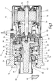
- the illustrated in Figure 1 as a longitudinal section starter 10 has a two-part housing, wherein a first housing part 12 a Starter motor 11 surrounds and a second housing part 14, the drive bearing (not shown) of the starter.
- the starter motor 11 includes in known manner a stator 16 and a rotatable therein mounted rotor 18.
- the stator 16 has a pole tube 20 and therein arranged, designed as permanent magnets stator poles 22.
- the pole tube 20 forms the magnetic return for the stator poles 22, which are arranged concentrically around the rotor 18 around.
- the rotor 18 has a motor shaft 24 which is provided with a laminated core rotatably connected. In not shown grooves of the laminated core one or more rotor windings are introduced.
- the emerging from the starter motor 11 motor shaft 24 is connected to a Transmission, preferably a planetary gear 26 coupled.
- the motor shaft 24 drives a sun gear 28, and the sun gear 28 meshes with planetary gears 30 and 32, which in turn roll off a ring gear 34.
- the ring gear 34 is connected to an intermediate bearing 36 connected.
- the planet gears 30 and 32 are from a Planet carrier 38 held.
- the intermediate storage 36 is stationary and rotatably disposed in the second housing part 14 of the starter 10.
- Of the Planet carrier 38 is rotationally fixed, e.g. integral with a drive shaft 40 connected.
- a threaded sleeve 42 is set on the drive shaft 40.
- the drive shaft 40 and the coaxial with this arranged threaded sleeve 42 are coupled via a coarse thread 44 with each other. That is, at one Inner lateral surface of the threaded sleeve 42 and at a portion an outer circumferential surface of the drive shaft 40 is one each Steep thread toothing applied.
- This the drive shaft 40th and the threaded sleeve 42 connecting coarse thread 44th represents a so-called Einspurgetriebe.
- the threaded sleeve 42nd has an outer toothing at a portion of its outer periphery 46, in which an internal toothing 48 of a drive plate 50 engages.
- the drive plate 50 goes into an outer ring 52 of a freewheel 54 via.
- the outer ring 52 of the freewheel 54 drives via not shown Clamping an inner ring 56, which with a pinion shaft 58th connected is.
- the pinion shaft 58 At his from the second housing part 14 of the starter 10 pointed end is the pinion shaft 58 with a pinion 60 provided with spur toothing.
- the pinion shaft 58 experiences upon rotation of the motor shaft 24 by the helical thread 44 running Einspurgetriebe between the drive shaft 40 and the output shaft 43 a feed, so that the pinion 60 in a sprocket 62 einspurt an internal combustion engine, not shown.
- Einspurvorgang and the Ausspurvorgang will be in the following described in more detail.
- the drive shaft 40 is within the threaded sleeve 42, drive plate 50 with freewheel 54 and pinion shaft 58 formed output shaft 43 rotatably mounted (not shown). Furthermore, it is the output shaft 43 preferably in the second housing part 14th via at least one bearing (not shown) about its longitudinal axis rotatably mounted.
- the pole tube 20 of the starter motor 11 is about the axis of rotation of the motor shaft 24 pivotable at a certain angle (about 10 ° to 30 °) stored.
- On the pole tube 20 are one or more - for example three arms 64 extending into the second housing part 14, in which the transmission is for driving the output shaft 43, extend into it.
- Each arm 64 of the pole tube 20 is through a Recess 66 on the outer circumference of the second housing part 14th rotatably arranged intermediate bearing 36 out. Every recess 66 on the intermediate bearing 36 or on a brush holder 83 has two Stops 68 and 70 on which the pivoting movement of the pole tube Limit 20 around the motor axis.
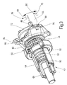
- a recess 66 on Intermediate bearing 36 with its two stops 68 and 70 and a guided therein arm 64 of the pole tube 20 shows the perspective Representation of a section of the starter 10 in the figure 3.
- the starter motor acts on the pole tube 20 due of prevailing between the rotor 18 and stator 16 electromagnetic Forces a torque, causing the pole tube 20 in a certain direction, e.g. clockwise around the motor axis is turned. It is a spring element not shown in the drawing provided, which this torque of the pole tube 20th counteracts.
- the spring element can eg. At the intermediate storage 36th be installed. The height of the torque acting on the pole tube 20 depends on the strength of the current flowing through the rotor winding Power off.
- a substantially radially projecting disc 72 mounted so that they are around the Axle of the threaded sleeve 42 of the output shaft is rotatable. Against one axial displacement against the feed direction of the threaded sleeve 42, the disc 72 is secured. This is done, for example, by means of an on the threaded sleeve 42 patch retaining ring 74, on which the disc 72 is present. The retaining ring 74 is by means of a locking ring 76th against an axial displacement against the feed direction of the Output shaft 43 secured.
- a Support ring 78 placed on the threaded sleeve 42, of a on the outer ring 52 of the freewheel 54 supporting spring 80 against the Disk 72 is pressed.
- This spring is due to its function when meshing the pinion 60 in the ring gear 62 below designated as Einspurfeder 80.
- a further spring 82 is inserted, which as the Einspurfeder 80 a pressure on the disc 72 and thus on the output shaft 43 against the feed direction of the output shaft 43 exercises.
- This second spring is hereinafter referred to as Ausspurfeder 82 indicates because they are out of the pinion 60 from the ring gear 62 supported.
- FIG. 2 illustrates in a semi-longitudinal section, the arrangement of central assembly for transmitting the rotational movement of the starter motor 11 on the pinion shaft 58 and the generation of the Traces of the pinion 60 in the ring gear 62 necessary feed movement.
- the coarse thread 44 of the drive shaft 40 via which a rotary and feed movement on the threaded sleeve 42 is transferable.
- the threaded sleeve 42 on its inner circumference with a coarse thread 44 of the drive shaft 40 corresponding coarse thread on.
- On the outer circumference is at the starter motor 11 facing Side of the threaded sleeve 42 an external toothing 46 is provided, with the corresponding internal teeth 48 of the drive plate 50 corresponds.
- threaded sleeve 42 and drive plate 50 independently from each other in the axial direction against each other be moved.
- FIG. 3 shows a perspective partial sectional view of the assembly corresponding to Figure 2, in particular, the rotation the disc 72 by means of engaging in second recesses 84 Arms 64 is illustrated.
- a slimmer end section each Arms 64 has chamfers, which by sliding on the stops 86 and 88 of each second recess 84 for a axial feed of the disc 72 can provide in Einspurides.
- the pinion shaft 58 with the thereto End-mounted pinion 60 in Einspurettivoten in Einspurides i. in the direction to the ring gear (not shown) of the internal combustion engine shifts.
- the Ausspureder 82 disposed within the pinion shaft 58 and is supported between a stop disc 90 at the axial end of the Pinion 60 and a radial support collar 92 of the threaded sleeve 42nd from.
- the spring force of the Ausspurfeder 82 is thus the spring force of Einspurfeder the 80 opposite and ensures a trace of the Pinion 60, as soon as the axial force component through the axially displaced Disc 72 is eliminated. This is the case when the starter motor 11 is no longer energized, the pole tube 20 in its initial position turns back and the arms 64 again in one of the arrow directions Swing back.
- the explained with reference to Figures 1 to 3 way to apply the axial feed force on the output shaft provides only one of several possible variants. This variant is thus not restrictive to understand.
- the axial force component can optionally also by means of a separately operable by the drive motor Actuator done, for example. By means of an electromagnet, the via suitable actuating arms causes a feed of the output shaft.
- FIG. 4 illustrates in particular the axial Displacement of the provided with the external teeth 46 threaded sleeve 42 in the axial direction in the with the internal teeth 48th provided drive plate 50.
- the teeth are shown in the Embodiment designed as a straight toothing.
- Figure 6 illustrates the design of the threaded sleeve 42, the at the the support collar 92 side facing away from the toothed outer circumference a recess 94 for receiving the locking ring 76 to the axial Fixing the retaining ring 74 and the disc 72 has.
- One to External teeth 46 directed stop surface 96 on the support collar 92nd at the same time forms an axial stop, the displaceability the threaded sleeve 42 is limited against the drive plate 50.
- the drive plate 50 can in particular be extruded from a metal become.
- the threaded sleeve 42 may, for example. Metal or consist of a suitable composite material.
- the disc 72 When energizing the starter motor 11, the disc 72 is in shifted axial direction, which also the pinion shaft 58 in the direction is moved to the ring gear 62.
- This axial movement of the pinion shaft 58 is determined by the inertia of the Einspurtechnik and a sliding of the threaded sleeve 42 via the coarse thread 44 due the rotational movement of the motor shaft 24 is supported. Support takes place at the beginning of the Einspurvorgangs only in weak Extent.
- the two-part driver according to the invention consisting of threaded sleeve 42 and drive plate 50 allows it now in an advantageous Way to further compress the lane of the 80, when a tooth-on-tooth position of the pinion 60 on the Toothed ring 62 prevents complete meshing first. Due to the friction between the end faces of the pinion 60 and the Sprocket 62, the rotational movement of the starter pinion 60 first braked.
- the already rotating starter motor 11 provides through the coarse thread for an axial displacement of the threaded sleeve 42 in a rectilinear Form fit axially within the drive plate 50, whereby at the same time the Einspurfeder 80 are biased further can. If a tooth gap is subsequently found, then the Einspurfeder 80 the starter pinion 60 in the ring gear 62 into it. Due to the additional frictional torque between the tooth flanks within the possible bolting path the entire pick-up unit by the rotating starter motor 11 via the coarse thread 44 screwed into the ring gear 62, even if already the maximum Displacement of the disc 72 and thus the threaded sleeve 42 against the drive plate 50 is reached.
- the division according to the invention of the Einspuriser allows a reduction in the acceleration of the starter motor 11 to be accelerated Mass, allowing the pinion 60 as possible when cranking quickly accelerated to the next tooth gap of the ring gear 62 is turned on and the internal combustion engine successfully can be.
- a sufficiently high biasing force of the Einspurfeder 80 and a small mass to be accelerated can by a Separation and axial displacement with simultaneous radial Positive connection of Einspuriser in a threaded sleeve and a drive plate be achieved.
- Rotational movement of the pole tube 20 can be used to at a Tooth-on-tooth position to further bias the Einspurfeder 80.
- the mass to be accelerated can be reduced.
- the each other sliding parts threaded sleeve 42 and drive plate 50th are in so-called. Free-launching starters inside the starter housing and are thus secured against ingress of dirt. If the starter motor 11 is already rotating, the starter pinion 60 but on Reason for its inertia and friction between sprocket and starter pinion faces is braked, can now the starter motor 11 via the coarse thread 44 of the drive shaft 40 and the threaded sleeve 42 move this axially further against the drive plate 50 and biasing the lashing spring 80 further therewith.
- the now lower Mass of the Einauge unit can at the end of the screw very accelerated quickly in toothed position in the ring gear 62 become.
- the driver can be very be built flat and in an advantageous manner, for example, in one operation be pressed together with the internal toothing 48.
- the subsequent machining effort for final shaping is relatively low.
- a broaching process can be omitted, since the drive plate 50 has no coarse thread more, because this was displaced into the threaded sleeve 42.
- the threaded sleeve 42 may depending on the strength requirements Steel, made of plastic or of a composite material become.
Landscapes
- Engineering & Computer Science (AREA)
- Chemical & Material Sciences (AREA)
- Combustion & Propulsion (AREA)
- Mechanical Engineering (AREA)
- General Engineering & Computer Science (AREA)
- Connection Of Motors, Electrical Generators, Mechanical Devices, And The Like (AREA)
Abstract
Description
- Figur 1
- einen schematischen Längsschnitt eines erfindungsgemäßen Starters in einer ersten Variante,
- Figur 2
- einen schematischen Halbschnitt eines Teils des Starters gemäß Figur 1,
- Figur 3
- einen perspektivischen Teilschnitt des Starters in einer modifizierten Variante,
- Figur 4
- eine Mitnehmerscheibe sowie eine damit koppelbare Gewindehülse des Starters,
- Figur 5
- die Mitnehmerscheibe gemäß Figur 4 in einer gedrehten Ansicht und
- Figur 6
- die Gewindehülse gemäß Figur 4 in vergrößerter Perspektivdarstellung.
Claims (12)
- Starter für eine Brennkraftmaschine, mit einem Startermotor (11), einer von diesem antreibbaren Antriebswelle (40) und einer mit der Antriebswelle (40) in Wirkverbindung stehenden, in Richtung ihrer Längsachse verschiebbaren Abtriebswelle (43), welche mit einer Ritzelwelle (58) mit einem in einen Zahnkranz (62) der Brennkraftmaschine einspurbaren Ritzel (60) gekoppelt ist, wobei ein Vorschub der Abtriebswelle (43) zum Einspuren des Ritzels (60) in den Zahnkranz (62) insbesondere mittels eines Vorschubs einer auf der Abtriebswelle (43) gelagerten, um diese drehbare und axial in Vorschubrichtung gegen eine Federkraft abgestützte Scheibe (72) erfolgt, deren Vorschub in eine auf die Ritzelwelle (58) wirkende Axialbewegung umsetzbar ist, wobei die Federkraft zwischen einer Mitnehmereinheit, die auf der Antriebswelle (40) gelagert und mit dieser mittels eines Steilgewindes (44) formschlüssig gekoppelt ist, und der Scheibe (72) wirkt, dadurch gekennzeichnet, dass die Mitnehmereinheit zumindest aus zwei radial in Drehrichtung miteinander gekoppelten und axial gegeneinander verschiebbaren Elementen (42, 50) besteht.
- Starter nach Anspruch 1, dadurch gekennzeichnet, dass die Mitnehmereinheit eine Gewindehülse (42) und eine damit koppelbare Mitnehmerscheibe (50) umfasst.
- Starter nach Anspruch 2, dadurch gekennzeichnet, dass die Federkraft zwischen der Scheibe (72) und der Mitnehmerscheibe (50) wirkt, die mit der Gewindehülse (42) radial formschlüssig gekoppelt und gegen diese axial verschiebbar ist.
- Starter nach Anspruch 2 oder 3, dadurch gekennzeichnet, dass die Gewindehülse (42) auf der Antriebswelle (40) gelagert und mit dieser mittels eines Steilgewindes (44) formschlüssig gekoppelt ist.
- Starter nach einem der Ansprüche 2 bis 4, dadurch gekennzeichnet, dass die Gewindehülse (42) und die Mitnehmerscheibe (50) mittels einer Formschlussverbindung in Drehrichtung miteinander gekoppelt sind.
- Starter nach Anspruch 5, dadurch gekennzeichnet, dass die Gewindehülse (42) eine Außenverzahnung (46) und die Mitnehmerscheibe (50) eine damit korrespondierende Innenverzahnung (48) aufweist.
- Starter nach Anspruch 6, dadurch gekennzeichnet, dass die Außenverzahnung (46) der Gewindehülse (42) und die Innenverzahnung (48) der Mitnehmerscheibe (50) jeweils als Geradverzahnungen ausgebildet sind.
- Starter nach Anspruch 6 oder 7, dadurch gekennzeichnet, dass die Verzahnungen als Dreiecksverzahnungen ausgebildet sind.
- Starter nach einem der voranstehenden Ansprüche, dadurch gekennzeichnet, dass die Gewindehülse (42) aus Kunststoff gefertigt ist.
- Starter nach einem der voranstehenden Ansprüche, dadurch gekennzeichnet, dass die Gewindehülse (42) aus Verbundwerkstoff gefertigt ist.
- Starter nach einem der voranstehenden Ansprüche, dadurch gekennzeichnet, dass die Mitnehmerscheibe (50) über einen Freilauf (54) mit der Ritzelwelle (58) gekoppelt ist.
- Starter nach einem der voranstehenden Ansprüche, dadurch gekennzeichnet, dass die Ritzelwelle (58) über die Gewindehülse (42) mittelbar abgestützt wird.
Applications Claiming Priority (2)
| Application Number | Priority Date | Filing Date | Title |
|---|---|---|---|
| DE10329585 | 2003-06-30 | ||
| DE2003129585 DE10329585A1 (de) | 2003-06-30 | 2003-06-30 | Starter für eine Brennkraftmaschine |
Publications (2)
| Publication Number | Publication Date |
|---|---|
| EP1493919A2 true EP1493919A2 (de) | 2005-01-05 |
| EP1493919A3 EP1493919A3 (de) | 2006-09-20 |
Family
ID=33426806
Family Applications (1)
| Application Number | Title | Priority Date | Filing Date |
|---|---|---|---|
| EP04008838A Withdrawn EP1493919A3 (de) | 2003-06-30 | 2004-04-14 | Starter für eine Brennkraftmaschine |
Country Status (2)
| Country | Link |
|---|---|
| EP (1) | EP1493919A3 (de) |
| DE (1) | DE10329585A1 (de) |
Citations (2)
| Publication number | Priority date | Publication date | Assignee | Title |
|---|---|---|---|---|
| DE10016706A1 (de) | 2000-04-05 | 2001-10-11 | Bosch Gmbh Robert | Startvorrichtung |
| WO2003008798A1 (de) | 2001-07-19 | 2003-01-30 | Robert Bosch Gmbh | Starter |
Family Cites Families (2)
| Publication number | Priority date | Publication date | Assignee | Title |
|---|---|---|---|---|
| US2907215A (en) * | 1958-06-25 | 1959-10-06 | Leece Neville Co | Engine cranking apparatus |
| JPH0697027B2 (ja) * | 1988-10-27 | 1994-11-30 | 株式会社日立製作所 | スタータのピニオンクラッチ装置 |
-
2003
- 2003-06-30 DE DE2003129585 patent/DE10329585A1/de not_active Withdrawn
-
2004
- 2004-04-14 EP EP04008838A patent/EP1493919A3/de not_active Withdrawn
Patent Citations (2)
| Publication number | Priority date | Publication date | Assignee | Title |
|---|---|---|---|---|
| DE10016706A1 (de) | 2000-04-05 | 2001-10-11 | Bosch Gmbh Robert | Startvorrichtung |
| WO2003008798A1 (de) | 2001-07-19 | 2003-01-30 | Robert Bosch Gmbh | Starter |
Also Published As
| Publication number | Publication date |
|---|---|
| DE10329585A1 (de) | 2005-01-27 |
| EP1493919A3 (de) | 2006-09-20 |
Similar Documents
| Publication | Publication Date | Title |
|---|---|---|
| DE102007046953A1 (de) | Kugelgewindetrieb für eine Kraftfahrzeugbremse und Kraftfahrzeugbremse | |
| EP2345569B1 (de) | Schraubradgetriebe für eine Lenkung eines Kraftfahrzeugs | |
| DE10016706A1 (de) | Startvorrichtung | |
| EP2379875A1 (de) | Verfahren und vorrichtung für start-stopp-anlagen von brennkraftmaschinen in kraftfahrzeugen | |
| DE102010056068A1 (de) | Planetengetriebe, Planet und Planetenrad für ein Planetengetriebe, Handantriebseinrichtung und Antrieb mit einem Planetengetriebe | |
| DE102007026078B4 (de) | System aus Startvorrichtung und Brennkraftmaschine, Startvorrichtung sowie Brennkraftmaschine | |
| DE102022101279B4 (de) | Kraftfahrzeug mit einem Koppelgetriebe und mit einer funktionsgesicherten Parksperrvorrichtung | |
| EP0716242B1 (de) | Elektromotorische Betätigung einer Reibscheibenkupplung | |
| EP1412636B1 (de) | Starter | |
| EP0636819A1 (de) | Schaltvorrichtung für mehrstufige Schaltgetriebe | |
| DE102019107644A1 (de) | E-Achsenaktor mit Lagerung des Ritzels am Gehäuse und elektromotorisch aktuierbares Achsengetriebe | |
| EP2668393B1 (de) | Startvorrichtung mit überlastsicherung | |
| DE102012212140B4 (de) | Bremsvorrichtung für eine direkt elektromechanisch aktuierte Planetengetriebeanordnung eines Sitzverstellmechanismus und Verfahren zum Betrieb einer Bremsvorrichtung | |
| WO2020182399A1 (de) | Differentialgetriebe | |
| EP2519736A2 (de) | Starter für eine brennkraftmaschine | |
| WO2017021042A1 (de) | Cvt-getriebe und fahrzeug mit einem cvt-getriebe | |
| DE102006042511B4 (de) | Kompakte Verriegelungsvorrichtung | |
| DE3541228A1 (de) | Elektrischer anlasser mit zwei antriebsmotoren | |
| EP1493919A2 (de) | Starter für eine Brennkraftmaschine | |
| DE102006041660B4 (de) | Stellvorrichtung zur linearen Verstellung eines Stellgliedes | |
| EP1910707A1 (de) | Stellantrieb für armaturen mit einem planetengetriebe | |
| DE102011088662A1 (de) | Elektromechanische Getriebeschalteinrichtung | |
| DE102010018210A1 (de) | Vorrichtung zur Verstellung der Drehwinkellage einer Welle | |
| DE60011865T2 (de) | Kraftfahrzeug-anlasser mit reibungsantrieb | |
| DE102019213452A1 (de) | Verfahren zur Einstellung der Riemenspannung einer elektromechanischen Fahrzeuglenkung, elektromechanische Fahrzeuglenkung und Einstellstift |
Legal Events
| Date | Code | Title | Description |
|---|---|---|---|
| PUAI | Public reference made under article 153(3) epc to a published international application that has entered the european phase |
Free format text: ORIGINAL CODE: 0009012 |
|
| AK | Designated contracting states |
Kind code of ref document: A2 Designated state(s): AT BE BG CH CY CZ DE DK EE ES FI FR GB GR HU IE IT LI LU MC NL PL PT RO SE SI SK TR |
|
| AX | Request for extension of the european patent |
Extension state: AL HR LT LV MK |
|
| PUAL | Search report despatched |
Free format text: ORIGINAL CODE: 0009013 |
|
| AK | Designated contracting states |
Kind code of ref document: A3 Designated state(s): AT BE BG CH CY CZ DE DK EE ES FI FR GB GR HU IE IT LI LU MC NL PL PT RO SE SI SK TR |
|
| AX | Request for extension of the european patent |
Extension state: AL HR LT LV MK |
|
| AKX | Designation fees paid | ||
| STAA | Information on the status of an ep patent application or granted ep patent |
Free format text: STATUS: THE APPLICATION IS DEEMED TO BE WITHDRAWN |
|
| 18D | Application deemed to be withdrawn |
Effective date: 20070321 |
|
| REG | Reference to a national code |
Ref country code: DE Ref legal event code: 8566 |