EP1493906B1 - Valve strategy for operating a controlled auto-ignition four-stroke internal combustion engine - Google Patents
Valve strategy for operating a controlled auto-ignition four-stroke internal combustion engine Download PDFInfo
- Publication number
- EP1493906B1 EP1493906B1 EP04014737A EP04014737A EP1493906B1 EP 1493906 B1 EP1493906 B1 EP 1493906B1 EP 04014737 A EP04014737 A EP 04014737A EP 04014737 A EP04014737 A EP 04014737A EP 1493906 B1 EP1493906 B1 EP 1493906B1
- Authority
- EP
- European Patent Office
- Prior art keywords
- intake
- event
- exhaust
- stroke
- degrees
- Prior art date
- Legal status (The legal status is an assumption and is not a legal conclusion. Google has not performed a legal analysis and makes no representation as to the accuracy of the status listed.)
- Active
Links
Images


Classifications
-
- F—MECHANICAL ENGINEERING; LIGHTING; HEATING; WEAPONS; BLASTING
- F02—COMBUSTION ENGINES; HOT-GAS OR COMBUSTION-PRODUCT ENGINE PLANTS
- F02D—CONTROLLING COMBUSTION ENGINES
- F02D13/00—Controlling the engine output power by varying inlet or exhaust valve operating characteristics, e.g. timing
- F02D13/02—Controlling the engine output power by varying inlet or exhaust valve operating characteristics, e.g. timing during engine operation
- F02D13/0203—Variable control of intake and exhaust valves
- F02D13/0215—Variable control of intake and exhaust valves changing the valve timing only
-
- F—MECHANICAL ENGINEERING; LIGHTING; HEATING; WEAPONS; BLASTING
- F02—COMBUSTION ENGINES; HOT-GAS OR COMBUSTION-PRODUCT ENGINE PLANTS
- F02B—INTERNAL-COMBUSTION PISTON ENGINES; COMBUSTION ENGINES IN GENERAL
- F02B41/00—Engines characterised by special means for improving conversion of heat or pressure energy into mechanical power
-
- F—MECHANICAL ENGINEERING; LIGHTING; HEATING; WEAPONS; BLASTING
- F02—COMBUSTION ENGINES; HOT-GAS OR COMBUSTION-PRODUCT ENGINE PLANTS
- F02B—INTERNAL-COMBUSTION PISTON ENGINES; COMBUSTION ENGINES IN GENERAL
- F02B75/00—Other engines
- F02B75/02—Engines characterised by their cycles, e.g. six-stroke
-
- F—MECHANICAL ENGINEERING; LIGHTING; HEATING; WEAPONS; BLASTING
- F02—COMBUSTION ENGINES; HOT-GAS OR COMBUSTION-PRODUCT ENGINE PLANTS
- F02D—CONTROLLING COMBUSTION ENGINES
- F02D13/00—Controlling the engine output power by varying inlet or exhaust valve operating characteristics, e.g. timing
- F02D13/02—Controlling the engine output power by varying inlet or exhaust valve operating characteristics, e.g. timing during engine operation
- F02D13/0242—Variable control of the exhaust valves only
- F02D13/0246—Variable control of the exhaust valves only changing valve lift or valve lift and timing
-
- F—MECHANICAL ENGINEERING; LIGHTING; HEATING; WEAPONS; BLASTING
- F02—COMBUSTION ENGINES; HOT-GAS OR COMBUSTION-PRODUCT ENGINE PLANTS
- F02D—CONTROLLING COMBUSTION ENGINES
- F02D13/00—Controlling the engine output power by varying inlet or exhaust valve operating characteristics, e.g. timing
- F02D13/02—Controlling the engine output power by varying inlet or exhaust valve operating characteristics, e.g. timing during engine operation
- F02D13/0273—Multiple actuations of a valve within an engine cycle
-
- F—MECHANICAL ENGINEERING; LIGHTING; HEATING; WEAPONS; BLASTING
- F02—COMBUSTION ENGINES; HOT-GAS OR COMBUSTION-PRODUCT ENGINE PLANTS
- F02D—CONTROLLING COMBUSTION ENGINES
- F02D41/00—Electrical control of supply of combustible mixture or its constituents
- F02D41/30—Controlling fuel injection
- F02D41/3011—Controlling fuel injection according to or using specific or several modes of combustion
- F02D41/3017—Controlling fuel injection according to or using specific or several modes of combustion characterised by the mode(s) being used
- F02D41/3035—Controlling fuel injection according to or using specific or several modes of combustion characterised by the mode(s) being used a mode being the premixed charge compression-ignition mode
-
- F—MECHANICAL ENGINEERING; LIGHTING; HEATING; WEAPONS; BLASTING
- F02—COMBUSTION ENGINES; HOT-GAS OR COMBUSTION-PRODUCT ENGINE PLANTS
- F02M—SUPPLYING COMBUSTION ENGINES IN GENERAL WITH COMBUSTIBLE MIXTURES OR CONSTITUENTS THEREOF
- F02M26/00—Engine-pertinent apparatus for adding exhaust gases to combustion-air, main fuel or fuel-air mixture, e.g. by exhaust gas recirculation [EGR] systems
- F02M26/01—Internal exhaust gas recirculation, i.e. wherein the residual exhaust gases are trapped in the cylinder or pushed back from the intake or the exhaust manifold into the combustion chamber without the use of additional passages
-
- F—MECHANICAL ENGINEERING; LIGHTING; HEATING; WEAPONS; BLASTING
- F02—COMBUSTION ENGINES; HOT-GAS OR COMBUSTION-PRODUCT ENGINE PLANTS
- F02B—INTERNAL-COMBUSTION PISTON ENGINES; COMBUSTION ENGINES IN GENERAL
- F02B1/00—Engines characterised by fuel-air mixture compression
- F02B1/12—Engines characterised by fuel-air mixture compression with compression ignition
-
- F—MECHANICAL ENGINEERING; LIGHTING; HEATING; WEAPONS; BLASTING
- F02—COMBUSTION ENGINES; HOT-GAS OR COMBUSTION-PRODUCT ENGINE PLANTS
- F02B—INTERNAL-COMBUSTION PISTON ENGINES; COMBUSTION ENGINES IN GENERAL
- F02B75/00—Other engines
- F02B75/02—Engines characterised by their cycles, e.g. six-stroke
- F02B2075/022—Engines characterised by their cycles, e.g. six-stroke having less than six strokes per cycle
- F02B2075/027—Engines characterised by their cycles, e.g. six-stroke having less than six strokes per cycle four
-
- F—MECHANICAL ENGINEERING; LIGHTING; HEATING; WEAPONS; BLASTING
- F02—COMBUSTION ENGINES; HOT-GAS OR COMBUSTION-PRODUCT ENGINE PLANTS
- F02B—INTERNAL-COMBUSTION PISTON ENGINES; COMBUSTION ENGINES IN GENERAL
- F02B75/00—Other engines
- F02B75/12—Other methods of operation
- F02B2075/125—Direct injection in the combustion chamber for spark ignition engines, i.e. not in pre-combustion chamber
-
- F—MECHANICAL ENGINEERING; LIGHTING; HEATING; WEAPONS; BLASTING
- F02—COMBUSTION ENGINES; HOT-GAS OR COMBUSTION-PRODUCT ENGINE PLANTS
- F02D—CONTROLLING COMBUSTION ENGINES
- F02D13/00—Controlling the engine output power by varying inlet or exhaust valve operating characteristics, e.g. timing
- F02D13/02—Controlling the engine output power by varying inlet or exhaust valve operating characteristics, e.g. timing during engine operation
- F02D13/0261—Controlling the valve overlap
- F02D13/0265—Negative valve overlap for temporarily storing residual gas in the cylinder
-
- F—MECHANICAL ENGINEERING; LIGHTING; HEATING; WEAPONS; BLASTING
- F02—COMBUSTION ENGINES; HOT-GAS OR COMBUSTION-PRODUCT ENGINE PLANTS
- F02D—CONTROLLING COMBUSTION ENGINES
- F02D41/00—Electrical control of supply of combustible mixture or its constituents
- F02D41/0002—Controlling intake air
- F02D2041/001—Controlling intake air for engines with variable valve actuation
-
- F—MECHANICAL ENGINEERING; LIGHTING; HEATING; WEAPONS; BLASTING
- F02—COMBUSTION ENGINES; HOT-GAS OR COMBUSTION-PRODUCT ENGINE PLANTS
- F02D—CONTROLLING COMBUSTION ENGINES
- F02D2200/00—Input parameters for engine control
- F02D2200/02—Input parameters for engine control the parameters being related to the engine
- F02D2200/04—Engine intake system parameters
- F02D2200/0406—Intake manifold pressure
-
- F—MECHANICAL ENGINEERING; LIGHTING; HEATING; WEAPONS; BLASTING
- F02—COMBUSTION ENGINES; HOT-GAS OR COMBUSTION-PRODUCT ENGINE PLANTS
- F02D—CONTROLLING COMBUSTION ENGINES
- F02D2200/00—Input parameters for engine control
- F02D2200/02—Input parameters for engine control the parameters being related to the engine
- F02D2200/04—Engine intake system parameters
- F02D2200/0414—Air temperature
-
- Y—GENERAL TAGGING OF NEW TECHNOLOGICAL DEVELOPMENTS; GENERAL TAGGING OF CROSS-SECTIONAL TECHNOLOGIES SPANNING OVER SEVERAL SECTIONS OF THE IPC; TECHNICAL SUBJECTS COVERED BY FORMER USPC CROSS-REFERENCE ART COLLECTIONS [XRACs] AND DIGESTS
- Y02—TECHNOLOGIES OR APPLICATIONS FOR MITIGATION OR ADAPTATION AGAINST CLIMATE CHANGE
- Y02T—CLIMATE CHANGE MITIGATION TECHNOLOGIES RELATED TO TRANSPORTATION
- Y02T10/00—Road transport of goods or passengers
- Y02T10/10—Internal combustion engine [ICE] based vehicles
- Y02T10/12—Improving ICE efficiencies
Landscapes
- Engineering & Computer Science (AREA)
- Chemical & Material Sciences (AREA)
- Combustion & Propulsion (AREA)
- Mechanical Engineering (AREA)
- General Engineering & Computer Science (AREA)
- Output Control And Ontrol Of Special Type Engine (AREA)
- Combustion Methods Of Internal-Combustion Engines (AREA)
- Control Of The Air-Fuel Ratio Of Carburetors (AREA)
Description
- The present invention is related to a method of operating a four-stroke internal combustion engine according to the preamble of claim 1, as it is known from
US 2003/056736 A1 orWO 01/46573 A1 - The automotive industry is continually researching new ways of improving the combustion process of the internal combustion engine in an effort to improve fuel economy and meet or exceed emission regulatory targets, and to meet or exceed consumer expectations regarding emissions, fuel economy and product differentiation.
- Most modern conventional internal combustion engines attempt to operate around stoichiometric conditions. That is providing an optimal air/fuel ratio of substantially 14.6 to 1 that results in substantially complete consumption of the fuel and oxygen delivered to the engine. Such operation allows for exhaust gas aftertreatment by 3-way catalysts which clean up any unconsumed fuel and combustion byproducts such as NOx and CO. Most modern engines are fuel injected having either throttle body injection (TBI) or multi-port fuel injection (MPFI) wherein each of a plurality of injectors is located proximate an intake port at each cylinder of a multi-cylinder engine. Better air/fuel ratio control is achieved with a MPFI arrangement; however, conditions such as wall wetting and intake runner dynamics limit the precision with which such control is achieved. Fuel delivery precision can be improved by direct in-cylinder injection (DI). So called linear oxygen sensors provide a higher degree of control capability and when coupled with DI suggest an attractive system with improved cylinder-to-cylinder air/fuel ratio control capability. However, in-cylinder combustion dynamics then become more important and combustion quality plays an increasingly important role in controlling emissions. As such, engine manufacturers have concentrated on such things as injector spray patterns, intake swirl, and piston geometry to affect improved in-cylinder air/fuel mixing and homogeneity.
- While stoichiometric gasoline four-stroke engine and 3-way catalyst systems have the potential to meet ultra-low emission targets, efficiency of such systems lags behind so-called lean-burn systems. Lean-burn systems also show promise in meeting emission targets for NOx through combustion controls, including high exhaust gas dilution and emerging NOx aftertreatment technologies. However, lean-burn systems still face other hurdles, for example, combustion quality and combustion stability particularly at low load operating points and high exhaust gas dilution.
- Lean-burn engines, at a most basic level, include all internal combustion engines operated with air in excess of that required for the combustion of the fuel charge provided. A variety of fueling and ignition methodologies differentiate lean-burn topologies. Spark ignited systems (SI) initiate combustion by providing an electrical discharge in the combustion chamber. Compression ignition systems (CI) initiate combustion by combustion chamber conditions including combinations of air/fuel ratio, temperature and pressure among others. Fueling methods may include TBI, MPFI and DI. Homogeneous charge systems are characterized by.very consistent and well vaporized fuel distribution within the air/fuel mixture as may be achieved by MPFI or direct injection early in the intake cycle. Stratified charge systems are characterized by less well vaporized and distributed fuel within the air/fuel mixture and are typically associated with direct injection of fuel late in the compression cycle.
- Known gasoline DI engines may selectively be operated under homogeneous spark ignition or stratified spark ignition modes. A homogeneous spark ignited mode is generally selected for higher load conditions while a stratified spark ignition mode is generally selected for lower load conditions.
- Certain DI compression ignition engines utilize a substantially homogeneous mixture of preheated air and fuel and establish pressure and temperature conditions during engine compression cycles that cause ignition without the necessity for additional spark energy. This process is sometimes called controlled auto-ignition. Controlled auto-ignition is a predictable process and thus differs from undesirable pre-ignition events sometimes associated with spark-ignition engines. Controlled auto-ignition also differs from well-known compression ignition in diesel engines wherein fuel ignites substantially immediately upon injection into a highly pre-compressed, high temperature charge of air, whereas in the controlled auto-ignition process the preheated air and fuel are mixed together prior to combustion during intake events and generally at compression profiles consistent with conventional spark ignited four-stroke engine systems.
- Four-stroke internal combustion engines have been proposed which provide for auto-ignition by controlling the motion of the intake and exhaust valves associated with a combustion chamber to ensure that a air/fuel charge is mixed with combusted gases to generate conditions suitable for auto-ignition without the necessity for externally pre-heating intake air or cylinder charge or for high compression profiles. In this regard, certain engine have been proposed having a cam-actuated exhaust valve that is closed significantly later in the four-stroke cycle than is conventional in a spark-ignited four-stroke engine to allow for substantial overlap of the open exhaust valve with an open intake valve whereby previously expelled combusted gases are drawn back into the combustion chamber early during the intake cycle. Certain other engines have been proposed that have an exhaust valve that is closed significantly earlier in the exhaust cycle thereby trapping combusted gases for subsequent mixing with fuel and air during the intake cycle. In both such engines the exhaust valve is opened only once in each four-stroke cycle. Certain other engines have been proposed having a hydraulically controlled exhaust valve that is opened twice during each four-stroke cycle - once to expel combusted gases from the combustion chamber into the exhaust passage during the exhaust cycle and once to draw back combusted gases from the exhaust passage into combustion chamber late during the intake cycle. All of these proposed engines rely upon port fuel injection. Another proposed engine, however, has hydraulically controlled intake and exhaust valves wherein the exhaust valve is opened twice during each four-stroke cycle and additionally utilizes direct combustion chamber fuel injection for injecting fuel during either the intake or compression cycle.
- However advantageous such lean-burn engine systems appear to be, certain shortfalls with respect to combustion quality and combustion stability, particularly at low load operating points and high exhaust gas dilution, continue to exist. Such shortfalls lead to undesirable compromises including limitations on how much a fuel charge can effectively be leaned out during low load operating points while still maintaining acceptable combustion quality and stability characteristics.
- It is recognized that homogeneous air/fuel charges within a combustion chamber are generally desirable in a variety of internal combustion engines, including engines employing strategies such as TBI, MPFI, DI SI, CI, controlled auto-ignition, stoichiometric, lean-burn and combinations and variants thereof. A lean-burn four-stroke internal combustion engine is generally desirable. Furthermore, such an engine exhibiting high combustion stability at low load operating points is desirable. Moreover, such an engine capable of extended lean operation into heretofore unattained low load operating point regions is desirable.
- The present invention provides these and other desirable aspects in a method of operating a four-stroke internal combustion engine with extended capability at low engine loads while maintaining or improving combustion quality, combustion stability and NOx emissions, wherein said method comprises the steps of claim 1.
- In accordance with the present invention, a low pressure event is established within the combustion chamber during the intake stroke of the piston. The depth and duration of the low pressure event directly affects the combustion stability and low load limit of the engine. Preferably, intake and exhaust valve phasing, or opening and closing timing is used to establish the low pressure event profiles.
- The present invention will now be described, by way of example, with reference to the accompanying drawings, in which:
-
Figure 1 is a schematic illustration of a single cylinder, direct-injection, four-stroke internal combustion engine in accordance with the present invention; -
Figure 2 illustrates various valve lift versus crank angle curves corresponding to exemplary exhaust and intake valve phasing of the single cylinder engine ofFigure 1 in accordance with the method of the present invention; -
Figure 3 illustrates various cylinder pressure versus crank angle curves corresponding to the exemplary exhaust and intake valve phasing illustrated inFigure 2 in accordance with the method of the present invention; -
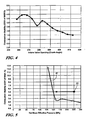
Figure 4 illustrates an exemplary combustion stability versus intake valve opening phase curve demonstrative of low load limit benefits in accordance with the method of the present invention.; and, -
Figure 5 illustrates an exemplary combustion stability versus cylinder net mean effective pressure curve demonstrative of low load limit benefits in accordance with the method of the present invention. - With reference first to
Figure 1 , an exemplary single cylinder four-stroke internal combustion engine system (engine) 10 suited for implementation of the present invention is schematically illustrated. It is to be appreciated that the present invention is equally applicable to a multi-cylinder four-stroke internal combustion engine. The presentexemplary engine 10 is shown configured for direct combustion chamber injection (direct injection) of fuel vis-à-vis fuel injector 41. Alternative fueling strategies including port fuel injection or throttle body fuel injection may also be used in the implementation of the present invention; however, the preferred approach is direct injection. Similarly, while widely available grades of gasoline and light ethanol blends thereof are preferred fuels, alternative liquid and gaseous fuels such as higher ethanol blends (e.g. E80, E85), neat ethanol (E99), neat methanol (M100), natural gas, hydrogen, biogas, various reformates, syngases etc. may also be used in the implementation of the present invention. - With respect to the base engine, a
piston 11 is movable in acylinder 13 and defines therein a variablevolume combustion chamber 15. Piston 11 is connected tocrankshaft 35 through connectingrod 33 and reciprocally drives or is reciprocally driven bycrankshaft 35.Engine 10 also includesvalve train 16 illustrated with asingle intake valve 21 and asingle exhaust valve 23 though multiple intake and exhaust valve variations are equally applicable for utilization with the present invention. Valvetrain 16 also includes valve actuation means 25 which may take any of a variety of forms including, preferably, electrically controlled hydraulic or electromechanical actuation. Alternative valve actuation means adaptable for implementation in conjunction with the present invention include multi-profile cams, cam phasers and other mechanically variable valve actuation technologies implemented individually or in combination with another.Intake passage 17 supplies air into thecombustion chamber 15. The flow of- the air into thecombustion chamber 15 is controlled byintake valve 21 during intake events. Combusted gases are expelled from thecombustion chamber 15 throughexhaust passage 19 with flow controlled byexhaust valve 23 during exhaust events. - Engine control is provided by computer based
control 27 which may take the form of conventional hardware configurations and combinations including powertrain controllers, engine controllers and digital signal processors in integrated or distributed architectures. In general,control 27 includes at least one microprocessor, ROM, RAM, and various I/O devices including A/D and D/A converters and power drive circuitry.Control 27 also specifically includes controls for valve actuation means 25 andfuel injector 41.Controller 27 includes the monitoring of a plurality of engine related inputs from a plurality of transduced sources including engine coolant temperature, outside air temperature, manifold air temperature, operator torque requests, ambient pressure, manifold pressure in throttled applications, displacement and position sensors such as for valve train and engine crankshaft quantities, and further includes the generation of control commands for a variety of actuators as well as the performance of general diagnostic functions. While illustrated and described as integral withcontroller 27, the control and power electronics associated with valve actuation means 25 andfuel injector 41 may be incorporated as part of distributed smart actuation scheme wherein certain monitoring and control functionality related to respective subsystems are implemented by programmable distributed controllers associated with such respective valve and fuel control subsystems. - Having thus described the environment and certain application hardware suitable for implementing the method of the present invention,
Figures 2 and3 are now referenced to describe the method itself. InFigure 2 , valve lifts of the intake and exhaust valves are plotted against a complete four-stroke combustion cycle. A full 720 degrees or two revolutions of the crankshaft are plotted against the horizontal axis beginning at 0 degrees corresponding to top dead center (TDC) of the piston at the beginning of the expansion stroke (end of the compression stroke) through to the same top dead center position at the end of the compression stroke (beginning of the expansion stroke). By convention and as followed herein, the crankshaftangular positions 0 through 720 refer to degrees of crankshaft rotation after top dead center combustion. The sequentially repeated cycles are delineated across the top of the Figure within double-ended arrows labeled Expansion, Exhaust, Intake and Compression. Each of these cycles correspond to the piston motion between respective ones of top dead and bottom dead center positions and covers a full 180 degrees of crankshaft rotation or one-quarter of the complete four-stroke cycle. InFigure 3 , cylinder pressures are plotted against contiguous portions of the four-stroke combustion cycle, to wit the exhaust and intake strokes as clearly evidenced by the similarly labeled double-ended arrows shown across the top of the Figure. - In the present exemplary exposition of the invention, a four-stroke, single cylinder, 0.55 liter, controlled auto-ignition , gasoline fueled internal combustion engine was utilized in implementing the various valve controls and acquisition of the various data embodied herein. Unless specifically discussed otherwise, all such implementations and acquisitions are assumed to be carried out under standard conditions as understood by one having ordinary skill in the art.
- In accordance with the present invention a low pressure event is established within the combustion chamber, preferably by means of phase control over the opening and closing of one or more of the intake and exhaust valves. In the present example illustrated in
Figures 2 and3 , it is assumed that an exhaust event is caused to occur wherein the exhaust valve is opened for at least a portion of the exhaust stroke from 180 to 360 degrees. The actual opening and closing angles of the exhaust valve during an exhaust event will vary in accordance with such factors as engine speed and exhaust runner geometries as well as other desired engine tuning characteristics. In the present illustrated example the exhaust valve closure is assumed to correspond substantially to 380 degrees or 20 degrees after exhaust stroke TDC. Preferably, the exhaust valve closure occurs within approximately 20 degrees before exhaust stroke TDC to 20 degrees after exhaust stroke TDC. It is generally believed that maximum expulsion of exhaust gases from the combustion chamber will aid in minimizing residual cylinder pressure and such condition is generally consistent with effectuating deeper and longer duration low pressure events. Through certain gas dynamics under certain conditions maximum expulsion occurs when the exhaust valve remains open for some angle after exhaust stroke TDC. More preferably, then, the exhaust valve closure occurs within approximately exhaust stroke TDC to 20 degrees after exhaust stroke TDC. - Consistent with the objective of establishing a low pressure event within the combustion chamber during the intake stroke it may further be desirable that the exhaust event exhaust valve closure absolute phase relative to exhaust stroke TDC is not greater than the intake valve opening phase after exhaust stroke TDC or that minimal valve overlap exists. Generally a certain degree of asymmetry around exhaust stroke TDC as between exhaust valve closure and intake valve opening as described is required in order to establish the desired low pressure conditions within the combustion chamber. If exhaust event exhaust valve closure occurs before exhaust stroke TDC, then it may be desirable to allow at least a similar angle after TDC for the pressure in the combustion chamber to relax before the intake valve begins to open. Preferably, the intake valve opening follows the exhaust valve closing at about 20 to about 60 degrees after exhaust stroke TDC.
- In accordance with another feature of the present invention the exhaust valve is opened during at least a portion of the intake event to recirculate or rebreathe combusted gases by drawing them back into the combustion chamber vis-à-vis the exhaust valve. Preferably, this rebreathe event exhaust valve opening occurs subsequent to the opening of the intake valve and more preferably occurs about 10 to about 30 degrees after the intake valve opening. Additionally, the exhaust valve closing associated with this rebreathe event preferably occurs prior to the intake valve closure. And more preferably, this exhaust valve closure occurs about 10 to about 40 degrees prior to the intake valve closure.
- The rebreathe event exhaust valve opening is also preferably characterized by a relatively high valve lift. More preferably such valve lift is no greater than about 50 % of maximum valve lift.
- The general and preferred intake and exhaust valve phasings heretofore described are substantially set forth in the exemplary curves illustrated in
Figure 2 .Curve 50 represents an exhaust event exhaust valve profile wherein valve closure occurs at substantially 20 degrees after exhaust stroke TDC. For purposes of exposition it is assumed that the exhaust event is substantially static with respect to exhaust event exhaust valve closure phasing although, as described previously, it is contemplated that in fact phase shifting of the exhaust valve closure is within the scope of the invention in attaining various outcomes and objectives thereof. Intake profiles 51 and 53 corresponding respectively to early (about 12 degrees after exhaust stroke TDC or 372 degrees) and late (about 52 degrees after exhaust stroke TDC or 412 degrees) intake valve openings, both of which intake profiles also illustrate substantial convergence of the intake valve closings at about 60 degrees after intake stroke bottom dead center (BDC). Rebreathe profiles 52 and 54 correlate respectively to the early and late intake valve opening profiles 51 and 53 and each corresponds to a rebreathe event exhaust valve opening initiated at about 30 degrees after the respective correlated intake valve opening. Rebreathe profiles 52 and 54 also illustrate substantial convergence of the rebreathe event exhaust valve closings at about 40 degrees prior to the intake valve closure. If a continuum of such correlated intake and rebreathe profiles were plotted in the Figure with intake valve openings between 372 and 412 degrees and respective correlated rebreathe openings lagging by about 30 degrees, the result would be increasing vacuum levels and durations thereof within the combustion chamber. Of course, in addition to the various low pressure profiles within the combustion chamber which can be achieved with simply phase shifting valve openings as described, additional pressure profiles may be achieved through more complex and independent variations of the exhaust, intake and rebreathe profiles including by way of lift variation in addition to timing. It should be noted also that significant variations in gas constituent mixtures and temperature can also be effected by way of the complex variations of the exhaust, intake and rebreathe profiles that are possible. The operation of the engine as exhibited by the exemplary Figures herein is, as indicated earlier, as a controlled auto-ignition engine. - The valve phase controls to establish a low pressure event within the combustion chamber are carried out to establish pressure level depressions and durations thereof within the combustion chamber that are not found in conventional known four-stroke operation. With reference now to
Figure 3 , pressure profiles resulting from the exemplary valve profiles described with respect toFigure 2 are illustrated. Therein, a family of curves is generally designated by the numeral 61 and is illustrated with respect to 360 degrees of crankshaft rotation, to wit through the exhaust and intake strokes of the complete four-stroke process only as delineated across the top of the Figure within double-ended arrows labeled Exhaust and Intake. Each curve substantially corresponds to a respective intake valve opening at 5 degree increments beginning at 372 degrees and ending at 412 degrees and a corresponding exhaust valve opening lagging the respective intake valve opening by substantially 30 degrees. Cylinder pressure is illustrated on a relative linear scale along the vertical axis with ambient pressure being specifically labeled and assumed to be substantially one standard atmosphere or about 101 kPa. Consistent with the simplified assumption respecting the exhaust event exhaust valve closing at a fixed phase of substantially 20 degrees after exhaust stroke TDC for all of the various intake valve/exhaust event exhaust valve openings, the pressure profiles through about 400 degrees (40 degrees past exhaust stroke TDC) are substantially equivalent.Region 63 generally designates the area of resultant low pressure events or sub-atmospheric pressure conditions established in accordance with the present invention. A first relatively shallow and limited duration low pressure event is sub-atmospheric from substantially just prior to 390 degrees to substantially just after 435 degrees or 75 degrees past exhaust stroke TDC. A second relatively deep and lasting duration low pressure event is sub-atmospheric from substantially just prior to 390 degrees to substantially just prior to 480 degrees. The first low pressure event reaches substantially 42 kPa below ambient or sub-atmospheric or alternatively stated about 42% below ambient or atmospheric or about 58% of ambient or atmospheric. The second low pressure event reaches substantially 75 kPa below ambient or sub-atmospheric or alternatively stated about 75% below ambient or atmospheric or about 25% of ambient or atmospheric. The specific curves illustrated inFigure 3 are, of course, exemplary with other such curves and profiles being able to be established by virtue of more complex and independent variations of the exhaust, intake and rebreathe profiles including by way of lift variation in addition to timing. For example, further retarding the intake valve opening would effectuate deeper low pressure events. Similarly, deeper low pressure events may be effectuated by retarding further the opening of the rebreathe event exhaust valve opening from the intake valve opening or eliminating a rebreathe event altogether. Where it is desirable to maintain some exhaust gas recirculation, adapting the exhaust event exhaust valve closure may provide an alternative to rebreathe or external exhaust gas recirculation means may be employed to ensure ingestion of combusted gases together with fresh air through the intake valve. - The fueling methodology for an engine operated as described may be selected from any variety of methods. Liquid and gaseous injections are candidates as are TBI, MPFI and DI. Additionally, it is contemplated that single pulse, split pulse, air assisted and other types of delivery may be employed. Also, the type of ignition system employable is variable and includes such non-limiting examples as SI, CI, and controlled auto-ignition.
- The impact of current invention on the low load limit of the exemplary controlled auto-ignition engine operation is shown in
Figure 4 . Without using the current invention, the low load limit of the exemplary -- and most typical -- four-stroke direct-injection auto-ignition gasoline engine is around 225 kPa Net Mean Effective Pressure (NMEP) with 5 % Coefficient of Variation of Indicated Mean Effective Pressure (COV of IMEP) as an indicator. The data plotted inFigure 4 was acquired with leaned out fueling to substantially 175 kPa NMEP and with implementation of the exemplary intake and exhaust valve profiles heretofore described. The plot of line 71 clearly shows combustion stability improvement with the introduction and expansion of low-pressure events within the combustion chamber as described herein. The clear conclusion drawn is that expanding the sub-atmospheric pressure conditions improves combustion stability and allows the engine to be operated at lower load limits.Figure 5 is demonstrative of the same clear benefits and advantages of implementing the present invention on a normalized scale of NMEP within the combustion chamber relative to ambient. In that Figure,point 83 represents the low load limit of substantially 225 kPa in terms of NMEP with 5 % COV of IMEP as the indicator. Points to the left in the Figure (i.e. lower NMEPs) correspond to lower loads. The plot ofline 81 clearly shows significantly less NMEPs before the acceptable 5% or less COV of IMEP is reached, effectively moving the low load limit point to about 150 kPa NMEP The present invention has been described with respect to certain preferred embodiments and variations herein. Other alternative embodiments, variations ad implementations may be implemented and practiced without departing from the scope of the invention which is to be limited only by the claims as follow:
Claims (9)
- Method of operating a four-stroke internal combustion engine (10) including a variable volume combustion chamber (15) defined by a piston (11) reciprocating within a cylinder (13) between top-dead center and bottom-dead center points and an intake valve (21) and an exhaust valve (23) controlled during repetitive, sequential exhaust, intake, compression and expansion strokes of said piston (11) comprising:providing an exhaust event during which the exhaust valve (23) is open for expelling combusted gases from the combustion chamber (15);subsequent to the exhaust event, providing a period of simultaneous closure of the exhaust and intake valves (23, 21) during at least a portion of the intake stroke of the piston (11) effective to establish a sub-atmospheric pressure condition within the combustion chamber (15);providing an intake event during which the intake valve (21) is open for ingesting fresh air into the combustion chamber (15); andproviding a rebreathe event wherein said exhaust valve (23) is open during at least a portion of the intake event;characterized in thatsaid rebreathe event is initiated subsequent to initiation of said intake event and terminated prior to termination of said intake event;wherein said exhaust valve (23) is lifted no more than 50% of maximum valve lift during said rebreathe event.
- Method of operating a four-stroke internal combustion engine as claimed in claim 1 wherein said sub-atmospheric pressure condition within the combustion chamber (15) reaches at least about 42 kPa sub-atmospheric.
- Method of operating a four-stroke internal combustion engine as claimed in claim 1 wherein said sub-atmospheric pressure condition within the combustion chamber (15) terminates not earlier than about 75 degrees past exhaust stroke top dead center.
- Method of operating a four-stroke internal combustion engine as claimed in claim 1 wherein said sub-atmospheric pressure condition within the combustion chamber (15) reaches at least about 42 kPa sub-atmospheric and terminates not earlier than about 75 degrees past exhaust stroke top dead center.
- Method of operating a four-stroke internal combustion engine as claimed in claim 1 wherein said rebreathe event is initiated about 10 to about 30 degrees subsequent to initiation of said intake event.
- Method of operating a four-stroke internal combustion engine as claimed in claim 5 wherein said intake event is initiated about 20 to about 60 degrees after exhaust stroke top dead center.
- Method of operating a four-stroke internal combustion engine as claimed in claim 1 wherein said rebreathe event is terminated about 10 to about 40 degrees prior to termination of said intake event.
- Method of operating a four-stroke internal combustion engine as claimed in claim 7 wherein said intake event terminates about 20 to about 60 degrees after intake stroke bottom dead center.
- Method of operating a four-stroke internal combustion engine as claimed in claim 5 wherein said intake event is initiated about 20 to about 60 degrees after exhaust stroke top dead center and is terminated about 20 to about 60 degrees after intake stroke bottom dead center, and said rebreathe event is initiated about 10 to about 30 degrees subsequent to initiation of said intake event and is terminated about 10 to about 40 degrees prior to the termination of said intake event.
Applications Claiming Priority (2)
| Application Number | Priority Date | Filing Date | Title |
|---|---|---|---|
| US10/611,845 US7004124B2 (en) | 2003-07-01 | 2003-07-01 | Valve strategy for operating a controlled auto-ignition four-stroke internal combustion engine |
| US611845 | 2003-07-01 |
Publications (3)
| Publication Number | Publication Date |
|---|---|
| EP1493906A2 EP1493906A2 (en) | 2005-01-05 |
| EP1493906A3 EP1493906A3 (en) | 2010-01-13 |
| EP1493906B1 true EP1493906B1 (en) | 2012-03-07 |
Family
ID=33435445
Family Applications (1)
| Application Number | Title | Priority Date | Filing Date |
|---|---|---|---|
| EP04014737A Active EP1493906B1 (en) | 2003-07-01 | 2004-06-23 | Valve strategy for operating a controlled auto-ignition four-stroke internal combustion engine |
Country Status (2)
| Country | Link |
|---|---|
| US (1) | US7004124B2 (en) |
| EP (1) | EP1493906B1 (en) |
Families Citing this family (10)
| Publication number | Priority date | Publication date | Assignee | Title |
|---|---|---|---|---|
| US7080613B2 (en) * | 2004-07-12 | 2006-07-25 | General Motors Corporation | Method for auto-ignition combustion control |
| US7150250B2 (en) * | 2004-07-26 | 2006-12-19 | General Motors Corporation | Valve and fueling strategy for operating a controlled auto-ignition four-stroke internal combustion engine |
| DE112005001796B4 (en) | 2004-07-26 | 2018-12-13 | General Motors Corp. | A method of controlling a four-stroke internal combustion engine with controlled auto-ignition |
| US7152559B2 (en) * | 2004-07-26 | 2006-12-26 | General Motors Corporation | Valve and fueling strategy for operating a controlled auto-ignition four-stroke internal combustion engine |
| US7128047B2 (en) * | 2004-07-26 | 2006-10-31 | General Motors Corporation | Valve and fueling strategy for operating a controlled auto-ignition four-stroke internal combustion engine |
| JP3882838B2 (en) * | 2005-02-04 | 2007-02-21 | いすゞ自動車株式会社 | Diesel engine exhaust valve control method and exhaust valve control device |
| US7367319B2 (en) * | 2005-11-16 | 2008-05-06 | Gm Global Technology Operations, Inc. | Method and apparatus to determine magnitude of combustion chamber deposits |
| US7832370B2 (en) * | 2006-11-16 | 2010-11-16 | Gm Global Technology Operations, Inc. | Low-load operation extension of a homogeneous charge compression ignition engine |
| FR2933449B1 (en) * | 2008-07-03 | 2010-07-30 | Inst Francais Du Petrole | PROCESS FOR IMPROVING THE VAPORIZATION OF A UTLISE FUEL FOR AN INTERNAL COMBUSTION ENGINE, IN PARTICULAR DIRECT INJECTION, IN PARTICULAR SELF-LIGHTING AND ESPECIALLY DIESEL TYPE |
| US11585284B1 (en) * | 2021-07-29 | 2023-02-21 | Ford Global Technologies, Llc | Methods for re-combustion in engines |
Family Cites Families (24)
| Publication number | Priority date | Publication date | Assignee | Title |
|---|---|---|---|---|
| US3714932A (en) * | 1971-08-19 | 1973-02-06 | Eaton Yale & Towne | Emissions control system |
| US4350129A (en) * | 1976-10-01 | 1982-09-21 | Nissan Motor Company, Limited | Spark-ignition internal combustion engine capable of preventing noxious gas emissions |
| US4446830A (en) | 1983-01-10 | 1984-05-08 | Ford Motor Company | Method of operating an engine with a high heat of vaporization fuel |
| US4703734A (en) * | 1985-03-06 | 1987-11-03 | Nissan Motor Co., Ltd. | Multi-valve internal combustion engine |
| DE3716947C1 (en) * | 1987-05-20 | 1988-03-03 | Bayerische Motoren Werke Ag | Charge exchange process for a 4-stroke reciprocating piston internal combustion engine |
| JP3357384B2 (en) * | 1991-08-27 | 2002-12-16 | マツダ株式会社 | Spark ignition type reciprocating engine |
| US5623904A (en) * | 1995-05-16 | 1997-04-29 | Yamaha Hatsudoki Kabushiki Kaisha | Air-assisted fuel injection system |
| US20010045194A1 (en) * | 1998-04-02 | 2001-11-29 | Takuya Shiraishi | Internal combustion engine control system |
| JPH09250387A (en) * | 1996-03-19 | 1997-09-22 | Toyota Motor Corp | Fuel injection control method for internal combustion engine |
| WO1997044580A1 (en) * | 1996-05-20 | 1997-11-27 | Borg-Warner Automotive, Inc. | Automotive fluid control system with pressure balanced solenoid valve |
| FR2760487B1 (en) | 1997-03-07 | 1999-04-30 | Inst Francais Du Petrole | METHOD FOR CONTROLLING SELF-IGNITION IN A 4-STROKE ENGINE |
| US5713328A (en) | 1997-03-31 | 1998-02-03 | Ford Global Technologies, Inc. | Spark ignited internal combustion engine with multiple event fuel injection |
| JP3355997B2 (en) * | 1997-05-30 | 2002-12-09 | 株式会社日立製作所 | Internal combustion engine control method |
| JP3459339B2 (en) * | 1997-07-03 | 2003-10-20 | 株式会社リコー | Modulation circuit, demodulation circuit and modulation / demodulation circuit system employing PPM method |
| EP0983433B1 (en) * | 1998-02-23 | 2007-05-16 | Cummins Inc. | Premixed charge compression ignition engine with optimal combustion control |
| JP4326044B2 (en) * | 1998-08-21 | 2009-09-02 | 日産自動車株式会社 | 4-cycle internal combustion engine |
| JP2000073800A (en) * | 1998-08-28 | 2000-03-07 | Hitachi Ltd | Controller for engine with electromagnet drive suction and exhaust valve |
| JP3994586B2 (en) * | 1999-07-12 | 2007-10-24 | トヨタ自動車株式会社 | Valve driving device for internal combustion engine |
| JP4253426B2 (en) * | 1999-09-14 | 2009-04-15 | 日産自動車株式会社 | Compression self-ignition gasoline engine |
| WO2001046572A1 (en) | 1999-12-22 | 2001-06-28 | Lotus Cars Limited | A four stroke engine |
| JP4406989B2 (en) * | 2000-02-22 | 2010-02-03 | トヨタ自動車株式会社 | Valve characteristic control device for internal combustion engine |
| US6439210B1 (en) * | 2000-07-12 | 2002-08-27 | Caterpillar Inc. | Exhaust gas reprocessing/recirculation with variable valve timing |
| JP4517515B2 (en) * | 2001-02-14 | 2010-08-04 | マツダ株式会社 | 4-cycle engine for automobiles |
| AT5300U1 (en) * | 2001-09-06 | 2002-05-27 | Avl List Gmbh | METHOD FOR OPERATING AN INTERNAL COMBUSTION ENGINE |
-
2003
- 2003-07-01 US US10/611,845 patent/US7004124B2/en not_active Expired - Lifetime
-
2004
- 2004-06-23 EP EP04014737A patent/EP1493906B1/en active Active
Also Published As
| Publication number | Publication date |
|---|---|
| US20050000478A1 (en) | 2005-01-06 |
| EP1493906A2 (en) | 2005-01-05 |
| EP1493906A3 (en) | 2010-01-13 |
| US7004124B2 (en) | 2006-02-28 |
Similar Documents
| Publication | Publication Date | Title |
|---|---|---|
| US7021277B2 (en) | Valve and fueling strategy for operating a controlled auto-ignition four-stroke internal combustion engine | |
| US7152559B2 (en) | Valve and fueling strategy for operating a controlled auto-ignition four-stroke internal combustion engine | |
| US7128047B2 (en) | Valve and fueling strategy for operating a controlled auto-ignition four-stroke internal combustion engine | |
| US7228839B2 (en) | NOx emission control for a controlled auto-ignition four-stroke internal combustion engine | |
| WO2006023003A2 (en) | Valve and fueling strategy for operating a controlled auto-ignition four-stroke internal combustion engine | |
| EP1505289B1 (en) | Injection strategy for operating a direct-injection controlled auto-ignition four-stroke internal combustion engine | |
| US7275514B2 (en) | Method of HCCI and SI combustion control for a direct injection internal combustion engine | |
| US7337762B2 (en) | Fuel adaptation in a homogeneous charge compression ignition engine | |
| US7478620B2 (en) | Method and apparatus to control a transition between HCCI and SI combustion in a direct-injection gasoline engine | |
| US7684925B2 (en) | Engine warm-up of a homogeneous charge compression ignition engine | |
| US7080613B2 (en) | Method for auto-ignition combustion control | |
| US5927238A (en) | Valve timing for four stroke internal combustion engines | |
| US8290686B2 (en) | Method for controlling combustion mode transitions for an internal combustion engine | |
| US7966991B2 (en) | Method and apparatus for controlling combustion mode transitions in an internal combustion engine | |
| WO2008130787A1 (en) | Method and apparatus for selecting a combustion mode for an internal combustion engine | |
| US10240491B2 (en) | Control system of engine | |
| US7263982B2 (en) | Method for operating and internal combustion engine | |
| EP1493906B1 (en) | Valve strategy for operating a controlled auto-ignition four-stroke internal combustion engine |
Legal Events
| Date | Code | Title | Description |
|---|---|---|---|
| PUAI | Public reference made under article 153(3) epc to a published international application that has entered the european phase |
Free format text: ORIGINAL CODE: 0009012 |
|
| AK | Designated contracting states |
Kind code of ref document: A2 Designated state(s): AT BE BG CH CY CZ DE DK EE ES FI FR GB GR HU IE IT LI LU MC NL PL PT RO SE SI SK TR |
|
| AX | Request for extension of the european patent |
Extension state: AL HR LT LV MK |
|
| PUAL | Search report despatched |
Free format text: ORIGINAL CODE: 0009013 |
|
| AK | Designated contracting states |
Kind code of ref document: A3 Designated state(s): AT BE BG CH CY CZ DE DK EE ES FI FR GB GR HU IE IT LI LU MC NL PL PT RO SE SI SK TR |
|
| AX | Request for extension of the european patent |
Extension state: AL HR LT LV MK |
|
| RIC1 | Information provided on ipc code assigned before grant |
Ipc: F02M 25/07 20060101ALI20091205BHEP Ipc: F02D 13/02 20060101ALI20091205BHEP Ipc: F01L 1/46 20060101ALI20091205BHEP Ipc: F02B 41/00 20060101ALI20091205BHEP Ipc: F02B 75/02 20060101AFI20040915BHEP |
|
| 17P | Request for examination filed |
Effective date: 20100709 |
|
| AKX | Designation fees paid |
Designated state(s): DE |
|
| 17Q | First examination report despatched |
Effective date: 20100823 |
|
| RAP1 | Party data changed (applicant data changed or rights of an application transferred) |
Owner name: GM GLOBAL TECHNOLOGY OPERATIONS, INC. |
|
| RAP1 | Party data changed (applicant data changed or rights of an application transferred) |
Owner name: GM GLOBAL TECHNOLOGY OPERATIONS, INC. |
|
| RAP1 | Party data changed (applicant data changed or rights of an application transferred) |
Owner name: GM GLOBAL TECHNOLOGY OPERATIONS LLC |
|
| GRAJ | Information related to disapproval of communication of intention to grant by the applicant or resumption of examination proceedings by the epo deleted |
Free format text: ORIGINAL CODE: EPIDOSDIGR1 |
|
| GRAP | Despatch of communication of intention to grant a patent |
Free format text: ORIGINAL CODE: EPIDOSNIGR1 |
|
| GRAS | Grant fee paid |
Free format text: ORIGINAL CODE: EPIDOSNIGR3 |
|
| GRAA | (expected) grant |
Free format text: ORIGINAL CODE: 0009210 |
|
| AK | Designated contracting states |
Kind code of ref document: B1 Designated state(s): DE |
|
| REG | Reference to a national code |
Ref country code: DE Ref legal event code: R096 Ref document number: 602004036760 Country of ref document: DE Effective date: 20120503 |
|
| PLBE | No opposition filed within time limit |
Free format text: ORIGINAL CODE: 0009261 |
|
| STAA | Information on the status of an ep patent application or granted ep patent |
Free format text: STATUS: NO OPPOSITION FILED WITHIN TIME LIMIT |
|
| 26N | No opposition filed |
Effective date: 20121210 |
|
| REG | Reference to a national code |
Ref country code: DE Ref legal event code: R097 Ref document number: 602004036760 Country of ref document: DE Effective date: 20121210 |
|
| PGFP | Annual fee paid to national office [announced via postgrant information from national office to epo] |
Ref country code: DE Payment date: 20230523 Year of fee payment: 20 |