EP1493870A1 - Working machine - Google Patents
Working machine Download PDFInfo
- Publication number
- EP1493870A1 EP1493870A1 EP04103073A EP04103073A EP1493870A1 EP 1493870 A1 EP1493870 A1 EP 1493870A1 EP 04103073 A EP04103073 A EP 04103073A EP 04103073 A EP04103073 A EP 04103073A EP 1493870 A1 EP1493870 A1 EP 1493870A1
- Authority
- EP
- European Patent Office
- Prior art keywords
- window
- cover
- guard cover
- locking mechanism
- guard
- Prior art date
- Legal status (The legal status is an assumption and is not a legal conclusion. Google has not performed a legal analysis and makes no representation as to the accuracy of the status listed.)
- Withdrawn
Links
- 230000007246 mechanism Effects 0.000 claims abstract description 48
- 238000012423 maintenance Methods 0.000 claims abstract description 36
- 230000002093 peripheral effect Effects 0.000 claims abstract description 4
- 239000000446 fuel Substances 0.000 description 2
- 238000000034 method Methods 0.000 description 1
- 238000006467 substitution reaction Methods 0.000 description 1
Images


Classifications
-
- E—FIXED CONSTRUCTIONS
- E02—HYDRAULIC ENGINEERING; FOUNDATIONS; SOIL SHIFTING
- E02F—DREDGING; SOIL-SHIFTING
- E02F9/00—Component parts of dredgers or soil-shifting machines, not restricted to one of the kinds covered by groups E02F3/00 - E02F7/00
- E02F9/08—Superstructures; Supports for superstructures
- E02F9/0858—Arrangement of component parts installed on superstructures not otherwise provided for, e.g. electric components, fenders, air-conditioning units
- E02F9/0891—Lids or bonnets or doors or details thereof
-
- B—PERFORMING OPERATIONS; TRANSPORTING
- B62—LAND VEHICLES FOR TRAVELLING OTHERWISE THAN ON RAILS
- B62D—MOTOR VEHICLES; TRAILERS
- B62D25/00—Superstructure or monocoque structure sub-units; Parts or details thereof not otherwise provided for
- B62D25/08—Front or rear portions
- B62D25/10—Bonnets or lids, e.g. for trucks, tractors, busses, work vehicles
-
- E—FIXED CONSTRUCTIONS
- E02—HYDRAULIC ENGINEERING; FOUNDATIONS; SOIL SHIFTING
- E02F—DREDGING; SOIL-SHIFTING
- E02F3/00—Dredgers; Soil-shifting machines
- E02F3/04—Dredgers; Soil-shifting machines mechanically-driven
- E02F3/28—Dredgers; Soil-shifting machines mechanically-driven with digging tools mounted on a dipper- or bucket-arm, i.e. there is either one arm or a pair of arms, e.g. dippers, buckets
- E02F3/30—Dredgers; Soil-shifting machines mechanically-driven with digging tools mounted on a dipper- or bucket-arm, i.e. there is either one arm or a pair of arms, e.g. dippers, buckets with a dipper-arm pivoted on a cantilever beam, i.e. boom
- E02F3/32—Dredgers; Soil-shifting machines mechanically-driven with digging tools mounted on a dipper- or bucket-arm, i.e. there is either one arm or a pair of arms, e.g. dippers, buckets with a dipper-arm pivoted on a cantilever beam, i.e. boom working downwardly and towards the machine, e.g. with backhoes
- E02F3/325—Backhoes of the miniature type
Definitions
- the present invention relates to a working machine such as a hydraulic excavator including a guard cover, which covers pieces of apparatus.
- an upper rotating body of a hydraulic excavator are disposed pieces of apparatus such as a working oil tank, a radiator, a main control valve, a multi control valve and a selector valve and the like. These are covered with a guard cover, and the maintenance of the apparatus or the like in the cover is performed by opening the cover.
- the guard cover is large and heavy, its opening and closing are troublesome and further a space required for opening and closing the cover is large.
- a technology that an openable small window is provided in the cover and the apparatus or the like, which require daily maintenance, are provided in the guard cover so as to face this small window has been known (see Japanese Patent Laid-Open Publication No. Hei. 10-219741).
- both locking mechanisms each require a key cylinder and a locking mechanism enough to satisfy at least safety standards.
- the object of the present invention is to provide a working machine, which can simplify a locking mechanism for a guard cover and in which the guard cover is difficult to be opened by unauthorized persons.
- the working machine according to the present invention has the following basic configurations.
- the working machine includes an openable guard cover attached to an outer peripheral portion of main body of the working machine, which has a window for performing maintenance of apparatus and covers the apparatus; a window cover provided with this guard cover for opening and closing the window; and a guard cover locking mechanism provided within the guard cover, which locks the guard cover in a closed mode.
- This guard cover locking mechanism allows a locking operation and an unlocking operation from the outside of the guard cover through the window.
- a guard cover including a locking mechanism, which is locking/unlocking operated is provided with the window, which is opened and closed by the window cover and a locking mechanism for the guard cover is provided inside the window, only after the window is opened the entire guard cover can be opened. Therefore, if a locking mechanism for the window cover, which satisfies the safety standards, is used, a simplified locking mechanism for the guard cover may be used.
- the locking mechanism for the guard cover is a kind of key concealed within the window cover, and the guard cover is difficult to be opened by unauthorized persons. Thus, the possibility of operating inner apparatus without authorized persons' permission becomes low.
- a hydraulic excavator is illustrated as an application object.
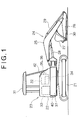
- a base machine 23 is formed in such a manner that an upper rotating body 22 is rotatably mounted on a crawler type lower traveling body 21 around its vertical shaft, as shown in Fig. 1.
- a working attachment 24 comprising a boom 25, an arm 26, a bucket 27, hydraulic cylinders 28, 29, 30 which operate them, and a swing cylinder (not shown), which swings the entire attachment in opposite directions.
- a working oil tank 32, a radiator 33, a main control valve 34, which controls the operation of each hydraulic actuator, a multi control valve 35, which changes the relationships between a lever, which is operated in accordance with the kinds of working attachment 24 and an operator's choice, and an actuator, which is moved, and a selector valve 36, which changes oil flow in accordance with the kinds of the working attachment 24 and the like, are disposed.
- a guard cover 37 covers these apparatus.
- a reference numeral 38 denotes an engine, and 39 a hydraulic pump.
- a rear end side of the guard cover 37 is rotatably attached to the upper rotating body 22 in an openable manner by a hinge 40 (shown in Fig. 2).
- the guard cover 37 is locked and unlocked by a guard cover locking mechanism (described later) provided on its front end side.
- a window 41 which is an elongated rectangle on a front side of the machine in an open mode, as shown in Fig. 2 or later.
- This window 41 is opened and closed by a window cover 42.
- This window cover 42 is rotatably attached to the guard cover 37 (an opening edge portion of the window 41) with a hinge 43 (see Figs. 4 and 5) in an openable manner on one side of the window cover 42. Then, this window cover 42 is opened to perform daily maintenance, and other maintenance is performed by opening the guard cover 37.
- the apparatus or the like covered with the guard cover 37 are separated to high frequency maintenance apparatus, which require substantially daily maintenance, and other low frequency maintenance apparatus which do not always require daily maintenance.
- a level gauge 32a shown in Figs. 4 and 5) of the working oil tank 32, the main control valve 34, the multi control valve 35 and the selector valve 36 are included. These apparatus are disposed in a front portion facing the window 41. Namely, the high frequency maintenance apparatus are disposed in such a manner that the maintenance of them can be performed through the window.
- the high frequency maintenance apparatus are attached to an outer wall surface of the working oil tank 32.
- the main control valve 34 is attached to a side of the working oil tank 32, and the multi control valve 35 and the selector valve 36 are attached to a front surface of the tank 32, respectively.
- the low frequency maintenance apparatus are disposed in other vacant space appropriately and maintenance thereof is performed by opening the entire guard cover 37 if necessary.
- the window cover 42 is locked in the closed mode by a key open and close type window cover locking mechanism 44 provided with a key hole on a front surface of the window cover 42, and is unlocked by key's rotary operation.
- the window cover locking mechanism 44 locks the window cover 42 in the locked mode and unlocks it in an unlocked mode by the cover 37's key operation from the outside.
- window cover locking mechanism 44 as shown in drawings, ones having a configuration that a tongue piece key lever is engaged/disengaged with the inside of a lower side edge of the window 41 by a key operation and having a configuration that a rod is extended and retracted by a key operation to engage/disengage the lever with a side edge inside of the window 41, can be used.
- a guard cover locking mechanism 45 which locks the guard cover 37 in a locked mode, comprises an elongated ring-shaped fastener 46 provided in a lower side edge of the window 41 in the guard cover 37 so as to be operated from the outside, a catch 47, provided on the upper rotating body 22 side in accordance with this fastener 46.
- the fastener 46 is hooked on the catch 47 to be tensed so that the guard cover 37 is locked in the closed mode.
- the fastener 46 is released from the catch 47 to be unlocked.
- guard cover locking mechanism 45 may be locked/unlocked by manual operation, or a bolt key or the like can be also used.
- the maintenance of the high frequency maintenance apparatus (the level gauge 32a of the working oil tank 32, the main control valve 34, the multi control valve 35, the selector valve 36) can be easily performed by opening only the window cover 42 as described above.
- the high frequency maintenance apparatus including at least one of the selector valve 36, the multi control valve 35, and the level gauge 32a of the working oil tank 32 are disposed in conditions where they can be maintained through the window 41.
- the facility of maintenance due to provision of the window 41 which is an essential object, can be ensured.
- the guard cover locking mechanism 45 is provided in an inner side edge of the window 41 in conditions where it is seen from an opened window 41.
- the mechanism 45 may be located within a visible scope through the window 41 in an open mode.
- the window cover 42 is first opened.
- the guard cover locking mechanism 45 positioned at a lower side edge of the window 41, is seen from the outside as shown in Fig. 4, and is operable.
- the entire guard cover 37 may be opened as shown in Fig. 5.
- the guard cover locking mechanism 45 is seen from the outside of the guard cover 37 in a condition that the window cover 42 is opened, and the presence of the guard cover 37 can be found at a glance, an inexperienced worker cannot be bewildered.
- the window cover locking mechanism 44 can take a simple structure, which does not use a locking key.
- the structure of the window cover locking mechanism 44 is simplified and the working machine of the present invention is advantageous in points of the production steps, cost and appearance of the machine.
- guard cover locking mechanism 45 is concealed by the window cover 42, it provides for a kind of concealed key, which cannot be seen or unlocked from the outside.
- this invention can prevent unauthorized persons from opening the guard cover 37 freely, and the possibility of operating inner apparatus without authorized persons' permission becomes low.
Landscapes
- Engineering & Computer Science (AREA)
- Mechanical Engineering (AREA)
- Mining & Mineral Resources (AREA)
- Civil Engineering (AREA)
- General Engineering & Computer Science (AREA)
- Structural Engineering (AREA)
- Chemical & Material Sciences (AREA)
- Combustion & Propulsion (AREA)
- Transportation (AREA)
- Component Parts Of Construction Machinery (AREA)
Abstract
Description
- The present invention relates to a working machine such as a hydraulic excavator including a guard cover, which covers pieces of apparatus.
- In an upper rotating body of a hydraulic excavator are disposed pieces of apparatus such as a working oil tank, a radiator, a main control valve, a multi control valve and a selector valve and the like. These are covered with a guard cover, and the maintenance of the apparatus or the like in the cover is performed by opening the cover.
- In this case, the guard cover is large and heavy, its opening and closing are troublesome and further a space required for opening and closing the cover is large. Thus, a technology that an openable small window is provided in the cover and the apparatus or the like, which require daily maintenance, are provided in the guard cover so as to face this small window, has been known (see Japanese Patent Laid-Open Publication No. Hei. 10-219741).
- Since the hydraulic excavator can be often left at the site after the completion of working, an openable locking mechanism by a key is provided in the cover so that the apparatus or the like are not operated freely by unauthorized persons. Further, in the case of providing the small window, a cover for opening and closing this small window is needed and use of the same locking mechanism in this small cover is also needed.
- Namely, two sorts of locking mechanisms for the guard cover and the small window cover are required.
- Here, if a key for both locking mechanisms is used in common, only one key is all that is required. However, the both locking mechanisms each require a key cylinder and a locking mechanism enough to satisfy at least safety standards.
- Further, to attach a key cylinder a key-operating portion for the cylinder must be fixed to the guard cover. Thus, working for the cover is needed. The working machine of the related art has been disadvantageous in the points of the production steps, cost and appearance of the machine.
- It is noted that even if another locking mechanism such as a card open-close type, a dial key or the like is used, it is not changed that two sorts of independent locking mechanisms are required.
- Further, since the position of a locking mechanism of the guard cover and its open-close method can be seen from the outside easily by a key hole or the like, there was a problem that the possibility of breaking the locking by unauthorized persons is high.
- The object of the present invention is to provide a working machine, which can simplify a locking mechanism for a guard cover and in which the guard cover is difficult to be opened by unauthorized persons.
- The working machine according to the present invention has the following basic configurations.
- Namely, the working machine includes an openable guard cover attached to an outer peripheral portion of main body of the working machine, which has a window for performing maintenance of apparatus and covers the apparatus; a window cover provided with this guard cover for opening and closing the window; and a guard cover locking mechanism provided within the guard cover, which locks the guard cover in a closed mode. This guard cover locking mechanism allows a locking operation and an unlocking operation from the outside of the guard cover through the window.
- According to the present invention, since a guard cover including a locking mechanism, which is locking/unlocking operated, is provided with the window, which is opened and closed by the window cover and a locking mechanism for the guard cover is provided inside the window, only after the window is opened the entire guard cover can be opened. Therefore, if a locking mechanism for the window cover, which satisfies the safety standards, is used, a simplified locking mechanism for the guard cover may be used.
- Thus the structure of the locking mechanism for the guard cover is simplified and the working machine of the present invention is advantageous in points of the production steps, cost of the machine, and for aesthetic purposes.
- Further, the locking mechanism for the guard cover is a kind of key concealed within the window cover, and the guard cover is difficult to be opened by unauthorized persons. Thus, the possibility of operating inner apparatus without authorized persons' permission becomes low.
-
- Fig. 1 is a schematic side view of the entire hydraulic excavator according to the present invention;
- Fig. 2 is a plan view showing an arrangement of an apparatus in an upper rotating body of the hydraulic excavator;
- Fig. 3 is a perspective view showing only a guard cover portion of the hydraulic excavator;
- Figs. 4 is a perspective view of a state where a window of the guard cover is opened, and
- Fig. 5 is a perspective view of a state where the entire guard cover is opened.
-
- A working machine according to the present invention will be described with reference to embodiments shown in the drawings below.
- In the following embodiments, a hydraulic excavator is illustrated as an application object.
- In this hydraulic excavator a
base machine 23 is formed in such a manner that an upper rotatingbody 22 is rotatably mounted on a crawler type lower travelingbody 21 around its vertical shaft, as shown in Fig. 1. Onto thisbase machine 23 are attached a workingattachment 24 comprising aboom 25, anarm 26, abucket 27,hydraulic cylinders - In this hydraulic excavator, as shown in Figs. 1 and 2, the following apparatuses are disposed on an outer peripheral portion of the upper rotating body 22 (for example, a right side portion when an operator sitting on the operator's seat viewed. The example will be illustrated and explained in the following descriptions). Namely, as these apparatus or the like, a working
oil tank 32, aradiator 33, amain control valve 34, which controls the operation of each hydraulic actuator, amulti control valve 35, which changes the relationships between a lever, which is operated in accordance with the kinds of workingattachment 24 and an operator's choice, and an actuator, which is moved, and aselector valve 36, which changes oil flow in accordance with the kinds of the workingattachment 24 and the like, are disposed. These apparatus are covered with aguard cover 37. - In Fig. 2, a
reference numeral 38 denotes an engine, and 39 a hydraulic pump. - A rear end side of the
guard cover 37 is rotatably attached to the upper rotatingbody 22 in an openable manner by a hinge 40 (shown in Fig. 2). Theguard cover 37 is locked and unlocked by a guard cover locking mechanism (described later) provided on its front end side. - On a front portion of the
guard cover 37 is provided awindow 41 which is an elongated rectangle on a front side of the machine in an open mode, as shown in Fig. 2 or later. Thiswindow 41 is opened and closed by awindow cover 42. - This
window cover 42 is rotatably attached to the guard cover 37 (an opening edge portion of the window 41) with a hinge 43 (see Figs. 4 and 5) in an openable manner on one side of thewindow cover 42. Then, thiswindow cover 42 is opened to perform daily maintenance, and other maintenance is performed by opening theguard cover 37. According to a detailed explanation, the apparatus or the like covered with theguard cover 37 are separated to high frequency maintenance apparatus, which require substantially daily maintenance, and other low frequency maintenance apparatus which do not always require daily maintenance. As the high frequency maintenance apparatus, alevel gauge 32a (shown in Figs. 4 and 5) of theworking oil tank 32, themain control valve 34, themulti control valve 35 and theselector valve 36 are included. These apparatus are disposed in a front portion facing thewindow 41. Namely, the high frequency maintenance apparatus are disposed in such a manner that the maintenance of them can be performed through the window. - In this arrangement the maintenance of the high frequency maintenance apparatus can be easily performed while only the
window 41 is opened as shown in Fig. 4. - Further, it is preferable that the high frequency maintenance apparatus are attached to an outer wall surface of the working
oil tank 32. In the embodiment, themain control valve 34 is attached to a side of theworking oil tank 32, and themulti control valve 35 and theselector valve 36 are attached to a front surface of thetank 32, respectively. - Namely, a configuration is adopted that the working
oil tank 32 is also served as a mount bracket for the high frequency maintenance apparatus. Thus, this configuration has smaller number of members, which interfere with maintenance, as compared with a case where a separate and exclusive bracket is provided for the mounting of each of the apparatus. Therefore, the maintenance of high frequency apparatus becomes easy even through thewindow 41. - On the other hand, the low frequency maintenance apparatus are disposed in other vacant space appropriately and maintenance thereof is performed by opening the
entire guard cover 37 if necessary. - The
window cover 42 is locked in the closed mode by a key open and close type windowcover locking mechanism 44 provided with a key hole on a front surface of thewindow cover 42, and is unlocked by key's rotary operation. Thus, the windowcover locking mechanism 44 locks thewindow cover 42 in the locked mode and unlocks it in an unlocked mode by thecover 37's key operation from the outside. - As the window
cover locking mechanism 44, as shown in drawings, ones having a configuration that a tongue piece key lever is engaged/disengaged with the inside of a lower side edge of thewindow 41 by a key operation and having a configuration that a rod is extended and retracted by a key operation to engage/disengage the lever with a side edge inside of thewindow 41, can be used. - A guard
cover locking mechanism 45, which locks theguard cover 37 in a locked mode, comprises an elongated ring-shaped fastener 46 provided in a lower side edge of thewindow 41 in theguard cover 37 so as to be operated from the outside, acatch 47, provided on the upper rotatingbody 22 side in accordance with thisfastener 46. Thefastener 46 is hooked on thecatch 47 to be tensed so that theguard cover 37 is locked in the closed mode. On the other hand, when thefastener 46 is released from thecatch 47 to be unlocked. - It is noted that this guard
cover locking mechanism 45 may be locked/unlocked by manual operation, or a bolt key or the like can be also used. - In this configuration the maintenance of the high frequency maintenance apparatus (the
level gauge 32a of the workingoil tank 32, themain control valve 34, themulti control valve 35, the selector valve 36) can be easily performed by opening only thewindow cover 42 as described above. - Accordingly, the high frequency maintenance apparatus including at least one of the
selector valve 36, themulti control valve 35, and thelevel gauge 32a of the workingoil tank 32 are disposed in conditions where they can be maintained through thewindow 41. Thus, the facility of maintenance due to provision of thewindow 41, which is an essential object, can be ensured. - The guard
cover locking mechanism 45 is provided in an inner side edge of thewindow 41 in conditions where it is seen from an openedwindow 41. Themechanism 45 may be located within a visible scope through thewindow 41 in an open mode. - On the other hand, when the maintenance of the low frequency maintenance apparatus such as a
radiator 33 is performed, thewindow cover 42 is first opened. - In this state the guard
cover locking mechanism 45, positioned at a lower side edge of thewindow 41, is seen from the outside as shown in Fig. 4, and is operable. Thus, after the guardcover locking mechanism 44 is operated to be unlocked, theentire guard cover 37 may be opened as shown in Fig. 5. In this case, since the guardcover locking mechanism 45 is seen from the outside of theguard cover 37 in a condition that thewindow cover 42 is opened, and the presence of theguard cover 37 can be found at a glance, an inexperienced worker cannot be bewildered. - Further, in this configuration, only after the
window cover 42 is opened, theentire guard cover 37 can be opened. Therefore, if only the windowcover locking mechanism 44 uses a high safety key type, the guardcover locking mechanism 45 does not need strictness unlike the windowcover locking mechanism 44. Thus, the windowcover locking mechanism 44 can take a simple structure, which does not use a locking key. - Accordingly, the structure of the window
cover locking mechanism 44 is simplified and the working machine of the present invention is advantageous in points of the production steps, cost and appearance of the machine. - Further, since the guard
cover locking mechanism 45 is concealed by thewindow cover 42, it provides for a kind of concealed key, which cannot be seen or unlocked from the outside. Thus this invention can prevent unauthorized persons from opening theguard cover 37 freely, and the possibility of operating inner apparatus without authorized persons' permission becomes low. -
- (1) In the above described embodiment the guard
cover locking mechanism 45 is provided in a lower side edge of thewindow 41. However, it may be provided in an upper side edge, or one left or right side edge thereof. Further, the guardcover locking mechanism 45 is preferably provided in a position where the presence of themechanism 45 is found at a glance in the condition that thewindow cover 42 is opened as in the above described embodiment. On the contrary, the guardcover locking mechanism 45 may be provided in a position where, although it is not conspicuous, an operation is possible, so that the position of themechanism 45 is hard to be found by unauthorized persons. - (2) The
window 41 is not limited to a front surface of theguard cover 37 but it may be provided on a side, or a back surface or an upper surface thereof. - (3) As the
window cover 42, a slide openable type may be used instead of the hinge open and close type according to the above-mentioned embodiment. The windowcover locking mechanism 43 is not limited to the key openable type, but a card openable type or a dial key type or the like may be used. - (4) In addition to the
level gauge 32a of the workingoil tank 32, themain control valve 34, themulti control valve 35, and theselector valve 36, or instead of any of them, a fuel level gauge or a fuel supply port may be disposed at a position where it can be found or oil supply can be performed through thewindow 41, as the high frequency maintenance apparatus. - (5) The present invention can be adapted to not only hydraulic excavator but also other working machines such as a movable crusher and the like, which crushes concrete mass.
-
- Although the invention has been described with reference to the preferred embodiments in the attached figures, it is noted that equivalents may be employed and substitutions made herein without departing from the scope of the invention as recited in the claims.
Claims (6)
- A working machine comprising:an openable guard cover, which covers apparatus, attached to an outer peripheral portion of main body of said working machine, said guard cover having a window for maintenance of said apparatus;a window cover provided with said guard cover, said window cover opening and closing said window; anda guard cover locking mechanism, provided within said guard cover, which locks said guard cover in a closed mode, said guard cover locking mechanism allowing a locking and an unlocking operation from the outside of said guard cover through said window.
- The working machine according to claim 1, wherein a window cover locking mechanism is provided, which locks said window cover in a locked mode and unlocks said window cover in an unlocked mode by a key operation from the outside of said guard cover.
- The working machine according to claim 1, wherein said guard cover locking mechanism is provided in an inner side edge of said window in such a manner that the mechanism is located within a visible scope through said window in an open mode.
- The working machine according to claim 1, wherein the apparatus covered with said guard cover are separated into high frequency maintenance apparatus and low frequency maintenance apparatus on the basis of frequency of maintenance as a standard, and said high frequency maintenance apparatus are disposed in such a manner that a maintenance work can be done through said window.
- The working machine according to claim 4, wherein said high frequency maintenance apparatus include one of a selector valve which changes a direction of oil flow in accordance with an working attachment attached to said body, a multi control valve which changes an operating pattern of an actuator for said working attachment, and a level gauge for a working oil tank.
- The working machine according to claim 4, wherein said working oil tank is disposed facing said window and said high frequency maintenance apparatus are attached to an outer wall surface of the working oil tank.
Applications Claiming Priority (2)
| Application Number | Priority Date | Filing Date | Title |
|---|---|---|---|
| JP2003270180A JP3956913B2 (en) | 2003-07-01 | 2003-07-01 | Work machine |
| JP2003270180 | 2003-07-01 |
Publications (1)
| Publication Number | Publication Date |
|---|---|
| EP1493870A1 true EP1493870A1 (en) | 2005-01-05 |
Family
ID=33432373
Family Applications (1)
| Application Number | Title | Priority Date | Filing Date |
|---|---|---|---|
| EP04103073A Withdrawn EP1493870A1 (en) | 2003-07-01 | 2004-06-30 | Working machine |
Country Status (3)
| Country | Link |
|---|---|
| US (1) | US7134519B2 (en) |
| EP (1) | EP1493870A1 (en) |
| JP (1) | JP3956913B2 (en) |
Cited By (1)
| Publication number | Priority date | Publication date | Assignee | Title |
|---|---|---|---|---|
| CN102206943A (en) * | 2010-03-31 | 2011-10-05 | 神钢建设机械株式会社 | Working machine with equipment room |
Families Citing this family (19)
| Publication number | Priority date | Publication date | Assignee | Title |
|---|---|---|---|---|
| US7828097B2 (en) * | 2005-07-05 | 2010-11-09 | Yanmar Co., Ltd. | Construction machine |
| JP4783108B2 (en) * | 2005-08-31 | 2011-09-28 | 本田技研工業株式会社 | Under-seat structure of vehicle |
| US20070131466A1 (en) * | 2005-12-12 | 2007-06-14 | Gutzwiller Timothy M | Work machine with electrical and hydraulic service centers |
| US8100210B2 (en) * | 2006-02-07 | 2012-01-24 | Takeuchi Mfg. Co., Ltd | Electrically driven industrial vehicle |
| USD558798S1 (en) * | 2006-02-13 | 2008-01-01 | Kobelco Construction Machinery Co., Ltd. | Cover for parts for a construction machine |
| US7581607B2 (en) * | 2006-05-24 | 2009-09-01 | Cnh America Llc | Grille arrangement for a drive unit enclosure |
| JP2008008089A (en) * | 2006-06-30 | 2008-01-17 | Kobelco Contstruction Machinery Ltd | Guard structure of construction machine |
| JP4737018B2 (en) | 2006-07-05 | 2011-07-27 | コベルコ建機株式会社 | Construction machinery |
| JP4915157B2 (en) * | 2006-07-12 | 2012-04-11 | コベルコ建機株式会社 | Construction machinery |
| JP5185721B2 (en) * | 2008-07-29 | 2013-04-17 | 日立建機株式会社 | Construction machinery |
| US8365855B2 (en) * | 2008-07-31 | 2013-02-05 | Hitachi Construction Machinery Co., Ltd. | Construction machine |
| US20090313904A1 (en) * | 2009-02-04 | 2009-12-24 | Andrew Kerr | Mechanical access door for passenger bus |
| WO2012158150A1 (en) * | 2011-05-13 | 2012-11-22 | Husqvarna Consumer Outdoor Products N.A., Inc. | Vehicle battery storage compartment |
| JP5160668B2 (en) * | 2011-06-17 | 2013-03-13 | 株式会社小松製作所 | Excavator |
| JP5923391B2 (en) | 2012-06-11 | 2016-05-24 | 株式会社クボタ | Working machine |
| JP5821872B2 (en) * | 2013-02-22 | 2015-11-24 | コベルコ建機株式会社 | Construction machine intake structure |
| JP7426970B2 (en) * | 2021-07-21 | 2024-02-02 | 株式会社竹内製作所 | Vehicle cover opening/closing mechanism |
| JP7710390B2 (en) * | 2022-02-28 | 2025-07-18 | ヤンマーホールディングス株式会社 | Work Machine |
| JP2024021242A (en) * | 2022-08-03 | 2024-02-16 | ヤンマーホールディングス株式会社 | working machine |
Citations (9)
| Publication number | Priority date | Publication date | Assignee | Title |
|---|---|---|---|---|
| GB2007604A (en) * | 1977-11-11 | 1979-05-23 | Vauxhall Motors Ltd | Motor Vehicle Tilt Cab Panel Safety Latch |
| FR2629416A1 (en) * | 1988-03-29 | 1989-10-06 | Renault | DOUBLE HOOD FOR MOTOR VEHICLES |
| US4889203A (en) * | 1988-08-12 | 1989-12-26 | J. I. Case Company | Composite engine enclosure |
| EP0743401A2 (en) * | 1995-05-16 | 1996-11-20 | KABUSHIKI KAISHA KOBE SEIKO SHO also known as Kobe Steel Ltd. | Bonnet assembly for hydraulic working machine |
| JPH10219741A (en) * | 1998-03-18 | 1998-08-18 | Yanmar Diesel Engine Co Ltd | Slewing service car |
| JPH10331196A (en) * | 1997-06-03 | 1998-12-15 | Kubota Corp | Bonnet equipment for turning work machine |
| JPH1122574A (en) * | 1997-07-02 | 1999-01-26 | Hitachi Constr Mach Co Ltd | Construction machine |
| JP2000289656A (en) | 1999-04-12 | 2000-10-17 | Hitachi Constr Mach Co Ltd | Small inspecting window for engine cover |
| JP2003064723A (en) * | 2001-08-28 | 2003-03-05 | Kubota Corp | Turning work machine |
Family Cites Families (18)
| Publication number | Priority date | Publication date | Assignee | Title |
|---|---|---|---|---|
| US3802022A (en) * | 1971-04-12 | 1974-04-09 | J Fleming | Litter pickup vehicle |
| US4359121A (en) * | 1980-11-24 | 1982-11-16 | Clark Equipment Company | Lift truck hood mechanism and method for operation thereof |
| US4506750A (en) * | 1983-07-18 | 1985-03-26 | Towmotor Corporation | Pivotal hood arrangement |
| JPH0410290Y2 (en) * | 1984-11-28 | 1992-03-13 | ||
| KR920703937A (en) * | 1989-10-23 | 1992-12-18 | 가타다 테쓰야 | External device of construction machinery |
| KR940004118B1 (en) | 1992-06-27 | 1994-05-13 | 아니코산업 주식회사 | Gas washing apparatus with multi-ejector |
| US5471837A (en) * | 1993-09-03 | 1995-12-05 | Caterpillar Inc. | Hydraulic system using multiple substantially identical valve assemblies |
| DE69603210T2 (en) * | 1995-02-17 | 2000-01-20 | Kubota Corp., Osaka | Bucket excavator with a hood to which the driver's seat is attached |
| DE19547582C2 (en) * | 1995-12-20 | 2000-07-20 | Kiekert Ag | Motor vehicle door, in particular for motor vehicles with a retractable or removable top |
| US5826440A (en) * | 1996-05-30 | 1998-10-27 | Kabushiki Kaisha Kobe Seiko Sho | Construction machine |
| JP2001518559A (en) | 1997-09-29 | 2001-10-16 | ユナキス・トレーディング・アクチェンゲゼルシャフト | Vacuum coating equipment and connection arrangement |
| US6058903A (en) * | 1997-12-18 | 2000-05-09 | Caterpillar Inc. | Engine enclosure |
| JP3533077B2 (en) * | 1997-12-26 | 2004-05-31 | コベルコ建機株式会社 | Guard cover for construction machinery |
| DE19833451C1 (en) * | 1998-07-24 | 1999-08-19 | Siemens Ag | Anti-theft system for vehicle |
| US6213235B1 (en) * | 1998-10-08 | 2001-04-10 | Case Corporation | Hood lift mechanism |
| US6017083A (en) * | 1998-12-16 | 2000-01-25 | Ingersoll-Rand Company | Enclosure having a resilient cover |
| US6634449B2 (en) * | 1999-12-09 | 2003-10-21 | International Truck Intellectual Property Company, Llc | Access hatch reinforcement module & method of installing an access hatch to an existing hood for a mobile vehicle |
| US6626256B2 (en) * | 1999-12-09 | 2003-09-30 | International Truck Intellectual Property Company, Llc | Access hatch reinforcement module & method of installing an access hatch to an existing hood for a mobile vehicle |
-
2003
- 2003-07-01 JP JP2003270180A patent/JP3956913B2/en not_active Expired - Fee Related
-
2004
- 2004-06-29 US US10/878,054 patent/US7134519B2/en not_active Expired - Fee Related
- 2004-06-30 EP EP04103073A patent/EP1493870A1/en not_active Withdrawn
Patent Citations (9)
| Publication number | Priority date | Publication date | Assignee | Title |
|---|---|---|---|---|
| GB2007604A (en) * | 1977-11-11 | 1979-05-23 | Vauxhall Motors Ltd | Motor Vehicle Tilt Cab Panel Safety Latch |
| FR2629416A1 (en) * | 1988-03-29 | 1989-10-06 | Renault | DOUBLE HOOD FOR MOTOR VEHICLES |
| US4889203A (en) * | 1988-08-12 | 1989-12-26 | J. I. Case Company | Composite engine enclosure |
| EP0743401A2 (en) * | 1995-05-16 | 1996-11-20 | KABUSHIKI KAISHA KOBE SEIKO SHO also known as Kobe Steel Ltd. | Bonnet assembly for hydraulic working machine |
| JPH10331196A (en) * | 1997-06-03 | 1998-12-15 | Kubota Corp | Bonnet equipment for turning work machine |
| JPH1122574A (en) * | 1997-07-02 | 1999-01-26 | Hitachi Constr Mach Co Ltd | Construction machine |
| JPH10219741A (en) * | 1998-03-18 | 1998-08-18 | Yanmar Diesel Engine Co Ltd | Slewing service car |
| JP2000289656A (en) | 1999-04-12 | 2000-10-17 | Hitachi Constr Mach Co Ltd | Small inspecting window for engine cover |
| JP2003064723A (en) * | 2001-08-28 | 2003-03-05 | Kubota Corp | Turning work machine |
Non-Patent Citations (3)
| Title |
|---|
| PATENT ABSTRACTS OF JAPAN vol. 1998, no. 13 30 November 1998 (1998-11-30) * |
| PATENT ABSTRACTS OF JAPAN vol. 1999, no. 03 31 March 1999 (1999-03-31) * |
| PATENT ABSTRACTS OF JAPAN vol. 2003, no. 07 3 July 2003 (2003-07-03) * |
Cited By (4)
| Publication number | Priority date | Publication date | Assignee | Title |
|---|---|---|---|---|
| CN102206943A (en) * | 2010-03-31 | 2011-10-05 | 神钢建设机械株式会社 | Working machine with equipment room |
| EP2378007A1 (en) * | 2010-03-31 | 2011-10-19 | Kobelco Construction Machinery Co. Ltd. | Working machine with equipment room |
| US8720628B2 (en) | 2010-03-31 | 2014-05-13 | Kobelco Construction Machinery Co., Ltd. | Working machine with equipment room |
| CN102206943B (en) * | 2010-03-31 | 2015-04-15 | 神钢建设机械株式会社 | Working machine |
Also Published As
| Publication number | Publication date |
|---|---|
| JP3956913B2 (en) | 2007-08-08 |
| US20050000746A1 (en) | 2005-01-06 |
| JP2005023727A (en) | 2005-01-27 |
| US7134519B2 (en) | 2006-11-14 |
Similar Documents
| Publication | Publication Date | Title |
|---|---|---|
| US7134519B2 (en) | Working machine | |
| US6874340B1 (en) | Quick lock release system for parking meter vaults | |
| EP3406804B1 (en) | Compact construction machinery | |
| GB2276194A (en) | Motor vehicle door lock | |
| KR101709094B1 (en) | Hood opening and closing device for zero tail type construction machinery | |
| CA2776134A1 (en) | Locking system for vehicle door | |
| US6354116B1 (en) | Valve cover for preventing unauthorized tampering with a valve | |
| US5819562A (en) | Door lock having multiple locking bolts | |
| EP1105603B1 (en) | Vehicle door lock with improved anti-theft features | |
| EP1873043A1 (en) | Hood guard for construction machines | |
| JP5258596B2 (en) | Opening and closing cover device for construction machinery | |
| GB2306542A (en) | Cab access door and window latching arrangement | |
| JP2000309944A (en) | Tool housing for construction machine | |
| JP5785128B2 (en) | Manual storage structure in the operating section of a swing work machine | |
| JP3510126B2 (en) | Car door lock device | |
| JP2001234559A (en) | Construction machine | |
| JP2584422Y2 (en) | Operator's cab of construction machinery | |
| JP2014122525A (en) | Construction machine | |
| JP7426970B2 (en) | Vehicle cover opening/closing mechanism | |
| JP7059856B2 (en) | Lock mechanism for work machines and work machines | |
| EP1486621B1 (en) | Construction machine | |
| CN1359811A (en) | Open-and-close device for air inlet cover for air conditioner for building mechanism | |
| JP2008014027A (en) | Construction machine door lock release mechanism | |
| JP3821291B2 (en) | Auxiliary lock device for vending machines | |
| JP2004124387A (en) | Construction machinery |
Legal Events
| Date | Code | Title | Description |
|---|---|---|---|
| PUAI | Public reference made under article 153(3) epc to a published international application that has entered the european phase |
Free format text: ORIGINAL CODE: 0009012 |
|
| AK | Designated contracting states |
Kind code of ref document: A1 Designated state(s): AT BE BG CH CY CZ DE DK EE ES FI FR GB GR HU IE IT LI LU MC NL PL PT RO SE SI SK TR |
|
| AX | Request for extension of the european patent |
Extension state: AL HR LT LV MK |
|
| 17P | Request for examination filed |
Effective date: 20050627 |
|
| AKX | Designation fees paid |
Designated state(s): AT BE BG CH CY CZ DE DK EE ES FI FR GB GR HU IE IT LI LU MC NL PL PT RO SE SI SK TR |
|
| 17Q | First examination report despatched |
Effective date: 20070726 |
|
| STAA | Information on the status of an ep patent application or granted ep patent |
Free format text: STATUS: THE APPLICATION IS DEEMED TO BE WITHDRAWN |
|
| 18D | Application deemed to be withdrawn |
Effective date: 20170103 |