EP1493548A1 - Airbag cover, airbag module, and method of producing the airbag cover - Google Patents
Airbag cover, airbag module, and method of producing the airbag cover Download PDFInfo
- Publication number
- EP1493548A1 EP1493548A1 EP04012417A EP04012417A EP1493548A1 EP 1493548 A1 EP1493548 A1 EP 1493548A1 EP 04012417 A EP04012417 A EP 04012417A EP 04012417 A EP04012417 A EP 04012417A EP 1493548 A1 EP1493548 A1 EP 1493548A1
- Authority
- EP
- European Patent Office
- Prior art keywords
- airbag cover
- airbag
- processing
- linear groove
- ultrasonic
- Prior art date
- Legal status (The legal status is an assumption and is not a legal conclusion. Google has not performed a legal analysis and makes no representation as to the accuracy of the status listed.)
- Granted
Links
- 238000000034 method Methods 0.000 title claims abstract description 30
- 238000012545 processing Methods 0.000 claims abstract description 153
- 238000009751 slip forming Methods 0.000 claims abstract description 7
- 238000012805 post-processing Methods 0.000 claims description 10
- 230000015572 biosynthetic process Effects 0.000 claims 1
- 238000005516 engineering process Methods 0.000 abstract description 25
- 238000006073 displacement reaction Methods 0.000 description 16
- 238000004519 manufacturing process Methods 0.000 description 11
- 238000005520 cutting process Methods 0.000 description 8
- 238000001514 detection method Methods 0.000 description 6
- 238000011960 computer-aided design Methods 0.000 description 4
- 239000000463 material Substances 0.000 description 4
- 230000010355 oscillation Effects 0.000 description 3
- 238000012360 testing method Methods 0.000 description 3
- 239000004743 Polypropylene Substances 0.000 description 2
- 238000013461 design Methods 0.000 description 2
- 238000003698 laser cutting Methods 0.000 description 2
- 229920001155 polypropylene Polymers 0.000 description 2
- 150000001336 alkenes Chemical class 0.000 description 1
- 238000012790 confirmation Methods 0.000 description 1
- 230000003247 decreasing effect Effects 0.000 description 1
- 230000001419 dependent effect Effects 0.000 description 1
- 229920001971 elastomer Polymers 0.000 description 1
- 239000000806 elastomer Substances 0.000 description 1
- JRZJOMJEPLMPRA-UHFFFAOYSA-N olefin Natural products CCCCCCCC=C JRZJOMJEPLMPRA-UHFFFAOYSA-N 0.000 description 1
- -1 polypropylene Polymers 0.000 description 1
- 239000011347 resin Substances 0.000 description 1
- 229920005989 resin Polymers 0.000 description 1
- 238000013519 translation Methods 0.000 description 1
Images


Classifications
-
- B—PERFORMING OPERATIONS; TRANSPORTING
- B29—WORKING OF PLASTICS; WORKING OF SUBSTANCES IN A PLASTIC STATE IN GENERAL
- B29C—SHAPING OR JOINING OF PLASTICS; SHAPING OF MATERIAL IN A PLASTIC STATE, NOT OTHERWISE PROVIDED FOR; AFTER-TREATMENT OF THE SHAPED PRODUCTS, e.g. REPAIRING
- B29C59/00—Surface shaping of articles, e.g. embossing; Apparatus therefor
- B29C59/007—Forming single grooves or ribs, e.g. tear lines, weak spots
-
- B—PERFORMING OPERATIONS; TRANSPORTING
- B29—WORKING OF PLASTICS; WORKING OF SUBSTANCES IN A PLASTIC STATE IN GENERAL
- B29C—SHAPING OR JOINING OF PLASTICS; SHAPING OF MATERIAL IN A PLASTIC STATE, NOT OTHERWISE PROVIDED FOR; AFTER-TREATMENT OF THE SHAPED PRODUCTS, e.g. REPAIRING
- B29C2791/00—Shaping characteristics in general
- B29C2791/004—Shaping under special conditions
- B29C2791/008—Using vibrations during moulding
-
- B—PERFORMING OPERATIONS; TRANSPORTING
- B29—WORKING OF PLASTICS; WORKING OF SUBSTANCES IN A PLASTIC STATE IN GENERAL
- B29L—INDEXING SCHEME ASSOCIATED WITH SUBCLASS B29C, RELATING TO PARTICULAR ARTICLES
- B29L2031/00—Other particular articles
- B29L2031/30—Vehicles, e.g. ships or aircraft, or body parts thereof
- B29L2031/3005—Body finishings
- B29L2031/3008—Instrument panels
-
- B—PERFORMING OPERATIONS; TRANSPORTING
- B60—VEHICLES IN GENERAL
- B60R—VEHICLES, VEHICLE FITTINGS, OR VEHICLE PARTS, NOT OTHERWISE PROVIDED FOR
- B60R21/00—Arrangements or fittings on vehicles for protecting or preventing injuries to occupants or pedestrians in case of accidents or other traffic risks
- B60R21/02—Occupant safety arrangements or fittings, e.g. crash pads
- B60R21/16—Inflatable occupant restraints or confinements designed to inflate upon impact or impending impact, e.g. air bags
- B60R21/20—Arrangements for storing inflatable members in their non-use or deflated condition; Arrangement or mounting of air bag modules or components
- B60R21/215—Arrangements for storing inflatable members in their non-use or deflated condition; Arrangement or mounting of air bag modules or components characterised by the covers for the inflatable member
- B60R21/2165—Arrangements for storing inflatable members in their non-use or deflated condition; Arrangement or mounting of air bag modules or components characterised by the covers for the inflatable member characterised by a tear line for defining a deployment opening
Definitions
- the present invention relates to a technology of constructing an airbag cover for covering a vehicle airbag.
- An airbag device which is mounted to a vehicle has an airbag cover for covering an airbag.
- the airbag cover has a tear line (linear groove) in an inner wall surface thereof, and allows deployment and inflation of the airbag outward from the airbag cover as a result of tearing at the tear line when the vehicle collides.
- a technology in which a tear line is formed in an airbag cover by post-processing a technology using, for example, laser cutting is known (refer to, for example, PCT Japanese Translation Patent Publication No. 2001-502996).
- the present inventor et al. devoted themselves to studying efficient technologies of forming a tear line in order to reduce costs of producing an airbag cover with a tear line that is formed by post-processing.
- the present inventor et al. conducted such studies considering that there is a great demand for a technology of forming a linear groove in an airbag cover whose shape is becoming complicated due to setting the airbag cover at various locations in recent years.
- the present inventor et al. were successful in finding out that a tear line can be formed even in an airbag cover with a complicated shape at a low cost by post-processing.
- An object of the present invention is to provide an efficient technology of constructing an airbag cover for covering a vehicle airbag, and related technologies thereof.
- this object is achieved by a method of producing an airbag cover as defined in claim 1, an airbag cover as defined in claim 3 or an airbag module as defined in claim 4.
- the dependent claim defines a preferred and advantageous embodiment of the invention.
- the inventions of the claims are provided, and are related to technologies applicable to various vehicles including automobiles, trains, motorcycles (vehicles that a rider sits astride), airplanes, and ships.
- the invention relates to a method of producing an airbag cover for covering a vehicle airbag that is mounted to various vehicles.
- a three-dimensionally molded plate-shaped airbag cover is post-processed by ultrasonic processing means in order to form a linear groove in the airbag cover.
- a linear groove is formed in a molded airbag cover.
- the linear groove is a groove which is continuously formed with a predetermined depth within the thickness of the plate-shaped airbag cover.
- the linear groove is defined by a relatively thin portion of the airbag cover, and is what is called a tear line.
- the airbag cover is torn at the linear groove when the airbag is deployed and inflated.
- ultrasonic processing means is mainly used to widely include various structures which can process an object by transmitting (imparting) ultrasonic waves to the object.
- a typical example is a structure for processing an object with ultrasonic waves by operating a blade-like member (ultrasonic processing blade) upon the object.
- Examples of ultrasonic processing means other than a blade-like member include rod-shaped or plate-shaped ultrasonic processing means.
- a typical example of a processor using the ultrasonic processing means is a structure for controlling the operation of the ultrasonic processing blade to which ultrasonic waves are transmitted by a processing robot. By this, the operation of the ultrasonic processing blade is controlled so that it is carried out in a predetermined path.
- the ultrasonic processing means by using the ultrasonic processing means, it is possible to provide an efficient method of producing an airbag cover having a linear groove formed by post-processing.
- the processing speed when, for example, an ultrasonic processing blade is used as ultrasonic processing means is greater than the processing speed when laser is used (for example, approximately 1.5 times greater), so that the technology using the ultrasonic processing means is effective in increasing the efficiency with which the airbag cover is produced.
- the technology of post-processing a three-dimensionally molded plate-shaped airbag cover using ultrasonic processing means makes it possible to meet the demands arising when the shapes of the airbag cover become complicated because it is set at various locations.
- a linear groove is two-dimensionally formed in an outer portion of the airbag cover in a plane by the ultrasonic processing means, and, then, this outer portion is disposed at a three-dimensionally molded location, so that the airbag cover has a three-dimensional form as a whole.
- a linear groove is two-dimensionally formed in an outer portion of the airbag cover in a plane by the ultrasonic processing means, and, then, this outer portion is disposed at a three-dimensionally molded location, so that the airbag cover has a three-dimensional form as a whole.
- a technology such as that of the present invention, of directly processing a three-dimensionally molded plate-shaped airbag cover by the ultrasonic processing means is effective in simplifying the production process. Therefore, according to the present invention, it is possible to reduce the production time as a result of simplifying the production process itself, in addition to reducing the production time by using the ultrasonic processing means having a high processing speed.
- the ultrasonic processing means by using the ultrasonic processing means, it is possible to provide a technology of processing a highly reliable linear groove which makes it possible for the airbag cover to tear when the airbag is deployed and inflated.
- a linear groove is continuously formed.
- the depth of the groove can be uniform.
- a linear groove having uniform depth as in the present invention is effective in smoothly tearing the airbag cover when the airbag is deployed and inflated.
- a first distance between a processing edge of the ultrasonic processing means, such as a cutting edge of an ultrasonic processing blade, and a predetermined location at the ultrasonic processing means can be determined.
- a second distance between a processing surface of the airbag cover and a predetermined location at the ultrasonic processing means can be determined.
- the first and second distances can be determined using, for example, information detected by a laser displacement meter.
- the term "determine" is used to widely include a mode of directly obtaining predetermined data using a detector and a mode of obtaining predetermined data by further processing the data detected by the detector by, for example, computation.
- the distance that the ultrasonic processing means has penetrated from the processing surface of the airbag cover in a plate thickness direction during processing that is, the depth of the linear groove or the residual thickness at the linear groove can be determined.
- the residual thickness at the linear groove is determined from the depth of the linear groove.
- the present invention it is possible to indirectly estimate the depth of the linear groove from the first and second distances, so that it can be estimated without directly measuring the depth of the linear groove.
- the depth of the linear groove is to be directly measured, it is difficult to precisely measure the depth of the linear groove unless the width of the linear groove (length of the linear groove in a direction perpendicular to the direction of extension of the linear groove) is a certain value.
- the width of the linear groove is increased, the airbag cover may be less properly torn at the linear groove.
- the depth of the linear groove can be indirectly measured from the first and second distances as in the present invention, thereby making it possible to maintain a good tearing ability at the linear groove of the airbag cover.
- the airbag cover has a three-dimensionally molded plate-shaped structure, and has a linear groove which is continuously formed with a predetermined depth within the thickness of the airbag cover.
- the linear groove is formed by post-processing.
- the linear groove is formed by ultrasonic processing means as described before.
- the linear groove in the present invention has a uniform depth compared to, for example, grooves formed discontinuously in the form of dots by laser processing, so that the linear groove is effective in allowing smooth tearing of the airbag cover when a vehicle airbag is deployed and inflated.
- the invention relates to a structure of an airbag module.
- the airbag module comprises, for example, a vehicle airbag, an accommodating member for accommodating the vehicle airbag, gas supplying means for supplying inflation gas to the vehicle airbag, and an airbag cover which is substantially the same as that described according to the first aspect of the invention.
- the whole airbag module is mounted to a vehicle.
- the airbag module of the present invention may also include a member to which the airbag cover is disposed, that is, what is called an instrument panel.
- the second aspect of the invention it is possible to provide an efficient technology of constructing an airbag module which is effective in allowing smooth tearing of the airbag cover when the vehicle airbag is deployed and inflated.
- the embodiment is that of a technology of forming a tear line 102 by ultrasonic processing in a back surface 101 of an airbag cover 100 for covering a vehicle airbag.
- Fig. 1 shows the structures of the airbag cover 100 and the ultrasonic processor 200 of the embodiments, with the ultrasonic processor 200 processing the airbag cover 100.
- the airbag cover 100 shown in Fig. 1 is a plate-shaped cover which has been three-dimensionally molded out of resin material such as a polypropylene (PP) material or an olefin elastomer (TPO) material.
- the back surface 101 of the airbag cover 100 is defined as such when the surface of the airbag cover 100 that opposes a rider is defined as the front surface.
- the tear line 102 is defined by a thin portion of the airbag cover 100 in order to allow tearing of the airbag cover 100 when the airbag is deployed and inflated, and is, in the embodiment, a linear groove formed in the back surface 101 of the airbag cover 100.
- the tear line 102 corresponds to the "linear groove which is continuously formed with a predetermined depth within the thickness of the airbag cover" in the present invention.
- the ultrasonic processor 200 roughly comprises a drive section 210 and an NC control section 230.
- the drive section 210 comprises, for example, a drive arm 212, an ultrasonic oscillation portion 214, an ultrasonic processing blade 216, and an ultrasonic wave oscillator 218.
- the drive arm 212 forms a portion of a processing robot, and is controlled based on an input signal from the NC control section 230 in order to adjust the position of a cutting edge 216a of the ultrasonic processing blade 216.
- the ultrasonic oscillation portion 214 transmits ultrasonic waves oscillated by the ultrasonic wave oscillator 218 to the ultrasonic processing blade 216.
- the cutting edge 216a of the ultrasonic processing blade 216 may have a width of, for example, 1 mm.
- the ultrasonic processing blade 216 corresponds to the "ultrasonic processing means" in the present invention, and the cutting edge 216a of the ultrasonic processing blade 216 corresponds to the "processing edge" in the present invention.
- a member can process an object by transmitting (imparting) ultrasonic waves to the object
- a rod-shaped or a plate-shaped member may be used in addition to a blade-like member such as the ultrasonic processing blade 216 in the embodiment.
- the ultrasonic wave oscillator 218 an ultrasonic wave oscillator which can oscillate ultrasonic waves having a frequency of, for example, 22 kHz is used.
- the ultrasonic processor 200 in the embodiment also comprises displacement meters 221 and 222, and an image testing camera 223, which are described later.
- the NC control section 230 is used for processing processing data for forming the tear line 102 in the back surface 101 of the airbag cover 100.
- the NC control section 230 for example, inputs, computes, and outputs data for processing the airbag cover 100.
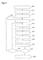
- Fig. 2 is a flowchart of the steps of processing the airbag cover 100 with ultrasonic waves using the ultrasonic processor 200.
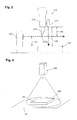
- Fig. 3 is a schematic view illustrating Steps S20 to S30 in Fig. 2.
- Fig. 4 is a schematic view illustrating Step S24 in Fig. 2.
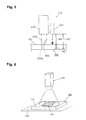
- Figs. 5 and 6 are schematic views illustrating Step S28 in Fig. 2.
- the processing process (ultrasonic processing process 201) in the embodiment is roughly divided into a data processing process of processing processing data before processing the airbag cover 100 and an actual processing process of actually processing the airbag cover 100 by the ultrasonic processor.
- processing data is obtained before actually processing the airbag cover 100.
- the data processing process comprises Steps S10 to S14 as shown in Fig. 2.
- Step S10 designing is performed by computer-aided design (CAD) based on design information of the airbag cover 100 in order to generate CAD data (processing data).
- CAD computer-aided design
- design information that is previously stored in a computer is output on a graphic display device to carry out the designing while watching the screen of the graphic display device.
- Step S12 the CAD data obtained in Step S10 is converted by computer-aided manufacturing (CAM) in order to generate CAM data.
- the CAM data is processing data (data for NC operation) at the NC control section 230.
- Step S14 the CAM data 231 (processing data) obtained in Step S12 is input to the NC control section 230 in order to carry out CAM data teaching.
- the CAM data that is input to the NC control section 230 once can be corrected at the NC control section 230 based on actual processing results.
- the actual processing process comprises Steps S20 to S30 as shown in, for example, Fig. 2.
- Step S20 prior to processing the airbag cover 100, a processing start position (origin) of the ultrasonic processing blade 216 is confirmed.
- the confirmation is carried out using, for example, the displacement meters 221 and 222 of laser types.
- the displacement meter 221 is disposed at a base, and the displacement meter 222 is disposed at the ultrasonic processing blade 216 of the drive section 210.
- the displacement meter 221 detects a height H1 (distance) from the top surface of a reference block 120 to the cutting blade 216a of the ultrasonic processing blade 216.
- the displacement meter 222 detects a height H2 (distance) from the top surface of the reference block 120 to the displacement meter 222. Then, by calculating the difference between the detected heights H1 and H2 (H2 - H1), a height H3 from the displacement meter 222 to the cutting edge 216a of the ultrasonic processing blade 216 is obtained (determined).
- the displacement meter 222 corresponds to the "predetermined location at the ultrasonic processing means" in the present invention. By this, the processing start position (origin) of the ultrasonic processing blade 216 is determined.
- the height H3 corresponds to the "first distance” in the present invention
- Step S20 corresponds to the "step of determining a first distance” in the present invention.
- the number of detection points for detecting the height H1 with the displacement meter 221 and that for detecting the height H2 by the displacement meter 222 in Step S20 may be set as required considering, for example, the shape of the airbag cover 100. For example, it is desirable that the more complicated the shape of the airbag cover 100 is, a larger number of detection points for detecting the heights H1 and H2 be used.
- Step S22 the airbag cover 100 is set on a receiver jig (receiver jig 130 in Fig. 4). Then, in Step S24, the set state of the airbag cover 100 is confirmed.
- the receiver jig 130 has an attracting mechanism using air.
- the attracting mechanism has a structure which allows detection of attraction pressure.
- the state of contact between the airbag cover 100 and the receiver jig 130 is confirmed by the attraction pressure of the attracting mechanism, and, as shown in Fig. 4, any shifts in the position of the airbag cover 100 is confirmed by the image testing camera 223.
- a worker can confirm the set state of the airbag cover 100.
- Step S26 the actual processing of the airbag cover 100 by the ultrasonic processing blade 216 is started.
- the ultrasonic wave oscillator 218 oscillates ultrasonic waves having a frequency of, for example, 22 kHz, and transmits them to the ultrasonic processing blade 216 through the ultrasonic oscillation portion 214.
- the drive arm 212 is controlled in order to adjust the position of the cutting edge 216a of the ultrasonic processing blade 216.
- the processing operation of the ultrasonic processing blade 216 is controlled so that it is carried in a predetermined path.
- the processing speed of the ultrasonic processing blade 216 may be, for example, 30 mm/sec. This processing speed is 1.5 times greater than a laser processing speed of 20 mm/sec, so that this method is effective in increasing the efficiency with which the airbag cover 100 is produced.
- Processing conditions such as the frequency of the ultrasonic waves oscillated from the ultrasonic oscillator 218 and the processing speed of the ultrasonic processing blade 216, can be set as required based on conditions of the object to be processed, such as the material or thickness of the airbag cover.
- Step S28 the state of processing by the ultrasonic processing blade 216 when the ultrasonic processing blade 216 is processing the airbag cover 100 in Step S26 is confirmed.
- the displacement meter 222 detects a height H4 (distance) from the back surface 101 of the airbag cover 100 to the displacement meter 222.
- the height H4 corresponds to the "second distance" in the present invention.
- a processing depth (cut depth) H5 of the tear line 102 can be obtained (determined). Accordingly, in the embodiment, the processing depth H5 of the tear line 102 is indirectly estimated based on other detection information, so that the processing depth H5 of the tear line 102 can be estimated without directly detecting it. Based on the processing depth H5 and control data of the NC control section 230, it is possible to confirm the residual thickness at the location of the tear line 102 of the airbag cover 100 ("residual thickness" in the present invention).
- the processing depth H5 corresponds to the "depth of the linear groove” in the present invention
- Step S28 corresponds to the "step of determining a second distance” in the present invention. In this way, the airbag cover 100 with the tear line 102 having a predetermined depth is produced.
- the number of detection points for detecting the height H4 by the displacement meter 222 may be set as required considering, for example, the shape of the airbag cover 100. For example, it is desirable that the more complicated the shape of the airbag cover 100 is, a larger number of detection points for detecting the height H4 be used. As shown in Fig. 6, the processing path of the tear line 102 is confirmed by the image testing camera 223.
- Step S30 the processing start position (origin) of the ultrasonic processing blade 216 is reconfirmed by carrying out the operations that are similar to those in Step S20.
- Step S32 a determination is made in Step S32 as to whether or not to process another airbag cover. If it is determined that another airbag cover is not to be processed in Step S32, the processing ends at 202. In contrast, if it is determined that another airbag cover is to be processed in Step S32, a determination is made in Step S34 as to whether or not processing data is to be corrected from the time of processing. If it is determined that the processing data is to be corrected in Step S34, the processing data is corrected in Step S36, after which the process returns to Step S14. In contrast, if it is determined that the processing data is not to be corrected in Step S34, the process returns to Step S20.
- the airbag cover 100 can be processed at a speed that is, for example, 1.5 times greater than the laser processing speed, so that this method is effective in increasing the efficiency with which the airbag cover 100 is produced.
- the tear line 102 which is a linear groove
- the ultrasonic processing blade 216 by using the ultrasonic processing blade 216, the tear line 102, which is a linear groove, can be continuously formed, so that the groove can have a uniform depth. Therefore, compared to the case in which grooves are formed in the form of dots by laser processing, the linear groove is effective in allowing smooth tearing of the airbag cover 100 when an airbag is deployed and inflated.
- the tear line 102 (having the depth H5 and a width d in the back surface 101) that is defined by sharp portions in cross section as shown in Figs. 7 and 8 can be formed.
- a tear line 103 comprising grooves that are discontinuously formed in the form of dots as shown in Fig. 9 is formed. Even if the distances between the dot-shaped grooves are decreased in the tear line 103 shown in Fig. 9, there is a limit as to how close the tearing ability at the tear line 103 can be compared to the tearing ability at the tear line 102 in the embodiment.
- the depth of the tear line 102 which is defined by the sharp portions in cross section in the embodiment may not be precisely measured. However, since, in the embodiment, the depth of the tear line 102 is indirectly measured, the tear line 102 can be defined by the sharp portions in cross section.
- the tear line 102 defined by the sharp portions in cross section is effective in maintaining a good tearing ability during the deployment and inflation of the airbag.
- the embodiment is particularly effective in reliably forming the tear line 102 with a predetermined depth in the three-dimensionally molded airbag cover.
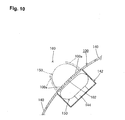
- the airbag cover 100 produced by the above-described method may be incorporated in a vehicle, for example, as shown in Fig. 10.
- parts such as the airbag cover 100, an instrument panel 140 at which the airbag cover 100 is disposed, a vehicle airbag 150, an accommodating member (retainer) 142 in which the vehicle airbag 150 is accommodated in a folded state, and gas supplying means (inflator) 144, disposed in the accommodating member 142, for supplying inflation gas to the vehicle airbag 150 may form an airbag module.
- This airbag module corresponds to the "airbag module" in the present invention.
- the gas supplying means 144 When a vehicle collides at a location which is situated in front of the vehicle, the gas supplying means 144 operates to deploy the vehicle airbag 150 by inflation gas supplied from the gas supplying means 144.
- the airbag cover 100 is torn at the tear line 102 during the deployment and inflation of the vehicle airbag 150, so that, for example, a pair of deployment doors 100a are both opened towards the front surface of the airbag cover 100.
- the vehicle airbag 150 is deployed outward from the airbag cover 100 through the deployment doors 100a that are opened, so that it is further deployed and inflated while protruding towards a rider protection area 160 that is situated in front of a rider.
- the present invention provides an efficient technology of constructing an airbag cover for covering a vehicle airbag, and related technologies thereof.
Landscapes
- Engineering & Computer Science (AREA)
- Mechanical Engineering (AREA)
- Air Bags (AREA)
- Instrument Panels (AREA)
- Machine Tool Sensing Apparatuses (AREA)
Abstract
Description
- The present invention relates to a technology of constructing an airbag cover for covering a vehicle airbag.
- An airbag device which is mounted to a vehicle has an airbag cover for covering an airbag. The airbag cover has a tear line (linear groove) in an inner wall surface thereof, and allows deployment and inflation of the airbag outward from the airbag cover as a result of tearing at the tear line when the vehicle collides. As a technology in which a tear line is formed in an airbag cover by post-processing, a technology using, for example, laser cutting is known (refer to, for example, PCT Japanese Translation Patent Publication No. 2001-502996).
- However, in such a technology of forming a tear line using laser cutting, there is a limit as to how much processing costs are reduced due to the use of a laser processing structure. To overcome this problem, the present inventor et al. devoted themselves to studying efficient technologies of forming a tear line in order to reduce costs of producing an airbag cover with a tear line that is formed by post-processing. The present inventor et al. conducted such studies considering that there is a great demand for a technology of forming a linear groove in an airbag cover whose shape is becoming complicated due to setting the airbag cover at various locations in recent years. As a result of the studies, the present inventor et al. were successful in finding out that a tear line can be formed even in an airbag cover with a complicated shape at a low cost by post-processing.
- An object of the present invention is to provide an efficient technology of constructing an airbag cover for covering a vehicle airbag, and related technologies thereof.
- According to the invention this object is achieved by a method of producing an airbag cover as defined in claim 1, an airbag cover as defined in claim 3 or an airbag module as defined in claim 4. The dependent claim defines a preferred and advantageous embodiment of the invention.
- To this end, the inventions of the claims are provided, and are related to technologies applicable to various vehicles including automobiles, trains, motorcycles (vehicles that a rider sits astride), airplanes, and ships.
- The invention relates to a method of producing an airbag cover for covering a vehicle airbag that is mounted to various vehicles. In the method, a three-dimensionally molded plate-shaped airbag cover is post-processed by ultrasonic processing means in order to form a linear groove in the airbag cover. In other words, in the present invention, using the ultrasonic processing means, a linear groove is formed in a molded airbag cover. The linear groove is a groove which is continuously formed with a predetermined depth within the thickness of the plate-shaped airbag cover. The linear groove is defined by a relatively thin portion of the airbag cover, and is what is called a tear line. The airbag cover is torn at the linear groove when the airbag is deployed and inflated.
- In the specification, the term "ultrasonic processing means" is mainly used to widely include various structures which can process an object by transmitting (imparting) ultrasonic waves to the object. A typical example is a structure for processing an object with ultrasonic waves by operating a blade-like member (ultrasonic processing blade) upon the object. Examples of ultrasonic processing means other than a blade-like member include rod-shaped or plate-shaped ultrasonic processing means. A typical example of a processor using the ultrasonic processing means is a structure for controlling the operation of the ultrasonic processing blade to which ultrasonic waves are transmitted by a processing robot. By this, the operation of the ultrasonic processing blade is controlled so that it is carried out in a predetermined path.
- According to the present invention, by using the ultrasonic processing means, it is possible to provide an efficient method of producing an airbag cover having a linear groove formed by post-processing. In other words, the processing speed when, for example, an ultrasonic processing blade is used as ultrasonic processing means is greater than the processing speed when laser is used (for example, approximately 1.5 times greater), so that the technology using the ultrasonic processing means is effective in increasing the efficiency with which the airbag cover is produced. In addition, it is possible to use a general-purpose machine in a facility of, for example, the ultrasonic processing means and a processing robot. Therefore, compared to a laser processing facility having a greater need for using a special-purpose machine, facility costs can be reduced.
- As in the present invention, the technology of post-processing a three-dimensionally molded plate-shaped airbag cover using ultrasonic processing means makes it possible to meet the demands arising when the shapes of the airbag cover become complicated because it is set at various locations. As opposed to such a technology of the present invention, there is, for example, another technology in which a linear groove is two-dimensionally formed in an outer portion of the airbag cover in a plane by the ultrasonic processing means, and, then, this outer portion is disposed at a three-dimensionally molded location, so that the airbag cover has a three-dimensional form as a whole. However, when such a technology is used, there is a limit as to how much production costs are reduced because the process of producing the airbag cover becomes complicated. Accordingly, a technology, such as that of the present invention, of directly processing a three-dimensionally molded plate-shaped airbag cover by the ultrasonic processing means is effective in simplifying the production process. Therefore, according to the present invention, it is possible to reduce the production time as a result of simplifying the production process itself, in addition to reducing the production time by using the ultrasonic processing means having a high processing speed.
- According to the present invention, by using the ultrasonic processing means, it is possible to provide a technology of processing a highly reliable linear groove which makes it possible for the airbag cover to tear when the airbag is deployed and inflated. In other words, when laser is used, due to structural reasons, grooves are formed discontinuously in the form of dots. Therefore, the depths of the grooves may be ununiform. However, when the ultrasonic processing means is used as in the present invention, a linear groove is continuously formed. In particular, by controlling the operation of the ultrasonic processing means by, for example, a processing robot, the depth of the groove can be uniform. A linear groove having uniform depth as in the present invention is effective in smoothly tearing the airbag cover when the airbag is deployed and inflated.
- In the invention, before forming the linear groove, a first distance between a processing edge of the ultrasonic processing means, such as a cutting edge of an ultrasonic processing blade, and a predetermined location at the ultrasonic processing means can be determined. In addition, when the linear groove is to be formed, a second distance between a processing surface of the airbag cover and a predetermined location at the ultrasonic processing means can be determined. The first and second distances can be determined using, for example, information detected by a laser displacement meter. In the specification, the term "determine" is used to widely include a mode of directly obtaining predetermined data using a detector and a mode of obtaining predetermined data by further processing the data detected by the detector by, for example, computation. By the difference between the determined first and second distances, the distance that the ultrasonic processing means has penetrated from the processing surface of the airbag cover in a plate thickness direction during processing, that is, the depth of the linear groove or the residual thickness at the linear groove can be determined. Typically, after determining the depth of the linear groove, the residual thickness at the linear groove is determined from the depth of the linear groove.
- According to the present invention, it is possible to indirectly estimate the depth of the linear groove from the first and second distances, so that it can be estimated without directly measuring the depth of the linear groove. When the depth of the linear groove is to be directly measured, it is difficult to precisely measure the depth of the linear groove unless the width of the linear groove (length of the linear groove in a direction perpendicular to the direction of extension of the linear groove) is a certain value. However, if the width of the linear groove is increased, the airbag cover may be less properly torn at the linear groove. To overcome this problem, the depth of the linear groove can be indirectly measured from the first and second distances as in the present invention, thereby making it possible to maintain a good tearing ability at the linear groove of the airbag cover.
- According to a first aspect of the invention the airbag cover has a three-dimensionally molded plate-shaped structure, and has a linear groove which is continuously formed with a predetermined depth within the thickness of the airbag cover. The linear groove is formed by post-processing. Typically, the linear groove is formed by ultrasonic processing means as described before.
- The linear groove in the present invention has a uniform depth compared to, for example, grooves formed discontinuously in the form of dots by laser processing, so that the linear groove is effective in allowing smooth tearing of the airbag cover when a vehicle airbag is deployed and inflated.
- According to a second aspect of the invention the invention relates to a structure of an airbag module. The airbag module comprises, for example, a vehicle airbag, an accommodating member for accommodating the vehicle airbag, gas supplying means for supplying inflation gas to the vehicle airbag, and an airbag cover which is substantially the same as that described according to the first aspect of the invention. The whole airbag module is mounted to a vehicle. The airbag module of the present invention may also include a member to which the airbag cover is disposed, that is, what is called an instrument panel.
- According to the second aspect of the invention, it is possible to provide an efficient technology of constructing an airbag module which is effective in allowing smooth tearing of the airbag cover when the vehicle airbag is deployed and inflated.
-
- Fig. 1 shows the structures of an
airbag cover 100 and anultrasonic processor 200 of the embodiments, with theultrasonic processor 200 processing theairbag cover 100. - Fig. 2 is a flowchart of the steps of processing the
airbag cover 100 with ultrasonic waves by theultrasonic processor 200. - Fig. 3 is a schematic view illustrating Steps S20 to S30 in Fig. 2.
- Fig. 4 is a schematic view illustrating Step S24 in Fig. 2.
- Fig. 5 is a schematic view illustrating Step S28 in Fig. 2.
- Fig. 6 is a schematic view illustrating Step S28 in Fig. 2.
- Fig. 7 is a sectional view of a form of a
tear line 102 formed in theairbag cover 100 by carrying out the ultrasonic processing process illustrated in Fig. 2. - Fig. 8 is a sectional view taken in a direction of
extension of the
tear line 102 shown in Fig. 7. - Fig. 9 is a sectional view of a form of a
tear line 103 formed by laser processing. - Fig. 10 is a sectional view of the structure of an
airbag module, with the
airbag cover 100 being torn. -
- Hereunder, a description of embodiments of the present invention will be given with reference to the drawings. The embodiment is that of a technology of forming a
tear line 102 by ultrasonic processing in aback surface 101 of anairbag cover 100 for covering a vehicle airbag. - First, the structures of the
airbag cover 100 and anultrasonic processor 200 will be described with reference to Fig. 1. Fig. 1 shows the structures of theairbag cover 100 and theultrasonic processor 200 of the embodiments, with theultrasonic processor 200 processing theairbag cover 100. - The
airbag cover 100 shown in Fig. 1 is a plate-shaped cover which has been three-dimensionally molded out of resin material such as a polypropylene (PP) material or an olefin elastomer (TPO) material. Theback surface 101 of theairbag cover 100 is defined as such when the surface of theairbag cover 100 that opposes a rider is defined as the front surface. Thetear line 102 is defined by a thin portion of theairbag cover 100 in order to allow tearing of theairbag cover 100 when the airbag is deployed and inflated, and is, in the embodiment, a linear groove formed in theback surface 101 of theairbag cover 100. Thetear line 102 corresponds to the "linear groove which is continuously formed with a predetermined depth within the thickness of the airbag cover" in the present invention. - As shown in Fig. 1, the
ultrasonic processor 200 roughly comprises adrive section 210 and anNC control section 230. Thedrive section 210 comprises, for example, adrive arm 212, anultrasonic oscillation portion 214, anultrasonic processing blade 216, and anultrasonic wave oscillator 218. - The
drive arm 212 forms a portion of a processing robot, and is controlled based on an input signal from theNC control section 230 in order to adjust the position of acutting edge 216a of theultrasonic processing blade 216. Theultrasonic oscillation portion 214 transmits ultrasonic waves oscillated by theultrasonic wave oscillator 218 to theultrasonic processing blade 216. Thecutting edge 216a of theultrasonic processing blade 216 may have a width of, for example, 1 mm. Theultrasonic processing blade 216 corresponds to the "ultrasonic processing means" in the present invention, and thecutting edge 216a of theultrasonic processing blade 216 corresponds to the "processing edge" in the present invention. As long as a member can process an object by transmitting (imparting) ultrasonic waves to the object, for example, a rod-shaped or a plate-shaped member may be used in addition to a blade-like member such as theultrasonic processing blade 216 in the embodiment. As theultrasonic wave oscillator 218, an ultrasonic wave oscillator which can oscillate ultrasonic waves having a frequency of, for example, 22 kHz is used. Theultrasonic processor 200 in the embodiment also comprisesdisplacement meters image testing camera 223, which are described later. - The
NC control section 230 is used for processing processing data for forming thetear line 102 in theback surface 101 of theairbag cover 100. Although not particularly illustrated, theNC control section 230, for example, inputs, computes, and outputs data for processing theairbag cover 100. - Next, the steps of forming the
tear line 102 by post-processing the moldedairbag cover 100 using theultrasonic processor 200 having the above-described structure will be described with reference to Figs. 2 to 6. Fig. 2 is a flowchart of the steps of processing theairbag cover 100 with ultrasonic waves using theultrasonic processor 200. Fig. 3 is a schematic view illustrating Steps S20 to S30 in Fig. 2. Fig. 4 is a schematic view illustrating Step S24 in Fig. 2. Figs. 5 and 6 are schematic views illustrating Step S28 in Fig. 2. - The processing process (ultrasonic processing process 201) in the embodiment is roughly divided into a data processing process of processing processing data before processing the
airbag cover 100 and an actual processing process of actually processing theairbag cover 100 by the ultrasonic processor. - In the data processing process, processing data is obtained before actually processing the
airbag cover 100. The data processing process comprises Steps S10 to S14 as shown in Fig. 2. - First, in Step S10, designing is performed by computer-aided design (CAD) based on design information of the
airbag cover 100 in order to generate CAD data (processing data). Here, for example, design information that is previously stored in a computer is output on a graphic display device to carry out the designing while watching the screen of the graphic display device. - In Step S12, the CAD data obtained in Step S10 is converted by computer-aided manufacturing (CAM) in order to generate CAM data. The CAM data is processing data (data for NC operation) at the
NC control section 230. - In Step S14, the CAM data 231 (processing data) obtained in Step S12 is input to the
NC control section 230 in order to carry out CAM data teaching. In the embodiment, the CAM data that is input to theNC control section 230 once can be corrected at theNC control section 230 based on actual processing results. - When the data processing process is completed, the
airbag cover 100 is actually processed. The actual processing process comprises Steps S20 to S30 as shown in, for example, Fig. 2. - First, in Step S20, prior to processing the
airbag cover 100, a processing start position (origin) of theultrasonic processing blade 216 is confirmed. The confirmation is carried out using, for example, thedisplacement meters displacement meter 221 is disposed at a base, and thedisplacement meter 222 is disposed at theultrasonic processing blade 216 of thedrive section 210. In such a structure, as shown in Fig. 3, thedisplacement meter 221 detects a height H1 (distance) from the top surface of areference block 120 to thecutting blade 216a of theultrasonic processing blade 216. Thedisplacement meter 222 detects a height H2 (distance) from the top surface of thereference block 120 to thedisplacement meter 222. Then, by calculating the difference between the detected heights H1 and H2 (H2 - H1), a height H3 from thedisplacement meter 222 to thecutting edge 216a of theultrasonic processing blade 216 is obtained (determined). Thedisplacement meter 222 corresponds to the "predetermined location at the ultrasonic processing means" in the present invention. By this, the processing start position (origin) of theultrasonic processing blade 216 is determined. The height H3 corresponds to the "first distance" in the present invention, and Step S20 corresponds to the "step of determining a first distance" in the present invention. - The number of detection points for detecting the height H1 with the
displacement meter 221 and that for detecting the height H2 by thedisplacement meter 222 in Step S20 may be set as required considering, for example, the shape of theairbag cover 100. For example, it is desirable that the more complicated the shape of theairbag cover 100 is, a larger number of detection points for detecting the heights H1 and H2 be used. - Next, in Step S22, the
airbag cover 100 is set on a receiver jig (receiver jig 130 in Fig. 4). Then, in Step S24, the set state of theairbag cover 100 is confirmed. - Although not particularly illustrated, the
receiver jig 130 has an attracting mechanism using air. By operating the attracting mechanism, theairbag cover 100 can be attracted to and held by thereceiver jig 130. The attracting mechanism has a structure which allows detection of attraction pressure. In such a structure, the state of contact between theairbag cover 100 and thereceiver jig 130 is confirmed by the attraction pressure of the attracting mechanism, and, as shown in Fig. 4, any shifts in the position of theairbag cover 100 is confirmed by theimage testing camera 223. By this, a worker can confirm the set state of theairbag cover 100. - In Step S26, the actual processing of the
airbag cover 100 by theultrasonic processing blade 216 is started. Here, theultrasonic wave oscillator 218 oscillates ultrasonic waves having a frequency of, for example, 22 kHz, and transmits them to theultrasonic processing blade 216 through theultrasonic oscillation portion 214. Based on an input signal from theNC control section 230, thedrive arm 212 is controlled in order to adjust the position of thecutting edge 216a of theultrasonic processing blade 216. By this, the processing operation of theultrasonic processing blade 216 is controlled so that it is carried in a predetermined path. The processing speed of theultrasonic processing blade 216 may be, for example, 30 mm/sec. This processing speed is 1.5 times greater than a laser processing speed of 20 mm/sec, so that this method is effective in increasing the efficiency with which theairbag cover 100 is produced. - Processing conditions, such as the frequency of the ultrasonic waves oscillated from the
ultrasonic oscillator 218 and the processing speed of theultrasonic processing blade 216, can be set as required based on conditions of the object to be processed, such as the material or thickness of the airbag cover. - In Step S28, the state of processing by the
ultrasonic processing blade 216 when theultrasonic processing blade 216 is processing theairbag cover 100 in Step S26 is confirmed. Here, as shown in Fig. 5, thedisplacement meter 222 detects a height H4 (distance) from theback surface 101 of theairbag cover 100 to thedisplacement meter 222. The height H4 corresponds to the "second distance" in the present invention. - By calculating the difference (H3 - H4) between the height H3 (from the
displacement meter 222 to thecutting edge 216a of the ultrasonic processing blade 216) previously detected in Step S20 and the height H4, a processing depth (cut depth) H5 of thetear line 102 can be obtained (determined). Accordingly, in the embodiment, the processing depth H5 of thetear line 102 is indirectly estimated based on other detection information, so that the processing depth H5 of thetear line 102 can be estimated without directly detecting it. Based on the processing depth H5 and control data of theNC control section 230, it is possible to confirm the residual thickness at the location of thetear line 102 of the airbag cover 100 ("residual thickness" in the present invention). The processing depth H5 corresponds to the "depth of the linear groove" in the present invention, and Step S28 corresponds to the "step of determining a second distance" in the present invention. In this way, theairbag cover 100 with thetear line 102 having a predetermined depth is produced. - In Step S28, the number of detection points for detecting the height H4 by the
displacement meter 222 may be set as required considering, for example, the shape of theairbag cover 100. For example, it is desirable that the more complicated the shape of theairbag cover 100 is, a larger number of detection points for detecting the height H4 be used. As shown in Fig. 6, the processing path of thetear line 102 is confirmed by theimage testing camera 223. - In Step S30, the processing start position (origin) of the
ultrasonic processing blade 216 is reconfirmed by carrying out the operations that are similar to those in Step S20. - After Step S30 is completed, a determination is made in Step S32 as to whether or not to process another airbag cover. If it is determined that another airbag cover is not to be processed in Step S32, the processing ends at 202. In contrast, if it is determined that another airbag cover is to be processed in Step S32, a determination is made in Step S34 as to whether or not processing data is to be corrected from the time of processing. If it is determined that the processing data is to be corrected in Step S34, the processing data is corrected in Step S36, after which the process returns to Step S14. In contrast, if it is determined that the processing data is not to be corrected in Step S34, the process returns to Step S20.
- As described above, in the embodiment, since the
ultrasonic processing blade 216 is used, theairbag cover 100 can be processed at a speed that is, for example, 1.5 times greater than the laser processing speed, so that this method is effective in increasing the efficiency with which theairbag cover 100 is produced. In addition, it is possible to use a general-purpose machine in a facility of, for example, theultrasonic processing blade 216 and a processing robot. Therefore, compared to a laser processing facility having a greater need for a special-purpose machine, facility costs can be reduced. - As opposed to the embodiment, there is, for example, another technology in which a linear groove is two-dimensionally formed in an outer portion of an airbag cover in a plane by an ultrasonic processing blade, and, then, this outer portion is disposed at a three-dimensionally molded location, so that the airbag cover has a three-dimensional form as a whole. However, when such a technology is used, there is a limit as to how much production costs are reduced because the process of producing the airbag cover becomes complicated. Accordingly, a technology, such as that of the present invention, of directly processing a three-dimensionally molded plate-shaped airbag cover by the ultrasonic processing blade is effective in simplifying the production process. Therefore, according to the present invention, it is possible to reduce the production time as a result of simplifying the production process itself, in addition to reducing the production time by using the ultrasonic processing blade having a high processing speed.
- According to the embodiment, by using the
ultrasonic processing blade 216, thetear line 102, which is a linear groove, can be continuously formed, so that the groove can have a uniform depth. Therefore, compared to the case in which grooves are formed in the form of dots by laser processing, the linear groove is effective in allowing smooth tearing of theairbag cover 100 when an airbag is deployed and inflated. In other words, in the embodiment, by processing theairbag cover 100 by theultrasonic processing blade 216 in Step S26, for example, the tear line 102 (having the depth H5 and a width d in the back surface 101) that is defined by sharp portions in cross section as shown in Figs. 7 and 8 can be formed. In contrast, when laser processing is carried out, for example, atear line 103 comprising grooves that are discontinuously formed in the form of dots as shown in Fig. 9 is formed. Even if the distances between the dot-shaped grooves are decreased in thetear line 103 shown in Fig. 9, there is a limit as to how close the tearing ability at thetear line 103 can be compared to the tearing ability at thetear line 102 in the embodiment. - When the depth of the
tear line 102 is to be directly measured, the depth of thetear line 102 which is defined by the sharp portions in cross section in the embodiment may not be precisely measured. However, since, in the embodiment, the depth of thetear line 102 is indirectly measured, thetear line 102 can be defined by the sharp portions in cross section. Thetear line 102 defined by the sharp portions in cross section is effective in maintaining a good tearing ability during the deployment and inflation of the airbag. - When the three-dimensional form of the airbag cover, which is an object to be processed, is complicated, it is sometimes difficult to directly detect the processing depth H5 of the
tear line 102. Since, in the embodiment, information regarding the processing depth H5 of thetear line 102 is constantly detected during the processing to determine a highly reliably processing depth H5, the embodiment is particularly effective in reliably forming thetear line 102 with a predetermined depth in the three-dimensionally molded airbag cover. - The
airbag cover 100 produced by the above-described method may be incorporated in a vehicle, for example, as shown in Fig. 10. In other words, parts such as theairbag cover 100, aninstrument panel 140 at which theairbag cover 100 is disposed, avehicle airbag 150, an accommodating member (retainer) 142 in which thevehicle airbag 150 is accommodated in a folded state, and gas supplying means (inflator) 144, disposed in theaccommodating member 142, for supplying inflation gas to thevehicle airbag 150 may form an airbag module. This airbag module corresponds to the "airbag module" in the present invention. - When a vehicle collides at a location which is situated in front of the vehicle, the gas supplying means 144 operates to deploy the
vehicle airbag 150 by inflation gas supplied from thegas supplying means 144. Theairbag cover 100 is torn at thetear line 102 during the deployment and inflation of thevehicle airbag 150, so that, for example, a pair ofdeployment doors 100a are both opened towards the front surface of theairbag cover 100. In this way, thevehicle airbag 150 is deployed outward from theairbag cover 100 through thedeployment doors 100a that are opened, so that it is further deployed and inflated while protruding towards arider protection area 160 that is situated in front of a rider. - The present invention provides an efficient technology of constructing an airbag cover for covering a vehicle airbag, and related technologies thereof.
Claims (4)
- A method of producing an airbag cover for covering a vehicle airbag, the method comprising the step of:post-processing a three-dimensionally molded plate-shaped airbag cover (100) by ultrasonic processing means (216) such that a linear groove (102) with a predetermined depth within the thickness of the airbag cover (100) is continuously formed on the airbag cover (100).
- A method of producing an airbag cover according to Claim 1, further comprising the step (S20) of determining a first distance (H3) between a processing edge (216a) of the ultrasonic processing means (216) and a predetermined location (222) at the ultrasonic processing means (216) before forming the linear groove (102) and the step (S28) of determining a second distance (H4) between a processing surface (101) of the airbag cover (100) and the predetermined location (222) at the ultrasonic processing means (216) during the formation of the linear groove (102) in order to estimate a depth (H5) of the linear groove (102) or a residual thickness at the linear groove (102) based on the determined first (H3) and second (H4) distances.
- A three-dimensionally molded plate-shaped airbag cover for covering a vehicle airbag, the airbag cover (100) comprising:a linear groove (102) disposed continuously with a predetermined depth within the thickness of the airbag cover (100) by post-processing.
- An airbag module comprising:wherein the airbag cover (100) has a three-dimensionally molded plate-shaped structure and has a linear groove (102) which is continuously disposed with a predetermined depth within the thickness of the airbag cover (100) by post-processing, anda vehicle airbag (150);an airbag cover (100) for covering the vehicle airbag (150);an accommodating member (142) for accommodating the vehicle airbag (150); andgas supplying means (144) for supplying inflation gas so that the vehicle airbag (150) is deployed and inflated from the accommodating member (142),
wherein, when a vehicle collides at a location which is situated in front of the vehicle, the vehicle airbag (150) is deployed by the inflation gas supplied from the gas supplying means (144), causing the airbag cover (100) to tear at the linear groove (102), so that the vehicle airbag (150) is further deployed and inflated in a rider protection area which is situated in front of a rider.
Applications Claiming Priority (2)
| Application Number | Priority Date | Filing Date | Title |
|---|---|---|---|
| JP2003187626 | 2003-06-30 | ||
| JP2003187626A JP4227851B2 (en) | 2003-06-30 | 2003-06-30 | Manufacturing method of airbag cover |
Publications (2)
| Publication Number | Publication Date |
|---|---|
| EP1493548A1 true EP1493548A1 (en) | 2005-01-05 |
| EP1493548B1 EP1493548B1 (en) | 2006-11-29 |
Family
ID=33432263
Family Applications (1)
| Application Number | Title | Priority Date | Filing Date |
|---|---|---|---|
| EP04012417A Expired - Lifetime EP1493548B1 (en) | 2003-06-30 | 2004-05-26 | Airbag cover, airbag module, and method of producing the airbag cover |
Country Status (5)
| Country | Link |
|---|---|
| US (1) | US20040262892A1 (en) |
| EP (1) | EP1493548B1 (en) |
| JP (1) | JP4227851B2 (en) |
| CN (1) | CN1576112A (en) |
| DE (1) | DE602004003428T2 (en) |
Cited By (3)
| Publication number | Priority date | Publication date | Assignee | Title |
|---|---|---|---|---|
| EP1566314A1 (en) * | 2004-02-19 | 2005-08-24 | Takata Corporation | Method of manufacturing an airbag cover and corresponding ultrasonic processing device |
| EP1623883A1 (en) * | 2004-08-05 | 2006-02-08 | Eissmann Automotive Deutschland GmbH | Cover for an airbag housing |
| US7497463B2 (en) | 2004-08-05 | 2009-03-03 | Eissmann Automotive Deutschland Gmbh | Lining for the cover of an airbag |
Families Citing this family (10)
| Publication number | Priority date | Publication date | Assignee | Title |
|---|---|---|---|---|
| DE102005008095A1 (en) * | 2005-02-22 | 2006-08-31 | Geiss Ag | Device and method for introducing lines of weakness into a rigid component |
| JP4582006B2 (en) * | 2006-01-16 | 2010-11-17 | 豊田合成株式会社 | Manufacturing method of airbag cover |
| JP4582005B2 (en) * | 2006-01-16 | 2010-11-17 | 豊田合成株式会社 | Manufacturing method of airbag cover |
| JP4726656B2 (en) * | 2006-03-10 | 2011-07-20 | 株式会社仲田コーティング | Apparatus for manufacturing vehicle interior member having airbag door and method for manufacturing vehicle interior member having airbag door |
| FR2916175B1 (en) * | 2007-05-16 | 2009-11-27 | Faurecia Interieur Ind | CLOTHING ELEMENT OF THE INTERIOR OF A MOTOR VEHICLE. |
| JP4834607B2 (en) * | 2007-05-18 | 2011-12-14 | 株式会社仲田コーティング | Airbag fracture groove forming apparatus and interior member manufacturing method |
| JP5170664B2 (en) * | 2008-05-22 | 2013-03-27 | スターテクノ株式会社 | Panel thickness measurement method for airbag tear line |
| US8567815B2 (en) * | 2011-09-08 | 2013-10-29 | Faurecia Interior Systems, Inc. | Limiting energy leakage during laser scoring of vehicle airbag coverings |
| US9527468B2 (en) * | 2014-02-04 | 2016-12-27 | Zodiac Seats France | Airbag door assembly |
| US10604259B2 (en) | 2016-01-20 | 2020-03-31 | Amsafe, Inc. | Occupant restraint systems having extending restraints, and associated systems and methods |
Citations (6)
| Publication number | Priority date | Publication date | Assignee | Title |
|---|---|---|---|---|
| US5968381A (en) * | 1995-12-13 | 1999-10-19 | Trw Occupant Restraint Systems Gmbh | Method for the manufacture of a gas bag cover using laser scoring |
| DE10042264A1 (en) * | 2000-06-30 | 2002-01-10 | Huber & Grimme Bearbeitungssys | Routing cutter, for scoring soft materials, e.g. dashboard cover for airbag in vehicles, has a cutting tip shaped as half cone |
| EP1177878A1 (en) * | 1999-11-17 | 2002-02-06 | Pearl Kogyo Co., Ltd | Method and device for forming linear groove in car skin air bag |
| EP1193140A2 (en) * | 2000-09-29 | 2002-04-03 | Toyoda Gosei Co., Ltd. | Air bag cover |
| US20020043144A1 (en) * | 1999-03-01 | 2002-04-18 | Stefan Reh | Method and device for forming a tear line in an airbag cover, and the cover thereof |
| EP1362687A1 (en) * | 1998-06-25 | 2003-11-19 | Tip Engineering Group, Inc. | Process for manufacturing an automotive trim piece preweakened to form an air bag deployment opening |
Family Cites Families (18)
| Publication number | Priority date | Publication date | Assignee | Title |
|---|---|---|---|---|
| US3019690A (en) * | 1956-03-10 | 1962-02-06 | Continental Elektro Ind Ag | Instrument for measuring distances and the like |
| US5744776A (en) * | 1989-07-14 | 1998-04-28 | Tip Engineering Group, Inc. | Apparatus and for laser preweakening an automotive trim cover for an air bag deployment opening |
| JP3201243B2 (en) * | 1995-12-12 | 2001-08-20 | 豊田合成株式会社 | Automotive interior parts with lid for airbag |
| JPH09156445A (en) * | 1995-12-12 | 1997-06-17 | Toyoda Gosei Co Ltd | Air bag cover |
| GB9714114D0 (en) * | 1997-07-03 | 1997-09-10 | Sanko Gosei Uk Ltd | Air bag |
| US6453535B1 (en) * | 1998-06-25 | 2002-09-24 | Tip Engineering Group, Inc. | Process for manufacturing an automotive trim piece preweakened to form an air bag deployment opening |
| DE19855803B4 (en) * | 1998-12-03 | 2006-01-26 | Gfm Gmbh | Method and device for producing a chamfer or a keyway on a workpiece |
| EP1067361A1 (en) * | 1999-07-06 | 2001-01-10 | Datalogic S.P.A. | Method and a device for measuring the distance of an object |
| US6402189B1 (en) * | 2000-02-15 | 2002-06-11 | Textron Automotive Company, Inc | Airbag door and method for making same |
| US6709007B2 (en) * | 2000-02-15 | 2004-03-23 | Collins & Aikman Automotive Company Inc. | Airbag door and method for making same |
| US6892616B2 (en) * | 2000-11-28 | 2005-05-17 | Uht Corporation | Cutting apparatus |
| US6692019B2 (en) * | 2001-03-13 | 2004-02-17 | Delphi Technologies, Inc. | Method to create invisible air bag deployment panel |
| US6737607B2 (en) * | 2001-03-16 | 2004-05-18 | Tip Engineering Group, Inc. | Apparatus for laser cutting a workpiece |
| US20030025305A1 (en) * | 2001-07-31 | 2003-02-06 | Speelman Phillip Brian | Air bag cover assembly |
| US7128334B2 (en) * | 2002-09-17 | 2006-10-31 | Collins & Aikman Products Co. | Ultrasonic blade design for scoring double angle groove and products therefrom |
| ATE334853T1 (en) * | 2003-01-15 | 2006-08-15 | Frimo Group Gmbh | CUTTING TOOL FOR IN-PROCESS CONTROL OF THE RESIDUAL WALL THICKNESS DURING AIR BAG WEAKENING AND METHOD THEREOF |
| JP2006036148A (en) * | 2004-07-29 | 2006-02-09 | Takata Corp | Airbag cover manufacturing device |
| US20060119136A1 (en) * | 2004-12-03 | 2006-06-08 | Lear Corporation | Method of manufacturing a scored vehicular panel and article made thereby |
-
2003
- 2003-06-30 JP JP2003187626A patent/JP4227851B2/en not_active Expired - Fee Related
-
2004
- 2004-04-15 US US10/824,373 patent/US20040262892A1/en not_active Abandoned
- 2004-04-16 CN CNA2004100368518A patent/CN1576112A/en active Pending
- 2004-05-26 EP EP04012417A patent/EP1493548B1/en not_active Expired - Lifetime
- 2004-05-26 DE DE602004003428T patent/DE602004003428T2/en not_active Expired - Lifetime
Patent Citations (6)
| Publication number | Priority date | Publication date | Assignee | Title |
|---|---|---|---|---|
| US5968381A (en) * | 1995-12-13 | 1999-10-19 | Trw Occupant Restraint Systems Gmbh | Method for the manufacture of a gas bag cover using laser scoring |
| EP1362687A1 (en) * | 1998-06-25 | 2003-11-19 | Tip Engineering Group, Inc. | Process for manufacturing an automotive trim piece preweakened to form an air bag deployment opening |
| US20020043144A1 (en) * | 1999-03-01 | 2002-04-18 | Stefan Reh | Method and device for forming a tear line in an airbag cover, and the cover thereof |
| EP1177878A1 (en) * | 1999-11-17 | 2002-02-06 | Pearl Kogyo Co., Ltd | Method and device for forming linear groove in car skin air bag |
| DE10042264A1 (en) * | 2000-06-30 | 2002-01-10 | Huber & Grimme Bearbeitungssys | Routing cutter, for scoring soft materials, e.g. dashboard cover for airbag in vehicles, has a cutting tip shaped as half cone |
| EP1193140A2 (en) * | 2000-09-29 | 2002-04-03 | Toyoda Gosei Co., Ltd. | Air bag cover |
Cited By (3)
| Publication number | Priority date | Publication date | Assignee | Title |
|---|---|---|---|---|
| EP1566314A1 (en) * | 2004-02-19 | 2005-08-24 | Takata Corporation | Method of manufacturing an airbag cover and corresponding ultrasonic processing device |
| EP1623883A1 (en) * | 2004-08-05 | 2006-02-08 | Eissmann Automotive Deutschland GmbH | Cover for an airbag housing |
| US7497463B2 (en) | 2004-08-05 | 2009-03-03 | Eissmann Automotive Deutschland Gmbh | Lining for the cover of an airbag |
Also Published As
| Publication number | Publication date |
|---|---|
| JP4227851B2 (en) | 2009-02-18 |
| US20040262892A1 (en) | 2004-12-30 |
| JP2005022452A (en) | 2005-01-27 |
| EP1493548B1 (en) | 2006-11-29 |
| DE602004003428T2 (en) | 2007-09-27 |
| DE602004003428D1 (en) | 2007-01-11 |
| CN1576112A (en) | 2005-02-09 |
Similar Documents
| Publication | Publication Date | Title |
|---|---|---|
| EP1493548B1 (en) | Airbag cover, airbag module, and method of producing the airbag cover | |
| US7284975B2 (en) | Manufacturing apparatus for airbag cover | |
| JP4659382B2 (en) | Manufacturing method of airbag cover | |
| US5883356A (en) | Laser scoring process and apparatus | |
| CN100457513C (en) | Airbagabdeckung | |
| US20010037998A1 (en) | Process and apparatus for weakening an automotive trim piece for an airbag deployment opening | |
| EP1918162B1 (en) | Airbag cover, instrument panel, and airbag apparatus | |
| AU2001247477A1 (en) | Process and apparatus for weakening an automotive trim piece for an airbag deployment opening | |
| US20080157511A1 (en) | Airbag module | |
| AU2005200287A1 (en) | Airbag Apparatus for Automobile | |
| JP4439940B2 (en) | Manufacturing method of airbag cover | |
| JP2003212075A (en) | Tear-line structure of airbag door | |
| JP2007137088A (en) | Method and device for forming breakage expected portion of airbag door | |
| JP5947669B2 (en) | Leather for airbags and airbag covers | |
| JP4726656B2 (en) | Apparatus for manufacturing vehicle interior member having airbag door and method for manufacturing vehicle interior member having airbag door | |
| EP1719668B1 (en) | Method for quality inspection of an automative interior design part having a weakening line | |
| JP2007118893A (en) | Method and device for forming fracture scheduled part of airbag door | |
| AU2005200560A1 (en) | Process and apparatus for weakening an automotive trim piece for an airbag deployment opening | |
| JP2008073820A (en) | Tierline processing apparatus and processing method |
Legal Events
| Date | Code | Title | Description |
|---|---|---|---|
| PUAI | Public reference made under article 153(3) epc to a published international application that has entered the european phase |
Free format text: ORIGINAL CODE: 0009012 |
|
| AK | Designated contracting states |
Kind code of ref document: A1 Designated state(s): AT BE BG CH CY CZ DE DK EE ES FI FR GB GR HU IE IT LI LU MC NL PL PT RO SE SI SK TR |
|
| AX | Request for extension of the european patent |
Extension state: AL HR LT LV MK |
|
| 17P | Request for examination filed |
Effective date: 20050704 |
|
| AKX | Designation fees paid |
Designated state(s): DE FR GB SE |
|
| GRAP | Despatch of communication of intention to grant a patent |
Free format text: ORIGINAL CODE: EPIDOSNIGR1 |
|
| GRAS | Grant fee paid |
Free format text: ORIGINAL CODE: EPIDOSNIGR3 |
|
| GRAA | (expected) grant |
Free format text: ORIGINAL CODE: 0009210 |
|
| AK | Designated contracting states |
Kind code of ref document: B1 Designated state(s): DE FR GB SE |
|
| REG | Reference to a national code |
Ref country code: GB Ref legal event code: FG4D |
|
| REF | Corresponds to: |
Ref document number: 602004003428 Country of ref document: DE Date of ref document: 20070111 Kind code of ref document: P |
|
| REG | Reference to a national code |
Ref country code: SE Ref legal event code: TRGR |
|
| ET | Fr: translation filed | ||
| PLBE | No opposition filed within time limit |
Free format text: ORIGINAL CODE: 0009261 |
|
| STAA | Information on the status of an ep patent application or granted ep patent |
Free format text: STATUS: NO OPPOSITION FILED WITHIN TIME LIMIT |
|
| 26N | No opposition filed |
Effective date: 20070830 |
|
| PGFP | Annual fee paid to national office [announced via postgrant information from national office to epo] |
Ref country code: SE Payment date: 20080509 Year of fee payment: 5 |
|
| REG | Reference to a national code |
Ref country code: FR Ref legal event code: ST Effective date: 20100129 |
|
| PG25 | Lapsed in a contracting state [announced via postgrant information from national office to epo] |
Ref country code: FR Free format text: LAPSE BECAUSE OF NON-PAYMENT OF DUE FEES Effective date: 20090602 |
|
| PGFP | Annual fee paid to national office [announced via postgrant information from national office to epo] |
Ref country code: FR Payment date: 20080514 Year of fee payment: 5 |
|
| PG25 | Lapsed in a contracting state [announced via postgrant information from national office to epo] |
Ref country code: SE Free format text: LAPSE BECAUSE OF NON-PAYMENT OF DUE FEES Effective date: 20090527 |
|
| PGFP | Annual fee paid to national office [announced via postgrant information from national office to epo] |
Ref country code: GB Payment date: 20130522 Year of fee payment: 10 Ref country code: DE Payment date: 20130522 Year of fee payment: 10 |
|
| REG | Reference to a national code |
Ref country code: DE Ref legal event code: R119 Ref document number: 602004003428 Country of ref document: DE |
|
| GBPC | Gb: european patent ceased through non-payment of renewal fee |
Effective date: 20140526 |
|
| REG | Reference to a national code |
Ref country code: DE Ref legal event code: R119 Ref document number: 602004003428 Country of ref document: DE Effective date: 20141202 |
|
| PG25 | Lapsed in a contracting state [announced via postgrant information from national office to epo] |
Ref country code: DE Free format text: LAPSE BECAUSE OF NON-PAYMENT OF DUE FEES Effective date: 20141202 |
|
| PG25 | Lapsed in a contracting state [announced via postgrant information from national office to epo] |
Ref country code: GB Free format text: LAPSE BECAUSE OF NON-PAYMENT OF DUE FEES Effective date: 20140526 |