EP1493513A1 - Turbine bucket core stabilizing device and related method - Google Patents
Turbine bucket core stabilizing device and related method Download PDFInfo
- Publication number
- EP1493513A1 EP1493513A1 EP04253927A EP04253927A EP1493513A1 EP 1493513 A1 EP1493513 A1 EP 1493513A1 EP 04253927 A EP04253927 A EP 04253927A EP 04253927 A EP04253927 A EP 04253927A EP 1493513 A1 EP1493513 A1 EP 1493513A1
- Authority
- EP
- European Patent Office
- Prior art keywords
- body portion
- upper body
- core
- pegs
- pair
- Prior art date
- Legal status (The legal status is an assumption and is not a legal conclusion. Google has not performed a legal analysis and makes no representation as to the accuracy of the status listed.)
- Granted
Links
- 238000000034 method Methods 0.000 title claims description 3
- 230000000087 stabilizing effect Effects 0.000 title description 7
- 239000007787 solid Substances 0.000 claims abstract description 23
- 238000005266 casting Methods 0.000 claims abstract description 19
- 241000725175 Caladium bicolor Species 0.000 description 4
- 235000015966 Pleurocybella porrigens Nutrition 0.000 description 4
- 238000001816 cooling Methods 0.000 description 4
- 230000006641 stabilisation Effects 0.000 description 3
- 238000011105 stabilization Methods 0.000 description 3
- 239000006227 byproduct Substances 0.000 description 1
- 239000011796 hollow space material Substances 0.000 description 1
- 238000005192 partition Methods 0.000 description 1
- 230000003014 reinforcing effect Effects 0.000 description 1
- 238000013341 scale-up Methods 0.000 description 1
Images

Classifications
-
- B—PERFORMING OPERATIONS; TRANSPORTING
- B22—CASTING; POWDER METALLURGY
- B22C—FOUNDRY MOULDING
- B22C21/00—Flasks; Accessories therefor
- B22C21/12—Accessories
- B22C21/14—Accessories for reinforcing or securing moulding materials or cores, e.g. gaggers, chaplets, pins, bars
-
- B—PERFORMING OPERATIONS; TRANSPORTING
- B22—CASTING; POWDER METALLURGY
- B22C—FOUNDRY MOULDING
- B22C9/00—Moulds or cores; Moulding processes
- B22C9/10—Cores; Manufacture or installation of cores
Definitions
- This invention relates generally to the casting of perimeter-cooled buckets for a gas turbine and, more specifically, to a stabilization device for an internal core used in the bucket casting process.
- a "pants-leg" shaped core has been used in the bucket shank portion of the shell die to form a pair of cooling passages in place of a previous design utilized to form a plurality of radial cooling holes.
- the core tended to drift significantly, resulting in wall thicknesses in the shank portion of the bucket being out of tolerance.
- This invention provides stabilization devices on the core used for casting stage 1 gas turbine buckets. Because of the interior configuration of the shank portion of the bucket, and in light of the desire to have the stabilizing devices laterally aligned, it was necessary to move the stabilizing devices or printouts radially downwardly in the shell die so as to be located below the external angel wings of the cast bucket.
- the cross sectional shape of the stabilization devices or printouts is of elliptical rather than the oblong or rounded rectangular shape used with the printouts for the casting of stage 2 buckets.
- the present invention relates to a core for use in casting a gas turbine bucket, the core comprising a solid upper body portion and a pair of legs extending downwardly from the solid upper body portion, the pair of legs separated by an elongated slot, and a pair of pegs projecting axially from opposite sides of the upper body portion, above the elongated slot but spaced from an upper edge of the upper body portion.
- the invention in another aspect, relates to a core for use in casting a gas turbine bucket, the core comprising a solid upper body portion and a pair of legs extending downwardly from the solid upper body portion, the pair of legs separated by an elongated slot, and a pair of pegs projecting axially from opposite sides of the upper body portion, above the elongated slot but spaced from an upper edge of the upper body portion, and wherein the pegs are elliptical in cross section.
- the invention in still another aspect, relates to a method of controlling wall thickness in the shank portion of a turbine bucket during casting comprising: a) providing a core comprising a solid upper body portion and a pair of legs extending downwardly from the solid upper body portion, the legs separated by an elongated slot; b) supporting the core within a shell die by a pair of laterally aligned pegs extending from opposite ends of the solid upper body portion, the pegs located above the slot and below an upper edge of the upper body portion.
- a stage 1 turbine bucket 10 includes an airfoil portion 12 and a shank portion or shank 14.
- the shank includes a plurality of so-called angel wings 16, 18 and 20 that serve as seals vis-a-vis adjacent buckets when installed on the rotor wheel of a gas turbine.
- the interior of the shank portion includes a hollow space 22, with a central divider 24 that establishes side-by-side cooling passages 26 and 28.
- Elliptical holes 30 and 32 are cast in the fore and aft shank walls 34 and 36, respectively, as a byproduct of having the core supported in the shell die during casting.
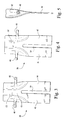
- the core 38 has a generally "pants-leg" shape with a solid upper body portion 40 and a pair of radially inwardly extending legs 42 and 44 in accordance with an exemplary embodiment of the invention.
- a pair of stabilizing pegs or printouts 46, 48 extend axially from opposite sides of the core while an elongated radially extending slot 54 separates the pants-leg portions 42 and 44.
- the core is curved in its solid upper portion so as to provide convex and concave surfaces (50, 52), respectively.
- the reinforcing pegs or printouts 46, 48 will be supported within aligned holes in the shell die, thus forming holes 30, 32 in the fore and aft walls of the shank portion of the cast bucket.
- the slot 50 will create the center partition 24.
- the stabilizing pegs or printouts 46, 48 By locating the stabilizing pegs or printouts 46, 48 radially below the angel wings 16, 18, sufficient room is provided so that the printouts 46, 48 may be directly across from one another, i.e., aligned both axially and radially. After the casting process is completed, and the core removed, holes 30, 32 remain in the bucket and must be plugged. By laterally aligning the holes 30, 32, plugs can be inserted and press fit simultaneously in the holes 30, 32 from opposite directions, without creating any asymmetrical stresses on the bucket.
- the stabilizing pegs or printouts 46, 48 have a cross sectional shape that is elliptical.
- the elliptical cross-sectional shape reduces stress at the intersection of the printouts and respective ends of the core by eliminating flat surfaces.
- the elliptical holes may be redrilled to a round shape and plugged with cylindrical plugs.
Landscapes
- Engineering & Computer Science (AREA)
- Mechanical Engineering (AREA)
- Molds, Cores, And Manufacturing Methods Thereof (AREA)
- Turbine Rotor Nozzle Sealing (AREA)
Abstract
Description
- This invention relates generally to the casting of perimeter-cooled buckets for a gas turbine and, more specifically, to a stabilization device for an internal core used in the bucket casting process.
- In an effort to improve the cooling scheme of a stage 1 gas turbine bucket, a "pants-leg" shaped core has been used in the bucket shank portion of the shell die to form a pair of cooling passages in place of a previous design utilized to form a plurality of radial cooling holes. In the casting process, however, the core tended to drift significantly, resulting in wall thicknesses in the shank portion of the bucket being out of tolerance.
- Core stabilizing devices or "printouts" for improving the yield of a bucket casting process have been previously used in stage 2 buckets, but with a different core design and in a different location relative to the so-called angel wings on the exterior of the shank portion of the bucket. Because of the different design of the stage 1 and stage 2 buckets, it was not possible to simply scale up the stage 2 bucket core for use in the stage 1 bucket casting process.
- This invention provides stabilization devices on the core used for casting stage 1 gas turbine buckets. Because of the interior configuration of the shank portion of the bucket, and in light of the desire to have the stabilizing devices laterally aligned, it was necessary to move the stabilizing devices or printouts radially downwardly in the shell die so as to be located below the external angel wings of the cast bucket.
- It is also a feature of the present invention that the cross sectional shape of the stabilization devices or printouts is of elliptical rather than the oblong or rounded rectangular shape used with the printouts for the casting of stage 2 buckets. By making the printouts elliptical in cross-sectional shape, the flat surfaces of the prior design have been eliminated, and stresses, particularly at the intersection of the printouts and the core, have been reduced.
- Accordingly, in one aspect, the present invention relates to a core for use in casting a gas turbine bucket, the core comprising a solid upper body portion and a pair of legs extending downwardly from the solid upper body portion, the pair of legs separated by an elongated slot, and a pair of pegs projecting axially from opposite sides of the upper body portion, above the elongated slot but spaced from an upper edge of the upper body portion.
- In another aspect, the invention relates to a core for use in casting a gas turbine bucket, the core comprising a solid upper body portion and a pair of legs extending downwardly from the solid upper body portion, the pair of legs separated by an elongated slot, and a pair of pegs projecting axially from opposite sides of the upper body portion, above the elongated slot but spaced from an upper edge of the upper body portion, and wherein the pegs are elliptical in cross section.
- In still another aspect, the invention relates to a method of controlling wall thickness in the shank portion of a turbine bucket during casting comprising: a) providing a core comprising a solid upper body portion and a pair of legs extending downwardly from the solid upper body portion, the legs separated by an elongated slot; b) supporting the core within a shell die by a pair of laterally aligned pegs extending from opposite ends of the solid upper body portion, the pegs located above the slot and below an upper edge of the upper body portion.
- The invention will now be described in connection with the drawings identified below, in which:
- FIGURE 1 is a partial cross section of a shank portion of a stage 1 bucket cast n accordance with the invention;
- FIGURE 2 is a perspective view of a core used in casting the bucket shown in Figure 1;
- FIGURE 3 is a front elevation of the core shown in Figure 2;
- FIGURE 4 is a rear elevation of the core shown in Figure 1;
- FIGURE 5 is a side elevation of the core shown in Figures 2-4.
-
- With reference to Figure 1, a stage 1
turbine bucket 10 includes anairfoil portion 12 and a shank portion orshank 14. The shank includes a plurality of so-calledangel wings hollow space 22, with acentral divider 24 that establishes side-by-side cooling passages Elliptical holes aft shank walls - Turning to Figures 2-5, the
core 38 has a generally "pants-leg" shape with a solidupper body portion 40 and a pair of radially inwardly extendinglegs printouts slot 54 separates the pants-leg portions - It will be appreciated that in the casting process, the reinforcing pegs or
printouts holes slot 50 will create thecenter partition 24. - By locating the stabilizing pegs or
printouts angel wings printouts holes holes holes - It is also a feature of this invention, as best seen in Figure 5, that the stabilizing pegs or
printouts
Claims (10)
- A core for use in casting a gas turbine bucket, the core comprising a solid upper body portion and a pair of legs extending downwardly from said solid upper body portion, said pair of legs separated by an elongated slot, and a pair of pegs projecting axially from opposite sides of the upper body portion, above said elongated slot but spaced from an upper edge of said upper body portion.
- The core of claim 1 wherein said solid upper body portion is curved, forming opposite concave and convex surfaces, and said legs are substantially planar, said pegs extending from the convex surface of said solid upper body portion.
- The core of claim 1 wherein said pegs are elliptical in cross section.
- The core of claim 2 wherein said pegs are elliptical in cross section.
- The core of claim 1 wherein said solid upper body portion has an upper edge, and further wherein, in a radial direction, said pegs are closer to said elongated slot than to said upper edge.
- The core of claim 1 wherein said pegs are laterally aligned.
- A core for use in casting a gas turbine bucket, the core comprising a solid upper body portion and a pair of legs extending downwardly from said solid upper body portion, said pair of legs separated by an elongated slot, and a pair of pegs projecting axially from opposite sides of the upper body portion, above said elongated slot but spaced from an upper edge of said upper body portion; and wherein said pegs are elliptical in cross section.
- The core of claim 7 wherein said solid upper body portion is curved, forming opposite concave and convex surfaces, and said legs are substantially planar, said pegs extending from the convex surface of said solid upper body portion.
- The core of claim 6 wherein said pegs are substantially laterally aligned.
- A method of controlling wall thickness in the shank portion of a turbine bucket during casting comprising:a) providing a core comprising a solid upper body portion and a pair of legs extending downwardly from said solid upper body portion, said legs separated by an elongated slot;b) supporting the core within a shell die by a pair of laterally aligned pegs extending from opposite ends of the solid upper body portion, said pegs located above said slot and below an upper edge of said upper body portion.
Applications Claiming Priority (2)
| Application Number | Priority Date | Filing Date | Title |
|---|---|---|---|
| US604220 | 2003-07-01 | ||
| US10/604,220 US20050000674A1 (en) | 2003-07-01 | 2003-07-01 | Perimeter-cooled stage 1 bucket core stabilizing device and related method |
Publications (2)
| Publication Number | Publication Date |
|---|---|
| EP1493513A1 true EP1493513A1 (en) | 2005-01-05 |
| EP1493513B1 EP1493513B1 (en) | 2012-08-15 |
Family
ID=33435344
Family Applications (1)
| Application Number | Title | Priority Date | Filing Date |
|---|---|---|---|
| EP04253927A Expired - Lifetime EP1493513B1 (en) | 2003-07-01 | 2004-06-30 | Turbine bucket core stabilizing device and related method |
Country Status (4)
| Country | Link |
|---|---|
| US (2) | US20050000674A1 (en) |
| EP (1) | EP1493513B1 (en) |
| JP (1) | JP5080720B2 (en) |
| CN (1) | CN100358655C (en) |
Cited By (2)
| Publication number | Priority date | Publication date | Assignee | Title |
|---|---|---|---|---|
| FR2933884A1 (en) * | 2008-07-16 | 2010-01-22 | Snecma | PROCESS FOR MANUFACTURING AN AUBING PIECE |
| WO2015195110A1 (en) * | 2014-06-18 | 2015-12-23 | Siemens Energy, Inc. | Turbine blade investment casting using film hole protrusions for integral wall thickness control |
Families Citing this family (8)
| Publication number | Priority date | Publication date | Assignee | Title |
|---|---|---|---|---|
| FR2871398B1 (en) * | 2004-06-15 | 2006-09-29 | Snecma Moteurs Sa | METHOD FOR MANUFACTURING A TURBINE STATOR CASTER |
| JP4619932B2 (en) * | 2005-11-30 | 2011-01-26 | 本田技研工業株式会社 | Body frame, die cast casting, die casting die, die casting method |
| US8813812B2 (en) * | 2010-02-25 | 2014-08-26 | Siemens Energy, Inc. | Turbine component casting core with high resolution region |
| US20110204205A1 (en) * | 2010-02-25 | 2011-08-25 | Ahmed Kamel | Casting core for turbine engine components and method of making the same |
| CN104325081B (en) * | 2014-10-30 | 2016-04-06 | 西安航空动力股份有限公司 | The preparation method of the combined type shell of insulation material is implanted in a kind of inside |
| CN104325090B (en) * | 2014-11-24 | 2016-05-18 | 沈阳黎明航空发动机(集团)有限责任公司 | A kind of localization method of block cast covering plate structure turbo blade ceramic core |
| CN112705671B (en) * | 2020-12-10 | 2022-03-15 | 中国科学院金属研究所 | A wax mold mold structure of a single crystal blade with a cover plate integrally cast and a cantilever structure |
| CN113070454A (en) * | 2021-03-16 | 2021-07-06 | 贵阳航发精密铸造有限公司 | Casting device and method for non-preferred orientation single crystal guide hollow blade |
Citations (4)
| Publication number | Priority date | Publication date | Assignee | Title |
|---|---|---|---|---|
| US3981344A (en) * | 1974-08-21 | 1976-09-21 | United Technologies Corporation | Investment casting mold and process |
| US4302153A (en) * | 1979-02-01 | 1981-11-24 | Rolls-Royce Limited | Rotor blade for a gas turbine engine |
| GB2346340A (en) * | 1999-02-03 | 2000-08-09 | Rolls Royce Plc | A ceramic core, a disposable pattern, a method of making a disposable pattern, a method of making a ceramic shell mould and a method of casting |
| US20040094287A1 (en) * | 2002-11-15 | 2004-05-20 | General Electric Company | Elliptical core support and plug for a turbine bucket |
Family Cites Families (21)
| Publication number | Priority date | Publication date | Assignee | Title |
|---|---|---|---|---|
| ZA745190B (en) * | 1973-11-16 | 1975-08-27 | United Aircraft Corp | Mold and process for casting high temperature alloys |
| US4023251A (en) * | 1975-07-30 | 1977-05-17 | General Electric Company | Method of manufacture of cooled turbine or compressor buckets |
| US4023249A (en) * | 1975-09-25 | 1977-05-17 | General Electric Company | Method of manufacture of cooled turbine or compressor buckets |
| US4040159A (en) * | 1975-10-29 | 1977-08-09 | General Electric Company | Method of manufacture of cooled airfoil-shaped bucket |
| US4017210A (en) * | 1976-02-19 | 1977-04-12 | General Electric Company | Liquid-cooled turbine bucket with integral distribution and metering system |
| US4183456A (en) * | 1977-04-06 | 1980-01-15 | General Electric Company | Method of fabricating liquid cooled gas turbine components |
| US4185369A (en) * | 1978-03-22 | 1980-01-29 | General Electric Company | Method of manufacture of cooled turbine or compressor buckets |
| US4283835A (en) * | 1980-04-02 | 1981-08-18 | United Technologies Corporation | Cambered core positioning for injection molding |
| US4497613A (en) * | 1983-01-26 | 1985-02-05 | General Electric Company | Tapered core exit for gas turbine bucket |
| JPS60136838A (en) * | 1983-12-26 | 1985-07-20 | Nec Corp | Information storage device |
| JPS63163229A (en) * | 1986-12-26 | 1988-07-06 | Matsushita Electric Ind Co Ltd | light temperature sensor |
| US5947181A (en) * | 1996-07-10 | 1999-09-07 | General Electric Co. | Composite, internal reinforced ceramic cores and related methods |
| US5950705A (en) * | 1996-12-03 | 1999-09-14 | General Electric Company | Method for casting and controlling wall thickness |
| US6467534B1 (en) * | 1997-10-06 | 2002-10-22 | General Electric Company | Reinforced ceramic shell molds, and related processes |
| JP2000265802A (en) | 1999-01-25 | 2000-09-26 | General Electric Co <Ge> | Gas turbine blade cooling passage connection |
| US6340047B1 (en) * | 1999-03-22 | 2002-01-22 | General Electric Company | Core tied cast airfoil |
| US6234753B1 (en) * | 1999-05-24 | 2001-05-22 | General Electric Company | Turbine airfoil with internal cooling |
| EP1106280B1 (en) * | 1999-12-08 | 2007-03-07 | General Electric Company | Core to control turbine bucket wall thickness and method |
| US6390774B1 (en) * | 2000-02-02 | 2002-05-21 | General Electric Company | Gas turbine bucket cooling circuit and related process |
| EP1127635A1 (en) * | 2000-02-25 | 2001-08-29 | Siemens Aktiengesellschaft | Apparatus and method for casting a workpiece and workpiece |
| EP1188500B1 (en) * | 2000-09-14 | 2006-08-16 | Siemens Aktiengesellschaft | Apparatus and method for producing a turbine blade and turbine blade |
-
2003
- 2003-07-01 US US10/604,220 patent/US20050000674A1/en not_active Abandoned
-
2004
- 2004-06-29 JP JP2004190616A patent/JP5080720B2/en not_active Expired - Fee Related
- 2004-06-30 EP EP04253927A patent/EP1493513B1/en not_active Expired - Lifetime
- 2004-07-01 CN CNB200410062926XA patent/CN100358655C/en not_active Expired - Fee Related
-
2006
- 2006-11-29 US US11/605,457 patent/US7467655B2/en not_active Expired - Lifetime
Patent Citations (4)
| Publication number | Priority date | Publication date | Assignee | Title |
|---|---|---|---|---|
| US3981344A (en) * | 1974-08-21 | 1976-09-21 | United Technologies Corporation | Investment casting mold and process |
| US4302153A (en) * | 1979-02-01 | 1981-11-24 | Rolls-Royce Limited | Rotor blade for a gas turbine engine |
| GB2346340A (en) * | 1999-02-03 | 2000-08-09 | Rolls Royce Plc | A ceramic core, a disposable pattern, a method of making a disposable pattern, a method of making a ceramic shell mould and a method of casting |
| US20040094287A1 (en) * | 2002-11-15 | 2004-05-20 | General Electric Company | Elliptical core support and plug for a turbine bucket |
Cited By (3)
| Publication number | Priority date | Publication date | Assignee | Title |
|---|---|---|---|---|
| FR2933884A1 (en) * | 2008-07-16 | 2010-01-22 | Snecma | PROCESS FOR MANUFACTURING AN AUBING PIECE |
| WO2015195110A1 (en) * | 2014-06-18 | 2015-12-23 | Siemens Energy, Inc. | Turbine blade investment casting using film hole protrusions for integral wall thickness control |
| US10022790B2 (en) | 2014-06-18 | 2018-07-17 | Siemens Aktiengesellschaft | Turbine airfoil cooling system with leading edge impingement cooling system turbine blade investment casting using film hole protrusions for integral wall thickness control |
Also Published As
| Publication number | Publication date |
|---|---|
| CN1575885A (en) | 2005-02-09 |
| US20050000674A1 (en) | 2005-01-06 |
| US20070131379A1 (en) | 2007-06-14 |
| JP2005021986A (en) | 2005-01-27 |
| CN100358655C (en) | 2008-01-02 |
| JP5080720B2 (en) | 2012-11-21 |
| EP1493513B1 (en) | 2012-08-15 |
| US7467655B2 (en) | 2008-12-23 |
Similar Documents
| Publication | Publication Date | Title |
|---|---|---|
| US7857588B2 (en) | Reinforced airfoils | |
| EP1493513B1 (en) | Turbine bucket core stabilizing device and related method | |
| KR100526088B1 (en) | Turbine blade | |
| US7731481B2 (en) | Airfoil cooling with staggered refractory metal core microcircuits | |
| US8353329B2 (en) | Ceramic core tapered trip strips | |
| EP1035302A3 (en) | Multiple impingement airfoil cooling | |
| US20080169412A1 (en) | Investment casting cores and methods | |
| EP1616642A1 (en) | Investment casting | |
| US7562691B2 (en) | Core for turbomachine blades | |
| EP2892671A1 (en) | Ceramic and refractory metal core assembly | |
| EP1923152A1 (en) | Airfoil casting methods | |
| US9132476B2 (en) | Multi-wall gas turbine airfoil cast using a ceramic core formed with a fugitive insert and method of manufacturing same | |
| JP2008031995A (en) | Method for reducing stress in a turbine bucket | |
| EP0829619A1 (en) | Bowed airfoil | |
| EP3825031B1 (en) | Method and apparatus for casting a turbine blade | |
| EP1013881A3 (en) | Coolable airfoils | |
| US10081052B2 (en) | Casting of engine parts | |
| US20050230077A1 (en) | Casting process and cast product | |
| JP2002021634A (en) | Crankshaft bearing for internal combustion engines | |
| EP4667132A1 (en) | Core firing setter and method of firing ceramic core | |
| JPH03264308A (en) | Tire mold | |
| JP2002224795A (en) | Cylinder head manufacturing method | |
| JP2003112234A (en) | Mold dies and air bleeding blocks for molds |
Legal Events
| Date | Code | Title | Description |
|---|---|---|---|
| PUAI | Public reference made under article 153(3) epc to a published international application that has entered the european phase |
Free format text: ORIGINAL CODE: 0009012 |
|
| AK | Designated contracting states |
Kind code of ref document: A1 Designated state(s): AT BE BG CH CY CZ DE DK EE ES FI FR GB GR HU IE IT LI LU MC NL PL PT RO SE SI SK TR |
|
| AX | Request for extension of the european patent |
Extension state: AL HR LT LV MK |
|
| 17P | Request for examination filed |
Effective date: 20050705 |
|
| AKX | Designation fees paid |
Designated state(s): CH DE FR GB LI |
|
| 17Q | First examination report despatched |
Effective date: 20091103 |
|
| GRAP | Despatch of communication of intention to grant a patent |
Free format text: ORIGINAL CODE: EPIDOSNIGR1 |
|
| GRAS | Grant fee paid |
Free format text: ORIGINAL CODE: EPIDOSNIGR3 |
|
| GRAA | (expected) grant |
Free format text: ORIGINAL CODE: 0009210 |
|
| AK | Designated contracting states |
Kind code of ref document: B1 Designated state(s): CH DE FR GB LI |
|
| REG | Reference to a national code |
Ref country code: GB Ref legal event code: FG4D Ref country code: CH Ref legal event code: EP |
|
| REG | Reference to a national code |
Ref country code: CH Ref legal event code: NV Representative=s name: SERVOPATENT GMBH |
|
| REG | Reference to a national code |
Ref country code: DE Ref legal event code: R096 Ref document number: 602004038896 Country of ref document: DE Effective date: 20121011 |
|
| PLBE | No opposition filed within time limit |
Free format text: ORIGINAL CODE: 0009261 |
|
| STAA | Information on the status of an ep patent application or granted ep patent |
Free format text: STATUS: NO OPPOSITION FILED WITHIN TIME LIMIT |
|
| 26N | No opposition filed |
Effective date: 20130516 |
|
| REG | Reference to a national code |
Ref country code: DE Ref legal event code: R097 Ref document number: 602004038896 Country of ref document: DE Effective date: 20130516 |
|
| REG | Reference to a national code |
Ref country code: FR Ref legal event code: PLFP Year of fee payment: 13 |
|
| REG | Reference to a national code |
Ref country code: FR Ref legal event code: PLFP Year of fee payment: 14 |
|
| REG | Reference to a national code |
Ref country code: FR Ref legal event code: PLFP Year of fee payment: 15 |
|
| REG | Reference to a national code |
Ref country code: CH Ref legal event code: PCAR Free format text: NEW ADDRESS: WANNERSTRASSE 9/1, 8045 ZUERICH (CH) |
|
| PGFP | Annual fee paid to national office [announced via postgrant information from national office to epo] |
Ref country code: FR Payment date: 20200520 Year of fee payment: 17 Ref country code: DE Payment date: 20200519 Year of fee payment: 17 Ref country code: CH Payment date: 20200525 Year of fee payment: 17 |
|
| PGFP | Annual fee paid to national office [announced via postgrant information from national office to epo] |
Ref country code: GB Payment date: 20200525 Year of fee payment: 17 |
|
| REG | Reference to a national code |
Ref country code: DE Ref legal event code: R119 Ref document number: 602004038896 Country of ref document: DE |
|
| REG | Reference to a national code |
Ref country code: CH Ref legal event code: PL |
|
| GBPC | Gb: european patent ceased through non-payment of renewal fee |
Effective date: 20210630 |
|
| PG25 | Lapsed in a contracting state [announced via postgrant information from national office to epo] |
Ref country code: LI Free format text: LAPSE BECAUSE OF NON-PAYMENT OF DUE FEES Effective date: 20210630 Ref country code: GB Free format text: LAPSE BECAUSE OF NON-PAYMENT OF DUE FEES Effective date: 20210630 Ref country code: DE Free format text: LAPSE BECAUSE OF NON-PAYMENT OF DUE FEES Effective date: 20220101 Ref country code: CH Free format text: LAPSE BECAUSE OF NON-PAYMENT OF DUE FEES Effective date: 20210630 |
|
| PG25 | Lapsed in a contracting state [announced via postgrant information from national office to epo] |
Ref country code: FR Free format text: LAPSE BECAUSE OF NON-PAYMENT OF DUE FEES Effective date: 20210630 |