EP1493467A2 - An exercise machine - Google Patents
An exercise machine Download PDFInfo
- Publication number
- EP1493467A2 EP1493467A2 EP04425407A EP04425407A EP1493467A2 EP 1493467 A2 EP1493467 A2 EP 1493467A2 EP 04425407 A EP04425407 A EP 04425407A EP 04425407 A EP04425407 A EP 04425407A EP 1493467 A2 EP1493467 A2 EP 1493467A2
- Authority
- EP
- European Patent Office
- Prior art keywords
- machine according
- user
- upright
- frame
- pair
- Prior art date
- Legal status (The legal status is an assumption and is not a legal conclusion. Google has not performed a legal analysis and makes no representation as to the accuracy of the status listed.)
- Granted
Links
Images


Classifications
-
- A—HUMAN NECESSITIES
- A63—SPORTS; GAMES; AMUSEMENTS
- A63B—APPARATUS FOR PHYSICAL TRAINING, GYMNASTICS, SWIMMING, CLIMBING, OR FENCING; BALL GAMES; TRAINING EQUIPMENT
- A63B24/00—Electric or electronic controls for exercising apparatus of preceding groups; Controlling or monitoring of exercises, sportive games, training or athletic performances
-
- A—HUMAN NECESSITIES
- A63—SPORTS; GAMES; AMUSEMENTS
- A63B—APPARATUS FOR PHYSICAL TRAINING, GYMNASTICS, SWIMMING, CLIMBING, OR FENCING; BALL GAMES; TRAINING EQUIPMENT
- A63B21/00—Exercising apparatus for developing or strengthening the muscles or joints of the body by working against a counterforce, with or without measuring devices
- A63B21/15—Arrangements for force transmissions
- A63B21/151—Using flexible elements for reciprocating movements, e.g. ropes or chains
- A63B21/154—Using flexible elements for reciprocating movements, e.g. ropes or chains using special pulley-assemblies
- A63B21/156—Using flexible elements for reciprocating movements, e.g. ropes or chains using special pulley-assemblies the position of the pulleys being variable, e.g. for different exercises
-
- A—HUMAN NECESSITIES
- A63—SPORTS; GAMES; AMUSEMENTS
- A63B—APPARATUS FOR PHYSICAL TRAINING, GYMNASTICS, SWIMMING, CLIMBING, OR FENCING; BALL GAMES; TRAINING EQUIPMENT
- A63B21/00—Exercising apparatus for developing or strengthening the muscles or joints of the body by working against a counterforce, with or without measuring devices
- A63B21/28—Devices for two persons operating in opposition or in cooperation
-
- A—HUMAN NECESSITIES
- A63—SPORTS; GAMES; AMUSEMENTS
- A63B—APPARATUS FOR PHYSICAL TRAINING, GYMNASTICS, SWIMMING, CLIMBING, OR FENCING; BALL GAMES; TRAINING EQUIPMENT
- A63B21/00—Exercising apparatus for developing or strengthening the muscles or joints of the body by working against a counterforce, with or without measuring devices
- A63B21/40—Interfaces with the user related to strength training; Details thereof
- A63B21/4041—Interfaces with the user related to strength training; Details thereof characterised by the movements of the interface
- A63B21/4047—Pivoting movement
-
- A—HUMAN NECESSITIES
- A63—SPORTS; GAMES; AMUSEMENTS
- A63B—APPARATUS FOR PHYSICAL TRAINING, GYMNASTICS, SWIMMING, CLIMBING, OR FENCING; BALL GAMES; TRAINING EQUIPMENT
- A63B23/00—Exercising apparatus specially adapted for particular parts of the body
- A63B23/035—Exercising apparatus specially adapted for particular parts of the body for limbs, i.e. upper or lower limbs, e.g. simultaneously
- A63B23/03516—For both arms together or both legs together; Aspects related to the co-ordination between right and left side limbs of a user
- A63B23/03525—Supports for both feet or both hands performing simultaneously the same movement, e.g. single pedal or single handle
-
- A—HUMAN NECESSITIES
- A63—SPORTS; GAMES; AMUSEMENTS
- A63B—APPARATUS FOR PHYSICAL TRAINING, GYMNASTICS, SWIMMING, CLIMBING, OR FENCING; BALL GAMES; TRAINING EQUIPMENT
- A63B23/00—Exercising apparatus specially adapted for particular parts of the body
- A63B23/035—Exercising apparatus specially adapted for particular parts of the body for limbs, i.e. upper or lower limbs, e.g. simultaneously
- A63B23/03516—For both arms together or both legs together; Aspects related to the co-ordination between right and left side limbs of a user
- A63B23/03533—With separate means driven by each limb, i.e. performing different movements
-
- A—HUMAN NECESSITIES
- A63—SPORTS; GAMES; AMUSEMENTS
- A63B—APPARATUS FOR PHYSICAL TRAINING, GYMNASTICS, SWIMMING, CLIMBING, OR FENCING; BALL GAMES; TRAINING EQUIPMENT
- A63B23/00—Exercising apparatus specially adapted for particular parts of the body
- A63B23/035—Exercising apparatus specially adapted for particular parts of the body for limbs, i.e. upper or lower limbs, e.g. simultaneously
- A63B23/0355—A single apparatus used for either upper or lower limbs, i.e. with a set of support elements driven either by the upper or the lower limb or limbs
-
- A—HUMAN NECESSITIES
- A63—SPORTS; GAMES; AMUSEMENTS
- A63B—APPARATUS FOR PHYSICAL TRAINING, GYMNASTICS, SWIMMING, CLIMBING, OR FENCING; BALL GAMES; TRAINING EQUIPMENT
- A63B23/00—Exercising apparatus specially adapted for particular parts of the body
- A63B23/035—Exercising apparatus specially adapted for particular parts of the body for limbs, i.e. upper or lower limbs, e.g. simultaneously
- A63B23/04—Exercising apparatus specially adapted for particular parts of the body for limbs, i.e. upper or lower limbs, e.g. simultaneously for lower limbs
- A63B23/0482—Exercising apparatus specially adapted for particular parts of the body for limbs, i.e. upper or lower limbs, e.g. simultaneously for lower limbs primarily by articulating the hip joints
- A63B23/0488—Exercising apparatus specially adapted for particular parts of the body for limbs, i.e. upper or lower limbs, e.g. simultaneously for lower limbs primarily by articulating the hip joints by spreading the legs
-
- A—HUMAN NECESSITIES
- A63—SPORTS; GAMES; AMUSEMENTS
- A63B—APPARATUS FOR PHYSICAL TRAINING, GYMNASTICS, SWIMMING, CLIMBING, OR FENCING; BALL GAMES; TRAINING EQUIPMENT
- A63B23/00—Exercising apparatus specially adapted for particular parts of the body
- A63B23/035—Exercising apparatus specially adapted for particular parts of the body for limbs, i.e. upper or lower limbs, e.g. simultaneously
- A63B23/12—Exercising apparatus specially adapted for particular parts of the body for limbs, i.e. upper or lower limbs, e.g. simultaneously for upper limbs or related muscles, e.g. chest, upper back or shoulder muscles
- A63B23/1209—Involving a bending of elbow and shoulder joints simultaneously
-
- A—HUMAN NECESSITIES
- A63—SPORTS; GAMES; AMUSEMENTS
- A63B—APPARATUS FOR PHYSICAL TRAINING, GYMNASTICS, SWIMMING, CLIMBING, OR FENCING; BALL GAMES; TRAINING EQUIPMENT
- A63B23/00—Exercising apparatus specially adapted for particular parts of the body
- A63B23/035—Exercising apparatus specially adapted for particular parts of the body for limbs, i.e. upper or lower limbs, e.g. simultaneously
- A63B23/12—Exercising apparatus specially adapted for particular parts of the body for limbs, i.e. upper or lower limbs, e.g. simultaneously for upper limbs or related muscles, e.g. chest, upper back or shoulder muscles
- A63B23/1245—Primarily by articulating the shoulder joint
- A63B23/1254—Rotation about an axis parallel to the longitudinal axis of the body, e.g. butterfly-type exercises
-
- A—HUMAN NECESSITIES
- A63—SPORTS; GAMES; AMUSEMENTS
- A63B—APPARATUS FOR PHYSICAL TRAINING, GYMNASTICS, SWIMMING, CLIMBING, OR FENCING; BALL GAMES; TRAINING EQUIPMENT
- A63B22/00—Exercising apparatus specially adapted for conditioning the cardio-vascular system, for training agility or co-ordination of movements
- A63B22/0076—Rowing machines for conditioning the cardio-vascular system
- A63B2022/0082—Rowing machines for conditioning the cardio-vascular system with pivoting handlebars
-
- A—HUMAN NECESSITIES
- A63—SPORTS; GAMES; AMUSEMENTS
- A63B—APPARATUS FOR PHYSICAL TRAINING, GYMNASTICS, SWIMMING, CLIMBING, OR FENCING; BALL GAMES; TRAINING EQUIPMENT
- A63B71/00—Games or sports accessories not covered in groups A63B1/00 - A63B69/00
- A63B71/02—Games or sports accessories not covered in groups A63B1/00 - A63B69/00 for large-room or outdoor sporting games
- A63B71/023—Supports, e.g. poles
- A63B2071/025—Supports, e.g. poles on rollers or wheels
-
- A—HUMAN NECESSITIES
- A63—SPORTS; GAMES; AMUSEMENTS
- A63B—APPARATUS FOR PHYSICAL TRAINING, GYMNASTICS, SWIMMING, CLIMBING, OR FENCING; BALL GAMES; TRAINING EQUIPMENT
- A63B71/00—Games or sports accessories not covered in groups A63B1/00 - A63B69/00
- A63B71/02—Games or sports accessories not covered in groups A63B1/00 - A63B69/00 for large-room or outdoor sporting games
- A63B71/023—Supports, e.g. poles
- A63B2071/026—Supports, e.g. poles stabilised by weight
-
- A—HUMAN NECESSITIES
- A63—SPORTS; GAMES; AMUSEMENTS
- A63B—APPARATUS FOR PHYSICAL TRAINING, GYMNASTICS, SWIMMING, CLIMBING, OR FENCING; BALL GAMES; TRAINING EQUIPMENT
- A63B21/00—Exercising apparatus for developing or strengthening the muscles or joints of the body by working against a counterforce, with or without measuring devices
- A63B21/005—Exercising apparatus for developing or strengthening the muscles or joints of the body by working against a counterforce, with or without measuring devices using electromagnetic or electric force-resisters
- A63B21/0053—Exercising apparatus for developing or strengthening the muscles or joints of the body by working against a counterforce, with or without measuring devices using electromagnetic or electric force-resisters using alternators or dynamos
-
- A—HUMAN NECESSITIES
- A63—SPORTS; GAMES; AMUSEMENTS
- A63B—APPARATUS FOR PHYSICAL TRAINING, GYMNASTICS, SWIMMING, CLIMBING, OR FENCING; BALL GAMES; TRAINING EQUIPMENT
- A63B21/00—Exercising apparatus for developing or strengthening the muscles or joints of the body by working against a counterforce, with or without measuring devices
- A63B21/06—User-manipulated weights
- A63B21/062—User-manipulated weights including guide for vertical or non-vertical weights or array of weights to move against gravity forces
- A63B21/0626—User-manipulated weights including guide for vertical or non-vertical weights or array of weights to move against gravity forces with substantially vertical guiding means
- A63B21/0628—User-manipulated weights including guide for vertical or non-vertical weights or array of weights to move against gravity forces with substantially vertical guiding means for vertical array of weights
-
- A—HUMAN NECESSITIES
- A63—SPORTS; GAMES; AMUSEMENTS
- A63B—APPARATUS FOR PHYSICAL TRAINING, GYMNASTICS, SWIMMING, CLIMBING, OR FENCING; BALL GAMES; TRAINING EQUIPMENT
- A63B2220/00—Measuring of physical parameters relating to sporting activity
- A63B2220/30—Speed
-
- A—HUMAN NECESSITIES
- A63—SPORTS; GAMES; AMUSEMENTS
- A63B—APPARATUS FOR PHYSICAL TRAINING, GYMNASTICS, SWIMMING, CLIMBING, OR FENCING; BALL GAMES; TRAINING EQUIPMENT
- A63B2220/00—Measuring of physical parameters relating to sporting activity
- A63B2220/30—Speed
- A63B2220/36—Speed measurement by electric or magnetic parameters
-
- A—HUMAN NECESSITIES
- A63—SPORTS; GAMES; AMUSEMENTS
- A63B—APPARATUS FOR PHYSICAL TRAINING, GYMNASTICS, SWIMMING, CLIMBING, OR FENCING; BALL GAMES; TRAINING EQUIPMENT
- A63B2220/00—Measuring of physical parameters relating to sporting activity
- A63B2220/50—Force related parameters
- A63B2220/51—Force
-
- A—HUMAN NECESSITIES
- A63—SPORTS; GAMES; AMUSEMENTS
- A63B—APPARATUS FOR PHYSICAL TRAINING, GYMNASTICS, SWIMMING, CLIMBING, OR FENCING; BALL GAMES; TRAINING EQUIPMENT
- A63B2225/00—Miscellaneous features of sport apparatus, devices or equipment
- A63B2225/09—Adjustable dimensions
-
- A—HUMAN NECESSITIES
- A63—SPORTS; GAMES; AMUSEMENTS
- A63B—APPARATUS FOR PHYSICAL TRAINING, GYMNASTICS, SWIMMING, CLIMBING, OR FENCING; BALL GAMES; TRAINING EQUIPMENT
- A63B2225/00—Miscellaneous features of sport apparatus, devices or equipment
- A63B2225/10—Multi-station exercising machines
-
- A—HUMAN NECESSITIES
- A63—SPORTS; GAMES; AMUSEMENTS
- A63B—APPARATUS FOR PHYSICAL TRAINING, GYMNASTICS, SWIMMING, CLIMBING, OR FENCING; BALL GAMES; TRAINING EQUIPMENT
- A63B23/00—Exercising apparatus specially adapted for particular parts of the body
- A63B23/035—Exercising apparatus specially adapted for particular parts of the body for limbs, i.e. upper or lower limbs, e.g. simultaneously
- A63B23/03516—For both arms together or both legs together; Aspects related to the co-ordination between right and left side limbs of a user
- A63B23/03533—With separate means driven by each limb, i.e. performing different movements
- A63B23/03541—Moving independently from each other
Definitions
- the present invention relates to an exercise machine, preferably of isotonic type.
- the fitness sector today offers an extremely wide variety of exercise machines. These machines can be divided broadly into two categories: isotonic machines and cardiovascular machines.
- Isotonic machines normally comprise a working position for the user who uses his/her physical power to apply a force that is opposed by gravity acting on a set of passive elements forming what is normally called a weight stack.
- the working position is the location where the user places his/her body, whether seated or standing, which means that this position coincides with an area where the weight of the user's body is supported by the ground, with or without a footplate.
- Machines of this type have a portal frame which is located in a vertical plane and which accommodates a plurality of blocks, each having a predetermined weight.
- the user selects the number of blocks to be used for the required exercise, thus creating a stack of desired weight which applies the resistant force that must be overcome by the user's muscular strength; between the resistant force and the active part of the exercise apparatus there is usually a connecting element, normally consisting of a cord or cable wound several times around pulleys and designed to carry the resistant force to the point where the user must apply his/her physical power to overcome it.
- the resistant force is provided by gravity.
- more complex machines may be used in which the resistant force is produced by a motor or alternator connected to a source of electric power and providing controlled torque.
- exercise machines of this kind are designed in such a way that the user competes against himself/herself.
- the user has to perform a training protocol without any active opponent, which, in the long run, may lead to deconcentration or even refusal to perform exercises according to established rules.
- Another disadvantage is that the correct performance of the protocol depends entirely on the user and it is therefore difficult to control the uniformity of the training or to assess (unless this is done in separate stages) the individual progress of two or more trainees, such as, for example, the members of a sports team or persons required to reach a minimum fitness level.
- the present invention therefore has for an object to overcome the above mentioned disadvantages by providing an exercise machine that allows users to train not in isolation but in association with other users so as to able to interact with each other while performing an exercise.
- the advantages achieved by the invention lie essentially in the fact that the users training simultaneously on the same machine not only follow a predetermined protocol but also have the opportunity of measuring their strength against each other, thus reducing the risk of demotivation and providing a competitive stimulus to achieving the targets set by the protocol.
- Another advantage is that of permitting the activities of different trainees following the same or similar training programmes to be standardised, thus making it possible to assess the effectiveness of a programme on different individuals.
- an exercise machine in its most general configuration of kinematic components, essentially comprises the following:
- the transmission mechanism may consist wholly or partly of a set of rigid levers joined to each other and, if necessary, combined with cable mechanisms, as described in more detail below.
- the machine is preferably equipped with a load sensor designed to indicate a value (and, if necessary, a threshold) of the force load applied by the users.
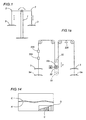
- Figure 1a schematically illustrates the connection between the user positions.
- the length of the connection can be adjusted by means of a motor M designed to move the pin 23x of a pulley 22 vertically in the direction indicated by the arrow F, thus shifting the actuators between the initial positions 3 and 3a.
- the cable 24 is also equipped with load sensors 224, load cells 226 and dampers 225.
- Figure 14 is a graph showing an example curve representing the load C applied by the user, measured by a sensor and displayed by a display unit indicated schematically by the reference letter D in Figure 14, compared to a reference level R representing the training programme, in such a way as to stimulate the users, individually and in competition with each other, to keep up with the programme.
- the invention also contemplates the possibility of a progressive indication of the load C by the display unit D or by a separate unit in order to enable the users to check the level they have reached at any point in time.
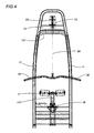
- the machine frame consists of a portal frame 11 supported at the bottom by a base 19 and having, at the top of it, a crossbeam 12 mounted in turn on a forked support 131.
- the work position of each user consists of a seat 18 and rollers 17 adjustable in height by means of a telescopic support 171 that can be locked in a desired location by a height selector block 172.
- the rollers 17 are preferably covered with soft padding and used to hold down the legs of the users sitting in the seats 18.
- the power transmission mechanism consists of a system of pulleys 22 rotating on pins 23 fixed to the crossbeam 12, and having trained around them a flexible cable 24 with a handlebar 30 at each end, preferably of ergonomic form to facilitate gripping by the users.
- one of the two users applies an active force whilst the other exerts a resistant force, if necessary according to a predetermined training protocol.
- a load sensor 241, located for example on the cable 24, indicates when the load reaches a predetermined threshold value set for safety reasons and/or as a check on the exercise being performed.
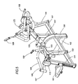
- the machine frame consists of an upturned U structure 11 supported at the bottom by a beam 101 and a crossbeam 102.
- first pair 103 being vertical and the second pair 104 being slightly inclined and upwardly converging.
- the two pairs of uprights 103, 104 are joined at the top of the frame by respective bars 105, which are slightly inclined to the horizontal and converge at the centre of the frame where they join the U structure 100.
- Each of the user work positions consists of a seat 181, adjustably mounted for height along the upright 104, and a rest 173 for the user's chest.
- the distance of the chest rest 173 from the user can be adjusted by operating on a support 174 that slides inside the bars 105 and can be locked in a desired position using customary selective lock devices 175.
- the bars 105 mount curved arms 106 facing the user position and having two joints 107 fitted at the ends of them.
- the joints 107 have pivoted on them the first ends of a pair of handlebars 108 each of which is fitted with a handle 109 at the other end.
- the handlebars 108 are mounted crossways relative to each other and can be rotated towards each other by the user.
- the power transmission mechanism consists of cables -- not illustrated in the drawings -- which start at the joints 107 and run preferably inside the components of the frame to connect, through customary pulley type devices, the pair of handlebars 108 of one user work position with the pair of handlebars 108 of the other user work position.
- the users sit in the seats 181 gripping the handles 109 and move the latter alternately to and fro, if necessary according to a predetermined training protocol.
- the users exerts an active force and pulls the handlebars 108 towards himself/herself, the other applies a resistant force to oppose this action.
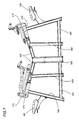
- the machine frame consists of a U-shaped structure 201 supported at the bottom by a main beam 202 and a crossbeam 203.
- each seat 205 there extend two shafts 207 which are fixed at the bottom to a transversal support 219 and about which two structures 208 rotate symmetrically in such a way as to resist the outward movement of the legs of the users sitting in the seats 205.
- each of the structures 208 consists of an approximately horizontal arm 210 which can rotate with a first end about a shaft 207 and which, at the other end, is attached to the intermediate vertical section 213 of a bar 211.
- the bar 211 has an upper horizontal section 214, to which there is fixed a rest or pad 215 for engaging the user's thighs, and a lower inclined section 216 fitted with a footrest 217.
- each seat 205 there are handles 218, which the user holds for stability, and an adjustment lever 220.
- the power transmission mechanism between the two user work positions consists of a system of cables (not illustrated in the drawings since it is of known type) that run preferably inside the components of the frame to connect the opening movement of the structures 208 of one work position to the corresponding closing movement of the levers 208 of the other work position.
- the machine frame is divided into two halves, one like the frame described above with reference to Figures 5 to 8 (the corresponding components are thus labelled with the same reference numbers) facing the other half consisting of a side upright 301 fixed at the bottom to the beam 101 and joined by an intermediate section 302 to a second upright 303, also fixed to the bottom beam 101.
- the upper end of the upright 301 has a crossbeam 309 that is curved inwardly with its concave section facing the centre of the machine.
- the user work position is mounted on the upright 303 and consists of a seat, adjustably mounted for height on the upright 303, and a backrest 305 fixed to the upright 303.
- the actuators in this case consist of a pair of arms 308 mounted crossways and able to counter-rotate about pins located at the ends of the crossbeam 309.
- the arms 308 are also fitted with customary handgrips 310.
- the power transmission mechanism consists of a pulley and cable system 311 partly installed on the crossbeam 309 and not described in any detail since it is of well known type.
- the transmission mechanism is such that, starting at the end 308 the force exerted by the user at the work position 304 is transmitted to the actuators 108 of the user position 181 and vice versa.
- the cables of the transmission mechanism may follow a different path, running preferably inside the components (preferably tubular) of the machine frame.
- the means for connecting the user positions may comprise means for adjusting the length of the connection according to the physical characteristics of the users.
- the connecting means may also include elastic means or dampers to smooth the transient effects of passing from an active force to a resistant force and vice versa.
- FIGS 16, 16a and 16b illustrate yet another embodiment of the invention.
- the machine comprises a base 401 mounting an upright 400 consisting preferably of a tube, for example with an oval cross section, acting as a guide for a work unit 404.
- the single upright structure 403 enables the users to move all the way round the machine and to change their positions relative to the actuators to perform different exercises.
- the work unit 404 slidable along the guide 403, may be fixed in position by a locking element 405, consisting, for example, of a clamp screw that moves as one with the work unit 404 and engages by contact or interference with the vertical guide 403.
- a locking element 405 consisting, for example, of a clamp screw that moves as one with the work unit 404 and engages by contact or interference with the vertical guide 403.
- the sliding work unit 404 is in turn equipped with four pairs of opposing horizontal plates 406, between which there are mounted, preferably rotating about horizontal axes, four supports 408 arranged in pairs on opposite sides of the upright 403 and each mounting a pair of pulleys 407 with horizontal axes and positioned over each other vertically.
- the rotation of the supports enables users to easily perform exercises requiring the actuators to be moved apart as well as exercises in which the users have to change their positions relative to the actuators by moving around the machine.
- the work unit 404 mounts all the pulleys 407 which are therefore adjustable as one.
- the height of the pulleys might also be adjusted independently at the two sides of the upright, in such manner as to individually vary one or both of the pulling points of one or both of the users.
- the machine also comprises two cables 412, 412' passing through respective pulleys 407, 409, 410 and actuated by opposite pairs of handles 414a / 414b and 415a / 415b operated by two users (not illustrated in the drawings) standing on opposite sides of the upright 403 at the schematically illustrated exercise positions labelled 413.
- handles might be substituted by actuators or handlebars of any kind suitable for performing the exercise.
- the cables 412, 412' constitute a twin-cable arrangement, that is to say, a double path of twin cables each of which, with reference, for example, to the cable 412, is fixed at one end to a first actuator 414a, passes through the overlaid pulleys 407 of one support 408 positioned at a first side of the upright 403 and, in succession, through the corresponding upper and lower pulleys 409 and 410 to connect up with the opposite actuator 414b after passing through the central overlaid pulleys 407 of the support 408 at the opposite side of the upright 403.
- each of the pulleys 407, 409, 410 there are two of each of the pulleys 407, 409, 410 on each side of the machine so as to enable two users to exercise both arms at the same time, but without thereby excluding the possibility of having a single pulley or more than two pulleys, according to requirements.
- the two users each in his/her exercise position 413, grip the actuators on the corresponding side of the machine, and alternately pull the two actuators (for example, 414a and 415a) in such that the two users, thanks to the path followed by the cables 412 and 412', oppose each other in alternately pulling the actuators.
- the two users may oppose or second each other in performing different types of exercises for the purposes of muscular strengthening, cardiovascular training, muscular stretching or even proprioceptive training in which one of the two users tests the balance of the other.
- the point and angle at which the cable is pulled outwards can be varied according to the type of exercise and to the part of the body to be exercised.
- the length of the cables 412 / 412' pulled out of the machine can be adjusted to suit the type of exercise which the users have to perform, and according to the distance from the machine required by the exercise.
- the length of the cable 412/412' that can be pulled out of the machine can be adjusted by making the cable follow a path such that, on leaving the lower pulley 410, it winds one or more times around a corresponding pulley 419, mounted on idle rollers on the upright 403 and then proceeds along the path described above towards the upper pulley 409 and from there to the opposite actuator.
- each turn around the pulley 419 corresponds to a reduction of the active length of the cable 412/412', that is to say, the extent to which the cable can be pulled out of the machine using the opposite actuator 414a,b and 415a,b.
- the upper pulleys 409 are mounted in a protective guard 427 and are connected to a dynamo 423 which powers a lamp 422 located above the user work positions 413.
- the lamp When the lamp switches on, it provides an indication of the speed at which the exercise is being carried out and may also constitute a performance target to be achieved.
- the base 401 which must normally have a certain weight to guarantee machine stability, may consist of a hollow container 426 equipped with a filler opening 425, so that the machine itself is relatively light for transportation purposes but, once positioned, can be weighted down by filling the container with liquid (or sand or other suitable material) to increase the stability of the machine during use.
- the machine of Figure 16 may also be equipped with wheels 424 fitted to the edge of the base 401 slightly off the ground so as to touch the ground only if the upright 403 is tilted to enable it to be moved from one place to another.
- an additional resistant force consisting, for example, of traditional weights, may be applied to one or both sides of the machine besides the alternate active / resistant force applied by the users. This would compensate for excessive differences in strength between the two users.
- Figures 15a and 14b schematically illustrate a machine according to the invention in which a set of weights P, variable in number and composition according to requirements, is applied to one of two user positions.
- the weights are positioned close to one of the actuators 3, so as to increase the resistant force applied to the other actuator.
- the pulleys of the additional system have two grooves so that the actuator concerned is connected to the other actuator through a first cable 24 passing around one groove in the pulleys 22 and to the weight stack P through a second cable passing around the other groove in the same pulleys.
- the weight stack P may be varied according to requirements and may be applied to one or both user positions.
- Figure 15b also shows a load cell CC advantageously applied to a point 29 where one of the pulleys 22 is fixed to the frame 1.
- the load cell is applied to the point where the pulley located at the centre of symmetry is attached to the frame but it may be fitted at any other suitable position.
- This solution offers the advantage of measuring the load in a structurally and functionally simple manner.
Abstract
Description
- The present invention relates to an exercise machine, preferably of isotonic type.
- The fitness sector today offers an extremely wide variety of exercise machines. These machines can be divided broadly into two categories: isotonic machines and cardiovascular machines.
- Isotonic machines normally comprise a working position for the user who uses his/her physical power to apply a force that is opposed by gravity acting on a set of passive elements forming what is normally called a weight stack.
- In the present invention, the working position is the location where the user places his/her body, whether seated or standing, which means that this position coincides with an area where the weight of the user's body is supported by the ground, with or without a footplate.
- Machines of this type have a portal frame which is located in a vertical plane and which accommodates a plurality of blocks, each having a predetermined weight. The user selects the number of blocks to be used for the required exercise, thus creating a stack of desired weight which applies the resistant force that must be overcome by the user's muscular strength; between the resistant force and the active part of the exercise apparatus there is usually a connecting element, normally consisting of a cord or cable wound several times around pulleys and designed to carry the resistant force to the point where the user must apply his/her physical power to overcome it.
- Thus, in the above type of solution, the resistant force is provided by gravity. Alternatively, more complex machines may be used in which the resistant force is produced by a motor or alternator connected to a source of electric power and providing controlled torque.
- Whichever the solution adopted, exercise machines of this kind (as generally used for recreational, rehabilitation and similar applications) are designed in such a way that the user competes against himself/herself. In other words, the user has to perform a training protocol without any active opponent, which, in the long run, may lead to deconcentration or even refusal to perform exercises according to established rules.
- Another disadvantage is that the correct performance of the protocol depends entirely on the user and it is therefore difficult to control the uniformity of the training or to assess (unless this is done in separate stages) the individual progress of two or more trainees, such as, for example, the members of a sports team or persons required to reach a minimum fitness level.
- The present invention therefore has for an object to overcome the above mentioned disadvantages by providing an exercise machine that allows users to train not in isolation but in association with other users so as to able to interact with each other while performing an exercise.
- According to the invention, this object is achieved by an exercise machine as defined in the main appended claim.
- The advantages achieved by the invention lie essentially in the fact that the users training simultaneously on the same machine not only follow a predetermined protocol but also have the opportunity of measuring their strength against each other, thus reducing the risk of demotivation and providing a competitive stimulus to achieving the targets set by the protocol.
- Another advantage is that of permitting the activities of different trainees following the same or similar training programmes to be standardised, thus making it possible to assess the effectiveness of a programme on different individuals.
- Further advantages are achieved thanks to the characteristics defined in the dependent claims.
- The technical characteristics of the invention, with reference to the above aims, are clearly described in the claims below and its advantages are apparent from the detailed description which follows, with reference to the accompanying drawings which illustrate preferred embodiments of the invention provided merely by way of example without restricting the scope of the inventive concept, and in which:
- Figure 1 is a general diagram of an exercise machine according to the invention;
- Figure 1a is a diagram showing the connection of adjustable length between the user positions;
- Figure 2 is a perspective view of a first preferred embodiment of a machine according to the invention, belonging to the category of exercise machines generally known as "lat machines";
- Figure 3 is a front view of the machine of Figure 2;
- Figure 4 is a side view of the machine of Figure 2;
- Figure 5 is a perspective view of a second preferred embodiment of a machine according to the invention, belonging to the category of exercise machines generally known as "upper machines";
- Figure 6 is a top view of the machine of Figure 5;
- Figure 7 is a side view of the machine of Figure 5;
- Figure 8 is a perspective view of a third preferred embodiment of a machine according to the invention, belonging to the category of exercise machines generally known as "abductor machines";
- Figure 9 is a top view of the machine of Figure 8;
- Figure 10 is a side view of the machine of Figure 8;
- Figure 11 is a perspective view of a fourth preferred embodiment of a machine according to the invention, resulting from the combination of two machines, placed face to face, belonging to the categories of exercise machines generally known as "chest presses" and "upper machines";
- Figure 12 is a top view of the machine of Figure 11;
- Figure 13 is a side view of the machine of Figure 11;
- Figure 14 is a graph showing an example curve representing a load applied by the users progressively and compared to a reference level;
- Figures 15a and 15b schematically illustrate further embodiments of the machine according to the invention;
- Figures 16 and 16a-16c schematically illustrate yet another embodiment of the machine according to the invention.
- With reference to Figure 1, an exercise machine according to the invention, in its most general configuration of kinematic components, essentially comprises the following:
- a mounting
frame 1; - a reversible
power transmission mechanism 2 mounted on theframe 1; - at least two user work positions equipped with
actuators 3 operatively connected to thetransmission mechanism 2 and designed to be operated by the users who alternately and reciprocally apply an active force and a resistant force through thetransmission mechanism 2. - Advantageously, as shown in the diagram of Figure 1, the transmission mechanism may consist wholly or partly of a set of rigid levers joined to each other and, if necessary, combined with cable mechanisms, as described in more detail below.
- In all its preferred embodiments, the machine is preferably equipped with a load sensor designed to indicate a value (and, if necessary, a threshold) of the force load applied by the users.
- Figure 1a schematically illustrates the connection between the user positions. The length of the connection can be adjusted by means of a motor M designed to move the
pin 23x of apulley 22 vertically in the direction indicated by the arrow F, thus shifting the actuators between theinitial positions - Preferably, the
cable 24 is also equipped withload sensors 224, load cells 226 anddampers 225. - Figure 14 is a graph showing an example curve representing the load C applied by the user, measured by a sensor and displayed by a display unit indicated schematically by the reference letter D in Figure 14, compared to a reference level R representing the training programme, in such a way as to stimulate the users, individually and in competition with each other, to keep up with the programme.
- Still with reference to Figure 14, the invention also contemplates the possibility of a progressive indication of the load C by the display unit D or by a separate unit in order to enable the users to check the level they have reached at any point in time.
- It should be stressed that all the embodiments described below are offered purely as examples of the inventive concept without thereby limiting the possibility of extending the concept to other solutions, all falling within the scope of the appended claims. This is intended as confirmation of the possibility of extending the inventive concept to a wide range of different machines.
- With reference to the embodiment illustrated in Figures 2 to 4, the machine frame consists of a
portal frame 11 supported at the bottom by abase 19 and having, at the top of it, acrossbeam 12 mounted in turn on a forkedsupport 131. - The work position of each user consists of a
seat 18 androllers 17 adjustable in height by means of atelescopic support 171 that can be locked in a desired location by aheight selector block 172. - The
rollers 17 are preferably covered with soft padding and used to hold down the legs of the users sitting in theseats 18. - The power transmission mechanism consists of a system of
pulleys 22 rotating onpins 23 fixed to thecrossbeam 12, and having trained around them aflexible cable 24 with ahandlebar 30 at each end, preferably of ergonomic form to facilitate gripping by the users. - During use, the two users sitting in the
seats 18 with therollers 17 resting on their legs in such a way that they can grip theactuators 30 with both hands and alternately apply a force (according to a well-known training technique) which is transmitted to the other user through thecable 24. - In this way, one of the two users applies an active force whilst the other exerts a resistant force, if necessary according to a predetermined training protocol.
- Preferably, a
load sensor 241, located for example on thecable 24, indicates when the load reaches a predetermined threshold value set for safety reasons and/or as a check on the exercise being performed. - With reference to the embodiment illustrated in Figures 5 to 7, the machine frame consists of an
upturned U structure 11 supported at the bottom by abeam 101 and acrossbeam 102. - Mounted on the
beam 101 there are two pairs of uprights, thefirst pair 103 being vertical and thesecond pair 104 being slightly inclined and upwardly converging. - The two pairs of
uprights respective bars 105, which are slightly inclined to the horizontal and converge at the centre of the frame where they join theU structure 100. - Each of the user work positions consists of a
seat 181, adjustably mounted for height along the upright 104, and arest 173 for the user's chest. - The distance of the
chest rest 173 from the user can be adjusted by operating on asupport 174 that slides inside thebars 105 and can be locked in a desired position using customaryselective lock devices 175. - At the height of the
adjustable support 174, thebars 105 mount curvedarms 106 facing the user position and having twojoints 107 fitted at the ends of them. - The
joints 107 have pivoted on them the first ends of a pair ofhandlebars 108 each of which is fitted with ahandle 109 at the other end. - The
handlebars 108 are mounted crossways relative to each other and can be rotated towards each other by the user. - The power transmission mechanism consists of cables -- not illustrated in the drawings -- which start at the
joints 107 and run preferably inside the components of the frame to connect, through customary pulley type devices, the pair ofhandlebars 108 of one user work position with the pair ofhandlebars 108 of the other user work position. - During use, the users sit in the
seats 181 gripping thehandles 109 and move the latter alternately to and fro, if necessary according to a predetermined training protocol. In other terms, while one of the users exerts an active force and pulls thehandlebars 108 towards himself/herself, the other applies a resistant force to oppose this action. - With reference to the embodiment illustrated in Figures 8 to 10, the machine frame consists of a
U-shaped structure 201 supported at the bottom by amain beam 202 and acrossbeam 203. - Symmetrically mounted at the ends of the
main beam 202, there are twocurved uprights 204 each fitted with aseat 205 fixed to an upperhorizontal section 206 of the upright 204 itself. - Under each
seat 205 there extend twoshafts 207 which are fixed at the bottom to atransversal support 219 and about which twostructures 208 rotate symmetrically in such a way as to resist the outward movement of the legs of the users sitting in theseats 205. - Looking in more detail, each of the
structures 208 consists of an approximatelyhorizontal arm 210 which can rotate with a first end about ashaft 207 and which, at the other end, is attached to the intermediatevertical section 213 of a bar 211. - The bar 211 has an upper
horizontal section 214, to which there is fixed a rest or pad 215 for engaging the user's thighs, and a lowerinclined section 216 fitted with afootrest 217. - At the sides of each
seat 205 there arehandles 218, which the user holds for stability, and anadjustment lever 220. - The power transmission mechanism between the two user work positions consists of a system of cables (not illustrated in the drawings since it is of known type) that run preferably inside the components of the frame to connect the opening movement of the
structures 208 of one work position to the corresponding closing movement of thelevers 208 of the other work position. - Thus, while one user spreads his/her legs outwards against the
thigh pads 218 exerting an active force that opens thestructures 208, the other user may apply a resistant force. This exercise may form part of a predetermined training protocol. - With reference to the embodiment illustrated in Figures 11 to 13, the machine frame is divided into two halves, one like the frame described above with reference to Figures 5 to 8 (the corresponding components are thus labelled with the same reference numbers) facing the other half consisting of a side upright 301 fixed at the bottom to the
beam 101 and joined by an intermediate section 302 to asecond upright 303, also fixed to thebottom beam 101. - The upper end of the upright 301 has a
crossbeam 309 that is curved inwardly with its concave section facing the centre of the machine. - The user work position is mounted on the
upright 303 and consists of a seat, adjustably mounted for height on theupright 303, and abackrest 305 fixed to theupright 303. - The actuators in this case consist of a pair of
arms 308 mounted crossways and able to counter-rotate about pins located at the ends of thecrossbeam 309. - The
arms 308 are also fitted withcustomary handgrips 310. - The power transmission mechanism consists of a pulley and
cable system 311 partly installed on thecrossbeam 309 and not described in any detail since it is of well known type. - According to the invention, the transmission mechanism is such that, starting at the
end 308 the force exerted by the user at thework position 304 is transmitted to theactuators 108 of theuser position 181 and vice versa. - As in the other preferred embodiments described above, the cables of the transmission mechanism may follow a different path, running preferably inside the components (preferably tubular) of the machine frame.
- Moreover, in all the embodiments, the means for connecting the user positions may comprise means for adjusting the length of the connection according to the physical characteristics of the users.
- The connecting means may also include elastic means or dampers to smooth the transient effects of passing from an active force to a resistant force and vice versa.
- Figures 16, 16a and 16b illustrate yet another embodiment of the invention.
- The machine comprises a base 401 mounting an upright 400 consisting preferably of a tube, for example with an oval cross section, acting as a guide for a
work unit 404. - Advantageously, the
single upright structure 403 enables the users to move all the way round the machine and to change their positions relative to the actuators to perform different exercises. - The
work unit 404, slidable along theguide 403, may be fixed in position by alocking element 405, consisting, for example, of a clamp screw that moves as one with thework unit 404 and engages by contact or interference with thevertical guide 403. - At the
top end 420 of the upright 400 there are twopulleys 409 positioned horizontally side by side, whilst another twotransmission pulleys 410 are positioned at the bottom end, close to thebase 401. - The sliding
work unit 404 is in turn equipped with four pairs of opposinghorizontal plates 406, between which there are mounted, preferably rotating about horizontal axes, foursupports 408 arranged in pairs on opposite sides of the upright 403 and each mounting a pair ofpulleys 407 with horizontal axes and positioned over each other vertically. - Advantageously, the rotation of the supports enables users to easily perform exercises requiring the actuators to be moved apart as well as exercises in which the users have to change their positions relative to the actuators by moving around the machine.
- In the embodiment illustrated, the
work unit 404 mounts all thepulleys 407 which are therefore adjustable as one. - It will be understood, however, that the invention also contemplates that the height of the pulleys might also be adjusted independently at the two sides of the upright, in such manner as to individually vary one or both of the pulling points of one or both of the users.
- The machine also comprises two
cables 412, 412' passing throughrespective pulleys handles 414a / 414b and 415a / 415b operated by two users (not illustrated in the drawings) standing on opposite sides of the upright 403 at the schematically illustrated exercise positions labelled 413. - It will be understood that the handles might be substituted by actuators or handlebars of any kind suitable for performing the exercise.
- Looking in more detail, the
cables 412, 412' constitute a twin-cable arrangement, that is to say, a double path of twin cables each of which, with reference, for example, to thecable 412, is fixed at one end to afirst actuator 414a, passes through the overlaidpulleys 407 of onesupport 408 positioned at a first side of the upright 403 and, in succession, through the corresponding upper andlower pulleys opposite actuator 414b after passing through the central overlaid pulleys 407 of thesupport 408 at the opposite side of theupright 403. - An identical path through the corresponding central, upper and
lower pulleys actuator - In the embodiment being described, there are two of each of the
pulleys - During operation, the two users, each in his/her
exercise position 413, grip the actuators on the corresponding side of the machine, and alternately pull the two actuators (for example, 414a and 415a) in such that the two users, thanks to the path followed by thecables 412 and 412', oppose each other in alternately pulling the actuators. - On a machine constructed in this way, the two users may oppose or second each other in performing different types of exercises for the purposes of muscular strengthening, cardiovascular training, muscular stretching or even proprioceptive training in which one of the two users tests the balance of the other.
- Further, thanks to the adjustability of the vertical position of the
work unit 404 and to the rotatability of thesupports 408, the point and angle at which the cable is pulled outwards, that is to say, the direction of the force applied by the users, can be varied according to the type of exercise and to the part of the body to be exercised. - It follows that the upper or the lower pulley in the pairs of
pulleys 407 mounted on thework unit 404 is activated according to the position of the work unit relative to the user's grip. - Further, the length of the
cables 412 / 412' pulled out of the machine can be adjusted to suit the type of exercise which the users have to perform, and according to the distance from the machine required by the exercise. - Looking in more detail, the length of the
cable 412/412' that can be pulled out of the machine can be adjusted by making the cable follow a path such that, on leaving thelower pulley 410, it winds one or more times around a correspondingpulley 419, mounted on idle rollers on theupright 403 and then proceeds along the path described above towards theupper pulley 409 and from there to the opposite actuator. - With this solution, each turn around the
pulley 419 corresponds to a reduction of the active length of thecable 412/412', that is to say, the extent to which the cable can be pulled out of the machine using theopposite actuator 414a,b and 415a,b. - According to another characteristic of the machine, the
upper pulleys 409 are mounted in aprotective guard 427 and are connected to adynamo 423 which powers alamp 422 located above the user work positions 413. - When the lamp switches on, it provides an indication of the speed at which the exercise is being carried out and may also constitute a performance target to be achieved.
- In addition, the
base 401, which must normally have a certain weight to guarantee machine stability, may consist of ahollow container 426 equipped with afiller opening 425, so that the machine itself is relatively light for transportation purposes but, once positioned, can be weighted down by filling the container with liquid (or sand or other suitable material) to increase the stability of the machine during use. To facilitate handling, the machine of Figure 16 may also be equipped withwheels 424 fitted to the edge of the base 401 slightly off the ground so as to touch the ground only if the upright 403 is tilted to enable it to be moved from one place to another. - In the embodiments described above, an additional resistant force, consisting, for example, of traditional weights, may be applied to one or both sides of the machine besides the alternate active / resistant force applied by the users. This would compensate for excessive differences in strength between the two users.
- By way of example, Figures 15a and 14b schematically illustrate a machine according to the invention in which a set of weights P, variable in number and composition according to requirements, is applied to one of two user positions.
- In the embodiment of Figure 15a, the weights are positioned close to one of the
actuators 3, so as to increase the resistant force applied to the other actuator. - In Figure 15b the weights P are applied to one of the two actuators by means of an additional system of
cables 24 and pulleys 22. - Looking in more detail at the embodiment illustrated in Figure 15b, the pulleys of the additional system have two grooves so that the actuator concerned is connected to the other actuator through a
first cable 24 passing around one groove in thepulleys 22 and to the weight stack P through a second cable passing around the other groove in the same pulleys. - Obviously, the weight stack P may be varied according to requirements and may be applied to one or both user positions.
- Figure 15b also shows a load cell CC advantageously applied to a point 29 where one of the
pulleys 22 is fixed to theframe 1. - In this case, the load cell is applied to the point where the pulley located at the centre of symmetry is attached to the frame but it may be fitted at any other suitable position.
- This solution offers the advantage of measuring the load in a structurally and functionally simple manner.
- The invention described has evident industrial applications and can be subject to modifications and variations without thereby departing from the scope of the inventive concept. Moreover, all the details of the invention may be substituted by technically equivalent elements.
Claims (29)
- An exercise machine comprising: a mounting frame (1); at least two user positions (18, 181, 205, 413); power transmission means (2) designed to connect corresponding machine actuators (3) and accessible by the users in such a way that the power applied by the users on one or more of the actuators (3) is transmitted by the transmission means (2) to one or more of the remaining actuators and reciprocally and alternately constitutes for the users an active force and a resistant force for moving the actuators relative to the user positions.
- The machine according to claim 1, characterised in that: the frame (1) consists of a portal frame (11) supported at the bottom by a base (19) and having, at the top of it, a crossbeam (12); each user position consists of a seat (18) and upper rest rollers (17); the transmission mechanism (2) consists of a system of pulleys (22) rotating on pins (23) fixed to the crossbeam (12), and having trained around them a flexible cable (24) with a handlebar (30) at each end where the user work positions are.
- The machine according to claim 2, characterised in that the rollers (17) are made of soft material and can be adjusted in height by means of a telescopic support (171) that can be locked in a desired position using a height selector block (172).
- The machine according to claim 2, characterised in that it comprises force detecting means consisting of a load sensor (241) located on the cable (24) and designed to indicate when the load reaches a predetermined threshold value.
- The machine according to claim 1, characterised in that: the frame consists of an upturned U-shaped structure (100) supported at the bottom by a beam (101) and a crossbeam (102), on which there are mounted two pairs of uprights, the first pair (103) being vertical and the second pair (104) being inclined and upwardly converging, joined at the top of the frame by respective bars (105), which converge at the centre of the frame where they join the upturned U structure (100); each user work position consists of a seat (181) fixed to a respective upright (104) and a rest (173) for the user's chest fixed to a respective upper bar (105); the actuators consist of curved arms (106) facing the user position and having two joints (107) fitted at the ends of them, which have pivoted on them the first ends of a pair of handlebars (108) each of which is fitted with a handle (109) and which are mounted crossways relative to each other and can be rotated towards each other by the user; the transmission mechanism consists of a system of pulleys and cables extending from the joints (107) and through the arms (106) and the bars (105) to connect the pair of handlebars (108) of one user work position with the pair of handlebars (108) of the other user work position.
- The machine according to claim 5, characterised in that the seat (181) is adjustably mounted for height on the upright (104) and the chest rest (173) is adjustably mounted for distance from the user by means of a support (174) that slides inside the bars (105).
- The machine according to claim 5, characterised in that it comprises force detecting means consisting of a load sensor located on the cable and designed to indicate when the load reaches a predetermined threshold value.
- The machine according to claim 1, characterised in that: the frame consists of a U-shaped structure (201) supported at the bottom by a main beam (202) and a crossbeam (203), the main beam (202) having mounted at the ends of it two curved uprights (204) with an upper horizontal section (206); each user work position consists of a seat (205) mounted on the horizontal section (206) of the uprights (204); each actuator consists of a pair of shafts (207) fixed at the bottom to a transversal support (219) and about which two structures (208) rotate symmetrically in such a way as to resist the spreading out movement of the legs of the users sitting in the seats (205); the power transmission mechanism consists of a system of pulley and cables passing through the shafts (207) and the beam (202) in such a way as to connect the opening movement of the structure (208) at one user work position to the corresponding closing movement of the structure (208) at the other user work position.
- The machine according to claim 8, characterised in that each of the structures (208) consists of a pair of arms (210) which can rotate with a first end about a shaft (207) and which, at the other end, is attached to the intermediate vertical section (213) of a bar (211) having an upper horizontal section (214) to which there is fixed a rest (215) for engaging the user's thighs, and a lower inclined section (216) fitted with a footrest (217).
- The machine according to claim 8, characterised in that at the sides of each seat (205) there are handles (218), which the user holds for stability, and an adjustment lever (220).
- The machine according to claim 1, characterised in that: the frame consists of an upturned U-shaped structure (100) supported at the bottom by a beam (101) and a crossbeam (102), at one end of which there are mounted two uprights, the first (103) being vertical and the second (104) being inclined and upwardly converging, the uprights being joined at the top of the frame by a bar (105), which joins the U-shaped structure (100) at the centre of the frame, the second end of the beam (101) having mounted on it a side upright (301) fixed at the bottom to the beam (101) and joined by an intermediate section (302) to a second upright (303), also fixed to the bottom beam (101), where the upper end of the upright (301) has a crossbeam (309) that is curved inwardly with its concave section facing the centre of the machine; the first user work position consists of a seat (181) fixed to a respective upright (104) and a rest (173) for the user's chest fixed to a respective upper bar (105) and the second user work position consists of a seat, adjustably mounted for height on the upright (303) and a backrest (305) fixed to the upright (303); the first actuator consists of curved arms (106) facing the user position and having two joints (107) fitted at the ends of them, which have pivoted on them the first ends of a pair of handlebars (108) each of which is fitted with a handle (109) and which are mounted crossways relative to each other and can be rotated towards each other by the user, and the second actuator consists of a pair of arms (308) mounted crossways and able to counter-rotate about pins located at the ends of the crossbeam (309); the transmission mechanism consists of a system of pulleys and cables extending in succession through the frame to connect the pair of handlebars (108) of one user work position with the pair of arms (308) of the other user work position.
- The machine according to claim 1, characterised in that the frame comprises an upright (403) and the transmission means consist of at least one cable (412, 412') passing in succession through a plurality of pulleys; the actuating means consisting of at least two handles (414a,b; 415a,b) fitted at the ends of the cable (412, 412') on each side of the upright (403) for use by at least two users in their respective work positions (413).
- The machine according to one or more of the foregoing claims, characterised in that it comprises a first and a second cable (412, 412') having handles at their ends, so that two pair of handles (414a-415a; 414b-415b) are available at two respective user work positions (413), each of said pair of handles being formed by two handles which are fitted respectively to an end of said first and of said second cable (412, 412').
- The machine according to claim 12 or 13, characterised in that the plurality of pulleys comprises an initial pulley (407) mounted on the upright (403), at least one intermediate pulley (409, 410) vertically offset from the first pulley and an end pulley (407) mounted on the upright (403) and vertically offset from the intermediate pulley.
- The machine according to one of the foregoing claims from 12 to 14, characterised in that either the initial or the end pulley (407) or both are adjustably mounted for height on the upright.
- The machine according to claim 15, characterised in that the initial and end pulleys (407) are adjustable in height independently of each other.
- The machine according to one of the foregoing claims from 12 to 16, characterised in that the upright consists of a central tubular element (403) on which there slides a work unit (404) mounting the initial and end pulleys (407) and comprising at least two pairs of handles (414a-415a; 414b-415b) fitted at respective user work positions (413) at the respective ends of two transmission cables (412, 412').
- The machine according to one of the foregoing claims, characterised in that at the connecting means there are means (214, 216) for detecting the applied force designed to detect a value proportional to the force itself and to send it to display means.
- The machine according to claim 18, characterised in that the detecting means consist of an extensometric cell connected in series on a cable.
- The machine according to one of the foregoing claims, characterised in that the means for connecting the actuators (3) comprise means (M, 23x, 419) for correcting their length according to the physical characteristics of the users.
- The machine according to one of the foregoing claims, characterised in that the connecting means comprise elastic or damping means designed to smooth the transient effects of passing from an active force to a resistant force and vice versa.
- The machine according to one of the foregoing claims, characterised in that it comprises force detecting means consisting of one or more load sensors (214, 216) located on a cable or joint and designed to indicate when a predetermined load has been reached.
- The machine according to one of the foregoing claims, characterised in that it comprises a device (D) for displaying the level of the load (C) reached, as a progressive value or as a value compared to a reference level (R) representing the training programme.
- The machine according to one of the foregoing claims, characterised in that it comprises additional means for applying a resistant force to oppose the active force exerted by a user on one or more actuators.
- The machine according to claim 23, characterised in that the additional resistant means consist of one or more weights (P) applied to the actuator (3) of at least one of the user work positions in such a way as to increase the resistant force exerted on the other actuators.
- The machine according to claim 24, characterised in that the additional resistant means consist of one or more weights (P) applied to one of the two actuators by means of an additional system of cables and pulleys.
- The machine according to one of the foregoing claims, characterised in that it comprises a load cell (CC) applied to a point (29) where one of the pulleys (22) is fixed to the frame (1).
- The machine according to one of the foregoing claims, characterised in that the connecting means comprise means (215) for damping the load.
- The machine according to one of the foregoing claims, characterised in that the connecting means comprise articulated levers (2) and/or pulley systems (22) with one or more cables (24) connecting the actuators (3).
Applications Claiming Priority (2)
| Application Number | Priority Date | Filing Date | Title |
|---|---|---|---|
| IT000403A ITBO20030403A1 (en) | 2003-06-30 | 2003-06-30 | GINNICA MACHINE. |
| ITBO20030403 | 2003-06-30 |
Publications (3)
| Publication Number | Publication Date |
|---|---|
| EP1493467A2 true EP1493467A2 (en) | 2005-01-05 |
| EP1493467A3 EP1493467A3 (en) | 2005-01-26 |
| EP1493467B1 EP1493467B1 (en) | 2007-01-10 |
Family
ID=33428298
Family Applications (1)
| Application Number | Title | Priority Date | Filing Date |
|---|---|---|---|
| EP04425407A Not-in-force EP1493467B1 (en) | 2003-06-30 | 2004-06-01 | An exercise machine |
Country Status (7)
| Country | Link |
|---|---|
| US (1) | US20040266591A1 (en) |
| EP (1) | EP1493467B1 (en) |
| CN (1) | CN1575829A (en) |
| DE (1) | DE602004004202T2 (en) |
| ES (1) | ES2280021T3 (en) |
| IT (1) | ITBO20030403A1 (en) |
| TW (1) | TW200507905A (en) |
Cited By (1)
| Publication number | Priority date | Publication date | Assignee | Title |
|---|---|---|---|---|
| KR100782141B1 (en) * | 2006-09-22 | 2007-12-06 | 황선주 | A multiuser type sporting goods |
Families Citing this family (18)
| Publication number | Priority date | Publication date | Assignee | Title |
|---|---|---|---|---|
| FI120254B (en) * | 2005-07-07 | 2009-08-31 | Nixu Oy | A method of storing a training performance for a user of an exercise device as well as an exercise device |
| US20110152045A1 (en) * | 2009-12-23 | 2011-06-23 | Horne Edward F | Apparatus and method for counter-resistance exercise |
| EP2969058B1 (en) | 2013-03-14 | 2020-05-13 | Icon Health & Fitness, Inc. | Strength training apparatus with flywheel and related methods |
| US9302149B1 (en) * | 2013-12-20 | 2016-04-05 | Darnyl Parker | Abdominal exercise apparatus |
| EP3974036A1 (en) | 2013-12-26 | 2022-03-30 | iFIT Inc. | Magnetic resistance mechanism in a cable machine |
| USD800853S1 (en) * | 2014-04-18 | 2017-10-24 | Millennium Fitness Ltd | Exercise machine frame |
| WO2015191445A1 (en) | 2014-06-09 | 2015-12-17 | Icon Health & Fitness, Inc. | Cable system incorporated into a treadmill |
| PL3115085T3 (en) | 2015-07-10 | 2024-01-29 | Kompan A/S | Fitness system, fitness assembly arrangement and functional fitness elements |
| US10940360B2 (en) | 2015-08-26 | 2021-03-09 | Icon Health & Fitness, Inc. | Strength exercise mechanisms |
| TWI644702B (en) | 2015-08-26 | 2018-12-21 | 美商愛康運動與健康公司 | Strength exercise mechanisms |
| US10293211B2 (en) | 2016-03-18 | 2019-05-21 | Icon Health & Fitness, Inc. | Coordinated weight selection |
| US10441840B2 (en) | 2016-03-18 | 2019-10-15 | Icon Health & Fitness, Inc. | Collapsible strength exercise machine |
| US10252109B2 (en) | 2016-05-13 | 2019-04-09 | Icon Health & Fitness, Inc. | Weight platform treadmill |
| US10661114B2 (en) | 2016-11-01 | 2020-05-26 | Icon Health & Fitness, Inc. | Body weight lift mechanism on treadmill |
| CN107693303B (en) * | 2017-10-19 | 2023-11-10 | 温州医科大学附属第二医院、温州医科大学附属育英儿童医院 | Sitting and standing dual-purpose rehabilitation chair |
| CN107875580A (en) * | 2017-12-08 | 2018-04-06 | 四川东鼎里智信息技术有限责任公司 | It is a kind of to adapt to the pulled muscle that different height people use and resume training device |
| CN109173171B (en) * | 2018-09-25 | 2020-05-08 | 王毓杨 | Arm muscle exerciser |
| US10932967B2 (en) * | 2018-09-28 | 2021-03-02 | William F. Haskett | Personal assistive lift device and related methods |
Citations (16)
| Publication number | Priority date | Publication date | Assignee | Title |
|---|---|---|---|---|
| GB191002622A (en) * | 1910-02-02 | 1910-11-24 | William Littlejohn Philip | Improvements in and relating to Games. |
| US3398953A (en) * | 1966-01-17 | 1968-08-27 | Mel W. Thompson | Blocking machine comprising pivotally mounted, spring-biased blocking arm |
| US4627617A (en) * | 1985-06-03 | 1986-12-09 | Douglas D. Gilmore | Exercise device with opponent supplied resistance |
| US4743011A (en) * | 1986-07-07 | 1988-05-10 | Calvin Coffey | Exercise rowing machine |
| US4828253A (en) * | 1987-07-20 | 1989-05-09 | Schicketanz Jay S | Two person exercise device |
| US4919418A (en) * | 1988-01-27 | 1990-04-24 | Miller Jan W | Computerized drive mechanism for exercise, physical therapy and rehabilitation |
| US5054773A (en) * | 1989-02-07 | 1991-10-08 | David International Ltd. | System of equipment for physical exercise |
| DE4107065A1 (en) * | 1991-03-06 | 1992-09-10 | Klaus Reitinger | Exerciser for use by two people - has action elements linked for reciprocal movement |
| US5529557A (en) * | 1994-12-05 | 1996-06-25 | Barton; Randy L. | Dual-seat physical exerciser |
| US6299568B1 (en) * | 1998-07-09 | 2001-10-09 | Gerard L. Prok | Modular exercise equipment |
| DE20111862U1 (en) * | 2001-07-18 | 2001-11-15 | Moritz Eckehard | Exercise device |
| US20020035017A1 (en) * | 2000-05-03 | 2002-03-21 | Victor Pertegaz-Esteban | Exercise equipment with multi-positioning handles |
| EP1221331A2 (en) * | 1996-11-22 | 2002-07-10 | KOOPERA GmbH | Traction device for a physical training apparatus |
| DE20207234U1 (en) * | 2002-05-07 | 2002-07-25 | Inter Marketing A S Mandal | training facility |
| US20030100413A1 (en) * | 2001-11-26 | 2003-05-29 | Chin-Lien Huang | Drawing assembly of exercise machine |
| WO2003092822A1 (en) * | 2002-05-03 | 2003-11-13 | Mohamed Bahaa El Din Eisa | A gymnastic machine and methods for using it, for training and/or rehabilitation of the muscles and joints of the human body |
Family Cites Families (5)
| Publication number | Priority date | Publication date | Assignee | Title |
|---|---|---|---|---|
| SU1655525A1 (en) * | 1989-06-15 | 1991-06-15 | Киевский Инженерно-Строительный Институт | Device for rower training |
| US5298004A (en) * | 1992-07-14 | 1994-03-29 | Davis Chris L | Exercise apparatus |
| WO1994027679A1 (en) * | 1993-06-02 | 1994-12-08 | Ehrenfried Ted R | Electromechanical resistance exercise apparatus |
| US5435798A (en) * | 1993-08-17 | 1995-07-25 | Pacific Fitness Corporation | Exercise apparatus with electronically variable resistance |
| US6296594B1 (en) * | 1999-11-10 | 2001-10-02 | The Simonson Family Limited Partnership Rlllp | Quad/hamstring exercise apparatus |
-
2003
- 2003-06-30 IT IT000403A patent/ITBO20030403A1/en unknown
-
2004
- 2004-05-28 US US10/855,565 patent/US20040266591A1/en not_active Abandoned
- 2004-05-31 TW TW093115515A patent/TW200507905A/en unknown
- 2004-06-01 DE DE602004004202T patent/DE602004004202T2/en active Active
- 2004-06-01 EP EP04425407A patent/EP1493467B1/en not_active Not-in-force
- 2004-06-01 ES ES04425407T patent/ES2280021T3/en active Active
- 2004-06-03 CN CNA2004100473980A patent/CN1575829A/en active Pending
Patent Citations (16)
| Publication number | Priority date | Publication date | Assignee | Title |
|---|---|---|---|---|
| GB191002622A (en) * | 1910-02-02 | 1910-11-24 | William Littlejohn Philip | Improvements in and relating to Games. |
| US3398953A (en) * | 1966-01-17 | 1968-08-27 | Mel W. Thompson | Blocking machine comprising pivotally mounted, spring-biased blocking arm |
| US4627617A (en) * | 1985-06-03 | 1986-12-09 | Douglas D. Gilmore | Exercise device with opponent supplied resistance |
| US4743011A (en) * | 1986-07-07 | 1988-05-10 | Calvin Coffey | Exercise rowing machine |
| US4828253A (en) * | 1987-07-20 | 1989-05-09 | Schicketanz Jay S | Two person exercise device |
| US4919418A (en) * | 1988-01-27 | 1990-04-24 | Miller Jan W | Computerized drive mechanism for exercise, physical therapy and rehabilitation |
| US5054773A (en) * | 1989-02-07 | 1991-10-08 | David International Ltd. | System of equipment for physical exercise |
| DE4107065A1 (en) * | 1991-03-06 | 1992-09-10 | Klaus Reitinger | Exerciser for use by two people - has action elements linked for reciprocal movement |
| US5529557A (en) * | 1994-12-05 | 1996-06-25 | Barton; Randy L. | Dual-seat physical exerciser |
| EP1221331A2 (en) * | 1996-11-22 | 2002-07-10 | KOOPERA GmbH | Traction device for a physical training apparatus |
| US6299568B1 (en) * | 1998-07-09 | 2001-10-09 | Gerard L. Prok | Modular exercise equipment |
| US20020035017A1 (en) * | 2000-05-03 | 2002-03-21 | Victor Pertegaz-Esteban | Exercise equipment with multi-positioning handles |
| DE20111862U1 (en) * | 2001-07-18 | 2001-11-15 | Moritz Eckehard | Exercise device |
| US20030100413A1 (en) * | 2001-11-26 | 2003-05-29 | Chin-Lien Huang | Drawing assembly of exercise machine |
| WO2003092822A1 (en) * | 2002-05-03 | 2003-11-13 | Mohamed Bahaa El Din Eisa | A gymnastic machine and methods for using it, for training and/or rehabilitation of the muscles and joints of the human body |
| DE20207234U1 (en) * | 2002-05-07 | 2002-07-25 | Inter Marketing A S Mandal | training facility |
Non-Patent Citations (1)
| Title |
|---|
| DATABASE WPI Section PQ, Week 199210 Derwent Publications Ltd., London, GB; Class P36, AN 1992-078627 XP002307115 & SU 1 655 525 A (KIEV CONS ENG INST) 15 June 1991 (1991-06-15) * |
Cited By (1)
| Publication number | Priority date | Publication date | Assignee | Title |
|---|---|---|---|---|
| KR100782141B1 (en) * | 2006-09-22 | 2007-12-06 | 황선주 | A multiuser type sporting goods |
Also Published As
| Publication number | Publication date |
|---|---|
| EP1493467B1 (en) | 2007-01-10 |
| DE602004004202D1 (en) | 2007-02-22 |
| CN1575829A (en) | 2005-02-09 |
| TW200507905A (en) | 2005-03-01 |
| ES2280021T3 (en) | 2007-09-01 |
| ITBO20030403A1 (en) | 2005-01-01 |
| US20040266591A1 (en) | 2004-12-30 |
| DE602004004202T2 (en) | 2007-10-18 |
| EP1493467A3 (en) | 2005-01-26 |
Similar Documents
| Publication | Publication Date | Title |
|---|---|---|
| EP1493467A2 (en) | An exercise machine | |
| US5273504A (en) | Behind the neck pulldown exercise machine | |
| US5273505A (en) | High row exercise machine | |
| US5807210A (en) | Teeter-totter exerciser with rotating foot pedals and method of its use | |
| CA1325024C (en) | Upper body exercise apparatus | |
| US5997447A (en) | Chest press apparatus for exercising regions of the upper body | |
| US7833138B1 (en) | Apparatus for bi-directional upper body exercise movements | |
| US7585263B2 (en) | Abdominal exercise machine | |
| AU577669B2 (en) | Exercise device | |
| US7575537B2 (en) | Dual direction exercise treadmill for simulating a dragging or pulling action with a user adjustable constant static weight resistance | |
| US5171196A (en) | Treadmill with variable upper body resistance loading | |
| US6056678A (en) | Arm curl apparatus for exercising regions of the upper body | |
| US5044632A (en) | Dumbbell press exercise machine | |
| US6071216A (en) | Pull down apparatus for exercising regions of the upper body | |
| US6203474B1 (en) | Multi-function exercise machine | |
| US4836535A (en) | Upper body building machine | |
| US4858915A (en) | Weight-biased fitness machine | |
| US5044631A (en) | Decline press exercise machine | |
| US5135456A (en) | Low row exercise machine | |
| US6533709B1 (en) | Standing push/pull exercise machine and method of using the same | |
| US7666123B2 (en) | Upper torso exercise machine | |
| US20020119871A1 (en) | Apparatus for mechanical emulation of dumbbells | |
| US5637062A (en) | Multipurpose exercise machine | |
| US20220257995A1 (en) | Fitness and Strength Building Machine with Flywheel/Fan Resistance | |
| USRE34212E (en) | Upper body exercise apparatus |
Legal Events
| Date | Code | Title | Description |
|---|---|---|---|
| PUAI | Public reference made under article 153(3) epc to a published international application that has entered the european phase |
Free format text: ORIGINAL CODE: 0009012 |
|
| PUAL | Search report despatched |
Free format text: ORIGINAL CODE: 0009013 |
|
| AK | Designated contracting states |
Kind code of ref document: A2 Designated state(s): AT BE BG CH CY CZ DE DK EE ES FI FR GB GR HU IE IT LI LU MC NL PL PT RO SE SI SK TR |
|
| AX | Request for extension of the european patent |
Extension state: AL HR LT LV MK |
|
| RIC1 | Information provided on ipc code assigned before grant |
Ipc: 7A 63B 23/04 B Ipc: 7A 63B 21/28 A Ipc: 7A 63B 23/035 B Ipc: 7A 63B 24/00 B Ipc: 7A 63B 69/06 B Ipc: 7A 63B 23/12 B |
|
| AK | Designated contracting states |
Kind code of ref document: A3 Designated state(s): AT BE BG CH CY CZ DE DK EE ES FI FR GB GR HU IE IT LI LU MC NL PL PT RO SE SI SK TR |
|
| AX | Request for extension of the european patent |
Extension state: AL HR LT LV MK |
|
| 17P | Request for examination filed |
Effective date: 20050712 |
|
| AKX | Designation fees paid |
Designated state(s): AT BE BG CH CY CZ DE DK EE ES FI FR GB GR HU IE IT LI LU MC NL PL PT RO SE SI SK TR |
|
| GRAP | Despatch of communication of intention to grant a patent |
Free format text: ORIGINAL CODE: EPIDOSNIGR1 |
|
| GRAS | Grant fee paid |
Free format text: ORIGINAL CODE: EPIDOSNIGR3 |
|
| GRAA | (expected) grant |
Free format text: ORIGINAL CODE: 0009210 |
|
| AK | Designated contracting states |
Kind code of ref document: B1 Designated state(s): AT BE BG CH CY CZ DE DK EE ES FI FR GB GR HU IE IT LI LU MC NL PL PT RO SE SI SK TR |
|
| PG25 | Lapsed in a contracting state [announced via postgrant information from national office to epo] |
Ref country code: AT Free format text: LAPSE BECAUSE OF FAILURE TO SUBMIT A TRANSLATION OF THE DESCRIPTION OR TO PAY THE FEE WITHIN THE PRESCRIBED TIME-LIMIT Effective date: 20070110 Ref country code: NL Free format text: LAPSE BECAUSE OF FAILURE TO SUBMIT A TRANSLATION OF THE DESCRIPTION OR TO PAY THE FEE WITHIN THE PRESCRIBED TIME-LIMIT Effective date: 20070110 Ref country code: CH Free format text: LAPSE BECAUSE OF FAILURE TO SUBMIT A TRANSLATION OF THE DESCRIPTION OR TO PAY THE FEE WITHIN THE PRESCRIBED TIME-LIMIT Effective date: 20070110 Ref country code: PL Free format text: LAPSE BECAUSE OF FAILURE TO SUBMIT A TRANSLATION OF THE DESCRIPTION OR TO PAY THE FEE WITHIN THE PRESCRIBED TIME-LIMIT Effective date: 20070110 Ref country code: LI Free format text: LAPSE BECAUSE OF FAILURE TO SUBMIT A TRANSLATION OF THE DESCRIPTION OR TO PAY THE FEE WITHIN THE PRESCRIBED TIME-LIMIT Effective date: 20070110 Ref country code: SI Free format text: LAPSE BECAUSE OF FAILURE TO SUBMIT A TRANSLATION OF THE DESCRIPTION OR TO PAY THE FEE WITHIN THE PRESCRIBED TIME-LIMIT Effective date: 20070110 Ref country code: FI Free format text: LAPSE BECAUSE OF FAILURE TO SUBMIT A TRANSLATION OF THE DESCRIPTION OR TO PAY THE FEE WITHIN THE PRESCRIBED TIME-LIMIT Effective date: 20070110 Ref country code: DK Free format text: LAPSE BECAUSE OF FAILURE TO SUBMIT A TRANSLATION OF THE DESCRIPTION OR TO PAY THE FEE WITHIN THE PRESCRIBED TIME-LIMIT Effective date: 20070110 |
|
| REG | Reference to a national code |
Ref country code: GB Ref legal event code: FG4D |
|
| REG | Reference to a national code |
Ref country code: IE Ref legal event code: FG4D |
|
| REF | Corresponds to: |
Ref document number: 602004004202 Country of ref document: DE Date of ref document: 20070222 Kind code of ref document: P |
|
| PG25 | Lapsed in a contracting state [announced via postgrant information from national office to epo] |
Ref country code: BG Free format text: LAPSE BECAUSE OF FAILURE TO SUBMIT A TRANSLATION OF THE DESCRIPTION OR TO PAY THE FEE WITHIN THE PRESCRIBED TIME-LIMIT Effective date: 20070410 Ref country code: SE Free format text: LAPSE BECAUSE OF FAILURE TO SUBMIT A TRANSLATION OF THE DESCRIPTION OR TO PAY THE FEE WITHIN THE PRESCRIBED TIME-LIMIT Effective date: 20070410 |
|
| PG25 | Lapsed in a contracting state [announced via postgrant information from national office to epo] |
Ref country code: PT Free format text: LAPSE BECAUSE OF FAILURE TO SUBMIT A TRANSLATION OF THE DESCRIPTION OR TO PAY THE FEE WITHIN THE PRESCRIBED TIME-LIMIT Effective date: 20070611 |
|
| NLV1 | Nl: lapsed or annulled due to failure to fulfill the requirements of art. 29p and 29m of the patents act | ||
| REG | Reference to a national code |
Ref country code: CH Ref legal event code: PL |
|
| ET | Fr: translation filed | ||
| REG | Reference to a national code |
Ref country code: ES Ref legal event code: FG2A Ref document number: 2280021 Country of ref document: ES Kind code of ref document: T3 |
|
| PLBE | No opposition filed within time limit |
Free format text: ORIGINAL CODE: 0009261 |
|
| STAA | Information on the status of an ep patent application or granted ep patent |
Free format text: STATUS: NO OPPOSITION FILED WITHIN TIME LIMIT |
|
| PG25 | Lapsed in a contracting state [announced via postgrant information from national office to epo] |
Ref country code: SK Free format text: LAPSE BECAUSE OF FAILURE TO SUBMIT A TRANSLATION OF THE DESCRIPTION OR TO PAY THE FEE WITHIN THE PRESCRIBED TIME-LIMIT Effective date: 20070110 |
|
| 26N | No opposition filed |
Effective date: 20071011 |
|
| PG25 | Lapsed in a contracting state [announced via postgrant information from national office to epo] |
Ref country code: RO Free format text: LAPSE BECAUSE OF FAILURE TO SUBMIT A TRANSLATION OF THE DESCRIPTION OR TO PAY THE FEE WITHIN THE PRESCRIBED TIME-LIMIT Effective date: 20070110 Ref country code: CZ Free format text: LAPSE BECAUSE OF FAILURE TO SUBMIT A TRANSLATION OF THE DESCRIPTION OR TO PAY THE FEE WITHIN THE PRESCRIBED TIME-LIMIT Effective date: 20070110 Ref country code: BE Free format text: LAPSE BECAUSE OF FAILURE TO SUBMIT A TRANSLATION OF THE DESCRIPTION OR TO PAY THE FEE WITHIN THE PRESCRIBED TIME-LIMIT Effective date: 20070110 |
|
| PG25 | Lapsed in a contracting state [announced via postgrant information from national office to epo] |
Ref country code: MC Free format text: LAPSE BECAUSE OF NON-PAYMENT OF DUE FEES Effective date: 20070630 |
|
| PG25 | Lapsed in a contracting state [announced via postgrant information from national office to epo] |
Ref country code: GR Free format text: LAPSE BECAUSE OF FAILURE TO SUBMIT A TRANSLATION OF THE DESCRIPTION OR TO PAY THE FEE WITHIN THE PRESCRIBED TIME-LIMIT Effective date: 20070411 |
|
| PG25 | Lapsed in a contracting state [announced via postgrant information from national office to epo] |
Ref country code: IE Free format text: LAPSE BECAUSE OF NON-PAYMENT OF DUE FEES Effective date: 20070601 |
|
| PG25 | Lapsed in a contracting state [announced via postgrant information from national office to epo] |
Ref country code: EE Free format text: LAPSE BECAUSE OF FAILURE TO SUBMIT A TRANSLATION OF THE DESCRIPTION OR TO PAY THE FEE WITHIN THE PRESCRIBED TIME-LIMIT Effective date: 20070110 |
|
| PG25 | Lapsed in a contracting state [announced via postgrant information from national office to epo] |
Ref country code: CY Free format text: LAPSE BECAUSE OF FAILURE TO SUBMIT A TRANSLATION OF THE DESCRIPTION OR TO PAY THE FEE WITHIN THE PRESCRIBED TIME-LIMIT Effective date: 20070110 |
|
| PG25 | Lapsed in a contracting state [announced via postgrant information from national office to epo] |
Ref country code: LU Free format text: LAPSE BECAUSE OF NON-PAYMENT OF DUE FEES Effective date: 20070601 |
|
| PG25 | Lapsed in a contracting state [announced via postgrant information from national office to epo] |
Ref country code: HU Free format text: LAPSE BECAUSE OF FAILURE TO SUBMIT A TRANSLATION OF THE DESCRIPTION OR TO PAY THE FEE WITHIN THE PRESCRIBED TIME-LIMIT Effective date: 20070711 Ref country code: TR Free format text: LAPSE BECAUSE OF FAILURE TO SUBMIT A TRANSLATION OF THE DESCRIPTION OR TO PAY THE FEE WITHIN THE PRESCRIBED TIME-LIMIT Effective date: 20070110 |
|
| REG | Reference to a national code |
Ref country code: FR Ref legal event code: PLFP Year of fee payment: 13 |
|
| PGFP | Annual fee paid to national office [announced via postgrant information from national office to epo] |
Ref country code: FR Payment date: 20160630 Year of fee payment: 13 |
|
| PGFP | Annual fee paid to national office [announced via postgrant information from national office to epo] |
Ref country code: ES Payment date: 20160725 Year of fee payment: 13 |
|
| PGFP | Annual fee paid to national office [announced via postgrant information from national office to epo] |
Ref country code: GB Payment date: 20170630 Year of fee payment: 14 |
|
| PGFP | Annual fee paid to national office [announced via postgrant information from national office to epo] |
Ref country code: IT Payment date: 20170623 Year of fee payment: 14 |
|
| PGFP | Annual fee paid to national office [announced via postgrant information from national office to epo] |
Ref country code: DE Payment date: 20170831 Year of fee payment: 14 |
|
| REG | Reference to a national code |
Ref country code: FR Ref legal event code: ST Effective date: 20180228 |
|
| PG25 | Lapsed in a contracting state [announced via postgrant information from national office to epo] |
Ref country code: FR Free format text: LAPSE BECAUSE OF NON-PAYMENT OF DUE FEES Effective date: 20170630 |
|
| REG | Reference to a national code |
Ref country code: ES Ref legal event code: FD2A Effective date: 20180703 |
|
| PG25 | Lapsed in a contracting state [announced via postgrant information from national office to epo] |
Ref country code: ES Free format text: LAPSE BECAUSE OF NON-PAYMENT OF DUE FEES Effective date: 20170602 |
|
| REG | Reference to a national code |
Ref country code: DE Ref legal event code: R119 Ref document number: 602004004202 Country of ref document: DE |
|
| GBPC | Gb: european patent ceased through non-payment of renewal fee |
Effective date: 20180601 |
|
| PG25 | Lapsed in a contracting state [announced via postgrant information from national office to epo] |
Ref country code: IT Free format text: LAPSE BECAUSE OF NON-PAYMENT OF DUE FEES Effective date: 20180601 Ref country code: GB Free format text: LAPSE BECAUSE OF NON-PAYMENT OF DUE FEES Effective date: 20180601 Ref country code: DE Free format text: LAPSE BECAUSE OF NON-PAYMENT OF DUE FEES Effective date: 20190101 |