EP1493374A2 - Aspirateur comportant des moyens pour la protection du moteur - Google Patents
Aspirateur comportant des moyens pour la protection du moteur Download PDFInfo
- Publication number
- EP1493374A2 EP1493374A2 EP04014041A EP04014041A EP1493374A2 EP 1493374 A2 EP1493374 A2 EP 1493374A2 EP 04014041 A EP04014041 A EP 04014041A EP 04014041 A EP04014041 A EP 04014041A EP 1493374 A2 EP1493374 A2 EP 1493374A2
- Authority
- EP
- European Patent Office
- Prior art keywords
- inlet
- vacuum cleaner
- housing
- air
- outlet
- Prior art date
- Legal status (The legal status is an assumption and is not a legal conclusion. Google has not performed a legal analysis and makes no representation as to the accuracy of the status listed.)
- Granted
Links
Images


Classifications
-
- A—HUMAN NECESSITIES
- A47—FURNITURE; DOMESTIC ARTICLES OR APPLIANCES; COFFEE MILLS; SPICE MILLS; SUCTION CLEANERS IN GENERAL
- A47L—DOMESTIC WASHING OR CLEANING; SUCTION CLEANERS IN GENERAL
- A47L9/00—Details or accessories of suction cleaners, e.g. mechanical means for controlling the suction or for effecting pulsating action; Storing devices specially adapted to suction cleaners or parts thereof; Carrying-vehicles specially adapted for suction cleaners
- A47L9/10—Filters; Dust separators; Dust removal; Automatic exchange of filters
- A47L9/14—Bags or the like; Rigid filtering receptacles; Attachment of, or closures for, bags or receptacles
- A47L9/1409—Rigid filtering receptacles
-
- A—HUMAN NECESSITIES
- A47—FURNITURE; DOMESTIC ARTICLES OR APPLIANCES; COFFEE MILLS; SPICE MILLS; SUCTION CLEANERS IN GENERAL
- A47L—DOMESTIC WASHING OR CLEANING; SUCTION CLEANERS IN GENERAL
- A47L5/00—Structural features of suction cleaners
- A47L5/12—Structural features of suction cleaners with power-driven air-pumps or air-compressors, e.g. driven by motor vehicle engine vacuum
- A47L5/22—Structural features of suction cleaners with power-driven air-pumps or air-compressors, e.g. driven by motor vehicle engine vacuum with rotary fans
- A47L5/36—Suction cleaners with hose between nozzle and casing; Suction cleaners for fixing on staircases; Suction cleaners for carrying on the back
- A47L5/362—Suction cleaners with hose between nozzle and casing; Suction cleaners for fixing on staircases; Suction cleaners for carrying on the back of the horizontal type, e.g. canister or sledge type
-
- A—HUMAN NECESSITIES
- A47—FURNITURE; DOMESTIC ARTICLES OR APPLIANCES; COFFEE MILLS; SPICE MILLS; SUCTION CLEANERS IN GENERAL
- A47L—DOMESTIC WASHING OR CLEANING; SUCTION CLEANERS IN GENERAL
- A47L9/00—Details or accessories of suction cleaners, e.g. mechanical means for controlling the suction or for effecting pulsating action; Storing devices specially adapted to suction cleaners or parts thereof; Carrying-vehicles specially adapted for suction cleaners
- A47L9/0009—Storing devices ; Supports, stands or holders
- A47L9/0018—Storing devices ; Supports, stands or holders integrated in or removably mounted upon the suction cleaner for storing parts of said suction cleaner
- A47L9/0045—Storing devices ; Supports, stands or holders integrated in or removably mounted upon the suction cleaner for storing parts of said suction cleaner specially adapted for holding the suction tube
-
- A—HUMAN NECESSITIES
- A47—FURNITURE; DOMESTIC ARTICLES OR APPLIANCES; COFFEE MILLS; SPICE MILLS; SUCTION CLEANERS IN GENERAL
- A47L—DOMESTIC WASHING OR CLEANING; SUCTION CLEANERS IN GENERAL
- A47L9/00—Details or accessories of suction cleaners, e.g. mechanical means for controlling the suction or for effecting pulsating action; Storing devices specially adapted to suction cleaners or parts thereof; Carrying-vehicles specially adapted for suction cleaners
- A47L9/10—Filters; Dust separators; Dust removal; Automatic exchange of filters
- A47L9/19—Means for monitoring filtering operation
-
- A—HUMAN NECESSITIES
- A47—FURNITURE; DOMESTIC ARTICLES OR APPLIANCES; COFFEE MILLS; SPICE MILLS; SUCTION CLEANERS IN GENERAL
- A47L—DOMESTIC WASHING OR CLEANING; SUCTION CLEANERS IN GENERAL
- A47L9/00—Details or accessories of suction cleaners, e.g. mechanical means for controlling the suction or for effecting pulsating action; Storing devices specially adapted to suction cleaners or parts thereof; Carrying-vehicles specially adapted for suction cleaners
- A47L9/22—Mountings for motor fan assemblies
Definitions
- the present invention relates to vacuum cleaners, and relates particularly, but not exclusively, to cylinder type vacuum cleaners.
- a motor arranged in a housing of the vacuum cleaner drives a fan, which causes air to be displaced radially outwards of the fan and expelled through vents in the housing.
- This in turn causes suction upstream of the fan, which draws dirty air into the vacuum cleaner housing, through a suitable filter such as a rigid filter unit or a flexible filter bag, the filter being located between an inlet or the housing and the fan.
- a suitable filter such as a rigid filter unit or a flexible filter bag
- the filter being located between an inlet or the housing and the fan.
- dirty air is drawn along a suitable accessory such as a flexible hose connected to the housing inlet, enters the inlet and passes through the filter, and cleaner air passes through the fan and is expelled through the vents in the housing.
- Preferred embodiments of the present invention seek to overcome the above disadvantage of the prior art.
- a vacuum cleaner comprising:-
- the or each said second inlet may be arranged closer to said suction means than the or each said first inlet.
- At least one said filter element may be a flexible bag having an opening for receiving air from the or each said first inlet.
- the vacuum cleaner may further comprise at least one dirt collection receptacle having at least one respective second outlet, and a respective said filter element is adapted to be mounted to the or each said second outlet such that air passing from the or each said first inlet to said suction means passes through at least one said filter element.
- At least one said dirt collection receptacle may be removable from said housing.
- At least one said receptacle may comprise a respective recess adjacent at least one said second outlet.
- This provides the advantage of enabling dirt released from the external surface of at least one said filter element to be collected in at least one said recess, thus minimising the extent to which said dirt falls into the corresponding second outlet.
- the vacuum cleaner may further comprise latching means for releasably maintaining at least one said dirt collection receptacle in position in said housing.
- the vacuum cleaner may further comprise at least one closure member having a respective open condition and a respective closed condition for closing at least one respective said second inlet.
- At least one said closure member may comprise vent means for allowing intake of air in a closed condition of said closure member when a corresponding said filter element is removed from said housing.
- This provides the advantage of ensuring that clean air passes from at least one said second inlet to said suction means even if the corresponding closure member should move to a closed position when a filter element is removed from the housing.
- the vacuum cleaner may further comprise sealing means for sealing between at least one said filter element and the corresponding said closure member.
- At least one said filter element may be mounted to at least one said closure member for removal therewith from said housing.
- a cylinder type vacuum cleaner 2 has a housing 4 having a main housing part 5, a carrying handle 6 and wheels 7.
- a cable winder switch 8 and ON/OFF switch 10 are provided on an upper part of the housing.
- the housing 4 defines an inlet 12 for connection to a flexible hose 14 ( Figure 12) at one end of the housing.
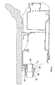
- a dirt collection receptacle 16 is removably attached to the housing 4 by means of a suitable latching mechanism (not shown) and defines a dirt collection chamber 18.
- the receptacle 16 has a central raised portion 20 for sealing engagement with a cylindrical filter element 22 formed from pleated fibrous material, such as paper or textile, covered by a breathable fabric, and is closed by a lid 24 which sealingly engages upper part 26 of filter element 22 by means of an annular seal 28, the annular seal surrounding a vent 30 in the lid 24, the function of which will be described in greater detail below.
- the lid 24 also has an edge 32 for gripping by a user during lifting of the lid.
- the dirt collection unit 16 is held in position by the latching mechanism against an inner wall 34 of a recess integrally formed with the main part 5 of the housing 4.
- the raised portion 20 of the dirt collection unit 16 has a central aperture 36 cooperating with an aperture in upper wall 34 of recess 36, the raised portion 20 being surrounded by first 40 and second 42 trough regions for collecting dirt, in a manner which will be described in greater detail below.
- a motor chamber 44 communicates with recess 36 via an aperture 46, and a motor 48 is mounted via sealing mounts 50 for rotation about an axis 52.
- a fan (not shown) is mounted coaxially with motor 48 and communicates via exhaust outlet 54 with the atmosphere.
- a filter cassette (not shown) containing a hepa filter is mounted in outlet 54 for filtering air expelled out of the outlet 54 by means of the fan.
- the recess 36 is closed by means of closure plate 56, which is mounted to the main housing part 4, and is provided with a bypass valve 58 for allowing entry of air into recess 36 if the air pressure within recess 36 falls below a predetermined value.
- closure plate 56 which is mounted to the main housing part 4, and is provided with a bypass valve 58 for allowing entry of air into recess 36 if the air pressure within recess 36 falls below a predetermined value.
- the main housing part 4 can be easily injection moulded, the inner wall 34 forming a recessed part of the main housing part 4.
- the recess 36 is then closed by means of closure plate 56 so that the recess 36 defines a duct between the outlet 38 of filter unit 22 and an inlet of the motor chamber 44.
- Actuation of motor 46 by means of ON/OFF switch 10 causes the fan to radially displace air out of outlets 54 in the direction of arrow A shown in Figure 3.
- suction is caused upstream of the fan, which draws air from recess 36 generally axially into motor chamber 44 in the direction of arrow B.
- This causes dirty air to be drawn through inlet 12 (to which a suitable accessory such as a floor cleaning head ( Figure 5) is connected by means of a flexible hose ( Figure 12)), and is drawn into dirt collection chamber 18 in the direction of arrow C and then inwardly through the walls of filter unit 22 in the direction of arrows D and E.
- annular seal 28 surrounding vent 30 the only source of air to the motor chamber 44 at negative pressure is via inlet 12.
- the air filtered by filter unit 22 then passes out of aperture 38 and along the duct defined by recess 36 in the direction of arrow F. If the inlet 12 should become blocked (for example as a result of an obstacle coming into contact with it) the resulting pressure difference between the interior of recess 36 and the atmosphere causes bypass valve 58 to allow air to enter the recess 36 to prevent motor 46 from overheating.
- the air path from the inlet 12 to the outlet 38 via the filter unit 22 is shown in more detail in Figure 8.
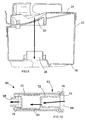
- a "filter full" indicator mechanism 60 is mounted to closure plate 56 in recess 36 at a part of the closure plate having a transparent window portion 62.
- the indicator mechanism 60 comprises a housing 64 having an opening 66 into which air enters from externally of the vacuum cleaner housing 4 by means of a suitable valve, which may be the by-pass valve shown in Figure 3.
- the housing 64 has an outlet 68 open to the interior of recess 36, and is provided with a green perforated cover member 70 which can slide axially relative to a red perforated flag member 72, which has a flange 74 abutting a corresponding recess 76 in the housing 64.
- a cover member 70 is urged over the flag member 72 by means of a compression spring 78.
- the user lifts lid 24 by means of gripping portion 32, and then removes filter unit 22 and dirt collection chamber 16. Because the central portion of the dirt collection chamber 16 is raised, dirt trapped on the outer surface of filter unit 22 has a tendency to fall into trough regions 40, 42 and avoids falling into outlet 38. If the motor 46 should accidentally be actuated when the filter unit 22 is removed, the opening provided by opened lid 24 is nearer to outlet 38 than inlet 12, as a result of which relatively clean air from the atmosphere passes into recess 36 in preference to dirty air from the inlet 12, thus minimising the risk of the motor 46 being damaged by dirt.
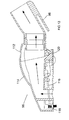
- the flexible hose 14 is connected to housing inlet 12 by means of a hose connection moulding 80 having a radially inner part 82 which cooperates with a rubber seal 84 (which also forms a seal with dirt collection chamber 16) and a radially outer part 86 which is provided with resilient fingers 88 having heads 90, which locate behind edge portions 92 of the main housing part 4 to hold the connector 80 in position.
- the resilient fingers 88 are pushed radially inwards until the heads 90 are released from the corresponding edge parts 92, so that the connector 80 can be axially withdrawn from the inlet 12.
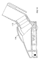
- Figures 11 and 12 show a rigid tube 94 carrying a floor cleaning head 96 removably mounted to the housing 4 for storage by locating an elongate projection 98 provided on cleaning head 96 in a corresponding recess 100 on housing 4.
- a collar 102 surrounding tube 94 has a latching portion 104 and an inclined surface 106, and cooperates with a spring loaded latching portion 108 on housing 4 having corresponding inclined surface 110.
- Movement of the upper part of the tube 94 shown in Figure 11 in the direction of arrow G causes mutual engagement of latching portion 104 and inclined surface 110, as a result of which latching portion 108 is displaced against the action of a spring (not shown) to cause latching portion 104 to be latched in position behind latching member 108 with inclined surfaces 106, 110 in contact with each other.
- a release catch (not shown) is depressed to displace latching member 108 against the action of the spring so that the latching portion 104 of collar 102 can be withdrawn from the housing.
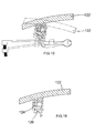
- Figure 19 shows a further embodiment of collar 202 for mounting to the rigid tube 94 and mounting the rigid tube 94 to the housing 4.
- Parts common to the embodiment of Figures 11 and 12 are denoted by like reference numerals but increased by 100.
- the collar 202 is formed as two separate parts, a first part 240 formed as an injection moulded split ring and a tubular second part 242 which is removably attachable to the first part 240.
- the first part 240 has a tubular section 244 which is placed around the tube 94 and is formed on one side with latching portion 204 having inclined surface 206.
- the latching portion is formed as a hollow component to enable the first part 240 to be injection moulded while having sufficient strength.
- the first part 240 is also provided with a generally rectangular projection 246 divided by a groove 248 at the split part of tubular section 244, the projection 246 being arranged opposite the latching portion 204.
- the second part 242 has an annular collar 250 having a slot 252 having an open end 254 and a closed end (not shown) for receiving the rectangular projection 246 on first part 240.
- the collar 250 surrounds a tubular body portion 256 having open ends for receiving an accessory 258, 260 at each end in an interference fit.
- the slot 252 can be mounted to the projection 246 from either direction, thus permitting left and right handed use of the collar 202, and the second part 242 is correctly located on the first part 240 by means of the closed end (not shown) of slot 252 and engagement of a projection (not shown) in slot 252 with groove 248 in projection 246.
- the orientation of the slot 252 relative to the body portion 256 is such that the body portion 256 and the accessories 258, 260 extend generally parallel to the longitudinal axis of tube 94. In this way, space can be particularly efficiently used for storing accessories 258, 260 on tube 94. Furthermore, by providing a collar 202 which serves the dual functions of mounting accessories 258, 260 to tube 94, and mounting tube 94 to the housing by means of latching portion 204, only a single component need by constructed, which reduces the cost of manufacturing the vacuum cleaner incorporating collar 202.
- Figures 13 to 18 show in more detail the floor cleaning head 96 shown in Figure 11.
- the cleaning head 96 has a connector portion 112 pivotally mounted to a head portion 114, so that the angle of the connector portion 112 relative to the head portion 114 can be adjusted, as shown in Figures 13 and 14.
- a brush plate 116 carries a brush member 118 and is connected to a pivot 120 located at the rear of the head portion 114.
- the position of the brush member 118 relative to the head portion 114 is adjusted by means of a lever 122 ( Figures 15 to 18) carrying actuator member 124 which pivots about axis 126 to move a projection 128 on actuator member 124 along an inclined surface 130 of brush plate 116.
- This causes pivotal movement of brush plate 116 about pivot 120 to move the brush member 118 between “brush up” and “brush down” positions.
- the brush plate 116 is urged into the "brush up” and “brush down” positions by means of suitable springs (not shown).
- the body portion 256 of Figure 19 may extend generally at right angles to the longitudinal axis of tube 94.
Applications Claiming Priority (2)
| Application Number | Priority Date | Filing Date | Title |
|---|---|---|---|
| GB0314945 | 2003-06-26 | ||
| GBGB0314945.7A GB0314945D0 (en) | 2003-06-26 | 2003-06-26 | Vacuum cleaner |
Publications (3)
| Publication Number | Publication Date |
|---|---|
| EP1493374A2 true EP1493374A2 (fr) | 2005-01-05 |
| EP1493374A3 EP1493374A3 (fr) | 2005-11-23 |
| EP1493374B1 EP1493374B1 (fr) | 2008-12-10 |
Family
ID=27637420
Family Applications (1)
| Application Number | Title | Priority Date | Filing Date |
|---|---|---|---|
| EP04014041A Not-in-force EP1493374B1 (fr) | 2003-06-26 | 2004-06-16 | Aspirateur comportant des moyens pour la protection du moteur |
Country Status (7)
| Country | Link |
|---|---|
| US (1) | US8141200B2 (fr) |
| EP (1) | EP1493374B1 (fr) |
| AT (1) | ATE416663T1 (fr) |
| AU (1) | AU2004202724B2 (fr) |
| DE (1) | DE602004018233D1 (fr) |
| GB (1) | GB0314945D0 (fr) |
| NZ (1) | NZ533717A (fr) |
Cited By (1)
| Publication number | Priority date | Publication date | Assignee | Title |
|---|---|---|---|---|
| EP1955631A1 (fr) * | 2007-02-12 | 2008-08-13 | Black & Decker, Inc. | Aspirateurs |
Families Citing this family (4)
| Publication number | Priority date | Publication date | Assignee | Title |
|---|---|---|---|---|
| JP4770821B2 (ja) * | 2007-11-16 | 2011-09-14 | パナソニック株式会社 | 電気掃除機 |
| US9101252B2 (en) | 2011-03-03 | 2015-08-11 | G.B.D. Corp. | Configuration of a surface cleaning apparatus |
| US8973212B2 (en) * | 2011-03-03 | 2015-03-10 | G.B.D. Corp. | Filter housing construction for a surface cleaning apparatus |
| US8973214B2 (en) | 2011-03-03 | 2015-03-10 | G.B.D. Corp. | Cyclone chamber and dirt collection assembly for a surface cleaning apparatus |
Citations (10)
| Publication number | Priority date | Publication date | Assignee | Title |
|---|---|---|---|---|
| NL42636C (fr) * | 1900-01-01 | |||
| US2771151A (en) * | 1953-08-11 | 1956-11-20 | Ralph C Osborn | Vacuum cleaner |
| DE1945313A1 (de) * | 1969-09-06 | 1971-03-11 | Siemens Elektrogeraete Gmbh | Staubsauger |
| US5829090A (en) * | 1996-01-11 | 1998-11-03 | Black & Decker Inc. | Vacuum cleaner with combined filter element and collection unit |
| US6256834B1 (en) * | 1998-12-17 | 2001-07-10 | U.S. Philips Corporation | Vacuum cleaner with detachable dust container |
| US6342084B1 (en) * | 1997-07-31 | 2002-01-29 | Fantovac Industries Pty Ltd | Vacuum cleaner |
| DE10129596A1 (de) * | 2000-07-21 | 2002-01-31 | Vorwerk Co Interholding | Staubsauger |
| EP1179312A2 (fr) * | 2000-08-07 | 2002-02-13 | Hoover Limited | Aspirateur de poussières |
| GB2372431A (en) * | 2001-02-24 | 2002-08-28 | Dyson Ltd | Air bleed valve arrangement in a vacuum cleaner |
| US20020120998A1 (en) * | 2000-05-16 | 2002-09-05 | Roland Dubos | Waste collecting container for vacum cleaner |
Family Cites Families (17)
| Publication number | Priority date | Publication date | Assignee | Title |
|---|---|---|---|---|
| US2539195A (en) * | 1950-05-02 | 1951-01-23 | Gen Electric | Inlet dirt deflector and filter arrangement for suction cleaners |
| US4179768A (en) * | 1977-03-16 | 1979-12-25 | Aktiebolaget Electrolux | Vacuum dumping arrangement for a wet/dry vacuum cleaner |
| GB2137896B (en) | 1983-04-12 | 1987-05-20 | Hoover Plc | Suction cleaner |
| US4527302A (en) * | 1983-11-21 | 1985-07-09 | The Hoover Company | Canister cleaner |
| KR870001812A (ko) * | 1985-08-08 | 1987-03-28 | 이노우에 가오루 | 소형 휴대용 전기 소제기 |
| CA2160289C (fr) * | 1994-10-31 | 1999-09-28 | Yutaka Tomooka | Un aspirateur electrique |
| EP0881218B1 (fr) * | 1995-12-27 | 2003-10-22 | Mitsubishi Pharma Corporation | Composes de prevention/traitement s'appliquant aux complications de diabetes |
| GB9624982D0 (en) * | 1996-11-30 | 1997-01-15 | Black & Decker Inc | Hand-held vacuum cleaner |
| US5946771A (en) * | 1997-01-09 | 1999-09-07 | The Hoover Company | Vacuum cleaner air exhaust arrangement |
| US5820090A (en) * | 1997-04-02 | 1998-10-13 | Nickels; William A. | Paint laden paint brush holder |
| GB0019194D0 (en) | 2000-08-07 | 2000-09-27 | Hoover Ltd | Vacuum cleaner |
| US6436160B1 (en) * | 2001-01-11 | 2002-08-20 | Royal Appliance Mfg. Co. | Dirt cup assembly for vacuum cleaner |
| GB2373431A (en) | 2001-03-22 | 2002-09-25 | Jonathan Paul Tye | Jewellery protector |
| GB2374524B (en) | 2001-04-17 | 2004-08-04 | Hoover Ltd | Vacuum cleaner |
| GB2377165B (en) * | 2001-07-06 | 2004-06-30 | Black & Decker Inc | Locking mechanism for dust collection module of vacuum cleaner |
| KR100433408B1 (ko) | 2002-03-05 | 2004-05-31 | 삼성광주전자 주식회사 | 진공청소기 |
| EP1413238B1 (fr) * | 2002-10-23 | 2009-09-02 | Panasonic Corporation | Aspirateur |
-
2003
- 2003-06-26 GB GBGB0314945.7A patent/GB0314945D0/en not_active Ceased
-
2004
- 2004-06-16 EP EP04014041A patent/EP1493374B1/fr not_active Not-in-force
- 2004-06-16 DE DE602004018233T patent/DE602004018233D1/de active Active
- 2004-06-16 AT AT04014041T patent/ATE416663T1/de not_active IP Right Cessation
- 2004-06-21 AU AU2004202724A patent/AU2004202724B2/en not_active Ceased
- 2004-06-23 NZ NZ533717A patent/NZ533717A/en unknown
- 2004-06-25 US US10/876,806 patent/US8141200B2/en not_active Expired - Fee Related
Patent Citations (10)
| Publication number | Priority date | Publication date | Assignee | Title |
|---|---|---|---|---|
| NL42636C (fr) * | 1900-01-01 | |||
| US2771151A (en) * | 1953-08-11 | 1956-11-20 | Ralph C Osborn | Vacuum cleaner |
| DE1945313A1 (de) * | 1969-09-06 | 1971-03-11 | Siemens Elektrogeraete Gmbh | Staubsauger |
| US5829090A (en) * | 1996-01-11 | 1998-11-03 | Black & Decker Inc. | Vacuum cleaner with combined filter element and collection unit |
| US6342084B1 (en) * | 1997-07-31 | 2002-01-29 | Fantovac Industries Pty Ltd | Vacuum cleaner |
| US6256834B1 (en) * | 1998-12-17 | 2001-07-10 | U.S. Philips Corporation | Vacuum cleaner with detachable dust container |
| US20020120998A1 (en) * | 2000-05-16 | 2002-09-05 | Roland Dubos | Waste collecting container for vacum cleaner |
| DE10129596A1 (de) * | 2000-07-21 | 2002-01-31 | Vorwerk Co Interholding | Staubsauger |
| EP1179312A2 (fr) * | 2000-08-07 | 2002-02-13 | Hoover Limited | Aspirateur de poussières |
| GB2372431A (en) * | 2001-02-24 | 2002-08-28 | Dyson Ltd | Air bleed valve arrangement in a vacuum cleaner |
Cited By (4)
| Publication number | Priority date | Publication date | Assignee | Title |
|---|---|---|---|---|
| EP1955631A1 (fr) * | 2007-02-12 | 2008-08-13 | Black & Decker, Inc. | Aspirateurs |
| US8028373B2 (en) | 2007-02-12 | 2011-10-04 | Black & Decker Inc. | Vacuum cleaners |
| AU2008200579B2 (en) * | 2007-02-12 | 2011-10-06 | Black & Decker Inc | Vacuum cleaners |
| US8918952B2 (en) | 2007-02-12 | 2014-12-30 | Black & Decker Inc. | Vacuum cleaner |
Also Published As
| Publication number | Publication date |
|---|---|
| DE602004018233D1 (de) | 2009-01-22 |
| ATE416663T1 (de) | 2008-12-15 |
| EP1493374A3 (fr) | 2005-11-23 |
| US8141200B2 (en) | 2012-03-27 |
| AU2004202724B2 (en) | 2010-08-12 |
| GB0314945D0 (en) | 2003-07-30 |
| AU2004202724A1 (en) | 2005-01-20 |
| NZ533717A (en) | 2005-12-23 |
| EP1493374B1 (fr) | 2008-12-10 |
| US20050011039A1 (en) | 2005-01-20 |
Similar Documents
| Publication | Publication Date | Title |
|---|---|---|
| US7517377B2 (en) | Dust collecting unit for use in cleaner | |
| RU2277372C2 (ru) | Пылесборник робота-пылесоса | |
| US7669282B2 (en) | Vacuum cleaner | |
| CN212698706U (zh) | 清洁装置和清洁设备 | |
| US7581286B2 (en) | Vacuum cleaner and dust collection unit thereof | |
| AU2007200171B2 (en) | Vacuum cleaner filter cleaning mechanisms | |
| US20100306955A1 (en) | Filter Cleaning System for a Vacuum Cleaner | |
| US20230092045A1 (en) | Cleaner | |
| US8347453B2 (en) | Vacuum cleaner bag docking assembly | |
| US7462210B2 (en) | Dust collecting unit for vacuum cleaner | |
| EP1493374B1 (fr) | Aspirateur comportant des moyens pour la protection du moteur | |
| US7478456B2 (en) | Mounting device for vacuum cleaner accessory | |
| US11426044B1 (en) | Cleaning device | |
| US7383606B2 (en) | Vacuum cleaner | |
| KR100857491B1 (ko) | 집진 용기 및 전기 청소기 | |
| KR0133761B1 (ko) | 습식 및 건식(Wet and dry type) 진공청소기 | |
| KR20220140315A (ko) | 청소기 |
Legal Events
| Date | Code | Title | Description |
|---|---|---|---|
| PUAI | Public reference made under article 153(3) epc to a published international application that has entered the european phase |
Free format text: ORIGINAL CODE: 0009012 |
|
| AK | Designated contracting states |
Kind code of ref document: A2 Designated state(s): AT BE BG CH CY CZ DE DK EE ES FI FR GB GR HU IE IT LI LU MC NL PL PT RO SE SI SK TR |
|
| AX | Request for extension of the european patent |
Extension state: AL HR LT LV MK |
|
| PUAL | Search report despatched |
Free format text: ORIGINAL CODE: 0009013 |
|
| AK | Designated contracting states |
Kind code of ref document: A3 Designated state(s): AT BE BG CH CY CZ DE DK EE ES FI FR GB GR HU IE IT LI LU MC NL PL PT RO SE SI SK TR |
|
| AX | Request for extension of the european patent |
Extension state: AL HR LT LV MK |
|
| RIC1 | Information provided on ipc code assigned before grant |
Ipc: 7A 47L 5/36 B Ipc: 7A 47L 9/00 B Ipc: 7A 47L 9/19 A Ipc: 7A 47L 9/14 B |
|
| 17P | Request for examination filed |
Effective date: 20051206 |
|
| AKX | Designation fees paid |
Designated state(s): AT BE BG CH CY CZ DE DK EE ES FI FR GB GR HU IE IT LI LU MC NL PL PT RO SE SI SK TR |
|
| 17Q | First examination report despatched |
Effective date: 20070330 |
|
| GRAP | Despatch of communication of intention to grant a patent |
Free format text: ORIGINAL CODE: EPIDOSNIGR1 |
|
| GRAS | Grant fee paid |
Free format text: ORIGINAL CODE: EPIDOSNIGR3 |
|
| GRAS | Grant fee paid |
Free format text: ORIGINAL CODE: EPIDOSNIGR3 |
|
| GRAA | (expected) grant |
Free format text: ORIGINAL CODE: 0009210 |
|
| AK | Designated contracting states |
Kind code of ref document: B1 Designated state(s): AT BE BG CH CY CZ DE DK EE ES FI FR GB GR HU IE IT LI LU MC NL PL PT RO SE SI SK TR |
|
| REG | Reference to a national code |
Ref country code: GB Ref legal event code: FG4D |
|
| REG | Reference to a national code |
Ref country code: CH Ref legal event code: EP |
|
| REG | Reference to a national code |
Ref country code: IE Ref legal event code: FG4D |
|
| REF | Corresponds to: |
Ref document number: 602004018233 Country of ref document: DE Date of ref document: 20090122 Kind code of ref document: P |
|
| PG25 | Lapsed in a contracting state [announced via postgrant information from national office to epo] |
Ref country code: SI Free format text: LAPSE BECAUSE OF FAILURE TO SUBMIT A TRANSLATION OF THE DESCRIPTION OR TO PAY THE FEE WITHIN THE PRESCRIBED TIME-LIMIT Effective date: 20081210 Ref country code: PL Free format text: LAPSE BECAUSE OF FAILURE TO SUBMIT A TRANSLATION OF THE DESCRIPTION OR TO PAY THE FEE WITHIN THE PRESCRIBED TIME-LIMIT Effective date: 20081210 Ref country code: FI Free format text: LAPSE BECAUSE OF FAILURE TO SUBMIT A TRANSLATION OF THE DESCRIPTION OR TO PAY THE FEE WITHIN THE PRESCRIBED TIME-LIMIT Effective date: 20081210 |
|
| PG25 | Lapsed in a contracting state [announced via postgrant information from national office to epo] |
Ref country code: BG Free format text: LAPSE BECAUSE OF FAILURE TO SUBMIT A TRANSLATION OF THE DESCRIPTION OR TO PAY THE FEE WITHIN THE PRESCRIBED TIME-LIMIT Effective date: 20090310 Ref country code: ES Free format text: LAPSE BECAUSE OF FAILURE TO SUBMIT A TRANSLATION OF THE DESCRIPTION OR TO PAY THE FEE WITHIN THE PRESCRIBED TIME-LIMIT Effective date: 20090321 Ref country code: BE Free format text: LAPSE BECAUSE OF FAILURE TO SUBMIT A TRANSLATION OF THE DESCRIPTION OR TO PAY THE FEE WITHIN THE PRESCRIBED TIME-LIMIT Effective date: 20081210 Ref country code: EE Free format text: LAPSE BECAUSE OF FAILURE TO SUBMIT A TRANSLATION OF THE DESCRIPTION OR TO PAY THE FEE WITHIN THE PRESCRIBED TIME-LIMIT Effective date: 20081210 Ref country code: RO Free format text: LAPSE BECAUSE OF FAILURE TO SUBMIT A TRANSLATION OF THE DESCRIPTION OR TO PAY THE FEE WITHIN THE PRESCRIBED TIME-LIMIT Effective date: 20081210 |
|
| PG25 | Lapsed in a contracting state [announced via postgrant information from national office to epo] |
Ref country code: PT Free format text: LAPSE BECAUSE OF FAILURE TO SUBMIT A TRANSLATION OF THE DESCRIPTION OR TO PAY THE FEE WITHIN THE PRESCRIBED TIME-LIMIT Effective date: 20090511 Ref country code: CZ Free format text: LAPSE BECAUSE OF FAILURE TO SUBMIT A TRANSLATION OF THE DESCRIPTION OR TO PAY THE FEE WITHIN THE PRESCRIBED TIME-LIMIT Effective date: 20081210 Ref country code: SE Free format text: LAPSE BECAUSE OF FAILURE TO SUBMIT A TRANSLATION OF THE DESCRIPTION OR TO PAY THE FEE WITHIN THE PRESCRIBED TIME-LIMIT Effective date: 20090310 Ref country code: AT Free format text: LAPSE BECAUSE OF FAILURE TO SUBMIT A TRANSLATION OF THE DESCRIPTION OR TO PAY THE FEE WITHIN THE PRESCRIBED TIME-LIMIT Effective date: 20081210 |
|
| PG25 | Lapsed in a contracting state [announced via postgrant information from national office to epo] |
Ref country code: SK Free format text: LAPSE BECAUSE OF FAILURE TO SUBMIT A TRANSLATION OF THE DESCRIPTION OR TO PAY THE FEE WITHIN THE PRESCRIBED TIME-LIMIT Effective date: 20081210 |
|
| PLBE | No opposition filed within time limit |
Free format text: ORIGINAL CODE: 0009261 |
|
| STAA | Information on the status of an ep patent application or granted ep patent |
Free format text: STATUS: NO OPPOSITION FILED WITHIN TIME LIMIT |
|
| PG25 | Lapsed in a contracting state [announced via postgrant information from national office to epo] |
Ref country code: DK Free format text: LAPSE BECAUSE OF FAILURE TO SUBMIT A TRANSLATION OF THE DESCRIPTION OR TO PAY THE FEE WITHIN THE PRESCRIBED TIME-LIMIT Effective date: 20081210 |
|
| 26N | No opposition filed |
Effective date: 20090911 |
|
| PG25 | Lapsed in a contracting state [announced via postgrant information from national office to epo] |
Ref country code: MC Free format text: LAPSE BECAUSE OF NON-PAYMENT OF DUE FEES Effective date: 20090630 |
|
| REG | Reference to a national code |
Ref country code: CH Ref legal event code: PL |
|
| REG | Reference to a national code |
Ref country code: IE Ref legal event code: MM4A |
|
| PG25 | Lapsed in a contracting state [announced via postgrant information from national office to epo] |
Ref country code: IE Free format text: LAPSE BECAUSE OF NON-PAYMENT OF DUE FEES Effective date: 20090616 Ref country code: LI Free format text: LAPSE BECAUSE OF NON-PAYMENT OF DUE FEES Effective date: 20090630 Ref country code: CH Free format text: LAPSE BECAUSE OF NON-PAYMENT OF DUE FEES Effective date: 20090630 |
|
| PG25 | Lapsed in a contracting state [announced via postgrant information from national office to epo] |
Ref country code: GR Free format text: LAPSE BECAUSE OF FAILURE TO SUBMIT A TRANSLATION OF THE DESCRIPTION OR TO PAY THE FEE WITHIN THE PRESCRIBED TIME-LIMIT Effective date: 20090311 |
|
| PG25 | Lapsed in a contracting state [announced via postgrant information from national office to epo] |
Ref country code: LU Free format text: LAPSE BECAUSE OF NON-PAYMENT OF DUE FEES Effective date: 20090616 |
|
| PG25 | Lapsed in a contracting state [announced via postgrant information from national office to epo] |
Ref country code: HU Free format text: LAPSE BECAUSE OF FAILURE TO SUBMIT A TRANSLATION OF THE DESCRIPTION OR TO PAY THE FEE WITHIN THE PRESCRIBED TIME-LIMIT Effective date: 20090611 |
|
| PG25 | Lapsed in a contracting state [announced via postgrant information from national office to epo] |
Ref country code: TR Free format text: LAPSE BECAUSE OF FAILURE TO SUBMIT A TRANSLATION OF THE DESCRIPTION OR TO PAY THE FEE WITHIN THE PRESCRIBED TIME-LIMIT Effective date: 20081210 |
|
| PG25 | Lapsed in a contracting state [announced via postgrant information from national office to epo] |
Ref country code: CY Free format text: LAPSE BECAUSE OF FAILURE TO SUBMIT A TRANSLATION OF THE DESCRIPTION OR TO PAY THE FEE WITHIN THE PRESCRIBED TIME-LIMIT Effective date: 20081210 |
|
| REG | Reference to a national code |
Ref country code: FR Ref legal event code: PLFP Year of fee payment: 13 |
|
| REG | Reference to a national code |
Ref country code: FR Ref legal event code: PLFP Year of fee payment: 14 |
|
| PGFP | Annual fee paid to national office [announced via postgrant information from national office to epo] |
Ref country code: GB Payment date: 20170614 Year of fee payment: 14 Ref country code: FR Payment date: 20170511 Year of fee payment: 14 Ref country code: DE Payment date: 20170613 Year of fee payment: 14 |
|
| PGFP | Annual fee paid to national office [announced via postgrant information from national office to epo] |
Ref country code: IT Payment date: 20170619 Year of fee payment: 14 Ref country code: NL Payment date: 20170614 Year of fee payment: 14 |
|
| REG | Reference to a national code |
Ref country code: DE Ref legal event code: R119 Ref document number: 602004018233 Country of ref document: DE |
|
| REG | Reference to a national code |
Ref country code: NL Ref legal event code: MM Effective date: 20180701 |
|
| GBPC | Gb: european patent ceased through non-payment of renewal fee |
Effective date: 20180616 |
|
| PG25 | Lapsed in a contracting state [announced via postgrant information from national office to epo] |
Ref country code: NL Free format text: LAPSE BECAUSE OF NON-PAYMENT OF DUE FEES Effective date: 20180701 |
|
| PG25 | Lapsed in a contracting state [announced via postgrant information from national office to epo] |
Ref country code: DE Free format text: LAPSE BECAUSE OF NON-PAYMENT OF DUE FEES Effective date: 20190101 Ref country code: GB Free format text: LAPSE BECAUSE OF NON-PAYMENT OF DUE FEES Effective date: 20180616 Ref country code: FR Free format text: LAPSE BECAUSE OF NON-PAYMENT OF DUE FEES Effective date: 20180630 Ref country code: IT Free format text: LAPSE BECAUSE OF NON-PAYMENT OF DUE FEES Effective date: 20180616 |