EP1493339B1 - Rotary printing unit for a machine of the tobacco processing industry - Google Patents
Rotary printing unit for a machine of the tobacco processing industry Download PDFInfo
- Publication number
- EP1493339B1 EP1493339B1 EP04013074A EP04013074A EP1493339B1 EP 1493339 B1 EP1493339 B1 EP 1493339B1 EP 04013074 A EP04013074 A EP 04013074A EP 04013074 A EP04013074 A EP 04013074A EP 1493339 B1 EP1493339 B1 EP 1493339B1
- Authority
- EP
- European Patent Office
- Prior art keywords
- article
- printing
- printing element
- conveying direction
- printed
- Prior art date
- Legal status (The legal status is an assumption and is not a legal conclusion. Google has not performed a legal analysis and makes no representation as to the accuracy of the status listed.)
- Expired - Lifetime
Links
- 241000208125 Nicotiana Species 0.000 title claims description 45
- 235000002637 Nicotiana tabacum Nutrition 0.000 title claims description 45
- 235000019504 cigarettes Nutrition 0.000 claims description 58
- 238000000034 method Methods 0.000 claims description 24
- 239000000463 material Substances 0.000 description 31
- 230000032258 transport Effects 0.000 description 27
- 230000008569 process Effects 0.000 description 11
- 230000000391 smoking effect Effects 0.000 description 8
- 230000008859 change Effects 0.000 description 5
- 238000004519 manufacturing process Methods 0.000 description 4
- 238000005520 cutting process Methods 0.000 description 3
- 239000004744 fabric Substances 0.000 description 3
- 239000000758 substrate Substances 0.000 description 3
- 230000001360 synchronised effect Effects 0.000 description 3
- 239000002245 particle Substances 0.000 description 2
- 238000003892 spreading Methods 0.000 description 2
- 230000007480 spreading Effects 0.000 description 2
- 230000007704 transition Effects 0.000 description 2
- 238000004026 adhesive bonding Methods 0.000 description 1
- 230000008901 benefit Effects 0.000 description 1
- 235000019506 cigar Nutrition 0.000 description 1
- 230000001419 dependent effect Effects 0.000 description 1
- 238000009826 distribution Methods 0.000 description 1
- 239000012528 membrane Substances 0.000 description 1
- 238000003825 pressing Methods 0.000 description 1
- 238000000275 quality assurance Methods 0.000 description 1
- 230000001105 regulatory effect Effects 0.000 description 1
- 238000003860 storage Methods 0.000 description 1
Images


Classifications
-
- B—PERFORMING OPERATIONS; TRANSPORTING
- B41—PRINTING; LINING MACHINES; TYPEWRITERS; STAMPS
- B41F—PRINTING MACHINES OR PRESSES
- B41F17/00—Printing apparatus or machines of special types or for particular purposes, not otherwise provided for
- B41F17/08—Printing apparatus or machines of special types or for particular purposes, not otherwise provided for for printing on filamentary or elongated articles, or on articles with cylindrical surfaces
- B41F17/14—Printing apparatus or machines of special types or for particular purposes, not otherwise provided for for printing on filamentary or elongated articles, or on articles with cylindrical surfaces on articles of finite length
- B41F17/20—Printing apparatus or machines of special types or for particular purposes, not otherwise provided for for printing on filamentary or elongated articles, or on articles with cylindrical surfaces on articles of finite length on articles of uniform cross-section, e.g. pencils, rulers, resistors
-
- A—HUMAN NECESSITIES
- A24—TOBACCO; CIGARS; CIGARETTES; SIMULATED SMOKING DEVICES; SMOKERS' REQUISITES
- A24C—MACHINES FOR MAKING CIGARS OR CIGARETTES
- A24C5/00—Making cigarettes; Making tipping materials for, or attaching filters or mouthpieces to, cigars or cigarettes
- A24C5/38—Machines combined with printing devices
-
- B—PERFORMING OPERATIONS; TRANSPORTING
- B41—PRINTING; LINING MACHINES; TYPEWRITERS; STAMPS
- B41J—TYPEWRITERS; SELECTIVE PRINTING MECHANISMS, i.e. MECHANISMS PRINTING OTHERWISE THAN FROM A FORME; CORRECTION OF TYPOGRAPHICAL ERRORS
- B41J15/00—Devices or arrangements of selective printing mechanisms, e.g. ink-jet printers or thermal printers, specially adapted for supporting or handling copy material in continuous form, e.g. webs
- B41J15/04—Supporting, feeding, or guiding devices; Mountings for web rolls or spindles
-
- B—PERFORMING OPERATIONS; TRANSPORTING
- B41—PRINTING; LINING MACHINES; TYPEWRITERS; STAMPS
- B41J—TYPEWRITERS; SELECTIVE PRINTING MECHANISMS, i.e. MECHANISMS PRINTING OTHERWISE THAN FROM A FORME; CORRECTION OF TYPOGRAPHICAL ERRORS
- B41J15/00—Devices or arrangements of selective printing mechanisms, e.g. ink-jet printers or thermal printers, specially adapted for supporting or handling copy material in continuous form, e.g. webs
- B41J15/18—Multiple web-feeding apparatus
- B41J15/22—Multiple web-feeding apparatus for feeding webs in separate paths during printing
Definitions
- the invention relates to a method for applying printing marks on a transported along a transport direction with a predetermined conveying speed article of the tobacco processing industry, in particular wrapping strips, preferably cigarette paper strips, or a rod-shaped smoking article by means of a printing element, wherein along the transport direction during the printing process, the relative speed between the Pressure element and the article is reduced.
- the invention relates to a device for applying print marks on at least one article of the tobacco processing industry, preferably wrapping strips, in particular cigarette paper strips, or a rod-shaped smoking article, with a along a transport direction with a predetermined conveying speed promoted article and with a printing element, wherein the printing element during the printing operation along the transport direction of the article is movable so that the relative speed between the pressure element and the article is reduced.
- the invention relates to a machine of the tobacco processing industry, in particular cigarette rod or filter attachment machine.
- Prior art printing units for the application of print marks on a wrapping strip of the tobacco processing industry are known.
- an imprint on the cigarette paper strip is printed on cigarette paper strips in a cigarette rod machine with a pressure roller.
- rod-shaped articles such as cigarettes, cigarillos, cigars or filter rods or the like are produced in the strand process.
- the wrapping strip By means of the wrapping strip, the tobacco strands are wrapped in the cigarette rod machine, wherein the wrapping strips used have printed images, e.g. Cigarette brands, manufacturer names or other indications.
- the wrapping strip is printed, said appearing on the article imprint primarily the brand.
- Such a print or stamp is a conspicuous quality feature of such articles and requires special attention with regard to the components and production conditions required for its manufacture, such as the type and condition of the articles used Color and their supply, transfer and distribution through multiple rolls to the order through the wrapping strip.
- the printing units according to the prior art installed in the stranding machines consist of a roll arrangement, wherein the material web to be printed is guided between the rolls.
- a so-called pressure roller is provided, which is synchronized with the continuously moving material web.
- the pressure roller is in contact with a counter-pressure roller, wherein the enveloping strip is guided between the pressure roller and the counter-pressure roller.
- the printing units have the disadvantage that as a result of the rotation of the pressure roller at higher conveying speed of the wrapping strip, the quality of the imprint is reduced or may be impossible, so that the production of cigarette strands with a print on the wrapping strip is severely limited at higher machine speeds.
- DE-A-101 30 225 is a printing unit for the application of print marks on a wrapping strip of the tobacco-processing industry described.
- the printing unit has two rotating ones Pressure rollers and a counter-pressure roller, wherein the two pressure rollers are in contact with the counter-pressure roller and a web of material in the form of a cigarette paper strip is continuously guided between them.
- the print marks are applied by elevations or depressions of a pressure roller.
- a method and apparatus for printing using a printing device with a printhead includes a plurality of printing elements for transferring a pixel of a printing medium from a carrier to an adjacent substrate.
- relative movement between the substrate and the carrier and printhead is caused such that the printhead moves from a different position to a final print position relative to a surface of the carrier. Further, during the printing operation, the surface of the carrier and the substrate are moved at a same speed in a feeding direction.
- This object is achieved in a method for applying print marks on a along a transport direction with a predetermined conveying speed promoted article of the tobacco processing industry, in particular wrapping strips, preferably cigarette paper strips or a rod-shaped smoking article by means of a pressure element, wherein along the transport direction during the printing process, the relative speed between the printing element and the article is reduced, in that the printing element and / or the article are moved transversely, in particular perpendicular, to the transport direction, wherein the printing operation is transverse to the transport direction of the article.
- the printing image-generating printing element is (co-) moved in the transport direction of the conveyed article, so that during this co-movement of the printing element with the article takes place a secure printing of the print mark by the printing element.
- the material strip to be printed is no longer unrolled on the pressure roller, but the pressure element is also conveyed in the conveying direction of the material strip.
- a uniform imprint is achieved in particular when the printing element and / or the article are moved transversely, in particular vertically, to the transport direction, the printing element and the article moving in the same transport direction.
- two directions of movement, in and across the direction of conveyance, are superimposed. For example, if the pressure element is guided perpendicular to the transport direction, the pressure element simultaneously exerts a lifting movement.
- a secure imprint on the article is achieved by moving the printing element along the direction of transport at approximately the same or the same speed as the conveying speed of the article.
- the pressure element and / or the article perform a forward and a backward movement transversely, in particular vertically, to the transport direction.
- the pressure element is returned to its original position before the start of printing, so that the pressure element after a certain period of time or at equidistant intervals applies one or more printed image on the article.
- the article during the printing process in particular looped, deflected, so that this leads to a compact design of the printing device. Due to the loop-shaped deflection, a larger transport path is covered.
- the article is conveyed on a rotary body during the printing process, since the article with one side, i. unprinted side, rests on the rotating body and is printed from the other side.
- the pressing member is guided on a rotary body, so that the relative speed to the article is low when the article is conveyed on the rotary body of the article.
- a plurality of print marks are printed on the article by means of the printing element, so that in addition to a brand name, for example, product-identifying numbers are printed on surfaces of the wrapping strip, which are covered at later gluing processes, for example, from the covering paper leaflets on the filter attachment machine.
- imprints can be applied to these areas in the seam area of the cigarettes in order to be able to determine the authenticity of the product.
- the printing element is programmed with print data for the print mark or the print marks, so that a quick format change to the printing device without changing the printing element is possible.
- a corresponding data record for the new format must be transmitted to the printing element, so that the new print for the new tobacco format to be produced is applied to the wrapping strip.
- the printing element is replaced after consumption of consumable material of the printing element, so that a quick change, for example, an empty printer cartridge is performed quickly.
- the printing element is adjusted for the printing process, so that the printing element is easily adapted according to the requirements of the printed image and paper or other operating conditions for an impression.
- the object is further achieved by means of a device for applying print marks to at least one article of the tobacco processing industry, preferably wrapping strips, in particular cigarette paper strips, or a rod-shaped smoking article, with a conveyed along a transport direction with a predetermined conveying speed article and with a pressure element, wherein the pressure element is movable during the printing operation along the transport direction of the article such that the relative speed between the printing element and the article is reduced, which is further developed in that the printing element and / or the article transversely, in particular perpendicular, are movable to the transport direction, wherein the printing operation takes place transversely to the transport direction of the article.
- the pressure element along the transport direction at an approximately the same or the same speed as the conveying speed of the article is movable.
- the printing element and / or the article are transversely, in particular vertically, movable forward and backward to the transport direction.
- a space-saving printing device is achieved when a device for, in particular loop-shaped, deflection of the article is provided during the printing process.
- a rotary body is provided for conveying the article during the printing process.
- a plurality of printing elements are provided, so that several portions of, for example, a wrapping paper strip are provided simultaneously and side by side with a printed image during the promotion of the article.
- At least one pressure element is programmable, so that is changed in a format change on a cigarette rod machine, the imprint on the cigarette paper strip in a simple manner. This eliminates a costly change, for example, a pressure roller according to the prior art with a new typeface.
- the printing ink is consumed in the printing element, it is preferred if at least one printing element is exchangeable. The replacement can be done automatically.
- a preferred embodiment of the device is characterized in that at least one printing element applies a multicolored print mark to the article.
- the object is achieved by a machine of the tobacco processing industry, in particular cigarette rod machine or filter attachment machine, which is provided with a device according to the invention described above.
- the printing device according to the invention is preferably used on a cigarette rod machine for printing a wrapping strip.
- the printing device according to the invention it is also possible by the printing device according to the invention to print individual ready-made filter cigarettes or other rod-shaped smoking article.
- cigarette rod machine is fed from a lock 1 a pre-distributor 2 in portions with tobacco.
- a removal roller 3 of the pre-distributor 2 added controlled a reservoir 4 with tobacco, from which a steep conveyor 5 takes tobacco and fed a stowage 6 controlled.
- a pin roller 7 From the storage shaft 6 takes a pin roller 7 a uniform stream of tobacco, which is knocked out by a rollover roller 8 of the pins of the pin roller 7 and thrown on a circulating at a constant speed spreading cloth 9.
- a tobacco fleece formed on the spreading cloth 9 is thrown into a sighting device 11, which consists essentially of an air curtain, the larger or heavier tobacco particles happen, while all other tobacco particles from the air in a funnel formed by a pin roller 12 and a wall 13 14th be steered.
- the tobacco is thrown into a tobacco channel 16 against a rope conveyor 17, where the tobacco held by means sucked into a vacuum chamber 18 air and a tobacco rod is alsauert.
- An equalizer 19 removes excess tobacco from the tobacco rod, which is then placed on a run in synchronized cigarette paper strip 21.
- the cigarette paper strip 21 is withdrawn from a reel 22, passed through a printing device 23 and placed on a driven format tape 24.
- the format strip 24 transports the tobacco rod and the cigarette paper strip 21 through a format 26, in which the cigarette paper strip 21 is folded around the tobacco rod, so that still protrudes an edge which is glued in a known manner by a Glimapparat, not shown. Then the seam is closed and from a Tandemnahtplätte 27 dried.
- a thus formed cigarette rod 28 passes through a strand density meter 29, which controls the Egalizer 19, and is cut by a knife apparatus 31 in double-length cigarettes 32.
- the doppeliangen cigarettes 32 are transferred from a controlled arms 33 having transfer device 34 of a transfer drum 36 of a Filteransetzmaschine 37, on the cutting drum 38, they are divided with a circular blade in single cigarettes.
- Conveyor belts 39, 41 promote excess tobacco in a arranged from the reservoir 4 container 42, from which the recycled tobacco is removed from the vertical conveyor 5 again.
- printing device 230 two tracks of a material strip 210.1, 210.2 are provided with print marks for a double-strand machine. Of course it is possible to print on only one strip of material.
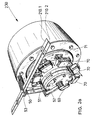
- FIGS. 2a to 2c perspectively different views of the printing device 230 are shown.
- the two strips of material 210.1, 210.2 are deflected parallel and side by side by means of two deflection rollers 50, 51, so that the material strips 210.1, 210.2 abut a rotating cylinder body 60 and wrap around the cylinder body 60 with a high degree of wrap.
- the deflection roller 51 is arranged on an arm 52, so that the strips of material 210.1, 210.2 are well tensioned and wrinkle-free on the lateral surface of the cylinder body 60.
- print heads 70 are arranged on a rotary body 71 at regular intervals.
- the rotating body 71 rotates in the same direction as the cylinder body 60.
- the printing heads 70 are moved perpendicular to the direction of rotation so that printing marks are printed on the material strips 210.1, 210.2 during their lifting movement.
- a full lifting movement of the print head 70 is carried out with a forward and backward movement. During this forward and backward movement, the print marks are completely printed on the strips of material 210.1, 210.2.
- the ink used in particular complies with state standards or tobacco regulations.
- the ink in the container of the ink cartridges in particular a regulated, pressure exerted, which counteracts the speed-dependent centrifugal forces. Between the atmosphere and the ink there is a membrane for this purpose.
- the rotational speed or the conveying speed of the printing heads 70 on the rotary body 71 and the material strips 210.1, 210.2 or the rotational speed of the cylinder body 60 are the same, so that there is no relative speed between the strips of material 210.1, 210.2 and the respective print heads 70. This ensures a secure printing of the print marks even at a high conveying speed of the material strips 210.1, 210.1.
- the two strips of material 210.1, 210.2 are each fed via a deflection roller 53 to a tobacco rod on a double-lane cigarette rod machine.
- the print marks are applied to the mouth-side end of the material strips 210.1, 210.2 of the later-formed tobacco sticks of simple length.
- the contiguous print marks are printed mirror-inverted at the later interface of a double-length tobacco stick.
- the print heads 70 have two application points arranged next to one another.
- FIGS. 3a, 3b are shown schematically in a front view and a side view of a printing device 23 for a one-lane material strip 21.
- the strip of material 21 via the pulleys 50, 51 and 53 with a high wrap around the lateral surface of the cylinder body 60 led around.
- the printing process is carried out transversely to the transport direction, with the simultaneous use of multiple print heads 70, the time for the application of the printed image extended to a corresponding number of cigarette cycles.
- the print heads are also possible to arrange the print heads within the cylinder body 60, so that the application of the print marks on the strips of material takes place from the inside. In this case, the stroke to be executed by the printheads is lower, since in this case only the printing area has to be covered and the paper circulates outside on the lateral surface of the cylinder body 60.
- Fig. 3a With Roman numerals, the various work areas of the print heads are shown during their rotation and stroke during a complete rotation.
- area I a print head is guided next to the material strip 21, so that there is no printing in this area.
- area II a forward movement is carried out perpendicular to the plane and the print head 70 is guided laterally to the strip of material.
- the print head has its end position and the reversal point for the total stroke H (see FIG. Fig. 3b ) reached.
- the printhead is moved back in area IV, wherein in this area IV also the cigarette paper 21 is printed.
- area V the printhead is retracted.
- FIGS. 4a, 4b a further printing device 23 according to the invention is shown in a front and side view, wherein by means of a holder 54, the rollers 51, 52 perform the deflection of the cigarette paper strip 21.
- Fig. 5 schematically a portion of a cigarette paper strip 21 is shown, whose length corresponds to the length of two tobacco sticks.
- the printable area is hatched.
- Dashed line 121 represents the position of the later cutting edge of the tobacco sticks.
- the print head 70 has a print width DB, the entire dashed area can be printed.
- the overlapping area of a tipping paper leaflet and a tobacco rod This area is designated by the reference numeral 122. Since the tipping paper leaflet is wrapped around this joint, the printed information on the cigarette or the manner of production, etc. is not visible. Further information about the authenticity or quality assurance may be provided near the tobacco rod seam by the printhead 70. This area is provided with the reference number 123.
- printing devices 230, 23 are used as printing elements print heads 70 transversely or perpendicular to the transport direction of the material strips 210.1, 210.2, 21 moves.
- articles of the tobacco processing industry for example rod-shaped Smoking articles, in particular filter cigarettes, are moved transversely to the transport direction.
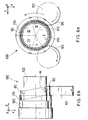
- An example is in the Figures 6a and 6b shown schematically in a front and side view.
- the drum assembly 100 shown in these figures is for example present in a filter attachment machine.
- filter cigarettes of simple use length 90 are transferred from a conveyor drum 101 to a conveyor drum 102.
- the filter cigarettes 90 are moved transaxially and perpendicular to the transport direction and inserted into the receptacles 170 of a printing drum 160. This takes place in area II.
- the printing drum 160 has individual print heads 170 whose number corresponds exactly to the number of recordings of the conveyor drum 102.
- the printing drum 160 moves at the same conveying speed as the conveying drum 102, so that there is no relative speed between the printing heads 170 and the inserted filter cigarettes 90.
- the advantage achieved by the invention is that on articles of the tobacco processing industry on a clean print image the article is applied, wherein the articles are conveyed at a high conveying speed, for example in a cigarette rod maker or a filter attachment machine.
- multicolored print images can be realized on the articles.
Landscapes
- Manufacturing Of Cigar And Cigarette Tobacco (AREA)
Description
Die Erfindung betrifft ein Verfahren zum Aufbringen von Druckmarken auf einen längs einer Transportrichtung mit einer vorbestimmten Fördergeschwindigkeit geförderten Artikel der tabakverarbeitenden Industrie, insbesondere Umhüllungsstreifen, vorzugsweise Zigarettenpapierstreifen, oder ein stabförmiger Rauchartikel, mittels eines Druckelements, wobei längs der Transportrichtung während des Druckvorgangs die Relativgeschwindigkeit zwischen dem Druckelement und dem Artikel verringert wird.The invention relates to a method for applying printing marks on a transported along a transport direction with a predetermined conveying speed article of the tobacco processing industry, in particular wrapping strips, preferably cigarette paper strips, or a rod-shaped smoking article by means of a printing element, wherein along the transport direction during the printing process, the relative speed between the Pressure element and the article is reduced.
Weiterhin betrifft die Erfindung eine Einrichtung zum Aufbringen von Druckmarken auf wenigstens einen Artikel der tabakverarbeitenden Industrie, vorzugsweise Umhüllungsstreifen, insbesondere Zigarettenpapierstreifen, oder ein stabförmiger Rauchartikel, mit einem längs einer Transportrichtung mit einer vorbestimmten Fördergeschwindigkeit geförderten Artikel und mit einem Druckelement, wobei das Druckelement während des Druckvorgangs längs der Transportrichtung des Artikels derart bewegbar ist, dass die Relativgeschwindigkeit zwischen dem Druckelement und dem Artikel verringert ist.Furthermore, the invention relates to a device for applying print marks on at least one article of the tobacco processing industry, preferably wrapping strips, in particular cigarette paper strips, or a rod-shaped smoking article, with a along a transport direction with a predetermined conveying speed promoted article and with a printing element, wherein the printing element during the printing operation along the transport direction of the article is movable so that the relative speed between the pressure element and the article is reduced.
Ferner betrifft die Erfindung eine Maschine der tabakverarbeitenden Industrie, insbesondere Zigarettenstrangmaschine oder Filteransetzmaschine.Furthermore, the invention relates to a machine of the tobacco processing industry, in particular cigarette rod or filter attachment machine.
Aus dem Stand der Technik sind Druckwerke für das Aufbringen von Druckmarken auf einem Umhüllungsstreifen der tabakverarbeitenden Industrie bekannt. Beispielsweise wird auf Zigarettenpapierstreifen in einer Zigarettenstrangmaschine mit einer Druckwalze ein Aufdruck auf den Zigarettenpapierstreifen aufgedruckt. In der Strangmaschine werden stabförmige Artikel wie Zigaretten, Zigarillos, Zigarren oder Filterstäbe oder dergleichen im Strangverfahren hergestellt. Mittels des Umhüllungsstreifens werden die Tabakstränge in der Zigarettenstrangmaschine umwickelt, wobei die verwendeten Umhüllungsstreifen Druckmarken bzw. Druckbilder aufweisen, die z.B. Zigarettenmarken, Herstellernamen oder sonstige Hinweise sein können.Prior art printing units for the application of print marks on a wrapping strip of the tobacco processing industry are known. For example, an imprint on the cigarette paper strip is printed on cigarette paper strips in a cigarette rod machine with a pressure roller. In the stranding machine rod-shaped articles such as cigarettes, cigarillos, cigars or filter rods or the like are produced in the strand process. By means of the wrapping strip, the tobacco strands are wrapped in the cigarette rod machine, wherein the wrapping strips used have printed images, e.g. Cigarette brands, manufacturer names or other indications.
Als Rauchartikel im erfindungsgemäßen Sinn sind Zigaretten mit und ohne Filter sowie alle andere stabförmigen Rauchartikel zu verstehen, deren Umhüllungsstreifen bedruckt ist, wobei der auf den Artikel erscheinende Aufdruck in erster Linie die Marke bezeichnet. Ein derartiger Aufdruck oder Stempel ist ein augenfälliges Qualitätsmerkmal derartiger Artikel und bedarf besonderer Aufmerksamkeit hinsichtlich der zu seiner Herstellung erforderlichen Komponenten und Produktionsbedingungen, wie Art und Zustand der verwendeten Farbe und deren Zuführung, Übertragung und Verteilung durch mehrere Walzen bis zum Auftrag durch den Hüllstreifen.As a smoking article in the context of the invention are understood cigarettes with and without filters and all other rod-shaped smoking articles, the wrapping strip is printed, said appearing on the article imprint primarily the brand. Such a print or stamp is a conspicuous quality feature of such articles and requires special attention with regard to the components and production conditions required for its manufacture, such as the type and condition of the articles used Color and their supply, transfer and distribution through multiple rolls to the order through the wrapping strip.
Die in den Strangmaschinen eingebauten Druckwerke gemäß dem Stand der Technik bestehen aus einer Walzenanordnung, wobei zwischen den Walzen die zu bedruckende Materialbahn geführt wird. Zum Aufbringen der Druckmarken bzw. Druckbilder ist eine sogenannte Druckwalze vorgesehen, die mit der kontinuierlich bewegten Materialbahn synchronisiert ist. In der Regel ist die Druckwalze dabei mit einer Gegendruckwalze in Kontakt, wobei der Umhüllungsstreifen zwischen der Druckwalze und der Gegendruckwalze geführt ist.The printing units according to the prior art installed in the stranding machines consist of a roll arrangement, wherein the material web to be printed is guided between the rolls. For applying the print marks or printed images, a so-called pressure roller is provided, which is synchronized with the continuously moving material web. In general, the pressure roller is in contact with a counter-pressure roller, wherein the enveloping strip is guided between the pressure roller and the counter-pressure roller.
Allerdings haben die Druckwerke den Nachteil, dass in Folge der Rotation der Druckwalze bei höherer Fördergeschwindigkeit des Umhüllungsstreifens die Güte des Aufdrucks vermindert wird oder unter Umständen unmöglich ist, so dass die Herstellung von Zigarettensträngen mit einem Aufdruck auf dem Umhüllungsstreifen bei höheren Maschinengeschwindigkeiten stark eingeschränkt ist.However, the printing units have the disadvantage that as a result of the rotation of the pressure roller at higher conveying speed of the wrapping strip, the quality of the imprint is reduced or may be impossible, so that the production of cigarette strands with a print on the wrapping strip is severely limited at higher machine speeds.
Aus
In
Außerdem sind in
Ausgehend von diesem Stand der Technik ist es daher Aufgabe der vorliegenden Erfindung, das Aufdrucken von Druckbildern auf Artikel der tabakverarbeitenden Industrie, insbesondere Umhüllungsstreifen oder stabförmige Artikel, bei hohen Fördergeschwindigkeiten der Artikel zu ermöglichen, wobei es möglich sein soll, bei hohen Fördergeschwindigkeiten des Artikels die Druckmarke einwandfrei zu applizieren.Based on this prior art, it is therefore an object of the present invention to enable the printing of printed images on articles of the tobacco processing industry, in particular wrapping strips or rod-shaped articles, at high conveying speeds of the article, it should be possible at high conveying speeds of the article Immediately apply print mark.
Gelöst wird diese Aufgabe bei einem Verfahren zum Aufbringen von Druckmarken auf einen längs einer Transportrichtung mit einer vorbestimmten Fördergeschwindigkeit geförderten Artikel der tabakverarbeitenden Industrie, insbesondere Umhüllungsstreifen, vorzugsweise Zigarettenpapierstreifen oder ein stabförmiger Rauchartikel, mittels eines Druckelements, wobei längs der Transportrichtung während des Druckvorgangs die Relativgeschwindigkeit zwischen dem Druckelement und dem Artikel verringert wird, dadurch, dass das Druckelement und/oder der Artikel quer, insbesondere senkrecht, zur Transportrichtung bewegt werden, wobei der Druckvorgang quer zur Transportrichtung des Artikels erfolgt. Während des Aufbringens der Druckmarke auf den Artikel wird das Druckbild erzeugende Druckelement in die Transportrichtung des geförderten Artikels (mit-)bewegt, so dass während dieser Mitbewegung des Druckelements mit dem Artikel ein sicherer Aufdruck der Druckmarke durch das Druckelement stattfindet. Im Gegensatz zum Stand der Technik wird der zu bedruckende Materialstreifen nicht mehr auf der Druckwalze abgerollt, sondern das Druckelement wird ebenfalls in die Förderrichtung des Materialstreifens gefördert.This object is achieved in a method for applying print marks on a along a transport direction with a predetermined conveying speed promoted article of the tobacco processing industry, in particular wrapping strips, preferably cigarette paper strips or a rod-shaped smoking article by means of a pressure element, wherein along the transport direction during the printing process, the relative speed between the printing element and the article is reduced, in that the printing element and / or the article are moved transversely, in particular perpendicular, to the transport direction, wherein the printing operation is transverse to the transport direction of the article. During the application of the print mark on the article, the printing image-generating printing element is (co-) moved in the transport direction of the conveyed article, so that during this co-movement of the printing element with the article takes place a secure printing of the print mark by the printing element. In contrast to the prior art, the material strip to be printed is no longer unrolled on the pressure roller, but the pressure element is also conveyed in the conveying direction of the material strip.
Ein gleichmäßiger Aufdruck wird insbesondere dann erreicht, wenn das Druckelement und/oder der Artikel quer, insbesondere senkrecht, zur Transportrichtung bewegt werden, wobei das Druckelement und der Artikel sich in die gleiche Transportrichtung bewegen. Dies führt dazu, dass zwei Bewegungsrichtungen, in und quer zur Förderrichtung, überlagert werden. Wird beispielsweise das Druckelement senkrecht zur Transportrichtung geführt, so übt das Druckelement gleichzeitig eine Hubbewegung aus.A uniform imprint is achieved in particular when the printing element and / or the article are moved transversely, in particular vertically, to the transport direction, the printing element and the article moving in the same transport direction. As a result, two directions of movement, in and across the direction of conveyance, are superimposed. For example, if the pressure element is guided perpendicular to the transport direction, the pressure element simultaneously exerts a lifting movement.
Ein sicherer Aufdruck auf den Artikel wird dadurch erzielt, dass das Druckelement längs der Transportrichtung mit einer annähernd gleichen oder der gleichen Geschwindigkeit wie die Fördergeschwindigkeit des Artikels bewegt wird.A secure imprint on the article is achieved by moving the printing element along the direction of transport at approximately the same or the same speed as the conveying speed of the article.
Insbesondere führen das Druckelement und/oder der Artikel eine Vorwärts- und eine Rückwärtsbewegung quer, insbesondere senkrecht, zur Transportrichtung aus. Hierdurch wird beispielsweise das Druckelement in seine Ausgangslage vor Druckbeginn zurückgeführt, so dass das Druckelement nach einer bestimmten Zeitdauer oder in äquidistanten Abständen ein oder mehrere Druckbild auf den Artikel aufbringt.In particular, the pressure element and / or the article perform a forward and a backward movement transversely, in particular vertically, to the transport direction. As a result, for example, the pressure element is returned to its original position before the start of printing, so that the pressure element after a certain period of time or at equidistant intervals applies one or more printed image on the article.
Um das Verfahren möglichst auf engem bzw. begrenztem Raum in einer Maschine auszuführen, wird der Artikel während des Druckvorgangs, insbesondere schlaufenförmig, umgelenkt, so dass dies zu einer kompakten Bauweise der Druckeinrichtung führt. Durch die schlaufenförmige Umlenkung wird ein größerer Transportweg zurückgelegt.In order to carry out the process as closely as possible or limited space in a machine, the article during the printing process, in particular looped, deflected, so that this leads to a compact design of the printing device. Due to the loop-shaped deflection, a larger transport path is covered.
Besonders vorteilhaft ist es, wenn der Artikel auf einem Rotationskörper während des Druckvorgangs gefördert wird, da der Artikel mit der einen Seite, d.h. unbedruckten Seite, auf dem Rotationskörper aufliegt und von der anderen Seite bedruckt wird.It is particularly advantageous if the article is conveyed on a rotary body during the printing process, since the article with one side, i. unprinted side, rests on the rotating body and is printed from the other side.
Darüber hinaus wird das Druckelement auf einem Rotationskörper geführt, so dass die Relativgeschwindigkeit zu dem Artikel gering ist, wenn der Artikel auf dem Rotationskörper des Artikels gefördert wird.In addition, the pressing member is guided on a rotary body, so that the relative speed to the article is low when the article is conveyed on the rotary body of the article.
Bevorzugterweise werden mittels des Druckelements mehrere Druckmarken auf den Artikel gedruckt, so dass neben einem Markennamen beispielsweise auch produktidentifizierende Nummern auf Flächen des Umhüllungsstreifens gedruckt werden, die bei späteren Klebvorgängen beispielsweise vom Belagpapierblättchen an der Filteransetzmaschine überdeckt werden. Darüber hinaus können auf diesen Flächen im Nahtbereich der Zigaretten Aufdrucke aufgebracht werden, um die Echtheit des Produktes bestimmen zu können.Preferably, a plurality of print marks are printed on the article by means of the printing element, so that in addition to a brand name, for example, product-identifying numbers are printed on surfaces of the wrapping strip, which are covered at later gluing processes, for example, from the covering paper leaflets on the filter attachment machine. In addition, imprints can be applied to these areas in the seam area of the cigarettes in order to be able to determine the authenticity of the product.
Weiterhin ist es vorteilhaft, wenn das Druckelement mit Druckdaten für die Druckmarke bzw. die Druckmarken programmiert wird, so dass ein schneller Formatwechsel an der Druckeinrichtung ohne Wechsel des Druckelements möglich ist. Bei einem Formatwechsel an der Zigarettenstrangmaschine muss daher ein entsprechender Datensatz für das neue Format an das Druckelement übermittelt werden, so dass der neue Aufdruck für das neue herzustellende Tabakformat auf den Umhüllungsstreifen appliziert wird.Furthermore, it is advantageous if the printing element is programmed with print data for the print mark or the print marks, so that a quick format change to the printing device without changing the printing element is possible. In the case of a format change on the cigarette rod making machine, therefore, a corresponding data record for the new format must be transmitted to the printing element, so that the new print for the new tobacco format to be produced is applied to the wrapping strip.
In einer Weiterbildung der Erfindung wird das Druckelement nach Verbrauch von Verbrauchsmaterial des Druckelements ausgetauscht, so dass ein schneller Wechsel beispielsweise einer leeren Druckerpatrone schnell durchgeführt wird.In one embodiment of the invention, the printing element is replaced after consumption of consumable material of the printing element, so that a quick change, for example, an empty printer cartridge is performed quickly.
Darüber hinaus ist es von Vorteil, wenn das Druckelement für den Druckvorgang justiert wird, so dass das Druckelement entsprechend den Anforderungen an das Druckbild und Papier oder andere Betriebsbedingungen für einen Abdruck leicht angepasst wird.Moreover, it is advantageous if the printing element is adjusted for the printing process, so that the printing element is easily adapted according to the requirements of the printed image and paper or other operating conditions for an impression.
Die Aufgabe wird ferner gelöst mittels einer Einrichtung zum Aufbringen von Druckmarken auf wenigstens einen Artikel der tabakverarbeitenden Industrie, vorzugsweise Umhüllungsstreifen, insbesondere Zigarettenpapierstreifen, oder ein stabförmiger Rauchartikel, mit einem längs einer Transportrichtung mit einer vorbestimmten Fördergeschwindigkeit geförderten Artikel und mit einem Druckelement, wobei das Druckelement während des Druckvorgangs längs der Transportrichtung des Artikels derart bewegbar ist, dass die Relativgeschwindigkeit zwischen dem Druckelement und dem Artikel verringert ist, die dadurch weitergebildet ist, dass das Druckelement und/oder der Artikel quer, insbesondere senkrecht, zur Transportrichtung bewegbar sind, wobei der Druckvorgang quer zur Transportrichtung des Artikels erfolgt.The object is further achieved by means of a device for applying print marks to at least one article of the tobacco processing industry, preferably wrapping strips, in particular cigarette paper strips, or a rod-shaped smoking article, with a conveyed along a transport direction with a predetermined conveying speed article and with a pressure element, wherein the pressure element is movable during the printing operation along the transport direction of the article such that the relative speed between the printing element and the article is reduced, which is further developed in that the printing element and / or the article transversely, in particular perpendicular, are movable to the transport direction, wherein the printing operation takes place transversely to the transport direction of the article.
Dazu ist vorgesehen, dass das Druckelement längs der Transportrichtung mit einer annähernd gleichen oder der gleichen Geschwindigkeit wie die Fördergeschwindigkeit des Artikels bewegbar ist.For this purpose, it is provided that the pressure element along the transport direction at an approximately the same or the same speed as the conveying speed of the article is movable.
Um eine Hubbewegung während des Aufbringens des Druckbildes auszuführen, sind das Druckelement und/oder der Artikel quer, insbesondere senkrecht, zur Transportrichtung vorwärts und rückwärts bewegbar.In order to carry out a lifting movement during the application of the printed image, the printing element and / or the article are transversely, in particular vertically, movable forward and backward to the transport direction.
Eine platzsparende Druckeinrichtung wird erreicht, wenn eine Einrichtung zur, insbesondere schlaufenförmigen, Umlenkung des Artikels während des Druckvorgangs vorgesehen ist.A space-saving printing device is achieved when a device for, in particular loop-shaped, deflection of the article is provided during the printing process.
Hierzu ist es günstig, wenn ein Rotationskörper zur Förderung des Artikels während des Druckvorgangs vorgesehen ist.For this purpose, it is advantageous if a rotary body is provided for conveying the article during the printing process.
Darüber hinaus ist vorteilhafterweise ein Rotationskörper für das Druckelement vorgesehen.In addition, a rotation body for the pressure element is advantageously provided.
Ferner ist es bevorzugt, wenn mehrere Druckelemente vorgesehen sind, so dass während der Förderung des Artikels mehrere Abschnitte beispielsweise eines Umhüllungspapierstreifens gleichzeitig und nebeneinander mit einem Druckbild versehen werden.Furthermore, it is preferred if a plurality of printing elements are provided, so that several portions of, for example, a wrapping paper strip are provided simultaneously and side by side with a printed image during the promotion of the article.
In einer vorteilhaften Weiterbildung der Erfindung ist vorgesehen, dass wenigstens ein Druckelement programmierbar ist, so dass bei einem Formatwechsel an einer Zigarettenstrangmaschine der Aufdruck auf den Zigarettenpapierstreifen auf einfache Weise geändert wird. Damit entfällt ein aufwendiger Wechsel beispielsweise einer Druckwalze gemäß dem Stand der Technik mit einem neuen Schriftbild.In an advantageous embodiment of the invention it is provided that at least one pressure element is programmable, so that is changed in a format change on a cigarette rod machine, the imprint on the cigarette paper strip in a simple manner. This eliminates a costly change, for example, a pressure roller according to the prior art with a new typeface.
Ist die Druckfarbe in dem Druckelement verbraucht, so ist es bevorzugt, wenn wenigstens ein Druckelement austauschbar ist. Der Austausch kann auf automatische Weise erfolgen.If the printing ink is consumed in the printing element, it is preferred if at least one printing element is exchangeable. The replacement can be done automatically.
Eine bevorzugte Ausführung der Einrichtung zeichnet sich dadurch aus, dass wenigstens ein Druckelement eine mehrfarbige Druckmarke auf den Artikel aufbringt.A preferred embodiment of the device is characterized in that at least one printing element applies a multicolored print mark to the article.
Des weiteren wird die Aufgabe gelöst durch eine Maschine der tabakverarbeitenden Industrie, insbesondere Zigarettenstrangmaschine oder Filteransetzmaschine, die mit einer voranstehend beschriebenen erfindungsgemäßen Einrichtung versehen ist. Die Druckeinrichtung gemäß der Erfindung wird vorzugsweise an einer Zigarettenstrangmaschine zum Bedrucken eines Umhüllungsstreifens eingesetzt. Darüber hinaus ist es auch durch die erfindungsgemäße Druckeinrichtung möglich, einzelne fertig hergestellte Filterzigaretten oder andere stabförmige Rauchartikel zu bedrucken.Furthermore, the object is achieved by a machine of the tobacco processing industry, in particular cigarette rod machine or filter attachment machine, which is provided with a device according to the invention described above. The printing device according to the invention is preferably used on a cigarette rod machine for printing a wrapping strip. In addition, it is also possible by the printing device according to the invention to print individual ready-made filter cigarettes or other rod-shaped smoking article.
Die Erfindung wird nachstehend ohne Beschränkung des allgemeinen Erfindungsgedankens anhand von Ausführungsbeispielen unter Bezugnahme auf die beigefügten schematischen Zeichnungen exemplarisch beschrieben, auf die im übrigen bezüglich der Offenbarung aller im Text nicht näher erläuterten erfindungsgemäßen Einzeiheiten ausdrücklich verwiesen wird. Es zeigen:
- Fig.1
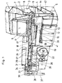
- eine mit einer erfindungsgemäßen Druckeinrichtung ausgestattete Zigarettenstrangmaschine;
- Fig. 2a bis 2c
- verschiedene perspektivische Ansichten einer erfindungsgemäßen Druckeinrichtung;
- Fig. 3a, 3b
- schematische Ansichten der Vorderansicht und Seitenansicht einer Druckeinrichtung;
- Fig. 4a, 4b
- eine alternative Ausführungsform einer Druckeinrichtung in einer Vorder- und Seitenansicht;
- Fig. 5
- schematisch einen Ausschnitt eines bedruckten Umhüllungsstreifens und
- Fig. 6a, 6b
- schematisch eine Trommelanordnung in einer Zigarettenansetzmaschine in einer Vorderansicht und Seitenansicht.
- Fig.1
- a cigarette rod machine equipped with a printing device according to the invention;
- Fig. 2a to 2c
- various perspective views of a printing device according to the invention;
- Fig. 3a, 3b
- schematic views of the front view and side view of a printing device;
- Fig. 4a, 4b
- an alternative embodiment of a printing device in a front and side view;
- Fig. 5
- schematically a section of a printed wrapping strip and
- Fig. 6a, 6b
- schematically a drum assembly in a cigarette slicer in a front view and side view.
In den Figuren sind jeweils gleiche oder gleichartige Elemente bzw. entsprechende Teile mit denselben Bezugsziffern versehen, so dass von einer entsprechenden erneuten Vorstellung abgesehen wird und lediglich Abweichungen der in diesen Figuren dargestellten Ausführungsbeispiele gegenüber dem ersten Ausführungsbeispiel erläutert werden.In the figures, identical or similar elements or corresponding parts are provided with the same reference numerals, so that a corresponding renewed idea is disregarded and only deviations of the exemplary embodiments illustrated in these figures from the first embodiment will be explained.
Bei der in
Aus dem Stauschacht 6 entnimmt eine Stiftwalze 7 einen gleichförmigen Tabakstrom, der von einer Ausschlagwalze 8 aus den Stiften der Stiftwalze 7 herausgeschlagen und auf ein mit konstanter Geschwindigkeit umlaufendes Streutuch 9 geschleudert wird. Ein auf dem Streutuch 9 gebildetes Tabakvlies wird in eine Sichteinrichtung 11 geschleudert, die im Wesentlichen aus einem Luftvorhang besteht, den größere bzw. schwerere Tabakteile passieren, während alle andere Tabakteilchen von der Luft in einen von einer Stiftwalze 12 und einer Wand 13 gebildeten Trichter 14 gelenkt werden.From the
Von der Stiftwalze 12 wird der Tabak in einen Tabakkanal 16 gegen einen Strangförderer 17 geschleudert, an dem der Tabak mittels in eine Unterdruckkammer 18 gesaugter Luft gehalten und ein Tabakstrang aufgeschauert wird.From the
Ein Egalisator 19 entfernt überschüssigen Tabak vom Tabakstrang, der dann auf einen im Gleichlauf geführten Zigarettenpapierstreifen 21 gelegt wird. Der Zigarettenpapierstreifen 21 wird von einer Bobine 22 abgezogen, durch eine Druckeinrichtung 23 geführt und auf ein angetriebenes Formatband 24 gelegt. Das Formatband 24 transportiert den Tabakstrang und den Zigarettenpapierstreifen 21 durch ein Format 26, in dem der Zigarettenpapierstreifen 21 um den Tabakstrang gefaltet wird, so dass noch eine Kante absteht, die von einem nicht dargestellten Leimapparat in bekannter Weise beleimt wird. Darauf wird die Klebnaht geschlossen und von einer Tandemnahtplätte 27 getrocknet.An
Ein so gebildeter Zigarettenstrang 28 durchläuft ein Strangdichtemessgerät 29, das den Egalisator 19 steuert, und wird von einem Messerapparat 31 in doppeltlange Zigaretten 32 geschnitten. Die doppeltiangen Zigaretten 32 werden von einer gesteuerte Arme 33 aufweisenden Übergabevorrichtung 34 einer Übernahmetrommel 36 einer Filteransetzmaschine 37 übergeben, auf deren Schneidtrommel 38 sie mit einem Kreismesser in Einzelzigaretten aufgeteilt werden.A thus formed
Förderbänder 39, 41 fördern überschüssigen Tabak in einen von dem Vorratsbehälter 4 angeordneten Behälter 42, aus dem der rückgeführte Tabak vom Steilförderer 5 wieder entnommen wird.
Bei der in
Bei der in den
In den
Die beiden Materialstreifen 210.1, 210.2 werden parallel und nebeneinander mittels zweier Umlenkrollen 50, 51 umgelenkt, so dass die Materialstreifen 210.1, 210.2 um einen rotierenden Zylinderkörper 60 anliegen und den Zylinderkörper 60 mit einem hohen Umschlingungsgrad umschlingen. Die Umlenkrolle 51 ist an einem Arm 52 angeordnet, so dass die Materialstreifen 210.1, 210.2 gut gespannt und faltenfrei auf der Mantelfläche des Zylinderkörpers 60 aufliegen.The two strips of material 210.1, 210.2 are deflected parallel and side by side by means of two
Um den Zylinderkörper 60 herum sind in regelmäßigen Abständen Druckköpfe 70 auf einem Drehkörper 71 angeordnet. Der Drehkörper 71 rotiert in dieselbe Richtung wie der Zylinderkörper 60. Während der Rotation des Zylinderkörpers 60 und des Drehkörpers 71 werden die Druckköpfe 70 senkrecht zur Drehrichtung bewegt, so dass während ihrer Hubbewegung Druckmarken auf den Materialstreifen 210.1, 210.2 aufgedruckt werden. Während einer vollständigen Umdrehung des Drehkörpers 71 wird eine volle Hubbewegung des Druckkopfs 70 mit einer Vorwärts- und Rückwärtsbewegung ausgeführt. Während dieser Vorwärts- und Rückwärtsbewegung werden die Druckmarken auf die Materialstreifen 210.1, 210.2 vollständig aufgedruckt.Around the
Als Druckköpfe werden beispielsweise Tintenstrahldruckköpfe verwendet, wobei die eingesetzte Tinte insbesondere den staatlichen Normen oder Tabakverordnungen entspricht. Um einen guten Tintenfluss zu gewährleisten, wird auf die Tinte im Behälter der Tintenpatronen ein, insbesondere geregelter, Druck ausgeübt, der den drehzahlabhängigen Zentrifugalkräften entgegenwirkt. Zwischen der Atmosphäre und der Tinte befindet sich hierfür eine Membran.As printheads, for example, inkjet printheads are used, the ink used in particular complies with state standards or tobacco regulations. In order to ensure a good ink flow, the ink in the container of the ink cartridges, in particular a regulated, pressure exerted, which counteracts the speed-dependent centrifugal forces. Between the atmosphere and the ink there is a membrane for this purpose.
Gemäß der Erfindung ist vorgesehen, dass die Rotationsgeschwindigkeit bzw. die Fördergeschwindigkeit der Druckköpfe 70 auf dem Drehkörper 71 und der Materialstreifen 210.1, 210.2 bzw. die Rotationsgeschwindigkeit des Zylinderkörpers 60 gleich sind, so dass zwischen den Materialstreifen 210.1, 210.2 und den jeweiligen Druckköpfen 70 keine Relativgeschwindigkeit besteht. Dadurch wird ein sicherer Aufdruck der Druckmarken auch bei einer hohen Fördergeschwindigkeit der Materialstreifen 210.1, 210.1 gewährleistet.According to the invention, it is provided that the rotational speed or the conveying speed of the printing heads 70 on the
Durch die Hubbewegung der Druckköpfe 70 wird erreicht, dass der Transportweg der Materialstreifen 210.1, 210.2 und der Druckköpfe 70 aneinander vorbei führen, da die Druckköpfe 70 in ihrem Umkehrpunkt unterhalb der Materialstreifen 210.1, 210.2 hindurch und vorbei gefördert werden.By the lifting movement of the print heads 70 it is achieved that the transport path of the material strips 210.1, 210.2 and the print heads 70 lead past each other, since the print heads 70 are conveyed in their reversal point below the strips of material 210.1, 210.2 through and past.
Nach vollständigem Bedrucken der Materialstreifen 210.1, 210.2 werden die beiden Materialstreifen 210.1, 210.2 über eine Umlenkrolle 53 jeweils einem Tabakstrang an einer doppelbahnigen Zigarettenstrangmaschine zugeführt.After complete printing of the material strips 210.1, 210.2, the two strips of material 210.1, 210.2 are each fed via a
Mit den regelmäßig angedeuteten Querstrichen auf den Materialstreifen 210.1, 210.2 sind jeweils die Längen eines Tabakstocks einfacher Länge angedeutet.With the regularly indicated cross strokes on the strip of material 210.1, 210.2, the lengths of a tobacco rod simple length are indicated in each case.
Die Druckmarken werden auf das mundseitige Ende der Materialstreifen 210.1, 210.2 der später gebildeten Tabakstöcke einfacher Länge aufgebracht. Hierzu werden die aneinander grenzenden Druckmarken spiegelverkehrt an der späteren Schnittstelle eines doppeltlangen Tabakstockes aufgedruckt. Hierzu weisen die Druckköpfe 70 zwei nebeneinander angeordnete Auftragspunkte auf.The print marks are applied to the mouth-side end of the material strips 210.1, 210.2 of the later-formed tobacco sticks of simple length. For this purpose, the contiguous print marks are printed mirror-inverted at the later interface of a double-length tobacco stick. For this purpose, the print heads 70 have two application points arranged next to one another.
In den
Im Rahmen der Erfindung ist es auch möglich, die Druckköpfe innerhalb des Zylinderkörpers 60 anzuordnen, so dass die Aufbringung der Druckmarken auf die Materialstreifen von innen erfolgt. In diesem Fall ist der von den Druckköpfen auszuführende Hub geringer, da in diesem Fall lediglich der Druckbereich abgedeckt werden muss und das Papier außen auf der Mantelfläche des Zylinderkörpers 60 umläuft.In the context of the invention, it is also possible to arrange the print heads within the
In
In den
Neben der Aufbringung eines Druckbildes, das auch mehrfarbig sein kann, können weitere information oder Sicherheitsinformationen für die Echtheit eines Produktes aufgedruckt werden.In addition to the application of a printed image, which can also be multicolored, further information or security information for the authenticity of a product can be printed.
In
Da der Druckkopf 70 über eine Druckbreite DB verfügt, kann der gesamte gestrichelte Bereich bedruckt werden. Insbesondere ist es möglich, den Überlappungsbereich von einem Belagpapierblättchen und einem Tabakstock zu beschreiben. Dieser Bereich ist mit der Bezugsziffer 122 bezeichnet. Da das Belagpapierblättchen um diese Verbindungsstelle herumgelegt wird, ist die aufgedruckte Information zu der Zigarette oder zur Herstellungsart usw. nicht sichtbar. Weitere Informationen über die Echtheit oder für die Qualitätssicherung können in der Nähe der Tabakstocknaht mittels des Druckkopfes 70 aufgebracht werden. Dieser Bereich ist mit der Bezugsziffer 123 versehen.Since the
Bei den in den
Hierbei werden Filterzigaretten einfacher Gebrauchslänge 90 von einer Fördertrommel 101 an eine Fördertrommel 102 übergeben. Auf dieser Fördertrommel 102 werden die Filterzigaretten 90 queraxial und senkrecht zur Transportrichtung verschoben und in die Aufnahmen 170 einer Drucktrommel 160 eingeschoben. Dies findet im Bereich II statt.In this case, filter cigarettes of
In den Arbeitsbereichen III, IV werden Aufdrucke auf das Zigarettenpapier der Filterzigaretten 90 aufgebracht, wobei beim Übergang vom Arbeitsbereich III zum Arbeitsbereich IV die Filterzigaretten ihren Endpunkt des Hubes H und Umkehrpunkt erreicht haben. Im Arbeitsbereich IV werden die Filterzigaretten 90 in die Gegenrichtung längsaxial transportiert, während der Aufdruck auf den Filterzigaretten 90 vervollständigt wird. Im Arbeitsbereich V werden die Zigaretten vollständig aus den Aufnahmen der Drucktrommel 160 herausgefahren und an eine Fördertrommel 103 übergeben.In the work areas III, IV imprints are applied to the cigarette paper of the
Die Drucktrommel 160 verfügt über einzelne Druckköpfe 170, deren Anzahl genau der Anzahl der Aufnahmen der Fördertrommel 102 entspricht. Die Drucktrommel 160 bewegt sich mit der gleichen Fördergeschwindigkeit wie die Fördertrommel 102, so dass zwischen den Druckköpfen 170 und den eingebrachten Filterzigaretten 90 keine Relativgeschwindigkeit besteht.The
Der mit der Erfindung erzielte Vorteil besteht darin, dass auf Artikeln der tabakverarbeitenden Industrie ein sauberes Druckbild auf die Artikel aufgebracht wird, wobei die Artikel mit einer hohen Fördergeschwindigkeit beispielsweise in einer Zigarettenstrangmaschine oder einer Filteransetzmaschine gefördert werden. Darüber hinaus lassen sich auch mehrfarbige Druckbilder auf den Artikeln realisieren.The advantage achieved by the invention is that on articles of the tobacco processing industry on a clean print image the article is applied, wherein the articles are conveyed at a high conveying speed, for example in a cigarette rod maker or a filter attachment machine. In addition, multicolored print images can be realized on the articles.
- 11
- Schleuselock
- 22
- Vorverteilerpreliminary distributor
- 33
- Entnahmewalzeout roller
- 44
- Vorratsbehälterreservoir
- 55
- Steilförderervertical conveyor
- 66
- Stauschachtaccumulating shaft
- 77
- Stiftwalzepin roll
- 88th
- Ausschlagwalzepicker roller
- 99
- Streutuchstray cloth
- 1111
- SichteinrichtungOverviewAmenitiesPicture
- 1313
- Bandtape
- 1414
- Trichterfunnel
- 1616
- Tabakkanaltobacco channel
- 1717
- Strangfördererline conveyor
- 1818
- UnterdruckkammerVacuum chamber
- 1919
- EgalisatorEgalisator
- 2121
- ZigarettenpapierstreifenCigarette paper strip
- 2222
- Bobinereel
- 2323
- Druckeinrichtungprint Setup
- 2424
- Formatbandformat tape
- 2626
- Formatformat
- 2727
- TandemnahtplätteTandemnahtplätte
- 2828
- Zigarettenstrangcigarette rod
- 2929
- StrangdichtemessgerätStrand density meter
- 3131
- Messerapparatknife apparatus
- 3232
- doppeltlange Zigarettendouble-length cigarettes
- 3333
- Armepoor
- 3434
- ÜbergabevorrichtungTransfer device
- 3636
- Übernahmetrommeltransfer drum
- 3737
- Filteransetzmaschinefilter attachment
- 3838
- Schneidtrommelcutting drum
- 3939
- Förderbandconveyor belt
- 4141
- Förderbandconveyor belt
- 4242
- Behältercontainer
- 5050
- Umlenkrolleidler pulley
- 5151
- Umlenkrolleidler pulley
- 5252
- Armpoor
- 5454
- Halterungbracket
- 1212
- Stiftwalzepin roll
- 6060
- Zylinderkörpercylinder body
- 7171
- Drehkörperrotating body
- 9090
- Filterzigarettenfilter cigarettes
- 100100
- Trommelanordnungbarrel assembly
- 101101
- Fördertrommelconveyor drum
- 102102
- Fördertrommelconveyor drum
- 103103
- Fördertrommelconveyor drum
- 121121
- Schnittlinieintersection
- 122122
- Überlappungsbereichoverlap area
- 123123
- Bereich (Tabakstocknaht)Area (tobacco stick seam)
- 160160
- Drucktrommelprint drum
- 170170
- Druckköpfeprintheads
- 210.1210.1
- Materialstreifenstrips of material
- 210.2210.2
- Materialstreifenstrips of material
- 230230
- Druckeinrichtungprint Setup
- II
- ArbeitsbereichWorkspace
- IIII
- ArbeitsbereichWorkspace
- IIIIII
- ArbeitsbereichWorkspace
- IVIV
- ArbeitsbereichWorkspace
- VV
- ArbeitsbereichWorkspace
- HH
- Hubstroke
- DBDB
- Druckbreiteprint width
Claims (21)
- Method of applying printed marks by means of a printing element (70, 170) onto an article (21, 210.1, 210.2; 90) of the tobacco processing industry, in particular a wrapping strip (21, 210.1, 210.2), preferably a cigarette paper strip or a rod-shaped smoker's article (90), which is being fed at a predetermined feed rate along a conveying direction, wherein along the conveying direction during the printing operation the relative speed between the printing element (70, 170) and the article (21, 210.1, 210.2; 90) is reduced, characterized in that the printing element (70, 170) and/or the article (21, 210.1, 210.2; 90) are moved transversely of, in particular at right angles to, the conveying direction, wherein the printing operation is effected transversely of the conveying direction of the article (21, 210.1, 210.2; 90).
- Method according to claim 1, characterized in that the printing element (70, 170) is moved along the conveying direction at an approximately identical rate or at the identical rate to the feed rate of the article (21, 210.1, 210.2; 90).
- Method according to claim 1 or 2, characterized in that the printing element (70, 170) and/or the article (21, 210.1, 210.2; 90) executes a forward- and a backward movement transversely of, in particular at right angles to, the conveying direction.
- Method according to one of claims 1 to 3, characterized in that the article (21, 210.1, 210.2; 90) is deflected, in particular in a loop-shaped manner, during the printing operation.
- Method according to one or more of claims 1 to 4, characterized in that the article (21, 210.1, 210.2; 90) during the printing operation is fed on a rotational body (60).
- Method according to one or more of claims 1 to 5, characterized in that the printing element (70, 170) is guided on a rotational body (71, 170).
- Method according to one or more of claims 1 to 6, characterized in that by means of the printing element (70, 170) a plurality of printed marks are printed onto the article (21, 210.1, 210.2).
- Method according to one or more of claims 1 to 7, characterized in that the printing element (70, 170) is programmed with printing data for the printed mark and/or printed marks.
- Method according to one or more of claims 1 to 8, characterized in that the printing element (70, 170) is exchanged after consumables of the printing element (70, 170) have been consumed.
- Method according to one or more of claims 1 to 9, characterized in that the printing element (70, 170) is adjusted for the printing operation.
- Device (23, 230) for applying printed marks onto an article (21, 210.1, 210.2; 90) of the tobacco processing industry, in particular a wrapping strip (21, 210.1, 210.2), preferably a cigarette paper strip or a rod-shaped smoker's article (90), comprising an article (21, 210.1, 210.2; 90) that is fed at a predetermined feed rate along a conveying direction and comprising a printing element (70, 170), wherein the printing element (70, 170) during the printing operation is movable along the conveying direction of the article (21, 210.1, 210.2; 90) in such a way that the relative speed between the printing element (70, 170) and the article (21, 210.1, 210.2; 90) is reduced, characterized in that the printing element (70, 170) and/or the article (21, 210.1, 210.2; 90) are movable transversely of, in particular at right angles to, the conveying direction, wherein the printing operation is effected transversely of the conveying direction of the article (21, 210.1, 210.2; 90).
- Device (23, 230) according to claim 11, characterized in that the printing element (70, 170) is movable along the conveying direction at an approximately identical rate or at the identical rate to the feed rate of the article (21, 210.1, 210.2; 90).
- Device (23, 230) according to claim 11 or 12, characterized in that the printing element (70, 170) and/or the article (21, 210.1, 210.2; 90) are movable forwards and backwards transversely, in particular at right angles.
- Device (23, 230) according to one of claims 11 to 13, characterized in that a device is provided for deflecting the article (21, 210.1, 210.2; 90), in particular in a loop-shaped manner, during the printing operation.
- Device (23, 230) according to one or more of claims 11 to 14, characterized in that a rotational body (60, 102) is provided for feeding the article (21, 210.1, 210.2; 90) during the printing operation.
- Device (23, 230) according to one or more of claims 11 to 15, characterized in that a rotational body (71, 160) is provided for the printing element (70, 170).
- Device (23, 230) according to one or more of claims 11 to 16, characterized in that a plurality of printing elements (70, 170) are provided.
- Device (23, 230) according to one or more of claims 12 to 17, characterized in that at least one printing element (70, 170) is programmable.
- Device (23, 230) according to one or more of claims 11 to 18, characterized in that at least one printing element (70, 170) is exchangeable.
- Device (23, 230) according to one or more of claims 11 to 19, characterized in that at least one printing element (70, 170) applies a multi-coloured printed mark onto the article (21, 210.1, 210.2; 90).
- Machine of the tobacco processing industry, in particular a cigarette rope machine or a filter attachment machine, having a device (23, 230) according to one or more of claims 11 to 20.
Priority Applications (2)
| Application Number | Priority Date | Filing Date | Title |
|---|---|---|---|
| EP04013074A EP1493339B1 (en) | 2003-07-01 | 2004-06-03 | Rotary printing unit for a machine of the tobacco processing industry |
| PL04013074T PL1493339T3 (en) | 2003-07-01 | 2004-06-03 | Rotary printing unit for a machine of the tobacco processing industry |
Applications Claiming Priority (3)
| Application Number | Priority Date | Filing Date | Title |
|---|---|---|---|
| EP03014930 | 2003-07-01 | ||
| EP03014930 | 2003-07-01 | ||
| EP04013074A EP1493339B1 (en) | 2003-07-01 | 2004-06-03 | Rotary printing unit for a machine of the tobacco processing industry |
Publications (2)
| Publication Number | Publication Date |
|---|---|
| EP1493339A1 EP1493339A1 (en) | 2005-01-05 |
| EP1493339B1 true EP1493339B1 (en) | 2010-02-24 |
Family
ID=33436115
Family Applications (1)
| Application Number | Title | Priority Date | Filing Date |
|---|---|---|---|
| EP04013074A Expired - Lifetime EP1493339B1 (en) | 2003-07-01 | 2004-06-03 | Rotary printing unit for a machine of the tobacco processing industry |
Country Status (2)
| Country | Link |
|---|---|
| EP (1) | EP1493339B1 (en) |
| PL (1) | PL1493339T3 (en) |
Families Citing this family (3)
| Publication number | Priority date | Publication date | Assignee | Title |
|---|---|---|---|---|
| DE102005044971B3 (en) * | 2005-09-20 | 2007-05-31 | Hauni Maschinenbau Ag | Printing a wrapping strip of the tobacco processing industry |
| WO2009018892A1 (en) † | 2007-08-03 | 2009-02-12 | Khs Ag | Device for printing containers |
| BRPI0817346B1 (en) | 2007-10-16 | 2019-10-08 | Khs Gmbh | CONTAINER CELL AND CONTAINER BASKET FOR A CONTAINER CLEANING MACHINE |
Family Cites Families (5)
| Publication number | Priority date | Publication date | Assignee | Title |
|---|---|---|---|---|
| US4635545A (en) * | 1984-12-24 | 1987-01-13 | American Can Company | Apparatus for marking moving articles |
| GB2250952B (en) | 1990-11-28 | 1994-02-16 | Harry Thomason | Apparatus for applying printed matter to objects |
| GB2302523B (en) | 1995-04-12 | 1998-03-25 | Prestek Ltd | Method of printing |
| US6598531B2 (en) * | 2001-05-09 | 2003-07-29 | Lasersoft Management, L.L.C. | Method and apparatus for on-demand production of digitally imaged webs |
| DE10130225A1 (en) | 2001-06-22 | 2003-01-02 | Hauni Maschinenbau Ag | Printing unit for applying printing marks on a wrapping strip of the tobacco processing industry |
-
2004
- 2004-06-03 PL PL04013074T patent/PL1493339T3/en unknown
- 2004-06-03 EP EP04013074A patent/EP1493339B1/en not_active Expired - Lifetime
Also Published As
| Publication number | Publication date |
|---|---|
| PL1493339T3 (en) | 2010-07-30 |
| EP1493339A1 (en) | 2005-01-05 |
Similar Documents
| Publication | Publication Date | Title |
|---|---|---|
| DE2818328C2 (en) | Process for the production of cigarette filter pieces | |
| DE3018982C2 (en) | ||
| DE102011106947A1 (en) | Machine and method for producing multiple filters | |
| DE4106127A1 (en) | METHOD AND DEVICE FOR PERFORATING CIGARETTE HELL MATERIAL | |
| DE2445856A1 (en) | METHOD AND APPARATUS FOR FORMING A TOBACCO STRAND FROM TWO TYPES OF TOBACCO | |
| DE659003C (en) | Method and machine for producing cigarettes with mouthpiece inserts | |
| EP1747730A1 (en) | Printing unit of the tobacco processing industry | |
| WO2006128551A1 (en) | Application of a liquid aroma substance to a material strip in the tobacco-processing industry | |
| EP1512541B1 (en) | Printer for a machine used in the tobacco industry | |
| EP1493339B1 (en) | Rotary printing unit for a machine of the tobacco processing industry | |
| EP1510142B1 (en) | Manipulation of rodlike articles from the tobacco manufacturing industry | |
| EP2062485B1 (en) | Printer with control of the rotational speed of a printing roller | |
| EP2783588A1 (en) | Cleaning of a machine for the tobacco processing industry | |
| WO2009000499A2 (en) | Printing group for a machine used in the tobacco processing industry | |
| DE2622449A1 (en) | METHOD AND DEVICE FOR MANUFACTURING FILTER CIGARETTES | |
| EP1397965A1 (en) | Injection of a medium in filter segments | |
| EP2532257B2 (en) | Transport drum for the tobacco processing industry | |
| DE102004031185A1 (en) | Process to impart ink jet mark to filter cigarettes by rotating wheel slowed during inkjet expulsion | |
| EP1691632B1 (en) | Oscillator for a printing group of the tobacco-processing industry | |
| WO2009090037A1 (en) | Printing group for a machine used in the tobacco industry | |
| EP1629735B1 (en) | Apparatus for feeding filters | |
| DE3013979A1 (en) | METHOD AND DEVICE FOR APPLYING GLUE ON A MOVING CONNECTION STRIP FOR SMOKE ITEMS | |
| DE69307191T2 (en) | Plant for the production of cigarettes | |
| DE2403531A1 (en) | DEVICE FOR FEEDING ROD-SHAPED ARTICLES OF THE TOBACCO-PROCESSING INDUSTRY FROM A STORAGE CONTAINER BORDERED BY TWO SIDE WALLS INTO A CIRCULAR RECEPTION DRUM | |
| EP0584716B1 (en) | Device for supplying compressed air to pneumatic engines which are connected to moving machine parts |
Legal Events
| Date | Code | Title | Description |
|---|---|---|---|
| PUAI | Public reference made under article 153(3) epc to a published international application that has entered the european phase |
Free format text: ORIGINAL CODE: 0009012 |
|
| AK | Designated contracting states |
Kind code of ref document: A1 Designated state(s): AT BE BG CH CY CZ DE DK EE ES FI FR GB GR HU IE IT LI LU MC NL PL PT RO SE SI SK TR |
|
| AX | Request for extension of the european patent |
Extension state: AL HR LT LV MK |
|
| 17P | Request for examination filed |
Effective date: 20050531 |
|
| AKX | Designation fees paid |
Designated state(s): AT BE BG CH CY CZ DE DK EE ES FI FR GB GR HU IE IT LI LU MC NL PL PT RO SE SI SK TR |
|
| 17Q | First examination report despatched |
Effective date: 20060912 |
|
| TPAC | Observations by third parties |
Free format text: ORIGINAL CODE: EPIDOSNTIPA |
|
| GRAP | Despatch of communication of intention to grant a patent |
Free format text: ORIGINAL CODE: EPIDOSNIGR1 |
|
| GRAS | Grant fee paid |
Free format text: ORIGINAL CODE: EPIDOSNIGR3 |
|
| GRAA | (expected) grant |
Free format text: ORIGINAL CODE: 0009210 |
|
| AK | Designated contracting states |
Kind code of ref document: B1 Designated state(s): AT BE BG CH CY CZ DE DK EE ES FI FR GB GR HU IE IT LI LU MC NL PL PT RO SE SI SK TR |
|
| REG | Reference to a national code |
Ref country code: GB Ref legal event code: FG4D Free format text: NOT ENGLISH |
|
| REG | Reference to a national code |
Ref country code: CH Ref legal event code: EP |
|
| REG | Reference to a national code |
Ref country code: IE Ref legal event code: FG4D Free format text: LANGUAGE OF EP DOCUMENT: GERMAN |
|
| REG | Reference to a national code |
Ref country code: NL Ref legal event code: T3 |
|
| REF | Corresponds to: |
Ref document number: 502004010795 Country of ref document: DE Date of ref document: 20100408 Kind code of ref document: P |
|
| RIN2 | Information on inventor provided after grant (corrected) |
Inventor name: OVERATH, MATTHIAS Inventor name: VOSS, HELMUT Inventor name: DOMBEK, MANFRED |
|
| PG25 | Lapsed in a contracting state [announced via postgrant information from national office to epo] |
Ref country code: PT Free format text: LAPSE BECAUSE OF FAILURE TO SUBMIT A TRANSLATION OF THE DESCRIPTION OR TO PAY THE FEE WITHIN THE PRESCRIBED TIME-LIMIT Effective date: 20100625 |
|
| REG | Reference to a national code |
Ref country code: PL Ref legal event code: T3 |
|
| PG25 | Lapsed in a contracting state [announced via postgrant information from national office to epo] |
Ref country code: FI Free format text: LAPSE BECAUSE OF FAILURE TO SUBMIT A TRANSLATION OF THE DESCRIPTION OR TO PAY THE FEE WITHIN THE PRESCRIBED TIME-LIMIT Effective date: 20100224 Ref country code: SI Free format text: LAPSE BECAUSE OF FAILURE TO SUBMIT A TRANSLATION OF THE DESCRIPTION OR TO PAY THE FEE WITHIN THE PRESCRIBED TIME-LIMIT Effective date: 20100224 |
|
| REG | Reference to a national code |
Ref country code: IE Ref legal event code: FD4D |
|
| PG25 | Lapsed in a contracting state [announced via postgrant information from national office to epo] |
Ref country code: SE Free format text: LAPSE BECAUSE OF FAILURE TO SUBMIT A TRANSLATION OF THE DESCRIPTION OR TO PAY THE FEE WITHIN THE PRESCRIBED TIME-LIMIT Effective date: 20100224 Ref country code: RO Free format text: LAPSE BECAUSE OF FAILURE TO SUBMIT A TRANSLATION OF THE DESCRIPTION OR TO PAY THE FEE WITHIN THE PRESCRIBED TIME-LIMIT Effective date: 20100224 Ref country code: IE Free format text: LAPSE BECAUSE OF FAILURE TO SUBMIT A TRANSLATION OF THE DESCRIPTION OR TO PAY THE FEE WITHIN THE PRESCRIBED TIME-LIMIT Effective date: 20100224 Ref country code: GR Free format text: LAPSE BECAUSE OF FAILURE TO SUBMIT A TRANSLATION OF THE DESCRIPTION OR TO PAY THE FEE WITHIN THE PRESCRIBED TIME-LIMIT Effective date: 20100525 Ref country code: ES Free format text: LAPSE BECAUSE OF FAILURE TO SUBMIT A TRANSLATION OF THE DESCRIPTION OR TO PAY THE FEE WITHIN THE PRESCRIBED TIME-LIMIT Effective date: 20100604 Ref country code: EE Free format text: LAPSE BECAUSE OF FAILURE TO SUBMIT A TRANSLATION OF THE DESCRIPTION OR TO PAY THE FEE WITHIN THE PRESCRIBED TIME-LIMIT Effective date: 20100224 Ref country code: CY Free format text: LAPSE BECAUSE OF FAILURE TO SUBMIT A TRANSLATION OF THE DESCRIPTION OR TO PAY THE FEE WITHIN THE PRESCRIBED TIME-LIMIT Effective date: 20100224 |
|
| PG25 | Lapsed in a contracting state [announced via postgrant information from national office to epo] |
Ref country code: CZ Free format text: LAPSE BECAUSE OF FAILURE TO SUBMIT A TRANSLATION OF THE DESCRIPTION OR TO PAY THE FEE WITHIN THE PRESCRIBED TIME-LIMIT Effective date: 20100224 Ref country code: SK Free format text: LAPSE BECAUSE OF FAILURE TO SUBMIT A TRANSLATION OF THE DESCRIPTION OR TO PAY THE FEE WITHIN THE PRESCRIBED TIME-LIMIT Effective date: 20100224 Ref country code: BG Free format text: LAPSE BECAUSE OF FAILURE TO SUBMIT A TRANSLATION OF THE DESCRIPTION OR TO PAY THE FEE WITHIN THE PRESCRIBED TIME-LIMIT Effective date: 20100524 |
|
| BERE | Be: lapsed |
Owner name: HAUNI MASCHINENBAU A.G. Effective date: 20100630 |
|
| PLBE | No opposition filed within time limit |
Free format text: ORIGINAL CODE: 0009261 |
|
| STAA | Information on the status of an ep patent application or granted ep patent |
Free format text: STATUS: NO OPPOSITION FILED WITHIN TIME LIMIT |
|
| PG25 | Lapsed in a contracting state [announced via postgrant information from national office to epo] |
Ref country code: MC Free format text: LAPSE BECAUSE OF NON-PAYMENT OF DUE FEES Effective date: 20100630 Ref country code: DK Free format text: LAPSE BECAUSE OF FAILURE TO SUBMIT A TRANSLATION OF THE DESCRIPTION OR TO PAY THE FEE WITHIN THE PRESCRIBED TIME-LIMIT Effective date: 20100224 |
|
| REG | Reference to a national code |
Ref country code: CH Ref legal event code: PL |
|
| 26N | No opposition filed |
Effective date: 20101125 |
|
| REG | Reference to a national code |
Ref country code: FR Ref legal event code: ST Effective date: 20110228 |
|
| PG25 | Lapsed in a contracting state [announced via postgrant information from national office to epo] |
Ref country code: LI Free format text: LAPSE BECAUSE OF NON-PAYMENT OF DUE FEES Effective date: 20100630 Ref country code: CH Free format text: LAPSE BECAUSE OF NON-PAYMENT OF DUE FEES Effective date: 20100630 |
|
| PG25 | Lapsed in a contracting state [announced via postgrant information from national office to epo] |
Ref country code: FR Free format text: LAPSE BECAUSE OF NON-PAYMENT OF DUE FEES Effective date: 20100630 |
|
| PG25 | Lapsed in a contracting state [announced via postgrant information from national office to epo] |
Ref country code: BE Free format text: LAPSE BECAUSE OF NON-PAYMENT OF DUE FEES Effective date: 20100630 |
|
| PG25 | Lapsed in a contracting state [announced via postgrant information from national office to epo] |
Ref country code: AT Free format text: LAPSE BECAUSE OF NON-PAYMENT OF DUE FEES Effective date: 20100603 |
|
| PG25 | Lapsed in a contracting state [announced via postgrant information from national office to epo] |
Ref country code: LU Free format text: LAPSE BECAUSE OF NON-PAYMENT OF DUE FEES Effective date: 20100603 Ref country code: HU Free format text: LAPSE BECAUSE OF FAILURE TO SUBMIT A TRANSLATION OF THE DESCRIPTION OR TO PAY THE FEE WITHIN THE PRESCRIBED TIME-LIMIT Effective date: 20100825 |
|
| PG25 | Lapsed in a contracting state [announced via postgrant information from national office to epo] |
Ref country code: TR Free format text: LAPSE BECAUSE OF FAILURE TO SUBMIT A TRANSLATION OF THE DESCRIPTION OR TO PAY THE FEE WITHIN THE PRESCRIBED TIME-LIMIT Effective date: 20100224 |
|
| PGFP | Annual fee paid to national office [announced via postgrant information from national office to epo] |
Ref country code: GB Payment date: 20130626 Year of fee payment: 10 |
|
| PGFP | Annual fee paid to national office [announced via postgrant information from national office to epo] |
Ref country code: IT Payment date: 20130620 Year of fee payment: 10 Ref country code: NL Payment date: 20130620 Year of fee payment: 10 |
|
| PGFP | Annual fee paid to national office [announced via postgrant information from national office to epo] |
Ref country code: DE Payment date: 20130701 Year of fee payment: 10 |
|
| PGFP | Annual fee paid to national office [announced via postgrant information from national office to epo] |
Ref country code: PL Payment date: 20130520 Year of fee payment: 10 |
|
| REG | Reference to a national code |
Ref country code: DE Ref legal event code: R119 Ref document number: 502004010795 Country of ref document: DE |
|
| REG | Reference to a national code |
Ref country code: NL Ref legal event code: V1 Effective date: 20150101 |
|
| GBPC | Gb: european patent ceased through non-payment of renewal fee |
Effective date: 20140603 |
|
| REG | Reference to a national code |
Ref country code: DE Ref legal event code: R119 Ref document number: 502004010795 Country of ref document: DE Effective date: 20150101 |
|
| PG25 | Lapsed in a contracting state [announced via postgrant information from national office to epo] |
Ref country code: NL Free format text: LAPSE BECAUSE OF NON-PAYMENT OF DUE FEES Effective date: 20150101 |
|
| PG25 | Lapsed in a contracting state [announced via postgrant information from national office to epo] |
Ref country code: DE Free format text: LAPSE BECAUSE OF NON-PAYMENT OF DUE FEES Effective date: 20150101 Ref country code: IT Free format text: LAPSE BECAUSE OF NON-PAYMENT OF DUE FEES Effective date: 20140603 |
|
| PG25 | Lapsed in a contracting state [announced via postgrant information from national office to epo] |
Ref country code: GB Free format text: LAPSE BECAUSE OF NON-PAYMENT OF DUE FEES Effective date: 20140603 |
|
| REG | Reference to a national code |
Ref country code: PL Ref legal event code: LAPE |
|
| PG25 | Lapsed in a contracting state [announced via postgrant information from national office to epo] |
Ref country code: PL Free format text: LAPSE BECAUSE OF NON-PAYMENT OF DUE FEES Effective date: 20140603 |