EP1493196B1 - Battery pack - Google Patents
Battery pack Download PDFInfo
- Publication number
- EP1493196B1 EP1493196B1 EP03746602A EP03746602A EP1493196B1 EP 1493196 B1 EP1493196 B1 EP 1493196B1 EP 03746602 A EP03746602 A EP 03746602A EP 03746602 A EP03746602 A EP 03746602A EP 1493196 B1 EP1493196 B1 EP 1493196B1
- Authority
- EP
- European Patent Office
- Prior art keywords
- frame
- cells
- battery pack
- endcap
- spine
- Prior art date
- Legal status (The legal status is an assumption and is not a legal conclusion. Google has not performed a legal analysis and makes no representation as to the accuracy of the status listed.)
- Expired - Lifetime
Links
- 125000003118 aryl group Chemical group 0.000 claims abstract description 16
- 229920000642 polymer Polymers 0.000 claims abstract description 16
- 229920000098 polyolefin Polymers 0.000 claims abstract description 13
- -1 polypropylene Polymers 0.000 claims abstract description 12
- 239000000203 mixture Substances 0.000 claims abstract description 6
- 239000012815 thermoplastic material Substances 0.000 claims abstract description 6
- 239000004743 Polypropylene Substances 0.000 claims abstract description 5
- 229920001155 polypropylene Polymers 0.000 claims abstract description 5
- 125000000524 functional group Chemical group 0.000 claims abstract description 4
- 239000011159 matrix material Substances 0.000 claims abstract description 3
- 238000000034 method Methods 0.000 claims description 7
- 239000000853 adhesive Substances 0.000 claims description 5
- 230000001070 adhesive effect Effects 0.000 claims description 5
- PXHVJJICTQNCMI-UHFFFAOYSA-N Nickel Chemical compound [Ni] PXHVJJICTQNCMI-UHFFFAOYSA-N 0.000 claims description 4
- 229920002480 polybenzimidazole Polymers 0.000 claims description 4
- 239000004793 Polystyrene Substances 0.000 claims description 3
- 229920002223 polystyrene Polymers 0.000 claims description 3
- WHXSMMKQMYFTQS-UHFFFAOYSA-N Lithium Chemical compound [Li] WHXSMMKQMYFTQS-UHFFFAOYSA-N 0.000 claims description 2
- 239000004962 Polyamide-imide Substances 0.000 claims description 2
- 239000004698 Polyethylene Substances 0.000 claims description 2
- 239000004642 Polyimide Substances 0.000 claims description 2
- 239000004734 Polyphenylene sulfide Substances 0.000 claims description 2
- 229920000292 Polyquinoline Polymers 0.000 claims description 2
- 229920003235 aromatic polyamide Polymers 0.000 claims description 2
- 229910052744 lithium Inorganic materials 0.000 claims description 2
- 229910052759 nickel Inorganic materials 0.000 claims description 2
- 229920002492 poly(sulfone) Polymers 0.000 claims description 2
- 229920002312 polyamide-imide Polymers 0.000 claims description 2
- 229920001230 polyarylate Polymers 0.000 claims description 2
- 229920002577 polybenzoxazole Polymers 0.000 claims description 2
- 229920000573 polyethylene Polymers 0.000 claims description 2
- 229920001721 polyimide Polymers 0.000 claims description 2
- 229920001470 polyketone Polymers 0.000 claims description 2
- 229920006389 polyphenyl polymer Polymers 0.000 claims description 2
- 229920000069 polyphenylene sulfide Polymers 0.000 claims description 2
- 229920005653 propylene-ethylene copolymer Polymers 0.000 claims description 2
- 239000006183 anode active material Substances 0.000 claims 1
- 239000006182 cathode active material Substances 0.000 claims 1
- 229920001601 polyetherimide Polymers 0.000 claims 1
- 229910052683 pyrite Inorganic materials 0.000 claims 1
- 238000003466 welding Methods 0.000 claims 1
- 238000003780 insertion Methods 0.000 abstract description 7
- 230000037431 insertion Effects 0.000 abstract description 7
- 239000000463 material Substances 0.000 abstract description 5
- 229920005992 thermoplastic resin Polymers 0.000 abstract description 5
- 229920006380 polyphenylene oxide Polymers 0.000 abstract description 3
- 229920001169 thermoplastic Polymers 0.000 abstract 1
- 239000004416 thermosoftening plastic Substances 0.000 abstract 1
- 210000004027 cell Anatomy 0.000 description 73
- 238000004519 manufacturing process Methods 0.000 description 4
- 229920000122 acrylonitrile butadiene styrene Polymers 0.000 description 3
- 238000005304 joining Methods 0.000 description 3
- AFFLGGQVNFXPEV-UHFFFAOYSA-N 1-decene Chemical compound CCCCCCCCC=C AFFLGGQVNFXPEV-UHFFFAOYSA-N 0.000 description 2
- LIKMAJRDDDTEIG-UHFFFAOYSA-N 1-hexene Chemical compound CCCCC=C LIKMAJRDDDTEIG-UHFFFAOYSA-N 0.000 description 2
- KWKAKUADMBZCLK-UHFFFAOYSA-N 1-octene Chemical compound CCCCCCC=C KWKAKUADMBZCLK-UHFFFAOYSA-N 0.000 description 2
- WSSSPWUEQFSQQG-UHFFFAOYSA-N 4-methyl-1-pentene Chemical compound CC(C)CC=C WSSSPWUEQFSQQG-UHFFFAOYSA-N 0.000 description 2
- KAKZBPTYRLMSJV-UHFFFAOYSA-N Butadiene Chemical compound C=CC=C KAKZBPTYRLMSJV-UHFFFAOYSA-N 0.000 description 2
- 239000004721 Polyphenylene oxide Substances 0.000 description 2
- PPBRXRYQALVLMV-UHFFFAOYSA-N Styrene Chemical compound C=CC1=CC=CC=C1 PPBRXRYQALVLMV-UHFFFAOYSA-N 0.000 description 2
- 238000001746 injection moulding Methods 0.000 description 2
- 239000000178 monomer Substances 0.000 description 2
- CCCMONHAUSKTEQ-UHFFFAOYSA-N octadec-1-ene Chemical compound CCCCCCCCCCCCCCCCC=C CCCMONHAUSKTEQ-UHFFFAOYSA-N 0.000 description 2
- YWAKXRMUMFPDSH-UHFFFAOYSA-N pentene Chemical compound CCCC=C YWAKXRMUMFPDSH-UHFFFAOYSA-N 0.000 description 2
- 239000004033 plastic Substances 0.000 description 2
- 229920003023 plastic Polymers 0.000 description 2
- 238000013022 venting Methods 0.000 description 2
- KPTMGJRRIXXKKW-UHFFFAOYSA-N 2,3,5-trimethyl-7-oxabicyclo[2.2.1]hepta-1,3,5-triene Chemical compound O1C2=C(C)C(C)=C1C=C2C KPTMGJRRIXXKKW-UHFFFAOYSA-N 0.000 description 1
- LXKCHCXZBPLTAE-UHFFFAOYSA-N 3,4-dimethyl-1H-pyrazole phosphate Chemical compound OP(O)(O)=O.CC1=CNN=C1C LXKCHCXZBPLTAE-UHFFFAOYSA-N 0.000 description 1
- GVLZQVREHWQBJN-UHFFFAOYSA-N 3,5-dimethyl-7-oxabicyclo[2.2.1]hepta-1,3,5-triene Chemical compound CC1=C(O2)C(C)=CC2=C1 GVLZQVREHWQBJN-UHFFFAOYSA-N 0.000 description 1
- YHQXBTXEYZIYOV-UHFFFAOYSA-N 3-methylbut-1-ene Chemical compound CC(C)C=C YHQXBTXEYZIYOV-UHFFFAOYSA-N 0.000 description 1
- LDTAOIUHUHHCMU-UHFFFAOYSA-N 3-methylpent-1-ene Chemical compound CCC(C)C=C LDTAOIUHUHHCMU-UHFFFAOYSA-N 0.000 description 1
- WNEYWVBECXCQRT-UHFFFAOYSA-N 5-methylhept-1-ene Chemical compound CCC(C)CCC=C WNEYWVBECXCQRT-UHFFFAOYSA-N 0.000 description 1
- JIUFYGIESXPUPL-UHFFFAOYSA-N 5-methylhex-1-ene Chemical compound CC(C)CCC=C JIUFYGIESXPUPL-UHFFFAOYSA-N 0.000 description 1
- NLHHRLWOUZZQLW-UHFFFAOYSA-N Acrylonitrile Chemical compound C=CC#N NLHHRLWOUZZQLW-UHFFFAOYSA-N 0.000 description 1
- 239000004727 Noryl Substances 0.000 description 1
- 229920001207 Noryl Polymers 0.000 description 1
- 229920010524 Syndiotactic polystyrene Polymers 0.000 description 1
- 229920001400 block copolymer Polymers 0.000 description 1
- 238000004891 communication Methods 0.000 description 1
- 230000000295 complement effect Effects 0.000 description 1
- 238000009826 distribution Methods 0.000 description 1
- 238000001493 electron microscopy Methods 0.000 description 1
- LDLDYFCCDKENPD-UHFFFAOYSA-N ethenylcyclohexane Chemical compound C=CC1CCCCC1 LDLDYFCCDKENPD-UHFFFAOYSA-N 0.000 description 1
- 238000002347 injection Methods 0.000 description 1
- 239000007924 injection Substances 0.000 description 1
- 238000002372 labelling Methods 0.000 description 1
- TVMXDCGIABBOFY-UHFFFAOYSA-N n-Octanol Natural products CCCCCCCC TVMXDCGIABBOFY-UHFFFAOYSA-N 0.000 description 1
- 229920001643 poly(ether ketone) Polymers 0.000 description 1
- 229920001652 poly(etherketoneketone) Polymers 0.000 description 1
- 229920006260 polyaryletherketone Polymers 0.000 description 1
- 229920006393 polyether sulfone Polymers 0.000 description 1
- 229920002530 polyetherether ketone Polymers 0.000 description 1
- 238000002360 preparation method Methods 0.000 description 1
- 229920005989 resin Polymers 0.000 description 1
- 239000011347 resin Substances 0.000 description 1
- 230000000087 stabilizing effect Effects 0.000 description 1
- 150000003457 sulfones Chemical class 0.000 description 1
- 230000007704 transition Effects 0.000 description 1
Images


Classifications
-
- H—ELECTRICITY
- H01—ELECTRIC ELEMENTS
- H01M—PROCESSES OR MEANS, e.g. BATTERIES, FOR THE DIRECT CONVERSION OF CHEMICAL ENERGY INTO ELECTRICAL ENERGY
- H01M50/00—Constructional details or processes of manufacture of the non-active parts of electrochemical cells other than fuel cells, e.g. hybrid cells
- H01M50/20—Mountings; Secondary casings or frames; Racks, modules or packs; Suspension devices; Shock absorbers; Transport or carrying devices; Holders
-
- H—ELECTRICITY
- H01—ELECTRIC ELEMENTS
- H01M—PROCESSES OR MEANS, e.g. BATTERIES, FOR THE DIRECT CONVERSION OF CHEMICAL ENERGY INTO ELECTRICAL ENERGY
- H01M50/00—Constructional details or processes of manufacture of the non-active parts of electrochemical cells other than fuel cells, e.g. hybrid cells
- H01M50/20—Mountings; Secondary casings or frames; Racks, modules or packs; Suspension devices; Shock absorbers; Transport or carrying devices; Holders
- H01M50/204—Racks, modules or packs for multiple batteries or multiple cells
- H01M50/207—Racks, modules or packs for multiple batteries or multiple cells characterised by their shape
- H01M50/213—Racks, modules or packs for multiple batteries or multiple cells characterised by their shape adapted for cells having curved cross-section, e.g. round or elliptic
-
- H—ELECTRICITY
- H01—ELECTRIC ELEMENTS
- H01M—PROCESSES OR MEANS, e.g. BATTERIES, FOR THE DIRECT CONVERSION OF CHEMICAL ENERGY INTO ELECTRICAL ENERGY
- H01M6/00—Primary cells; Manufacture thereof
- H01M6/42—Grouping of primary cells into batteries
- H01M6/44—Grouping of primary cells into batteries of tubular or cup-shaped cells
-
- H—ELECTRICITY
- H01—ELECTRIC ELEMENTS
- H01M—PROCESSES OR MEANS, e.g. BATTERIES, FOR THE DIRECT CONVERSION OF CHEMICAL ENERGY INTO ELECTRICAL ENERGY
- H01M2220/00—Batteries for particular applications
- H01M2220/30—Batteries in portable systems, e.g. mobile phone, laptop
-
- Y—GENERAL TAGGING OF NEW TECHNOLOGICAL DEVELOPMENTS; GENERAL TAGGING OF CROSS-SECTIONAL TECHNOLOGIES SPANNING OVER SEVERAL SECTIONS OF THE IPC; TECHNICAL SUBJECTS COVERED BY FORMER USPC CROSS-REFERENCE ART COLLECTIONS [XRACs] AND DIGESTS
- Y02—TECHNOLOGIES OR APPLICATIONS FOR MITIGATION OR ADAPTATION AGAINST CLIMATE CHANGE
- Y02E—REDUCTION OF GREENHOUSE GAS [GHG] EMISSIONS, RELATED TO ENERGY GENERATION, TRANSMISSION OR DISTRIBUTION
- Y02E60/00—Enabling technologies; Technologies with a potential or indirect contribution to GHG emissions mitigation
- Y02E60/10—Energy storage using batteries
Definitions
- the present invention generally relates to a battery pack, and more particularly relates to a battery pack for containing electrochemical cells.
- Battery packs containing electrochemical cells are in widespread use with a wide variety of portable electronic devices. Packs are utilized for a variety of reasons, including but not limited to the ease and efficiency of providing a series or a parallel connection for the cells as part of the pack, depending on the voltage provided by each cell and the power requirements of the device, thereby obviating the need for the device to provide the appropriate cell-to-cell contacts for accepting individual cells.
- Battery packs are typically made by joining one or more component pieces together.
- Such pack components can include cell receiving sections, one or more end caps and one or more terminals for making electrical connection between the cells and the device.
- the components may be welded together, adhesively joined together or snap fit together at some point in the manufacturing process.
- some packs may include an external adhesive label that provides a surface for conveying desired information concerning the pack and can also serve to hold the cells and the various structural pack components together in a single cohesive unit
- Such packs are disclosed, for example, in US-A- 5744260, issued 28 April, 1998; US-A- 4965148, issued 23 October 1990; and US -A-6218042, issued 17 April, 2001.
- WO-A-00/46865 discloses a battery pack comprising two electrochemical cells and a one piece integral frame made by injection moulding of a thermoplastic material ( Figures 4, 13, 16; page 18, line 18 to 22).
- the frame comprises two end cap portions and two spine portions.
- the first spine portion being connected to the first and second end cap portion, has a trapezoidal cross section and extends across the gap between the cells; in contrast to the present invention it has a single elevation along its entire length ( Figures 1, 2, 4, 13, 14B, 14C, 17; page 5, lines 11 to 18; page 19, lines 14 to 209; page 19, lines 14 to 23; page 22, lines 16 to 20).
- the second spine portion protrudes parallel to the first spine portion and one of its ends is free, allowing the spine to be flexed so as to provide an opening (page 7, line 9 to page 8, line 13; page 19, line 20 to page 20, line 2, Figures 1, 2, 4, 13, 16).
- the second spine portion is shorter than first spine portion and thus a dent is formed between the adjacent cells (page 7, line 9 to page 8, line 13; page 11, lines 1 to 8; page 19, line 20 to page 20, line 2; Figures 5, 6a-6d, 7a-7b, 14c, 15, 17).
- a guide rail of the electric appliance can be guided along the dent (page 25, line 21 to page 27, line 9; page 29, lines 7 to 12). Thus, improper insertion of the battery pack is prevented.
- a battery pack comprising a plurality of electrochemical cells and a battery receiving frame, said cells comprising external cell contact terminals, said frame comprising a first endcap portion, a second endcap portion, a first spine portion and a second spine portion, wherein said frame is a single integral part, said first spine portion has a first end connected to said first endcap portion and a second end connected to said second endcap portion and said first spine portion comprises two sections, each of the two sections having an external surface elevation different from the other.
- the battery pack comprises a battery pack frame.
- the battery pack frame is a single integral part.
- the frame comprises first and second endcap portions and first and second spine portions.
- One of the spine portions has a free end, allowing the spine to be flexed so as to provide an opening.
- the opening provided by the flexing of the spine may enable a cell assembly to be inserted into the frame, where a cell assembly comprises at least two cells and a cell-to-cell connection that provides either a series or a parallel connection between the cells.
- the flexing spine may have a length of at least fifty percent of the total length of the frame, thereby providing added support to the frame while still allowing for insertion of a cell assembly into the frame.
- the pack enables the use of the external cell contacts to provide an electrical connection directly to the device contacts, obviating the need for the pack to include discrete external terminals.
- the pack comprises two 1.5 volt standard sized AA cylindrical cells employing a lithium nonaqueous cell chemistry.
- the cells are connected in series by a simple nickel tab to create a 3.0 volt cell assembly.
- the untabbed positive terminal of one cell and the untabbed negative terminal of the second cell are accessible through one or more openings in an endcap portion and make electrical contact directly with the device terminals, thereby avoiding the complex additional tabbing required where 3.0 volt cells are connected in parallel.
- the present invention refers to a method of assembling a battery pack, comprising the steps of:
- the battery pack frame 10 includes a first endcap portion 12, a second endcap portion 14, a first spine portion 16 and a second spine portion 18.
- the frame 10 is designed to accommodate and position at least two cylindrical electrochemical cells arranged in two parallel rows within cell receiving areas. Cell receiving areas extend between the two endcap portions 12, 14. It should be appreciated, that the number of cells provided in the frame 10 of the battery pack is not critical and the frame may include less than a full complement of cells when more cells are not necessary for a given application.
- a battery pack according to the within invention comprises the frame 10, cells, and any optionally associated label.
- the battery pack frame 10 may be molded from a thermoplastic resin to form a single flexible part.
- the first spine portion 16 has a length extending between first endcap portion 12 and second endcap portion 14.
- the first spine portion 16 has a first end 20 connected to the first endcap portion 12 and a second end 22 connected the second endcap portion 14.
- the first spine portion 16 provides one or more external surfaces that cooperate with one or more surfaces of the battery pack compartment of a battery powered device.
- the first spine portion 16 optionally includes two sections 16A and 16B of differing elevations, to accommodate battery pack guides provided in the pack compartment of a device. It will be appreciated that the shape and configuration of these guides may vary from device to device, thus requiring the corresponding configuration of the first spine portion 16 to vary accordingly. Further, the width of the first spine portion 16 is not critical and may vary according to the particular requirements of the battery pack,the configuration of the pack compartment of a particular device and associated efforts to minimize the use of materials.
- the second spine portion 18 has a first end 24 connected to the first endcap portion 12 and a second end 26 that is free.
- the free second end 26 allows the second spine portion 18 to be flexed toward or away from the first spine portion 16, thereby creating an opening.
- an opening can also be created by flexing second endcap portion 14 away from the interior of the frame 10.
- two cells are connected by a tab to form a cell assembly prior to insertion into frame 10, and the opening created by flexing spine portion 18 accommodates this cell assembly and allows for insertion of such an assembly into the frame.
- discrete cells can be inserted into the frame 10, through an opening created by flexing the spine portion 18 or by flexing second endcap portion 14, or through other openings available in the frame.
- the second spine portion 18 provides a support structure for the battery pack frame 10. In some embodiments this may be accomplished when the length of second spine portion 18 is at least as great as fifty percent of the total length of the frame, or the length of the second spine portion 18 may be at least as great as seventy-five percent of the total length of the frame.
- the length of the second spine portion 18 is the dimension A as shown in Fig. 4. This dimension A is the distance between the exterior surface 28 of the first endcap portion 12 and the surface 30 of free end 26.
- the length of the frame 10 is the dimension B as shown in Fig. 4. This dimension B is the distance between the exterior surface 28 of the first endcap portion 12 and the exterior surface 32 of the second endcap portion 14.
- first endcap portion 12 may include a slot 34 within at least one of the cell receiving areas.
- the slot 34 accommodates the external cell terminal protrusion (typically the positive terminal) and also functions as a guide for any cell-to-cell tabbing that may be required as a result of the power and performance requirements for the battery pack.
- a tab may be welded to the positive external cell terminal protrusion of one cylindrical cell and the negative external cell terminal of a second cylindrical cell to make a cell assembly with a series connection; the cell assembly is then inserted into the cell receiving area of the frame and the welded positive terminal protrusion is positioned within the slot 34 of the endcap portion 12 of frame 10.
- the endcap portion 12 where the cell tabbing is located optionally includes an opening 36 defined by the slot structure.
- the opening 36 forms a venting path to the exterior of frame 10 and also provides a release point to separate the frame from the mold during manufacture of the frame 10.
- Second endcap portion 14 (Fig. 3) includes terminal openings 38A, 38B to expose the cell contacts that form the battery pack contacts, thereby providing electrical contact to the device terminals.
- the battery pack of the within invention there are no discrete pack terminals that must be joined or otherwise added to the pack to contact the device terminals. Rather, the terminals of the cells that are housed within the pack form the battery pack terminals and come into direct contact with the device terminals.
- the untabbed positive terminal protrusion of one of the series-connected cells is positioned so as to be exposed through opening 38A of second encap portion. 14, while the untabbed negative terminal of the other cell is positioned so as to be exposed through opening 38B.
- At least a portion of the perimeter of opening 38A is reinforced with a stabilizing support structure 40 having a centralized opening exposing the positive cell terminal protrusion.
- Support structure 40 can optionally include a gap 42. Gap 42 forms a venting path to the exterior of frame 10 and also provides a release point to separate the frame from the mold during manufacture of the frame 10.
- the frame is injection molded from a thermoplastic resin.
- Suitable thermoplastic resins include ABS resins (acrylonitrile, butadiene and styrene) such as Polylac ABS PA-717C and Polylac ABS PA-747 available from Entec Engineered Resins, Maitland, Florida, and Cycolac MG47 available from General Electric Plastics.
- thermoplastic resin utilized may be a mixture of - materials that includes at least one polyolefin and at least one aromatic polymer having a repeating unit with at least one aromatic functional group.
- the mixture may include more than 30 weight percent polyolefin, or it may contain at least 40 weight percent polyolefin.
- the polyolefin may be a polymer based on one or a combination of the following monomers: ethylene, propylene, 1-butene, 1-pentene, 1-hexene, 1-heptenc, 1-octene, 1-decene, 1-octadecene, 3-methyl-1-butene, 3-methyl-1-pentene, 4-methyl-1-pentene, 4-methyl-1-hexepe, 5-methyl-1-hexene, 5-methyl-1-heptene; vinylcyclohexane and vinymaphthalene.
- Polypropylene, polyethylene and polypropylene-ethylene copolymer may be advantageous in some embodiments.
- the mixture comprises discrete phases of the aromatic polymer in a matrix of the polyolefin, as can be observed with the aid of transition electron microscopy (TEM).
- TEM transition electron microscopy
- aromatic polymer is a polymer with a repeating unit that contains one or more types of aromatic functional groups.
- aromatic polymers that are suitable for use in the invention include poly(phenylene oxides), which have monomers such as 2,6-dimethyl-1,4-phenylene ether and 2,3,6-trimethyl-1,4-phenylene ether; aramids; polyketones, such as poly(ether ether ketone), poly(ether ketone), poly(ether ketone ketone) and poly(arylether ketone); polysulfones, such as polyether sulfones and polyaryl sulfones; polystyrenes, such as atactic polystyrene and syndiotactic polystyrene; polybenzimidazoles; polyimides; polybenzoxazinones; polybenzothiazoles; polybenzoxazoles; polybenzimidazoles; polyarylates; polyamide-imides; polyetheridmides; polyphen
- the thermoplastic material of the invention may optionally include a compatibilizer.
- a compatibilizer is a material that ties the polyolefin and aromatic polymer phases together to maintain the size, shape and distribution of the dispersed aromatic polymer in the polyolefin after injection molding of the seal member and throughout the useful life of the seal member and the cell in which it is used.
- Block copolymers are examples of compatibilizers that may be used. One end of a block is soluble in the polyolefin, and another end of a block is soluble in the aromatic polymer.
- the polyolefin is polypropylene and the aromatic polymer is polyphenylene oxide, such as is described in US Patent Application No. 09/033830, filed on 20 December 2001, and corresponding International Patent Application No. WO-A-02/39741, filed on 12 December 2002.
- One such polyphenylene oxide/polypropylene blend is Noryl PPX 7110, available from General Electric Plastics.
- cells can be inserted into the frame.
- Cell preparation prior to insertion into the frame can include shrink wrapping the cells individually, tabbing the cells together, providing any additional tabbing required to provide battery pack external contacts at the desired position in or on the pack, and joining the cells together using a suitable adhesive as is known in the art.
- the cells Once the cells have been prepared as desired, they can be inserted into the battery pack frame 10 by flexing the free end 26 of spine portion 18 toward or away from the interior of the frame, to create an opening sufficient to insert the cells into the frame.
- second endcap portion 14 can be flexed away from the interior of the frame, to create an opening for the insertion of cells into the frame.
- Figure 5 shows two cylindrical cells that have been inserted into frame 10. The positive protrusion 44 of one cell is exposed through opening 38A of second endcap portion 14 while the negative contact 46 of the second cell is exposed through opening 38B of second endcap portion 14. It will be appreciated by one of skill in the art that the frame 10 can be utilized with discrete cells that are not interconnected as well as with cells that are connected in series or in parallel.
- the integrity of the pack can be improved by the application of an adhesive label about the exterior of the exposed cell surfaces and the exposed surfaces of the frame.
- Figure 6 shows the battery pack of the within invention with the inclusion of an adhesive label 48 as is known in the art.
- the label also provides a surface available for the communication of information concerning the battery pack and its use.
Landscapes
- Chemical & Material Sciences (AREA)
- Chemical Kinetics & Catalysis (AREA)
- Electrochemistry (AREA)
- General Chemical & Material Sciences (AREA)
- Engineering & Computer Science (AREA)
- Manufacturing & Machinery (AREA)
- Battery Mounting, Suspending (AREA)
- Sealing Battery Cases Or Jackets (AREA)
Abstract
Description
- The present invention generally relates to a battery pack, and more particularly relates to a battery pack for containing electrochemical cells.
- Battery packs containing electrochemical cells are in widespread use with a wide variety of portable electronic devices. Packs are utilized for a variety of reasons, including but not limited to the ease and efficiency of providing a series or a parallel connection for the cells as part of the pack, depending on the voltage provided by each cell and the power requirements of the device, thereby obviating the need for the device to provide the appropriate cell-to-cell contacts for accepting individual cells.
- Battery packs are typically made by joining one or more component pieces together. Such pack components can include cell receiving sections, one or more end caps and one or more terminals for making electrical connection between the cells and the device. The components may be welded together, adhesively joined together or snap fit together at some point in the manufacturing process. Additionally, some packs may include an external adhesive label that provides a surface for conveying desired information concerning the pack and can also serve to hold the cells and the various structural pack components together in a single cohesive unit Such packs are disclosed, for example, in US-A- 5744260, issued 28 April, 1998; US-A- 4965148, issued 23 October 1990; and US -A-6218042, issued 17 April, 2001.
- WO-A-00/46865 discloses a battery pack comprising two electrochemical cells and a one piece integral frame made by injection moulding of a thermoplastic material (Figures 4, 13, 16;
page 18,line 18 to 22). The frame comprises two end cap portions and two spine portions. The first spine portion, being connected to the first and second end cap portion, has a trapezoidal cross section and extends across the gap between the cells; in contrast to the present invention it has a single elevation along its entire length (Figures 1, 2, 4, 13, 14B, 14C, 17; page 5, lines 11 to 18; page 19,lines 14 to 209; page 19,lines 14 to 23;page 22,lines 16 to 20). The second spine portion protrudes parallel to the first spine portion and one of its ends is free, allowing the spine to be flexed so as to provide an opening (page 7, line 9 to page 8, line 13; page 19,line 20 topage 20, line 2, Figures 1, 2, 4, 13, 16). The second spine portion is shorter than first spine portion and thus a dent is formed between the adjacent cells (page 7, line 9 to page 8, line 13; page 11, lines 1 to 8; page 19,line 20 topage 20, line 2; Figures 5, 6a-6d, 7a-7b, 14c, 15, 17). A guide rail of the electric appliance can be guided along the dent (page 25, line 21 to page 27, line 9; page 29, lines 7 to 12). Thus, improper insertion of the battery pack is prevented. - These packs present certain disadvantages. The required joining together of the structural pack components increases the potential for disassembly of the pack during labeling and other handling. Further, the number of structural pack components complicates the manufacturing and assembly processes.
- There is therefor a need for a pack that minimizes the number of component parts while maintaining sufficient structural integrity to protect the appropriate cell-to-cell contacts within the pack and provide a cohesive unit.
- Accordingly, it is an aspect of the present invention to provide a battery pack comprising a plurality of electrochemical cells and a battery receiving frame, said cells comprising external cell contact terminals, said frame comprising a first endcap portion, a second endcap portion, a first spine portion and a second spine portion, wherein said frame is a single integral part, said first spine portion has a first end connected to said first endcap portion and a second end connected to said second endcap portion and said first spine portion comprises two sections, each of the two sections having an external surface elevation different from the other. The battery pack comprises a battery pack frame. The battery pack frame is a single integral part. The frame comprises first and second endcap portions and first and second spine portions. One of the spine portions has a free end, allowing the spine to be flexed so as to provide an opening. The opening provided by the flexing of the spine may enable a cell assembly to be inserted into the frame, where a cell assembly comprises at least two cells and a cell-to-cell connection that provides either a series or a parallel connection between the cells. The flexing spine may have a length of at least fifty percent of the total length of the frame, thereby providing added support to the frame while still allowing for insertion of a cell assembly into the frame.
- The pack enables the use of the external cell contacts to provide an electrical connection directly to the device contacts, obviating the need for the pack to include discrete external terminals. In one embodiment of the battery pack of the within invention, the pack comprises two 1.5 volt standard sized AA cylindrical cells employing a lithium nonaqueous cell chemistry. In this embodiment, the cells are connected in series by a simple nickel tab to create a 3.0 volt cell assembly. The untabbed positive terminal of one cell and the untabbed negative terminal of the second cell are accessible through one or more openings in an endcap portion and make electrical contact directly with the device terminals, thereby avoiding the complex additional tabbing required where 3.0 volt cells are connected in parallel.
In a further embodiment the present invention refers to a method of assembling a battery pack, comprising the steps of: - providing a one-piece battery pack frame comprising first and second spine portions and first and second endcap portions, wherein a first end of said first spine portion is connected to said first endcap portion, a second end connected to said first spine portion is connected to said second endcap portion, said first spine portion comprises two sections, each of the two sections having an external surface elevation different from the other, and an end of said second spine portion is free;
- providing at least two electrochemical cells; and
- inserting said cells into said frame.
- The present invention will be further understood and appreciated by reference to the drawings, in which:
- Figure 1 is a perspective view of a frame of a battery pack according to the present invention;
- Figure 2 is a perspective view of one end of the battery pack frame of Fig. 1;
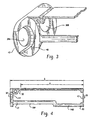
- Figure 3 is a perspective view of an opposing end of the battery pack frame of Fig. 1;
- Figure 4 is a side view of the battery pack frame of Fig. 1;
- Figure 5 is a perspective view of the battery pack frame of Figure 1 with two cylindrical cells inserted into the frame; and
- Figure 6 is a perspective view of the battery pack frame of Figure 5 with a label.
- An embodiment of a battery pack frame constructed in accordance with the present invention is illustrated in Figs. 1 through 4. The
battery pack frame 10 includes afirst endcap portion 12, asecond endcap portion 14, afirst spine portion 16 and asecond spine portion 18. Theframe 10 is designed to accommodate and position at least two cylindrical electrochemical cells arranged in two parallel rows within cell receiving areas. Cell receiving areas extend between the twoendcap portions frame 10 of the battery pack is not critical and the frame may include less than a full complement of cells when more cells are not necessary for a given application. A battery pack according to the within invention comprises theframe 10, cells, and any optionally associated label. - The
battery pack frame 10 may be molded from a thermoplastic resin to form a single flexible part. Thefirst spine portion 16 has a length extending betweenfirst endcap portion 12 andsecond endcap portion 14. Thefirst spine portion 16 has afirst end 20 connected to thefirst endcap portion 12 and asecond end 22 connected thesecond endcap portion 14. Thefirst spine portion 16 provides one or more external surfaces that cooperate with one or more surfaces of the battery pack compartment of a battery powered device. Thefirst spine portion 16 optionally includes twosections 16A and 16B of differing elevations, to accommodate battery pack guides provided in the pack compartment of a device. It will be appreciated that the shape and configuration of these guides may vary from device to device, thus requiring the corresponding configuration of thefirst spine portion 16 to vary accordingly. Further, the width of thefirst spine portion 16 is not critical and may vary according to the particular requirements of the battery pack,the configuration of the pack compartment of a particular device and associated efforts to minimize the use of materials. - The
second spine portion 18 has afirst end 24 connected to thefirst endcap portion 12 and asecond end 26 that is free. The freesecond end 26 allows thesecond spine portion 18 to be flexed toward or away from thefirst spine portion 16, thereby creating an opening. Optionally, an opening can also be created by flexingsecond endcap portion 14 away from the interior of theframe 10. In the one embodiment, two cells are connected by a tab to form a cell assembly prior to insertion intoframe 10, and the opening created by flexingspine portion 18 accommodates this cell assembly and allows for insertion of such an assembly into the frame. Optionally, discrete cells can be inserted into theframe 10, through an opening created by flexing thespine portion 18 or by flexingsecond endcap portion 14, or through other openings available in the frame. - The
second spine portion 18 provides a support structure for thebattery pack frame 10. In some embodiments this may be accomplished when the length ofsecond spine portion 18 is at least as great as fifty percent of the total length of the frame, or the length of thesecond spine portion 18 may be at least as great as seventy-five percent of the total length of the frame. The length of thesecond spine portion 18 is the dimension A as shown in Fig. 4. This dimension A is the distance between theexterior surface 28 of thefirst endcap portion 12 and thesurface 30 offree end 26. The length of theframe 10 is the dimension B as shown in Fig. 4. This dimension B is the distance between theexterior surface 28 of thefirst endcap portion 12 and theexterior surface 32 of thesecond endcap portion 14. - In an embodiment of the invention, a cell assembly with two cells connected in series is inserted into the
frame 10. In this embodiment, the interior of first endcap portion 12 (Fig. 2) may include aslot 34 within at least one of the cell receiving areas. Theslot 34 accommodates the external cell terminal protrusion (typically the positive terminal) and also functions as a guide for any cell-to-cell tabbing that may be required as a result of the power and performance requirements for the battery pack. A tab may be welded to the positive external cell terminal protrusion of one cylindrical cell and the negative external cell terminal of a second cylindrical cell to make a cell assembly with a series connection; the cell assembly is then inserted into the cell receiving area of the frame and the welded positive terminal protrusion is positioned within theslot 34 of theendcap portion 12 offrame 10. The endcapportion 12 where the cell tabbing is located optionally includes anopening 36 defined by the slot structure. The opening 36 forms a venting path to the exterior offrame 10 and also provides a release point to separate the frame from the mold during manufacture of theframe 10. - Second endcap portion 14 (Fig. 3) includes
terminal openings opening 38A of second encap portion. 14, while the untabbed negative terminal of the other cell is positioned so as to be exposed throughopening 38B. In some embodiments at least a portion of the perimeter of opening 38A is reinforced with a stabilizingsupport structure 40 having a centralized opening exposing the positive cell terminal protrusion.Support structure 40 can optionally include agap 42.Gap 42 forms a venting path to the exterior offrame 10 and also provides a release point to separate the frame from the mold during manufacture of theframe 10. - In one embodiment, the frame is injection molded from a thermoplastic resin. Suitable thermoplastic resins include ABS resins (acrylonitrile, butadiene and styrene) such as Polylac ABS PA-717C and Polylac ABS PA-747 available from Entec Engineered Resins, Maitland, Florida, and Cycolac MG47 available from General Electric Plastics.
- In some embodiments the thermoplastic resin utilized may be a mixture of - materials that includes at least one polyolefin and at least one aromatic polymer having a repeating unit with at least one aromatic functional group. The mixture may include more than 30 weight percent polyolefin, or it may contain at least 40 weight percent polyolefin.
- The polyolefin may be a polymer based on one or a combination of the following monomers: ethylene, propylene, 1-butene, 1-pentene, 1-hexene, 1-heptenc, 1-octene, 1-decene, 1-octadecene, 3-methyl-1-butene, 3-methyl-1-pentene, 4-methyl-1-pentene, 4-methyl-1-hexepe, 5-methyl-1-hexene, 5-methyl-1-heptene; vinylcyclohexane and vinymaphthalene. Polypropylene, polyethylene and polypropylene-ethylene copolymer may be advantageous in some embodiments.
- The mixture comprises discrete phases of the aromatic polymer in a matrix of the polyolefin, as can be observed with the aid of transition electron microscopy (TEM).
- An aromatic polymer is a polymer with a repeating unit that contains one or more types of aromatic functional groups. Examples of aromatic polymers that are suitable for use in the invention include poly(phenylene oxides), which have monomers such as 2,6-dimethyl-1,4-phenylene ether and 2,3,6-trimethyl-1,4-phenylene ether; aramids; polyketones, such as poly(ether ether ketone), poly(ether ketone), poly(ether ketone ketone) and poly(arylether ketone); polysulfones, such as polyether sulfones and polyaryl sulfones; polystyrenes, such as atactic polystyrene and syndiotactic polystyrene; polybenzimidazoles; polyimides; polybenzoxazinones; polybenzothiazoles; polybenzoxazoles; polybenzimidazoles; polyarylates; polyamide-imides; polyetheridmides; polyphenylene sulfides; polyphenyls; polyquinolines; and polyquinoxalines. Poly(phenylene oxides) may also be used.
- The thermoplastic material of the invention may optionally include a compatibilizer. A compatibilizer is a material that ties the polyolefin and aromatic polymer phases together to maintain the size, shape and distribution of the dispersed aromatic polymer in the polyolefin after injection molding of the seal member and throughout the useful life of the seal member and the cell in which it is used. Block copolymers are examples of compatibilizers that may be used. One end of a block is soluble in the polyolefin, and another end of a block is soluble in the aromatic polymer.
- In an embodiment of the invention, the polyolefin is polypropylene and the aromatic polymer is polyphenylene oxide, such as is described in US Patent Application No. 09/033830, filed on 20 December 2001, and corresponding International Patent Application No. WO-A-02/39741, filed on 12 December 2002. One such polyphenylene oxide/polypropylene blend is Noryl PPX 7110, available from General Electric Plastics.
- Once the
battery pack frame 10 has been molded, cells can be inserted into the frame. Cell preparation prior to insertion into the frame can include shrink wrapping the cells individually, tabbing the cells together, providing any additional tabbing required to provide battery pack external contacts at the desired position in or on the pack, and joining the cells together using a suitable adhesive as is known in the art. Once the cells have been prepared as desired, they can be inserted into thebattery pack frame 10 by flexing thefree end 26 ofspine portion 18 toward or away from the interior of the frame, to create an opening sufficient to insert the cells into the frame. Alternately, or in addition to flexing thefree end 26 ofspine portion 18,second endcap portion 14 can be flexed away from the interior of the frame, to create an opening for the insertion of cells into the frame. Figure 5 shows two cylindrical cells that have been inserted intoframe 10. Thepositive protrusion 44 of one cell is exposed throughopening 38A ofsecond endcap portion 14 while thenegative contact 46 of the second cell is exposed throughopening 38B ofsecond endcap portion 14. It will be appreciated by one of skill in the art that theframe 10 can be utilized with discrete cells that are not interconnected as well as with cells that are connected in series or in parallel. - Optionally, the integrity of the pack can be improved by the application of an adhesive label about the exterior of the exposed cell surfaces and the exposed surfaces of the frame. Figure 6 shows the battery pack of the within invention with the inclusion of an
adhesive label 48 as is known in the art. The label also provides a surface available for the communication of information concerning the battery pack and its use.
Claims (16)
- A battery pack comprising a plurality of electrochemical cells and a battery receiving frame (10), said cells comprising external cell contact terminals, said frame comprising a first endcap portion (12), a second endcap portion (14), a first spine portion (16) and a second spine portion (18), wherein said frame is a single integral part, said first spine portion (16) has a first end (20) connected to said first endcap portion (12) and a second end (22) connected to said second endcap portion (14) and said first spine portion (16) comprises two sections (15A, 16B), each of the two sections (16A, 16B) having an external surface elevation different from the other.
- The battery pack of claim 1, wherein said second spine portion (18) has a first end (24) connected to said first endcap portion (12) and a second end (26) that is free.
- The battery pack of any preceding claim, wherein said second endcap portion (14) further comprises at least one opening (38A, 38B) exposing at least one of the cell contact terminals to the exterior of the pack.
- The battery pack of any preceding claim, wherein said first endcap portion (12) further comprises at least one opening (38A, 38B) exposing at least one of the cell contact terminals to the exterior of the pack.
- The battery pack of any of claims 2 to 4, wherein said second spine portion (18) has a length between said first and second ends (20, 22) that is at least as great as half of the total length of the frame (10).
- The battery pack of any preceding claim, wherein said cells are cylindrical cells and at least two of said cells are connected in series.
- The battery pack of claim 6, wherein said cells are standard size AA cells.
- The battery pack of any preceding claim, wherein said cells comprise metallic lithium as the anode active material and iron pyrite as the cathode active material.
- The battery pack of claim 1 wherein said frame (10) comprises an injection-molded thermoplastic material, the thermoplastic material comprising a mixture of:a polyolefin matrix comprising more than 30 weight percent of the thermoplastic material; andan aromatic polymer having a repeating unit that comprises at least one aromatic functional group.
- The battery pack of claim 9, wherein the polyolefin is at least one polymer selected from the group consisting of a polypropylene, a polyethylene, and a polypropylene-ethylene copolymer.
- The battery pack of daims 9 or 10, wherein the aromatic polymer is at least one polymer selected from the group consisting of poly(phenylene oxides), aramids, polyketones, polysulfones, polystyrenes, polybenzimidazoles, polyimides, polybenzoxazinones, polybenzothiazoles, polybenzoxazoles, polybenzimidazoles, polyarylates, polyamide-imides, polyetherimides, polyphenylene sulfides, polyphenyls, polyquinolines and polyquinoxalines.
- A method of assembling a battery pack, comprising the steps of:providing a one-piece battery pack frame (10) comprising first and second spine portions (16, 18) and first and second endcap portions (12, 14), wherein a first end of said first spine portion (16) is connected to said first endcap portion (12), a second end (22) connected to said first spine portion (16) is connected to said second endcap portion (14), said first spine portion (16) comprises two sections (16A, 16B), each of the two sections having an external surface elevation different from the other, and an end of said second spine portion (18) is free;providing at least two electrochemical cells; andinserting said cells into said frame.
- The method of claim 12, further including the steps of creating a connection between said cells prior to inserting said cells into said frame (10) and flexing said free end to create an opening sufficient to insert said cells into said frame (10).
- The method of claim 12, wherein said connection is created by welding a nickel tab to the positive terminal of one cell and the negative terminal of another cell.
- The method of any of claims 12 to 14, further including the step of applying a shrink wrap to said cells prior to inserting said cells into said frame (10).
- The method of any of claims 12 to 15, further including the step of applying an adhesive label to portions of the external surfaces of said frame (10) and to portions of the exposed external surfaces of said cells.
Applications Claiming Priority (3)
| Application Number | Priority Date | Filing Date | Title |
|---|---|---|---|
| US120912 | 2002-04-11 | ||
| US10/120,912 US6811922B2 (en) | 2002-04-11 | 2002-04-11 | Battery pack |
| PCT/US2003/010386 WO2003088377A2 (en) | 2002-04-11 | 2003-04-04 | Battery pack |
Publications (2)
| Publication Number | Publication Date |
|---|---|
| EP1493196A2 EP1493196A2 (en) | 2005-01-05 |
| EP1493196B1 true EP1493196B1 (en) | 2006-01-04 |
Family
ID=28790201
Family Applications (1)
| Application Number | Title | Priority Date | Filing Date |
|---|---|---|---|
| EP03746602A Expired - Lifetime EP1493196B1 (en) | 2002-04-11 | 2003-04-04 | Battery pack |
Country Status (10)
| Country | Link |
|---|---|
| US (1) | US6811922B2 (en) |
| EP (1) | EP1493196B1 (en) |
| JP (1) | JP4480403B2 (en) |
| KR (1) | KR100962636B1 (en) |
| CN (1) | CN1298064C (en) |
| AT (1) | ATE315276T1 (en) |
| AU (1) | AU2003262122A1 (en) |
| CA (1) | CA2481032C (en) |
| DE (1) | DE60303139T2 (en) |
| WO (1) | WO2003088377A2 (en) |
Families Citing this family (11)
| Publication number | Priority date | Publication date | Assignee | Title |
|---|---|---|---|---|
| CN2819483Y (en) * | 2005-04-15 | 2006-09-20 | 金达时发展有限公司 | Combinable connecting frame for thin-plate lithium battery |
| USD532371S1 (en) * | 2005-08-23 | 2006-11-21 | Sony Corporation | Battery charger |
| KR101156531B1 (en) | 2005-12-07 | 2012-06-20 | 삼성에스디아이 주식회사 | Method for Preparing a Flexible Semiconductor Electrode, Semiconductor Electrode Prepared by the Same and Solar Cell using the Same |
| KR100930474B1 (en) | 2005-12-08 | 2009-12-09 | 주식회사 엘지화학 | Assembly spacer for battery module manufacturing |
| KR101016870B1 (en) * | 2009-09-18 | 2011-02-22 | 삼성에스디아이 주식회사 | Packing method of secondary battery and mold apparatus used therefor |
| DE102010061865A1 (en) | 2010-11-24 | 2012-05-24 | Behr Gmbh & Co. Kg | Frame for an electrochemical energy storage unit |
| US9548476B2 (en) * | 2010-12-20 | 2017-01-17 | Samsung Sdi Co., Ltd. | Multi-cell battery module with integral cooling and assembly aids |
| US9172115B2 (en) | 2012-06-12 | 2015-10-27 | Milwaukee Electric Tool Corporation | Battery pack with multiple water discharge pathways |
| US9991753B2 (en) * | 2014-06-11 | 2018-06-05 | Enovate Medical Llc | Variable wireless transfer |
| CN109713189B (en) * | 2019-01-29 | 2024-07-26 | 四川中科兴业高新材料有限公司 | Lower box body of benzoxazine composite material new energy automobile lightweight battery box |
| KR102890553B1 (en) | 2020-06-29 | 2025-11-26 | 주식회사 엘지에너지솔루션 | Manufacturing Method Of Battery Modules To Prevent Thermal Runaway Propagation |
Family Cites Families (14)
| Publication number | Priority date | Publication date | Assignee | Title |
|---|---|---|---|---|
| US4020245A (en) * | 1974-11-06 | 1977-04-26 | Mabuchi Motor Co. Ltd. | Cell adapter |
| JPS5790868A (en) * | 1980-11-27 | 1982-06-05 | Seiko Instr & Electronics Ltd | Non-aqueous electrolyte battery |
| FR2562722B1 (en) * | 1984-04-06 | 1987-04-24 | Black & Decker Inc | PROCESS AND DEVICE FOR MANUFACTURING AN ELECTRICAL ACCUMULATOR ASSEMBLY COMPRISING A PLURALITY OF RECHARGEABLE ACCUMULATORS |
| JPH0690921B2 (en) * | 1988-09-28 | 1994-11-14 | 松下電器産業株式会社 | Battery pack and manufacturing method |
| USD408351S (en) * | 1996-04-29 | 1999-04-20 | Daewoo Electronics Co., Ltd. | Battery case |
| USD409560S (en) * | 1996-04-29 | 1999-05-11 | Daewoo Electronics Co., Ltd. | Battery case |
| USD409559S (en) * | 1996-04-29 | 1999-05-11 | Daewoo Electronics Co., Ltd. | Battery case |
| US5744260A (en) * | 1996-07-25 | 1998-04-28 | Daewoo Electronics Co., Ltd. | Battery pack |
| US5709963A (en) * | 1996-07-25 | 1998-01-20 | Daewoo Electronics Co., Inc. | Battery pack |
| JPH1069892A (en) | 1996-08-27 | 1998-03-10 | Matsushita Electric Ind Co Ltd | Battery pack |
| US6014009A (en) * | 1997-04-25 | 2000-01-11 | Data General Corporation | Electronic device |
| FR2762716B1 (en) * | 1997-04-28 | 1999-05-28 | Alsthom Cge Alcatel | DEVICE FOR ASSEMBLING BATTERIES OF ELECTROCHEMICAL GENERATORS |
| JP3863693B2 (en) * | 1999-02-01 | 2006-12-27 | 松下電器産業株式会社 | Pack battery |
| JP2001307610A (en) * | 2000-04-17 | 2001-11-02 | Sanyo Electric Co Ltd | Method of manufacturing fuse and battery pack incorporating this fuse |
-
2002
- 2002-04-11 US US10/120,912 patent/US6811922B2/en not_active Expired - Fee Related
-
2003
- 2003-04-04 CN CNB03813201XA patent/CN1298064C/en not_active Expired - Fee Related
- 2003-04-04 CA CA2481032A patent/CA2481032C/en not_active Expired - Fee Related
- 2003-04-04 EP EP03746602A patent/EP1493196B1/en not_active Expired - Lifetime
- 2003-04-04 AU AU2003262122A patent/AU2003262122A1/en not_active Abandoned
- 2003-04-04 JP JP2003585199A patent/JP4480403B2/en not_active Expired - Fee Related
- 2003-04-04 KR KR1020047016265A patent/KR100962636B1/en not_active Expired - Fee Related
- 2003-04-04 AT AT03746602T patent/ATE315276T1/en not_active IP Right Cessation
- 2003-04-04 WO PCT/US2003/010386 patent/WO2003088377A2/en not_active Ceased
- 2003-04-04 DE DE60303139T patent/DE60303139T2/en not_active Expired - Lifetime
Also Published As
| Publication number | Publication date |
|---|---|
| CA2481032C (en) | 2011-01-25 |
| JP2005527077A (en) | 2005-09-08 |
| CN1298064C (en) | 2007-01-31 |
| HK1074279A1 (en) | 2005-11-04 |
| US20030193315A1 (en) | 2003-10-16 |
| EP1493196A2 (en) | 2005-01-05 |
| WO2003088377A8 (en) | 2005-04-21 |
| CA2481032A1 (en) | 2003-10-23 |
| CN1659725A (en) | 2005-08-24 |
| AU2003262122A1 (en) | 2003-10-27 |
| JP4480403B2 (en) | 2010-06-16 |
| ATE315276T1 (en) | 2006-02-15 |
| WO2003088377A2 (en) | 2003-10-23 |
| KR100962636B1 (en) | 2010-06-11 |
| KR20050000384A (en) | 2005-01-03 |
| US6811922B2 (en) | 2004-11-02 |
| DE60303139T2 (en) | 2006-08-24 |
| WO2003088377A3 (en) | 2004-08-12 |
| AU2003262122A8 (en) | 2003-10-27 |
| DE60303139D1 (en) | 2006-03-30 |
Similar Documents
| Publication | Publication Date | Title |
|---|---|---|
| EP1493196B1 (en) | Battery pack | |
| EP0612116B1 (en) | Support extension for flat pack rechargeable batteries | |
| KR100850866B1 (en) | Frame member for battery pack manufacturing | |
| EP0977289B1 (en) | A secondary battery in a case | |
| KR100980104B1 (en) | Secondary Battery Manufacturing Equipment | |
| KR102392729B1 (en) | Battery plates useful in bipolar battery assemblies and methods of preparation | |
| US4800142A (en) | Electric storage battery | |
| CN101404325B (en) | Cap assembly and secondary battery using the same | |
| KR20150142073A (en) | Bipolar battery assembly | |
| KR20000066414A (en) | Secondary battery | |
| KR20210060640A (en) | Battery cell interconnection system | |
| US8524391B2 (en) | Rechargeable battery pack | |
| CA2048985C (en) | Bipolar battery and assembly method | |
| JP2005527077A5 (en) | ||
| HK1074279B (en) | Battery pack | |
| EP0476740A1 (en) | Bipolar battery and assembly method | |
| KR20220163007A (en) | Interbus bar assembly and battery module connection structure and connection structure of battery module-relay box including the same | |
| KR100614278B1 (en) | Built-in battery pack for mobile communication terminal | |
| EP1946421A1 (en) | Prefabricated pcm and battery pack containing the same | |
| GB2158285A (en) | Multicell electric storage batteries | |
| EP4404363A1 (en) | Battery cell, and battery pack and vehicle including same | |
| KR100496433B1 (en) | Lithium ion secondry battery | |
| KR100322097B1 (en) | Secondary battery | |
| EP4629418A1 (en) | Battery pack | |
| KR20070033836A (en) | Pack battery |
Legal Events
| Date | Code | Title | Description |
|---|---|---|---|
| PUAI | Public reference made under article 153(3) epc to a published international application that has entered the european phase |
Free format text: ORIGINAL CODE: 0009012 |
|
| 17P | Request for examination filed |
Effective date: 20041001 |
|
| AK | Designated contracting states |
Kind code of ref document: A2 Designated state(s): AT BE BG CH CY CZ DE DK EE ES FI FR GB GR HU IE IT LI LU MC NL PT RO SE SI SK TR |
|
| AX | Request for extension of the european patent |
Extension state: AL LT LV MK |
|
| RIN1 | Information on inventor provided before grant (corrected) |
Inventor name: SINKEWICH, LAWRENCE Inventor name: SHEA, THOMAS Inventor name: MADJAR, SILVESTER |
|
| GRAP | Despatch of communication of intention to grant a patent |
Free format text: ORIGINAL CODE: EPIDOSNIGR1 |
|
| 17Q | First examination report despatched |
Effective date: 20050406 |
|
| GRAS | Grant fee paid |
Free format text: ORIGINAL CODE: EPIDOSNIGR3 |
|
| REG | Reference to a national code |
Ref country code: HK Ref legal event code: DE Ref document number: 1074279 Country of ref document: HK |
|
| GRAA | (expected) grant |
Free format text: ORIGINAL CODE: 0009210 |
|
| AK | Designated contracting states |
Kind code of ref document: B1 Designated state(s): AT BE BG CH CY CZ DE DK EE ES FI FR GB GR HU IE IT LI LU MC NL PT RO SE SI SK TR |
|
| PG25 | Lapsed in a contracting state [announced via postgrant information from national office to epo] |
Ref country code: IT Free format text: LAPSE BECAUSE OF FAILURE TO SUBMIT A TRANSLATION OF THE DESCRIPTION OR TO PAY THE FEE WITHIN THE PRESCRIBED TIME-LIMIT;WARNING: LAPSES OF ITALIAN PATENTS WITH EFFECTIVE DATE BEFORE 2007 MAY HAVE OCCURRED AT ANY TIME BEFORE 2007. THE CORRECT EFFECTIVE DATE MAY BE DIFFERENT FROM THE ONE RECORDED. Effective date: 20060104 Ref country code: FI Free format text: LAPSE BECAUSE OF FAILURE TO SUBMIT A TRANSLATION OF THE DESCRIPTION OR TO PAY THE FEE WITHIN THE PRESCRIBED TIME-LIMIT Effective date: 20060104 Ref country code: AT Free format text: LAPSE BECAUSE OF FAILURE TO SUBMIT A TRANSLATION OF THE DESCRIPTION OR TO PAY THE FEE WITHIN THE PRESCRIBED TIME-LIMIT Effective date: 20060104 Ref country code: CH Free format text: LAPSE BECAUSE OF FAILURE TO SUBMIT A TRANSLATION OF THE DESCRIPTION OR TO PAY THE FEE WITHIN THE PRESCRIBED TIME-LIMIT Effective date: 20060104 Ref country code: SK Free format text: LAPSE BECAUSE OF FAILURE TO SUBMIT A TRANSLATION OF THE DESCRIPTION OR TO PAY THE FEE WITHIN THE PRESCRIBED TIME-LIMIT Effective date: 20060104 Ref country code: NL Free format text: LAPSE BECAUSE OF FAILURE TO SUBMIT A TRANSLATION OF THE DESCRIPTION OR TO PAY THE FEE WITHIN THE PRESCRIBED TIME-LIMIT Effective date: 20060104 Ref country code: LI Free format text: LAPSE BECAUSE OF FAILURE TO SUBMIT A TRANSLATION OF THE DESCRIPTION OR TO PAY THE FEE WITHIN THE PRESCRIBED TIME-LIMIT Effective date: 20060104 Ref country code: SI Free format text: LAPSE BECAUSE OF FAILURE TO SUBMIT A TRANSLATION OF THE DESCRIPTION OR TO PAY THE FEE WITHIN THE PRESCRIBED TIME-LIMIT Effective date: 20060104 Ref country code: RO Free format text: LAPSE BECAUSE OF FAILURE TO SUBMIT A TRANSLATION OF THE DESCRIPTION OR TO PAY THE FEE WITHIN THE PRESCRIBED TIME-LIMIT Effective date: 20060104 |
|
| REG | Reference to a national code |
Ref country code: GB Ref legal event code: FG4D |
|
| REG | Reference to a national code |
Ref country code: CH Ref legal event code: EP |
|
| REG | Reference to a national code |
Ref country code: IE Ref legal event code: FG4D |
|
| REF | Corresponds to: |
Ref document number: 60303139 Country of ref document: DE Date of ref document: 20060330 Kind code of ref document: P |
|
| PG25 | Lapsed in a contracting state [announced via postgrant information from national office to epo] |
Ref country code: BG Free format text: LAPSE BECAUSE OF FAILURE TO SUBMIT A TRANSLATION OF THE DESCRIPTION OR TO PAY THE FEE WITHIN THE PRESCRIBED TIME-LIMIT Effective date: 20060404 Ref country code: DK Free format text: LAPSE BECAUSE OF FAILURE TO SUBMIT A TRANSLATION OF THE DESCRIPTION OR TO PAY THE FEE WITHIN THE PRESCRIBED TIME-LIMIT Effective date: 20060404 Ref country code: IE Free format text: LAPSE BECAUSE OF NON-PAYMENT OF DUE FEES Effective date: 20060404 Ref country code: SE Free format text: LAPSE BECAUSE OF FAILURE TO SUBMIT A TRANSLATION OF THE DESCRIPTION OR TO PAY THE FEE WITHIN THE PRESCRIBED TIME-LIMIT Effective date: 20060404 |
|
| PG25 | Lapsed in a contracting state [announced via postgrant information from national office to epo] |
Ref country code: ES Free format text: LAPSE BECAUSE OF FAILURE TO SUBMIT A TRANSLATION OF THE DESCRIPTION OR TO PAY THE FEE WITHIN THE PRESCRIBED TIME-LIMIT Effective date: 20060415 |
|
| PG25 | Lapsed in a contracting state [announced via postgrant information from national office to epo] |
Ref country code: MC Free format text: LAPSE BECAUSE OF NON-PAYMENT OF DUE FEES Effective date: 20060430 |
|
| PG25 | Lapsed in a contracting state [announced via postgrant information from national office to epo] |
Ref country code: PT Free format text: LAPSE BECAUSE OF FAILURE TO SUBMIT A TRANSLATION OF THE DESCRIPTION OR TO PAY THE FEE WITHIN THE PRESCRIBED TIME-LIMIT Effective date: 20060605 |
|
| NLV1 | Nl: lapsed or annulled due to failure to fulfill the requirements of art. 29p and 29m of the patents act | ||
| REG | Reference to a national code |
Ref country code: CH Ref legal event code: PL |
|
| REG | Reference to a national code |
Ref country code: HK Ref legal event code: GR Ref document number: 1074279 Country of ref document: HK |
|
| PLBE | No opposition filed within time limit |
Free format text: ORIGINAL CODE: 0009261 |
|
| STAA | Information on the status of an ep patent application or granted ep patent |
Free format text: STATUS: NO OPPOSITION FILED WITHIN TIME LIMIT |
|
| 26N | No opposition filed |
Effective date: 20061005 |
|
| EN | Fr: translation not filed | ||
| PG25 | Lapsed in a contracting state [announced via postgrant information from national office to epo] |
Ref country code: CZ Free format text: LAPSE BECAUSE OF FAILURE TO SUBMIT A TRANSLATION OF THE DESCRIPTION OR TO PAY THE FEE WITHIN THE PRESCRIBED TIME-LIMIT Effective date: 20060104 Ref country code: FR Free format text: LAPSE BECAUSE OF FAILURE TO SUBMIT A TRANSLATION OF THE DESCRIPTION OR TO PAY THE FEE WITHIN THE PRESCRIBED TIME-LIMIT Effective date: 20070223 Ref country code: GR Free format text: LAPSE BECAUSE OF FAILURE TO SUBMIT A TRANSLATION OF THE DESCRIPTION OR TO PAY THE FEE WITHIN THE PRESCRIBED TIME-LIMIT Effective date: 20060405 |
|
| PG25 | Lapsed in a contracting state [announced via postgrant information from national office to epo] |
Ref country code: EE Free format text: LAPSE BECAUSE OF FAILURE TO SUBMIT A TRANSLATION OF THE DESCRIPTION OR TO PAY THE FEE WITHIN THE PRESCRIBED TIME-LIMIT Effective date: 20060104 |
|
| PG25 | Lapsed in a contracting state [announced via postgrant information from national office to epo] |
Ref country code: HU Free format text: LAPSE BECAUSE OF FAILURE TO SUBMIT A TRANSLATION OF THE DESCRIPTION OR TO PAY THE FEE WITHIN THE PRESCRIBED TIME-LIMIT Effective date: 20060705 Ref country code: TR Free format text: LAPSE BECAUSE OF FAILURE TO SUBMIT A TRANSLATION OF THE DESCRIPTION OR TO PAY THE FEE WITHIN THE PRESCRIBED TIME-LIMIT Effective date: 20060104 Ref country code: LU Free format text: LAPSE BECAUSE OF NON-PAYMENT OF DUE FEES Effective date: 20060404 |
|
| PG25 | Lapsed in a contracting state [announced via postgrant information from national office to epo] |
Ref country code: FR Free format text: LAPSE BECAUSE OF FAILURE TO SUBMIT A TRANSLATION OF THE DESCRIPTION OR TO PAY THE FEE WITHIN THE PRESCRIBED TIME-LIMIT Effective date: 20060430 |
|
| PG25 | Lapsed in a contracting state [announced via postgrant information from national office to epo] |
Ref country code: CY Free format text: LAPSE BECAUSE OF FAILURE TO SUBMIT A TRANSLATION OF THE DESCRIPTION OR TO PAY THE FEE WITHIN THE PRESCRIBED TIME-LIMIT Effective date: 20060104 Ref country code: FR Free format text: LAPSE BECAUSE OF FAILURE TO SUBMIT A TRANSLATION OF THE DESCRIPTION OR TO PAY THE FEE WITHIN THE PRESCRIBED TIME-LIMIT Effective date: 20060104 |
|
| PGFP | Annual fee paid to national office [announced via postgrant information from national office to epo] |
Ref country code: DE Payment date: 20150429 Year of fee payment: 13 Ref country code: GB Payment date: 20150427 Year of fee payment: 13 |
|
| PGFP | Annual fee paid to national office [announced via postgrant information from national office to epo] |
Ref country code: BE Payment date: 20150427 Year of fee payment: 13 |
|
| PG25 | Lapsed in a contracting state [announced via postgrant information from national office to epo] |
Ref country code: BE Free format text: LAPSE BECAUSE OF NON-PAYMENT OF DUE FEES Effective date: 20160430 |
|
| REG | Reference to a national code |
Ref country code: DE Ref legal event code: R119 Ref document number: 60303139 Country of ref document: DE |
|
| GBPC | Gb: european patent ceased through non-payment of renewal fee |
Effective date: 20160404 |
|
| PG25 | Lapsed in a contracting state [announced via postgrant information from national office to epo] |
Ref country code: DE Free format text: LAPSE BECAUSE OF NON-PAYMENT OF DUE FEES Effective date: 20161101 Ref country code: GB Free format text: LAPSE BECAUSE OF NON-PAYMENT OF DUE FEES Effective date: 20160404 |