EP1492644B1 - Driving system for rotary tools in a tool holder turret - Google Patents
Driving system for rotary tools in a tool holder turret Download PDFInfo
- Publication number
- EP1492644B1 EP1492644B1 EP02728031A EP02728031A EP1492644B1 EP 1492644 B1 EP1492644 B1 EP 1492644B1 EP 02728031 A EP02728031 A EP 02728031A EP 02728031 A EP02728031 A EP 02728031A EP 1492644 B1 EP1492644 B1 EP 1492644B1
- Authority
- EP
- European Patent Office
- Prior art keywords
- rotational axis
- tool holder
- tools
- drive shaft
- driving system
- Prior art date
- Legal status (The legal status is an assumption and is not a legal conclusion. Google has not performed a legal analysis and makes no representation as to the accuracy of the status listed.)
- Expired - Lifetime
Links
- 230000033001 locomotion Effects 0.000 claims description 22
- 230000005540 biological transmission Effects 0.000 claims description 14
- 230000008878 coupling Effects 0.000 claims description 8
- 238000010168 coupling process Methods 0.000 claims description 8
- 238000005859 coupling reaction Methods 0.000 claims description 8
- 238000003754 machining Methods 0.000 claims description 7
- 230000004913 activation Effects 0.000 description 6
- 230000008901 benefit Effects 0.000 description 3
- 238000006073 displacement reaction Methods 0.000 description 3
- 238000005553 drilling Methods 0.000 description 2
- 230000009471 action Effects 0.000 description 1
- 230000009467 reduction Effects 0.000 description 1
Images


Classifications
-
- B—PERFORMING OPERATIONS; TRANSPORTING
- B23—MACHINE TOOLS; METAL-WORKING NOT OTHERWISE PROVIDED FOR
- B23Q—DETAILS, COMPONENTS, OR ACCESSORIES FOR MACHINE TOOLS, e.g. ARRANGEMENTS FOR COPYING OR CONTROLLING; MACHINE TOOLS IN GENERAL CHARACTERISED BY THE CONSTRUCTION OF PARTICULAR DETAILS OR COMPONENTS; COMBINATIONS OR ASSOCIATIONS OF METAL-WORKING MACHINES, NOT DIRECTED TO A PARTICULAR RESULT
- B23Q5/00—Driving or feeding mechanisms; Control arrangements therefor
- B23Q5/02—Driving main working members
- B23Q5/04—Driving main working members rotary shafts, e.g. working-spindles
-
- B—PERFORMING OPERATIONS; TRANSPORTING
- B23—MACHINE TOOLS; METAL-WORKING NOT OTHERWISE PROVIDED FOR
- B23Q—DETAILS, COMPONENTS, OR ACCESSORIES FOR MACHINE TOOLS, e.g. ARRANGEMENTS FOR COPYING OR CONTROLLING; MACHINE TOOLS IN GENERAL CHARACTERISED BY THE CONSTRUCTION OF PARTICULAR DETAILS OR COMPONENTS; COMBINATIONS OR ASSOCIATIONS OF METAL-WORKING MACHINES, NOT DIRECTED TO A PARTICULAR RESULT
- B23Q2220/00—Machine tool components
- B23Q2220/002—Tool turrets
Definitions
- the present invention refers to a driving system for rotary tools in a tool holder turret, for lathes, machining centres and the like.
- lathes and particularly machining centres must be able to carry out a high number of different types of processing to be carried out not just with cutting tools of the fixed type but also with tools of the rotary type, that is suitable for carrying out, on a workpiece, drilling, boring and suchlike operations.
- the table for holding the rotary tools of the turret possibly to replace a table equipped with housings for fixed tools, must therefore be equipped with housings provided with spindles capable of receiving and holding tools of the rotary type.
- the transmission of the motion, to make the tools rotate in the respective rotatable tool holders comprises a series of gears, having a relatively small diameter, which connect the motor to the drive shaft for the tool holder spindle, arranged on multiple planes transversal to the rotational axis of the table, axially separated from each other.
- EP 0455286 represents the basis for the preamble of claim 1 and discloses furthermore a coupling device for the transmission of the movement to rotatable toolholder units mounted on automatic turrets with coupling means adapted for performing axially translatory movement for engagement with the rotatable toolholder unit.
- the coupling means are furthermore adapted for revolving about their own axis under the action of means for generating and transmitting the movement, in this manner causing coupling of the transmission of the movement to the sole tool disposed in the working position, with the turret blocked and with rotation axes of the toolholder unit and of the coupling means coinciding in a position of alignment.
- GB 2135619 discloses a turret for a machine tool with an indexable carrier which has a plurality of angularly equally spaced supporting devices, each of which having a locating bore for a tool.
- the supporting devices all comprise a drive wheel.
- a driving gear which is drivable from a driving motor is arranged in the same plane as the drive wheels of the supporting devices.
- the driving gear and the carrier with the drive wheels are rotatably mounted in a housing body.
- the drive wheels are driven by a flexible drive member surrounding the drive wheels and the axis of the indexable carrier. Accordingly, several drive wheels are always driven simultaneously. Furthermore, the relatively long flexible drive member is required to adapt its position according to the index position and eventually affords length compensation.
- the purpose of the present invention is that of solving the problem of the transmission of motion from the motor to the drive shaft for the rotary tools, in a tool holder table for turrets of the type indicated in the preamble, with a kinematic solution which allows the structural and economic drawbacks encountered in known technical solutions to be eliminated, without compromising the precision and the reliability of the turret.
- a tool holder table has been wholly indicated with 1, in particular a table for holding rotary drilling and boring tools.
- the stationary part of the table consists of a body 2 equipped with a cavity 3 which extends around a longitudinal axis X-X; the body 2 is intended to be connected to the fixed part 4 of a conventional turret partially indicated in the drawings.
- the rotatable part of the table is instead indicated with 5; it is connected to the rotatable part of the turret, represented by the shaft 6, the axis of which coincides with the axis X-X about which the angular displacements for changing the working station of the tools take place in a conventional manner.
- housings 7 for the spindles 8 are formed in which the rotary tools like the one indicated with 9 in the drawings are fixed.
- stationary body 2 is equipped with an activation station of the tools wholly indicated with 11 in which a sleeve 12 which is grooved on its inner surface is mounted.
- Said sleeve 12 is mounted so that it can slide axially inside a bush 13 to which it is connected for rotation through a grooved coupling indicated with 14.
- the bush 13 which makes up the drive shaft of the spindles 8 is equipped, on the outside, with a coaxial sprocket 15 integral with it.
- the sleeve 12 is axially enveloped on the end 16 of a piston member 17 with the interposition of bearings 18.
- the piston member 17 moving backwards, determines the detachment of the sleeve 12 from the tang 10. Following this the table 5 can be angularly displaced so that another spindle 8 with a different tool 9 is brought before the activation station 11.
- both the motion receiving shaft 10a of each tool holder and the sleeve 12 have respective axes, not just parallel to the rotational axis X-X of the table 5 and thus of the turret in general, but also positioned on the respective supports so as to be axially aligned with each other when they are opposite one another and the turret is locked in the machining position.
- the body 2 comprises a motor housing 20 in which a pinion 21 is housed with a hollow axial part 22 intended for receiving the shaft of a non-illustrated electric motor in a conventional manner.
- the pinion 21 is supported by a bearing 23 and interlocks with the toothing of a gear 24 which constitutes the first element of a series of kinematic members for transferring the rotational motion from the pinion 21 to the bush 13, which constitutes the drive shaft, so as to be able to transfer it from this to the tool 9 mounted on the spindle.
- the kinematic chain which constitutes the driving system for the present invention in a first embodiment thereof, moreover comprises the gears 25, 26, 27, all engaging with each other in correspondence with their toothed outer part.
- the gear 27 is, in turn, engaged with the sprocket 15 of the bush 13 of the activation station 11 for the tools.
- All of the sprockets made up of the gears 24, 25, 26, 27 are housed in the cavity 3 of the stationary body 2 of the tool holder table and are supported by respective bearings 24a, 25a, 26a and 27a fixed with respective screws 24b, 25b, 26b and 27b to the side wall 2a of the body 2 with a substantially coplanar arrangement.
- the arrangement of the sprockets 29 and 30 as well as of the belt 28 which connects them is substantially coplanar with the same advantage of a reduction in the axial size already indicated in reference to the embodiment described previously.
- the pinion of the motor housing is replaced by a wheel 31 with a toothing for a belt and thus also the gear of the activation station of the tools integral with the bush 13, is replaced with a sprocket for a toothed belt.
- some of the intermediate kinematic members for the transmission of motion have their rotational axis positioned at a predetermined radial distance from the centre of rotation of the table 5 which is sufficient so that the kinematic chain of the transmission of motion does not cross the rotational axis X-X.
Landscapes
- Engineering & Computer Science (AREA)
- Mechanical Engineering (AREA)
- Cutting Tools, Boring Holders, And Turrets (AREA)
- Machine Tool Units (AREA)
- Turning (AREA)
- Milling, Drilling, And Turning Of Wood (AREA)
Description
- The present invention refers to a driving system for rotary tools in a tool holder turret, for lathes, machining centres and the like.
- As is known, lathes and particularly machining centres must be able to carry out a high number of different types of processing to be carried out not just with cutting tools of the fixed type but also with tools of the rotary type, that is suitable for carrying out, on a workpiece, drilling, boring and suchlike operations.
- The table for holding the rotary tools of the turret, possibly to replace a table equipped with housings for fixed tools, must therefore be equipped with housings provided with spindles capable of receiving and holding tools of the rotary type.
- Moreover, it must be provided with driving members for putting the spindle into rotation whose tool, at certain times, is required to start moving in order to carry out the foreseen operation.
- Examples of tables with rotary tool holders for turrets having the general features indicated above are shown in
GB-A-2.126.134 SU-A-1196155 - In both of the aforementioned cases of the prior art, the transmission of the motion, to make the tools rotate in the respective rotatable tool holders, comprises a series of gears, having a relatively small diameter, which connect the motor to the drive shaft for the tool holder spindle, arranged on multiple planes transversal to the rotational axis of the table, axially separated from each other.
- Such a known structure, although having the advantage of robustness and cost-effectiveness associated with the use of gears with a small diameter, have, however, the drawback of the substantial axial size required by the complex kinematic members.
- It is also known, for example from Italian utility model No.
189.444, filed on 11 February 1982 EP 0.302.998 A1 andEP0455286 , to carry out the transmission of the rotational motion from the motor to the drive shaft for the rotatable tools through a single toothed crown coaxial with the axis of the rotatable table of the turret.EP 0455286 represents the basis for the preamble of claim 1 and discloses furthermore a coupling device for the transmission of the movement to rotatable toolholder units mounted on automatic turrets with coupling means adapted for performing axially translatory movement for engagement with the rotatable toolholder unit. The coupling means are furthermore adapted for revolving about their own axis under the action of means for generating and transmitting the movement, in this manner causing coupling of the transmission of the movement to the sole tool disposed in the working position, with the turret blocked and with rotation axes of the toolholder unit and of the coupling means coinciding in a position of alignment. - These last technical solutions, whilst on the one hand they have the advantage of taking up a small amount of space axially, on the other hand have the serious drawback of requiring expensive mechanical operations to prepare a toothed crown, with a relatively large diameter, capable of bearing the stresses deriving from the forces acting upon the tools which are actuated as well as the drawback of requiring a complex assembly system of the toothed crown so as to avoid this solution, during operation, from undergoing strains which would compromise the precision of the machining operations to be carried out with the turret.
GB 2135619 - Moreover, all of the aforementioned technical solutions have the drawback of not easily allowing the realisation of the rotary tool holder table in modular form such as to be able to be easily applied to conventional turrets with the simple replacement of the existing tool holder table.
- The purpose of the present invention is that of solving the problem of the transmission of motion from the motor to the drive shaft for the rotary tools, in a tool holder table for turrets of the type indicated in the preamble, with a kinematic solution which allows the structural and economic drawbacks encountered in known technical solutions to be eliminated, without compromising the precision and the reliability of the turret.
- The purpose is achieved with the driving system for tools according to the invention in accordance with claim 1 which will follow.
- The invention shall now be described in greater detail with reference to practical embodiments, given for indicating and not limiting purposes, illustrated in the attached drawings in which:
-
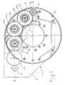
figure 1 shows a front partial section view of the driving system according to the invention, in accordance with a first embodiment thereof, made transversally to the rotational axis of the table; -
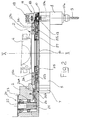
figure 2 shows a section view of the tool holder table and of the driving system made along the line II-I offigure 1 ; -
figure 3 shows an enlarged section view of a part offigure 2 ; -
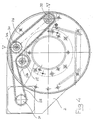
figure 4 shows a front partial section view of the driving system according to the invention in an alternative embodiment thereof, made transversally to the rotational axis of the table; -
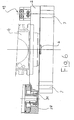
figure 5 shows a section view of the tool holder table and of the driving system made along the line V-V offigure 4 ; -
figure 6 shows a partial section view of the table and of the driving system offigure 5 . - With reference to the aforementioned figures, a tool holder table has been wholly indicated with 1, in particular a table for holding rotary drilling and boring tools.
- The stationary part of the table consists of a
body 2 equipped with a cavity 3 which extends around a longitudinal axis X-X; thebody 2 is intended to be connected to thefixed part 4 of a conventional turret partially indicated in the drawings. - The rotatable part of the table, is instead indicated with 5; it is connected to the rotatable part of the turret, represented by the shaft 6, the axis of which coincides with the axis X-X about which the angular displacements for changing the working station of the tools take place in a conventional manner.
- On the
rotatable part 5, in a circumferential zone,housings 7 for thespindles 8 are formed in which the rotary tools like the one indicated with 9 in the drawings are fixed. - Of these
conventional spindles 8, the tang of their respectivemotion receiving shaft 10a has been indicated with 10. - Then
stationary body 2 is equipped with an activation station of the tools wholly indicated with 11 in which asleeve 12 which is grooved on its inner surface is mounted. - Said
sleeve 12 is mounted so that it can slide axially inside abush 13 to which it is connected for rotation through a grooved coupling indicated with 14. - The
bush 13 which makes up the drive shaft of thespindles 8 is equipped, on the outside, with acoaxial sprocket 15 integral with it. - The
sleeve 12 is axially enveloped on theend 16 of apiston member 17 with the interposition ofbearings 18. - The
piston member 17, actuated in a conventional manner by a hydraulic system schematically indicated with 19, determines, upon command, the displacement of thesleeve 12 to ensure that it engages with thetang 10 of themotion receiving shaft 10a when thetool 9, at a given moment being in front of theactivation station 11, needs to be made to rotate. - Vice-versa, at the end of a machining operation, the
piston member 17, moving backwards, determines the detachment of thesleeve 12 from thetang 10. Following this the table 5 can be angularly displaced so that anotherspindle 8 with adifferent tool 9 is brought before theactivation station 11. - For their coupling and detachment, both the
motion receiving shaft 10a of each tool holder and thesleeve 12 have respective axes, not just parallel to the rotational axis X-X of the table 5 and thus of the turret in general, but also positioned on the respective supports so as to be axially aligned with each other when they are opposite one another and the turret is locked in the machining position. - The
body 2 comprises amotor housing 20 in which apinion 21 is housed with a hollowaxial part 22 intended for receiving the shaft of a non-illustrated electric motor in a conventional manner. - The
pinion 21 is supported by abearing 23 and interlocks with the toothing of agear 24 which constitutes the first element of a series of kinematic members for transferring the rotational motion from thepinion 21 to thebush 13, which constitutes the drive shaft, so as to be able to transfer it from this to thetool 9 mounted on the spindle. - The kinematic chain which constitutes the driving system for the present invention, in a first embodiment thereof, moreover comprises the
gears - The
gear 27 is, in turn, engaged with thesprocket 15 of thebush 13 of theactivation station 11 for the tools. - All of the sprockets made up of the
gears stationary body 2 of the tool holder table and are supported byrespective bearings respective screws side wall 2a of thebody 2 with a substantially coplanar arrangement. - Such a coplanar arrangement allows the cavity 3 of the
body 2 to be kept very flat thus allowing a somewhat reduced axial size of the tool holder table to be obtained. - In accordance with the embodiment illustrated in
figures 4 ,5 and6 , it should be noted that the series ofgears toothed belt 28 and thetransmission sprockets wall 2a of thebody 2 through the bearings 29a, 30a, andrespective screws - The arrangement of the
sprockets belt 28 which connects them is substantially coplanar with the same advantage of a reduction in the axial size already indicated in reference to the embodiment described previously. - In accordance with the embodiment of
figures 4 ,5 and6 , the pinion of the motor housing is replaced by awheel 31 with a toothing for a belt and thus also the gear of the activation station of the tools integral with thebush 13, is replaced with a sprocket for a toothed belt. - From that which has been described and illustrated in the drawings it can be noted that, in both embodiments of the driving system according to the invention, some of the intermediate kinematic members for the transmission of motion have their rotational axis positioned at a predetermined radial distance from the centre of rotation of the table 5 which is sufficient so that the kinematic chain of the transmission of motion does not cross the rotational axis X-X.
- Moreover, it is clear that, once the spindle with the desired
tool 9 is positioned opposite theactivation station 11 of the rotation of the tool, through a conventional angular displacement operation of the turret and therefore of therotatable part 5 of the table, the rotational motion is transferred to the spindle and from here to thetool 9 through a kinematic chain consisting of members of a smaller size which do not require special machining operations, which are supported in their operative functions through support members consisting of conventional bearings, which are also therefore not very expensive, providing a technical solution which is cost-effective and at the same time highly precise and reliable.
Claims (4)
- Driving system for rotary tools, in tool holder turrets for lathes, machining centres and the like, of the type comprising a stationary base body (2) with a cavity (3) which extends around a longitudinal axis (X-X), a tool holder table (5) which is rotatable with respect to the stationary base body (2) about a rotational axis coaxial and coinciding with the longitudinal axis (X-X) of said cavity (3), a plurality of tool housings (7) formed on said table (5) and distributed along a circumferential zone of the table, each of said housings (7) being equipped with a respective spindle (8) for holding a rotary tool (9) comprising a motion receiving shaft (10a) arranged parallel to said rotational axis (X-X) of the table, a drive shaft (13) for the rotation of the tools rotatably mounted on said stationary base body (2) with its rotational axis also parallel to said rotational axis (X-X) of the table, motor members (6) for angularly displacing the table (5) about said rotational axis (X-X) to take the motion receiving shaft (10a) of one of any of said tool holder spindles (8) in axial alignment with said drive shaft (13), means (12) capable of being displaced upon command, housed on said stationary body (2), for coupling and decoupling said drive shaft (13) with the motion receiving shaft (10a) of the tool holder spindle which, following the rotation of the table, is aligned with it, driving means (20, 21), mounted on said stationary base body (2) to force into rotation said drive shaft (13) for rotating the tools, said driving means comprising a drive shaft (21) with its axis parallel to the rotational axis (X-X) of the table (5) and motion transmission kinematic members (24, 25, 26, 27, 28, 29, 30, 31, 32), interposed between said shaft (21) of the driving means and said drive shaft for the tools (13), positioned on the same plane, said plane being transversal to the rotational axis (X-X) of the table (5), the rotational axes of said kinematic members being parallel to said rotational axis of the table, and characterised in that the rotational axes of all the motion transmission kinematic members are positioned at a predetermined radial distance from the centre of rotation of the rotatable table (5) which is sufficient so that the motion transmission kinematic chain does not cross the rotational axis X-X.
- Driving system according to claim 1 characterised in that said motion transmission kinematic members comprise a plurality of sprockets (24, 25, 26, 27), engaged with each other in correspondence with their toothed outer parts.
- Driving system according to claim 1 characterised in that said motion transmission kinematic members comprise wheels (29, 30, 31, 32) connected to each other through a belt (28).
- Driving means according to claim 3, characterised in that said wheels (29, 30, 31, 32) and said belt (28) are of the toothed type.
Applications Claiming Priority (1)
| Application Number | Priority Date | Filing Date | Title |
|---|---|---|---|
| PCT/IT2002/000219 WO2003084714A1 (en) | 2002-04-08 | 2002-04-08 | Driving system for rotary tools in a tool holder turret |
Publications (2)
| Publication Number | Publication Date |
|---|---|
| EP1492644A1 EP1492644A1 (en) | 2005-01-05 |
| EP1492644B1 true EP1492644B1 (en) | 2009-11-11 |
Family
ID=28687139
Family Applications (1)
| Application Number | Title | Priority Date | Filing Date |
|---|---|---|---|
| EP02728031A Expired - Lifetime EP1492644B1 (en) | 2002-04-08 | 2002-04-08 | Driving system for rotary tools in a tool holder turret |
Country Status (6)
| Country | Link |
|---|---|
| EP (1) | EP1492644B1 (en) |
| CN (1) | CN100544887C (en) |
| AU (1) | AU2002258159A1 (en) |
| DE (1) | DE60234387D1 (en) |
| TW (1) | TW200305478A (en) |
| WO (1) | WO2003084714A1 (en) |
Families Citing this family (2)
| Publication number | Priority date | Publication date | Assignee | Title |
|---|---|---|---|---|
| CN101264580B (en) * | 2007-03-13 | 2011-10-12 | 迪普马自动化公开有限公司 | Knife rack rotary tower |
| CN104793569B (en) * | 2015-04-07 | 2018-11-30 | 江南大学 | It is straight to drive numerical control turret intelligent controller |
Family Cites Families (5)
| Publication number | Priority date | Publication date | Assignee | Title |
|---|---|---|---|---|
| DE3305845C2 (en) * | 1983-02-19 | 1986-10-30 | Sauter Feinmechanik GmbH, 7430 Metzingen | Turret head for a machine tool, in particular a lathe |
| IT1185915B (en) * | 1985-09-13 | 1987-11-18 | Duplomatic Spa | REVOLVER TOOL HOLDER TURRET, ESPECIALLY FOR TURNING MACHINING CENTERS |
| DE8710865U1 (en) * | 1987-08-08 | 1987-09-24 | Sauter Feinmechanik GmbH, 7430 Metzingen | Tool turrets for machine tools |
| US4949443A (en) * | 1988-06-29 | 1990-08-21 | Tatsuhiko Saruwatari | Numerically controlled lathe |
| IT1240021B (en) * | 1990-04-30 | 1993-11-27 | Baruffaldi Spa | ENGAGEMENT DEVICE FOR TRANSMISSION OF THE MOTORCYCLE TO TOOL HOLDERS OF AUTOMATIC TURRETS |
-
2002
- 2002-04-08 WO PCT/IT2002/000219 patent/WO2003084714A1/en not_active Ceased
- 2002-04-08 CN CN02828538.7A patent/CN100544887C/en not_active Expired - Fee Related
- 2002-04-08 DE DE60234387T patent/DE60234387D1/en not_active Expired - Lifetime
- 2002-04-08 EP EP02728031A patent/EP1492644B1/en not_active Expired - Lifetime
- 2002-04-08 AU AU2002258159A patent/AU2002258159A1/en not_active Abandoned
-
2003
- 2003-04-08 TW TW092107952A patent/TW200305478A/en unknown
Also Published As
| Publication number | Publication date |
|---|---|
| WO2003084714A1 (en) | 2003-10-16 |
| EP1492644A1 (en) | 2005-01-05 |
| CN1622868A (en) | 2005-06-01 |
| TW200305478A (en) | 2003-11-01 |
| AU2002258159A1 (en) | 2003-10-20 |
| DE60234387D1 (en) | 2009-12-24 |
| CN100544887C (en) | 2009-09-30 |
Similar Documents
| Publication | Publication Date | Title |
|---|---|---|
| CN105473280B (en) | Rotary tables for machine tools | |
| EP2554301B1 (en) | Spindle device of a machine tool | |
| EP4204183B1 (en) | Machine tool | |
| US20100183395A1 (en) | Orbital drilling tool unit | |
| US4607549A (en) | Exchangeable turning head, particularly a face turning head | |
| US4638550A (en) | Horizontal drilling and milling machine | |
| US4635329A (en) | Tool holder assembly for machine tools | |
| US3978565A (en) | Multiple-spindle machine tool | |
| US4612690A (en) | Multiple spindle machine tool | |
| JP3816878B2 (en) | Multi spindle rotating machine | |
| EP0294869B1 (en) | Machine tool for turning, milling, boring, drilling and washing with independent means for clamping the part to be machined | |
| US5282300A (en) | Bar turning lathe with fixed poppet and retaking spindle | |
| CN113145880A (en) | Axial cutter bar and radial cutter bar composite multi-station turret type power cutter rest | |
| US5924344A (en) | Lathe | |
| US5016334A (en) | Multiple spindle bar machine | |
| EP0215748B1 (en) | A revolving turret particularly for lathe machining centers | |
| US5176052A (en) | Multi spindle automatic lathe | |
| EP1492644A1 (en) | Driving system for rotary tools in a tool holder turret | |
| JP4256098B2 (en) | 2-spindle facing lathe | |
| JPH02274403A (en) | Tool transfer-slide member for lathe | |
| JPH0436804B2 (en) | ||
| US4700594A (en) | Multi-spindle automatic lathe | |
| CN110605409A (en) | Machining center spindle and machining center | |
| US2691205A (en) | Auxiliary device for lathes | |
| US4528876A (en) | Universal single spindle pin crankshaft lathe |
Legal Events
| Date | Code | Title | Description |
|---|---|---|---|
| PUAI | Public reference made under article 153(3) epc to a published international application that has entered the european phase |
Free format text: ORIGINAL CODE: 0009012 |
|
| 17P | Request for examination filed |
Effective date: 20040730 |
|
| AK | Designated contracting states |
Kind code of ref document: A1 Designated state(s): AT BE CH CY DE DK ES FI FR GB GR IE IT LI LU MC NL PT SE TR |
|
| AX | Request for extension of the european patent |
Extension state: AL LT LV MK RO SI |
|
| 17Q | First examination report despatched |
Effective date: 20070814 |
|
| RAP1 | Party data changed (applicant data changed or rights of an application transferred) |
Owner name: DUPLOMATIC OLEODINAMICA S.P.A. |
|
| RAP1 | Party data changed (applicant data changed or rights of an application transferred) |
Owner name: DUPLOMATIC AUTOMAZIONE S.P.A. |
|
| GRAP | Despatch of communication of intention to grant a patent |
Free format text: ORIGINAL CODE: EPIDOSNIGR1 |
|
| GRAS | Grant fee paid |
Free format text: ORIGINAL CODE: EPIDOSNIGR3 |
|
| GRAA | (expected) grant |
Free format text: ORIGINAL CODE: 0009210 |
|
| AK | Designated contracting states |
Kind code of ref document: B1 Designated state(s): DE ES FR GB IT |
|
| REG | Reference to a national code |
Ref country code: GB Ref legal event code: FG4D |
|
| REF | Corresponds to: |
Ref document number: 60234387 Country of ref document: DE Date of ref document: 20091224 Kind code of ref document: P |
|
| RAP2 | Party data changed (patent owner data changed or rights of a patent transferred) |
Owner name: DUPLOMATIC AUTOMATION S.R.L. |
|
| PG25 | Lapsed in a contracting state [announced via postgrant information from national office to epo] |
Ref country code: ES Free format text: LAPSE BECAUSE OF FAILURE TO SUBMIT A TRANSLATION OF THE DESCRIPTION OR TO PAY THE FEE WITHIN THE PRESCRIBED TIME-LIMIT Effective date: 20100222 |
|
| PLBE | No opposition filed within time limit |
Free format text: ORIGINAL CODE: 0009261 |
|
| STAA | Information on the status of an ep patent application or granted ep patent |
Free format text: STATUS: NO OPPOSITION FILED WITHIN TIME LIMIT |
|
| 26N | No opposition filed |
Effective date: 20100812 |
|
| GBPC | Gb: european patent ceased through non-payment of renewal fee |
Effective date: 20100408 |
|
| REG | Reference to a national code |
Ref country code: FR Ref legal event code: ST Effective date: 20101230 |
|
| PG25 | Lapsed in a contracting state [announced via postgrant information from national office to epo] |
Ref country code: GB Free format text: LAPSE BECAUSE OF NON-PAYMENT OF DUE FEES Effective date: 20100408 |
|
| PG25 | Lapsed in a contracting state [announced via postgrant information from national office to epo] |
Ref country code: FR Free format text: LAPSE BECAUSE OF NON-PAYMENT OF DUE FEES Effective date: 20100430 |
|
| PGFP | Annual fee paid to national office [announced via postgrant information from national office to epo] |
Ref country code: DE Payment date: 20180420 Year of fee payment: 17 |
|
| PGFP | Annual fee paid to national office [announced via postgrant information from national office to epo] |
Ref country code: IT Payment date: 20180427 Year of fee payment: 17 |
|
| REG | Reference to a national code |
Ref country code: DE Ref legal event code: R119 Ref document number: 60234387 Country of ref document: DE |
|
| PG25 | Lapsed in a contracting state [announced via postgrant information from national office to epo] |
Ref country code: DE Free format text: LAPSE BECAUSE OF NON-PAYMENT OF DUE FEES Effective date: 20191101 |
|
| PG25 | Lapsed in a contracting state [announced via postgrant information from national office to epo] |
Ref country code: IT Free format text: LAPSE BECAUSE OF NON-PAYMENT OF DUE FEES Effective date: 20190408 |