EP0455286A2 - Coupling device for the transmission of the movement to toolholder units of automatic turrets - Google Patents
Coupling device for the transmission of the movement to toolholder units of automatic turrets Download PDFInfo
- Publication number
- EP0455286A2 EP0455286A2 EP91200836A EP91200836A EP0455286A2 EP 0455286 A2 EP0455286 A2 EP 0455286A2 EP 91200836 A EP91200836 A EP 91200836A EP 91200836 A EP91200836 A EP 91200836A EP 0455286 A2 EP0455286 A2 EP 0455286A2
- Authority
- EP
- European Patent Office
- Prior art keywords
- movement
- coupling
- turret
- transmission
- disposed
- Prior art date
- Legal status (The legal status is an assumption and is not a legal conclusion. Google has not performed a legal analysis and makes no representation as to the accuracy of the status listed.)
- Granted
Links
Images


Classifications
-
- F—MECHANICAL ENGINEERING; LIGHTING; HEATING; WEAPONS; BLASTING
- F16—ENGINEERING ELEMENTS AND UNITS; GENERAL MEASURES FOR PRODUCING AND MAINTAINING EFFECTIVE FUNCTIONING OF MACHINES OR INSTALLATIONS; THERMAL INSULATION IN GENERAL
- F16D—COUPLINGS FOR TRANSMITTING ROTATION; CLUTCHES; BRAKES
- F16D11/00—Clutches in which the members have interengaging parts
- F16D11/14—Clutches in which the members have interengaging parts with clutching members movable only axially
-
- B—PERFORMING OPERATIONS; TRANSPORTING
- B23—MACHINE TOOLS; METAL-WORKING NOT OTHERWISE PROVIDED FOR
- B23B—TURNING; BORING
- B23B29/00—Holders for non-rotary cutting tools; Boring bars or boring heads; Accessories for tool holders
- B23B29/24—Tool holders for a plurality of cutting tools, e.g. turrets
- B23B29/32—Turrets adjustable by power drive, i.e. turret heads
- B23B29/323—Turrets with power operated angular positioning devices
-
- B—PERFORMING OPERATIONS; TRANSPORTING
- B23—MACHINE TOOLS; METAL-WORKING NOT OTHERWISE PROVIDED FOR
- B23Q—DETAILS, COMPONENTS, OR ACCESSORIES FOR MACHINE TOOLS, e.g. ARRANGEMENTS FOR COPYING OR CONTROLLING; MACHINE TOOLS IN GENERAL CHARACTERISED BY THE CONSTRUCTION OF PARTICULAR DETAILS OR COMPONENTS; COMBINATIONS OR ASSOCIATIONS OF METAL-WORKING MACHINES, NOT DIRECTED TO A PARTICULAR RESULT
- B23Q39/00—Metal-working machines incorporating a plurality of sub-assemblies, each capable of performing a metal-working operation
- B23Q39/02—Metal-working machines incorporating a plurality of sub-assemblies, each capable of performing a metal-working operation the sub-assemblies being capable of being brought to act at a single operating station
-
- B—PERFORMING OPERATIONS; TRANSPORTING
- B23—MACHINE TOOLS; METAL-WORKING NOT OTHERWISE PROVIDED FOR
- B23Q—DETAILS, COMPONENTS, OR ACCESSORIES FOR MACHINE TOOLS, e.g. ARRANGEMENTS FOR COPYING OR CONTROLLING; MACHINE TOOLS IN GENERAL CHARACTERISED BY THE CONSTRUCTION OF PARTICULAR DETAILS OR COMPONENTS; COMBINATIONS OR ASSOCIATIONS OF METAL-WORKING MACHINES, NOT DIRECTED TO A PARTICULAR RESULT
- B23Q5/00—Driving or feeding mechanisms; Control arrangements therefor
- B23Q5/02—Driving main working members
- B23Q5/04—Driving main working members rotary shafts, e.g. working-spindles
-
- B—PERFORMING OPERATIONS; TRANSPORTING
- B23—MACHINE TOOLS; METAL-WORKING NOT OTHERWISE PROVIDED FOR
- B23Q—DETAILS, COMPONENTS, OR ACCESSORIES FOR MACHINE TOOLS, e.g. ARRANGEMENTS FOR COPYING OR CONTROLLING; MACHINE TOOLS IN GENERAL CHARACTERISED BY THE CONSTRUCTION OF PARTICULAR DETAILS OR COMPONENTS; COMBINATIONS OR ASSOCIATIONS OF METAL-WORKING MACHINES, NOT DIRECTED TO A PARTICULAR RESULT
- B23Q2220/00—Machine tool components
- B23Q2220/002—Tool turrets
Definitions
- the subject of the present invention is a coupling device for the transmission of the movement to rotatable toolholder units mounted on automatic turrets.
- the machining operations for a large number of workpieces require the use in succession,in accordance with a preprogrammed and automatically controlled cycle, of several tools on the same workpiece.
- the workpiece is usually mounted, for example, on a lathe which possesses a turret carrying several tools, which may be disposed turn and turn about in the working position for carrying out the machining required of them on the workpiece, under the control of an electronic unit.
- a fundamental requirement which arises in such machining operations is the speed of performance, with reduction particularly of the dead times which intervene between the end of the work of one tool and the start of the work of the next, these dead times being necessary for allowing the turret to carry out all the movements required for bringing the new tool into the working position and only at that point transmitting the rotating motion to the tool.
- the turret must, in fact, unlock itself from the fried working position, revolve in the one or the other sense depending upon which is the shortest travel, until it brings the new tool into the working position, and must stop and return into the blocked condition.
- the technical problem therefore arises of creating a toolholder turret for automatic machines, equipped with means for actuating the axial blocking and unblocking unit and means for actuating and transmitting the movement to the tool, in such a manner as to make possible positioning in correspondence with the working position of all the toolholder units with which the revolving disc is equipped and in such a way as to keep in rotation only the toolholder unit brought into correspondence with the sole working position, keeping all the others disengaged and stopped.
- the toolholder turret must furthermore make it possible to prevent any mistiming operation between toolholder unit revolving in the working position and actuating means for such unit, guaranteeing that the gearing and transmission of the movement to the tool takes place only with the turret positioned and blocked, and furthermore reducing the dead times relating to the unblocking, positioning, and renewed blocking of the turret and actuation of the tool in the working position.
- the turret must, furthermore, be constructed with the smallest possible number of components in order to achieve minimum wear and maximum life, in this way reducing the maintenance requirements.
- a coupling device for the transmission of the movement to rotatable toolholder units mounted on automatic turrets which comprises coupling means disposed in correspondence with the sole working position of the tool and adapted for executing axial translatory movement for engagement with the rotatable toolholder unit, under the action of actuating means for the translatory movement and control means for the axial blocking of the turret, said coupling means being furthermore adapted for revolving about their own axis under the action of means for generating and transmitting the movement, independently of the means for positioning the turret, in this way causing the coupling of the transmission of the movement to the sole tool disposed in the working position, with the turret blocked and with the axes of rotation of the toolholder unit and of the coupling means coinciding in a position of alignment;
- said coupling means are constituted of a coupling slider, axially disposed inside a gear wheel for receiving the movement from said generation and transmission means, which slider possesses a front
- said means for actuating the axial translation of the coupling slider shall comprise means for converting, into a rectilinear motion, a rotational motion generated by the annular body for controlling the blocking and unblocking of the turret, said motion conversion taking place in an elastic manner at the end of the blocking travel and at the start of the unblocking travel of the turret;
- said annular body possesses a cam for actuation in the two senses, arranged circumferentially and adapted for engaging, under the effect of the rotation of the annular body, with said means for converting the rotary motion into rectilinear motion, said body carrying, furthermore, several rollers having radial axes and being equipped with means for limiting the angular range, comprising a pin and a circumferential slot associated therewith, which slot is extended angularly on opposite sides of a median position, in correspondence with which the pin is situated.
- said means for converting the rotary motion into rectilinear motion preferably comprise an element movable in a linear direction, the ends of which are engaged, respectively, with the cam of the annular body and with a lever or the like acting, via elastic means, on a linear gear adapted for bringing into rotation a circular gear coaxial with the coupling slider, on which there are formed a plurality of inclined planes, interacting with thrust elements, associated with them and slidable on them, these thrust elements in turn disposed in engagement with said coupling element in such a manner as to convert the rotation of the circular gear into a push or return action of the coupling slider;
- said inclined planes and thrust means are composed of inclined slits and pins disposed inside them and acting linearly on the coupling slider, which slider, under the thrust action or pulling action of said pins, engages into or disengages from the movement pick-up gear of a rotatable toolholder unit.
- the elastic means of the linear gear are composed of a first, axially preloaded elastic means disposed between two parts of the linear gear itself, slidable axially relative to each other, and a second elastic means interposed between the linear gear and the fixed part of the turret, said first elastic means being capable of absorbing the coupling thrust if the coupling components should be opposite each other, and said second elastic means actuating the return into the disengagement position of the slider.
- the turret according to this invention is composed of an external support body 1, comprising a fixed ring 2, equipped with the fixed frontal set of teeth 3.
- a disc 4 Inside the body 1 is rotatably mounted a disc 4, to which can be connected the toolholder plate of the turret, not illustrated here; the disc 4 possesses the frontal set of teeth 5, concentric with and adjacent to the set of teeth 3.
- the front end 9 of a shaft 6, rotatable inside the body 1, is connected to the disc 4 by means of screws or the like 6a.
- a blocking ring 7 toothed at the front with a set of teeth 8, facing the sets of teeth 3, 5, and adapted for engaging with them, locking them to each other; between the widened-out front end 9 of the shaft 6 and the ring 7, there is situated a spring 10, with associated thrust bearing 11, acting in the direction for keeping the set of teeth 8 out of engagement with the sets of teeth 3, 5.
- a drive motor 12 which carries a pinion 13 in engagement with a toothed ring 14, which is secured, by means of pins or the like 15a, to a spider 15, carrying a plurality of planet wheel gears 16 disposed around a circumference, only one of which is illustrated in Fig. 1.
- the spider 15 is rotatably mounted, by bearings 17, around the cylindrical portion of a gear wheel 18, rotationally locked by means of keys 6b to the shaft 6 and engaging with its set of teeth 18a the planet wheel gears 16.
- the planet wheel gears 16 are, furthermore, in engagement with the set of teeth 19 of an annular body 20, coaxial with the shaft 6 and rotatable relative to same.
- the planet wheel gears 16, carried by the spider 15, constitute, in conjunction with the teeth 18a of the gear wheel 18 and the teeth 19 of the annular body 20, a differential unit of the epicyclic type, in which the rotational movement imparted to the spider 15 can be transmitted to the one or the other of the sets of teeth 18a, 19, when one of them is held blocked in rotation.
- the annular body 20 is equipped with a plurality of rollers 21, mounted on associated small shafts 22 having their axes radial relative to the shaft 6, these rollers bearing against the frontal cam profile 23 of the blocking ring 7.
- the blocking ring 7 is held with its frontal cam profile 23 pressed against the rollers 21 by the thrust exerted by the spring 10.
- the annular body 20 bears axially against the gear wheel 18, with the interposition of a thrust bearing 24, and the gear wheel 18 in turn bears against the stop ring 25, secured to the shaft 6 by a threaded zone 25a, with the interposition of a stack of cup springs 26.
- the annular body 20 possesses a plurality of equidistant frontal rollers 21; it is also provided with a circumferential recess 34 on its outer surface, having a limited angular extension, into which engages a fixed stop pin 35.
- a magnetic proximity sensor 36 or similar detection device adapted for detecting a projection 36a situated in correspondence with the desired stop position for the body 20.
- a pair of cams 20a adapted for engaging, as a result of the rotation of the body 20, with a thrust mechanism composed of a pin 41 equipped with a roller 41a in its end for contact with the cam 20a.
- the pin acts upon a drive arm 42a of a lever 42, pivoted at the centre, and the resistance arm 42b of which acts upon a toothed rack 43 by means of a preloaded spring 44 inserted into an inverted "U"-seating 45, of which the arms 45b partly contain said rack and bear against a further return spring 46.
- the rack 45 acts upon a circular thrust gear wheel 47, housed in a fixed circular seating 47a, on which seating there are formed three inclined slits 47b, into each of which there is inserted a pin 48, integral with the gear wheel 47 which, sliding along the inclined plane of the slit, is adapted for converting the circular motion of the gear wheel 47 into a linear push action onto a coupling element for transmission of the movement to the tool.
- the turret As illustrated in Figures 1, 4 and 5, the turret according to this invention carries a toolholder disc 49, secured to the movable ring 4 by screw fixing means 49a, which revolves about the axis of the shaft 6, while the motion for the tool is generated by an external motor 50, secured to the fixed ring 2, the shaft 50a of which is keyed to a pinion 51, which actuates, successively, a transmission gear wheel 51a, a toothed ring 52 and a second transmission wheel 53, which actuates a movement take-off pinion 54 for the tool.
- the latter pinion 54 has, inside it, an axial cavity with radial grooves, adapted for engaging with a corresponding set of teeth formed on a coupling slider 55, housed inside said cavity and slidable axially in it.
- Said slider 55 has, furthermore, a front ring of axial teeth (crown gear) 56, disposed on its front end for transmitting the motion to the toolholder spindle 57.
- the power input to the tool in turn is composed of a spindle 57, equipped at its rear end with a frontal ring of axial teeth (crown gear) 58, adapted for engaging with the corresponding ring 56 of the slider.
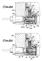
- the method of functioning of the turret is as follows: in operating conditions ( Figures 2a, 3a, 6a) the annular body 20 is disposed with the cam 20a thrusting on the pin 41, the toothed rack 43 lowered, the thrust pins 48 advanced, the coupling slider 55 advanced and the crown gears 56 and 58 of slider 55 and spindle 57 respectively engaged with each other; in this manner the tool, positioned at that instant in correspondence with the working position, takes the motion from the external motor 50 and is set in rotation.
- the toolholder turret for automatic machines makes possible the positioning in correspondence with the working position of all the toolholder units with which the rotating disc is equipped, and keeps in rotation only that toolholder unit which is disposed in correspondence with the sole working position, keeping all the others disengaged and stopped; making possible also the avoidance of any mistiming operation between the revolving toolholder unit in the working position and actuating means for this unit and also reducing the dead times related to unblocking, positioning, renewed blocking of the turret and actuation of the tool in the working position.
Landscapes
- Engineering & Computer Science (AREA)
- Mechanical Engineering (AREA)
- General Engineering & Computer Science (AREA)
- Cutting Tools, Boring Holders, And Turrets (AREA)
- Automatic Tool Replacement In Machine Tools (AREA)
Abstract
Description
- The subject of the present invention is a coupling device for the transmission of the movement to rotatable toolholder units mounted on automatic turrets. The machining operations for a large number of workpieces require the use in succession,in accordance with a preprogrammed and automatically controlled cycle, of several tools on the same workpiece. For this purpose, the workpiece is usually mounted, for example, on a lathe which possesses a turret carrying several tools, which may be disposed turn and turn about in the working position for carrying out the machining required of them on the workpiece, under the control of an electronic unit. A fundamental requirement which arises in such machining operations is the speed of performance, with reduction particularly of the dead times which intervene between the end of the work of one tool and the start of the work of the next, these dead times being necessary for allowing the turret to carry out all the movements required for bringing the new tool into the working position and only at that point transmitting the rotating motion to the tool. For this purpose, the turret must, in fact, unlock itself from the fried working position, revolve in the one or the other sense depending upon which is the shortest travel, until it brings the new tool into the working position, and must stop and return into the blocked condition. It is, therefore, of fundamental importance, with the objective of preventing impacts and fracture of the transmission members, that said transmission of the movement shall take place with the certainty that the turret shall be correctly positioned and blocked. Said operations are carried out, in the known turrets, by mechanical devices, which transmit the rotation from an actuating motor to the toolholder plate for the positioning, and from an external motor which at the same time actuates the blocking and unblocking means, with especially complicated constructions.
- The present applicant, in its earlier patent application IT-48,062 A/88, has described a toolholder turret in which the necessary unblocking, rotational and blocking movements of the turret are actuated by means of a single motor, which acts on a movable ring integral with the turret and with the actuating shaft, by means of a differential unit of the epicyclic type which acts on an annular body, the rotation of which causes a blocking ring for the movable ring to move in an axial direction, blocking in position being actuated by blocking elements which are radially movable and act upon a further body, integral with the actuating shaft, disposed between the axial blocking ring and the movable ring.
- This arrangement, nevertheless, does possess certain disadvantages, since because of the size required for the transmission elements and for transmission of the rotational motion from the shaft axis of the external motor to the axes of the individual tools, it is not possible to bring all the toolholder units available into correspondence with the working position.
- Furthermore, with the known arrangements, all the transmission units for the movement to the available tools are continually kept in rotation, causing wear and increasing energy consumption. A further disadvantage of the known forms of construction is represented by the fact that the positioning of the tool in correspondence with the working position and its engagement with the drive shaft for the tool take place in successive times, giving rise to dead times which reduce the productivity of the machine.
- The technical problem therefore arises of creating a toolholder turret for automatic machines, equipped with means for actuating the axial blocking and unblocking unit and means for actuating and transmitting the movement to the tool, in such a manner as to make possible positioning in correspondence with the working position of all the toolholder units with which the revolving disc is equipped and in such a way as to keep in rotation only the toolholder unit brought into correspondence with the sole working position, keeping all the others disengaged and stopped. The toolholder turret must furthermore make it possible to prevent any mistiming operation between toolholder unit revolving in the working position and actuating means for such unit, guaranteeing that the gearing and transmission of the movement to the tool takes place only with the turret positioned and blocked, and furthermore reducing the dead times relating to the unblocking, positioning, and renewed blocking of the turret and actuation of the tool in the working position. The turret must, furthermore, be constructed with the smallest possible number of components in order to achieve minimum wear and maximum life, in this way reducing the maintenance requirements.
- Said technical problems are resolved by a coupling device for the transmission of the movement to rotatable toolholder units mounted on automatic turrets, which comprises coupling means disposed in correspondence with the sole working position of the tool and adapted for executing axial translatory movement for engagement with the rotatable toolholder unit, under the action of actuating means for the translatory movement and control means for the axial blocking of the turret, said coupling means being furthermore adapted for revolving about their own axis under the action of means for generating and transmitting the movement, independently of the means for positioning the turret, in this way causing the coupling of the transmission of the movement to the sole tool disposed in the working position, with the turret blocked and with the axes of rotation of the toolholder unit and of the coupling means coinciding in a position of alignment; more specifically, said coupling means are constituted of a coupling slider, axially disposed inside a gear wheel for receiving the movement from said generation and transmission means, which slider possesses a front ring having axial teeth (crown gear) for engagement with a corresponding ring disposed on the rotatable toolholder unit and an axial grooved profile on its outer surface for engagement with a corresponding grooved profile disposed on the internal surface of said gear wheel. In the coupling device according to this invention, it is provided that said means for actuating the axial translation of the coupling slider shall comprise means for converting, into a rectilinear motion, a rotational motion generated by the annular body for controlling the blocking and unblocking of the turret, said motion conversion taking place in an elastic manner at the end of the blocking travel and at the start of the unblocking travel of the turret; preferably, said annular body possesses a cam for actuation in the two senses, arranged circumferentially and adapted for engaging, under the effect of the rotation of the annular body, with said means for converting the rotary motion into rectilinear motion, said body carrying, furthermore, several rollers having radial axes and being equipped with means for limiting the angular range, comprising a pin and a circumferential slot associated therewith, which slot is extended angularly on opposite sides of a median position, in correspondence with which the pin is situated.
- It is also provided that said means for converting the rotary motion into rectilinear motion preferably comprise an element movable in a linear direction, the ends of which are engaged, respectively, with the cam of the annular body and with a lever or the like acting, via elastic means, on a linear gear adapted for bringing into rotation a circular gear coaxial with the coupling slider, on which there are formed a plurality of inclined planes, interacting with thrust elements, associated with them and slidable on them, these thrust elements in turn disposed in engagement with said coupling element in such a manner as to convert the rotation of the circular gear into a push or return action of the coupling slider; preferably, said inclined planes and thrust means are composed of inclined slits and pins disposed inside them and acting linearly on the coupling slider, which slider, under the thrust action or pulling action of said pins, engages into or disengages from the movement pick-up gear of a rotatable toolholder unit. In the coupling device according to this invention, the elastic means of the linear gear are composed of a first, axially preloaded elastic means disposed between two parts of the linear gear itself, slidable axially relative to each other, and a second elastic means interposed between the linear gear and the fixed part of the turret, said first elastic means being capable of absorbing the coupling thrust if the coupling components should be opposite each other, and said second elastic means actuating the return into the disengagement position of the slider.
- Further details will be better understood from the following description of an example of embodiment of a coupling device according to the present invention, prepared in relation to the attached sheet of drawings, in which there are illustrated:
- in Fig. 1:
- a turret according to this invention, in axial section;
- in Fig. 2a:
- the turret blocked, in section on the plane II-II of Fig. 1;
- in Fig. 2b:
- the turret in section on the plane II-II of Fig. 1, but in the unblocked conditions for a tool change;
- in Fig. 3a:
- a detail of the coupling mechanism in section on the plane IIIA-IIIA of Fig. 2a;
- in Fig. 3b:
- a detail of the push mechanism in section on the plane IIIB-IIIB of Fig. 2b;
- in Fig. 4:
- a schematic front view of the turret;
- in Fig. 5:
- a partial section through the turret on the plane V-V of Fig. 4;
- in Fig. 6a:
- an enlarged detail in partial section of the working position with turret closed and tool engaged in rotation;
- in Fig. 6b:
- a detail of Fig. 6a, but with the turret open for changing tools.
- With reference to Fig. 1, the turret according to this invention is composed of an external support body 1, comprising a
fixed ring 2, equipped with the fixed frontal set of teeth 3. - Inside the body 1 is rotatably mounted a disc 4, to which can be connected the toolholder plate of the turret, not illustrated here; the disc 4 possesses the frontal set of
teeth 5, concentric with and adjacent to the set of teeth 3. Thefront end 9 of ashaft 6, rotatable inside the body 1, is connected to the disc 4 by means of screws or the like 6a. - Around the
shaft 6 there is present a blocking ring 7, toothed at the front with a set ofteeth 8, facing the sets ofteeth 3, 5, and adapted for engaging with them, locking them to each other; between the widened-outfront end 9 of theshaft 6 and the ring 7, there is situated aspring 10, with associated thrust bearing 11, acting in the direction for keeping the set ofteeth 8 out of engagement with the sets ofteeth 3, 5. - Inside the outer body 1 is mounted a
drive motor 12, which carries apinion 13 in engagement with atoothed ring 14, which is secured, by means of pins or the like 15a, to aspider 15, carrying a plurality ofplanet wheel gears 16 disposed around a circumference, only one of which is illustrated in Fig. 1. - The
spider 15 is rotatably mounted, by bearings 17, around the cylindrical portion of agear wheel 18, rotationally locked by means of keys 6b to theshaft 6 and engaging with its set ofteeth 18a theplanet wheel gears 16. - The
planet wheel gears 16 are, furthermore, in engagement with the set ofteeth 19 of anannular body 20, coaxial with theshaft 6 and rotatable relative to same. - The
planet wheel gears 16, carried by thespider 15, constitute, in conjunction with theteeth 18a of thegear wheel 18 and theteeth 19 of theannular body 20, a differential unit of the epicyclic type, in which the rotational movement imparted to thespider 15 can be transmitted to the one or the other of the sets ofteeth - The
annular body 20 is equipped with a plurality ofrollers 21, mounted on associatedsmall shafts 22 having their axes radial relative to theshaft 6, these rollers bearing against thefrontal cam profile 23 of the blocking ring 7. - The blocking ring 7 is held with its
frontal cam profile 23 pressed against therollers 21 by the thrust exerted by thespring 10. - The
annular body 20 bears axially against thegear wheel 18, with the interposition of a thrust bearing 24, and thegear wheel 18 in turn bears against thestop ring 25, secured to theshaft 6 by a threadedzone 25a, with the interposition of a stack ofcup springs 26. - As illustrated in Fig. 2a, the
annular body 20 possesses a plurality of equidistantfrontal rollers 21; it is also provided with acircumferential recess 34 on its outer surface, having a limited angular extension, into which engages afixed stop pin 35. - Facing the surface of the
body 20, there is also amagnetic proximity sensor 36 or similar detection device adapted for detecting aprojection 36a situated in correspondence with the desired stop position for thebody 20. - On the
annular body 20 there are also formed a pair ofcams 20a adapted for engaging, as a result of the rotation of thebody 20, with a thrust mechanism composed of apin 41 equipped with aroller 41a in its end for contact with thecam 20a. At the opposite end 41b the pin acts upon adrive arm 42a of alever 42, pivoted at the centre, and the resistance arm 42b of which acts upon atoothed rack 43 by means of a preloadedspring 44 inserted into an inverted "U"-seating 45, of which the arms 45b partly contain said rack and bear against afurther return spring 46. - The
rack 45, in turn, acts upon a circularthrust gear wheel 47, housed in a fixedcircular seating 47a, on which seating there are formed three inclined slits 47b, into each of which there is inserted apin 48, integral with thegear wheel 47 which, sliding along the inclined plane of the slit, is adapted for converting the circular motion of thegear wheel 47 into a linear push action onto a coupling element for transmission of the movement to the tool. - As illustrated in Figures 1, 4 and 5, the turret according to this invention carries a
toolholder disc 49, secured to the movable ring 4 by screw fixing means 49a, which revolves about the axis of theshaft 6, while the motion for the tool is generated by anexternal motor 50, secured to thefixed ring 2, theshaft 50a of which is keyed to apinion 51, which actuates, successively, atransmission gear wheel 51a, atoothed ring 52 and asecond transmission wheel 53, which actuates a movement take-offpinion 54 for the tool. Thelatter pinion 54 has, inside it, an axial cavity with radial grooves, adapted for engaging with a corresponding set of teeth formed on acoupling slider 55, housed inside said cavity and slidable axially in it. Saidslider 55 has, furthermore, a front ring of axial teeth (crown gear) 56, disposed on its front end for transmitting the motion to thetoolholder spindle 57. The power input to the tool in turn is composed of aspindle 57, equipped at its rear end with a frontal ring of axial teeth (crown gear) 58, adapted for engaging with the correspondingring 56 of the slider. The method of functioning of the turret is as follows: in operating conditions (Figures 2a, 3a, 6a) theannular body 20 is disposed with thecam 20a thrusting on thepin 41, thetoothed rack 43 lowered, the thrust pins 48 advanced, thecoupling slider 55 advanced and the crown gears 56 and 58 ofslider 55 andspindle 57 respectively engaged with each other; in this manner the tool, positioned at that instant in correspondence with the working position, takes the motion from theexternal motor 50 and is set in rotation. At the time of changing the tool (Figures 2b, 3b, 6b) theannular body 20 is caused to revolve until the fixedstop pin 35 comes into bearing against the end of therecess 34, and in this position, simultaneously with the axial sliding of the blocking ring 7 which releases the movable ring 4, it is found that thecam 20a disengages from thepin 41 which, sliding downwards, releases thelever 42, which by rotating upwards allows thetoothed rack 43 to return into the raised position under the action of the thrust exerted by thereturn spring 46. The translatory movement of thetoothed rack 43 causes thecircular gear wheel 47 to revolve which, by revolving, compels the thrust pins 48 to slide on the inclined plane of the slits 47b, thus returning into their more remote position and pulling with them thecoupling slider 55 for transmitting the movement to thespindle 57 of the toolholder. In these conditions, both the movable ring 4 and thetoolholder plate 49 connected to it are free to rotate under the action of theprincipal shaft 6, to carry out the positioning of a different tool in correspondence with the working position. - Once this positioning has been completed, a new rotation of the
annular body 20 again brings the various elements described to the initial position (Figures 2a, 3a, 6a) corresponding to the working conditions. Whenever the relative position of the various elements may allow an abutment position of the axial teeth, the load in theprestressed spring 44 would then allow the cycle of tool-changing and turret-blocking to be terminated, permitting a gradual engagement into the cavities which are present opposite the teeth as a result of the relative rotations of the individual elements and in this manner preventing abrupt coupling, which could cause breakages and the like. It is therefore evident from the above description how the toolholder turret for automatic machines according to the present invention makes possible the positioning in correspondence with the working position of all the toolholder units with which the rotating disc is equipped, and keeps in rotation only that toolholder unit which is disposed in correspondence with the sole working position, keeping all the others disengaged and stopped; making possible also the avoidance of any mistiming operation between the revolving toolholder unit in the working position and actuating means for this unit and also reducing the dead times related to unblocking, positioning, renewed blocking of the turret and actuation of the tool in the working position.
Claims (8)
- Coupling device for the transmission of the movement to rotatable toolholder units mounted on automatic turrets, characterized in that it comprises coupling means disposed in correspondence with the sole working position for the tool and adapted for performing an axial translatory movement for engagement with the rotatable toolholder unit (57), under the action of actuating means (47) for the translatory movement and control means (20) for the axial blocking of the turret, said coupling means being, furthermore, adapted for revolving around their own axis under the action of means for generating (50) and transmitting (51, 52, 53) the movement, independent of the means for positioning the turret, in this way causing coupling of the transmission of the movement to the sole tool disposed in the working position, with the turret blocked and with axes of rotation of the toolholder unit and of the coupling means coinciding with each other in a position of alignment.
- Coupling device for the transmission of the movement to toolholder units mounted on automatic turrets according to Claim 1, characterized in that said coupling means are constituted of a coupling slider (55), disposed axially inside a take-off pinion (54) for the movement from said generating (50) and transmission (51-53) means, which slider possesses a frontal ring of axial teeth (56) for engagement with a corresponding ring (58) disposed on the rotatable toolholder unit (57) and an axial grooved profile (55a) on its outer surface for engagement with a corresponding grooved profile (54a) disposed on the internal surface of said pinion (54).
- Coupling device for the transmission of the movement to toolholder units mounted on automatic turrets according to Claim 1, characterized in that said actuating means for the axial translatory movement of the coupling slider (55) comprise means for converting a rotational movement generated by the annular body (20) for controlling the blocking and unblocking of the turret into a rectilinear movement, said movement conversion taking place in an elastic manner at the end of the blocking travel and at the start of the unblocking travel of the turret.
- Coupling device for the transmission according to Claim 1, characterized in that said annular body (20) possesses a cam (20a) acting in both directions, disposed circumferentially, and adapted for engaging, under the effect of the rotation of the annular body, with said conversion means for the rotational into the rectilinear movement, said body (20) carrying, furthermore, a plurality of rollers (21) having radial axes and being equipped with means for limiting the angular range, comprising a pin (35) and a circumferential recess (34) associated with it, which recess extends angularly on opposite sides from a median position, in correspondence with which the pin (35) is situated.
- Coupling device for the transmission according to Claim 1, characterized in that said means for converting the rotational movement into rectilinear movement preferably comprise a linearly movable element (41) the ends of which are, respectively, engaged with the cam (20a) of the annular body (20) and with a lever (42) or the like, acting via elastic means (43, 44) on a linear gear (43) adapted for causing rotation of a circular gear (47), coaxial with the coupling slider (55), on which are formed a plurality of inclined planes interacting with thrust elements, associated with them and slidable on them, these thrust elements in turn being disposed in engagement with said coupling element (55) in such a manner as to convert the rotation of the circular gear (47) into a thrust action or return action of the coupling slider (55).
- Coupling device according to Claims 1 and 5, characterized in that said inclined planes and thrust means are preferably composed of inclined slits (47b) and pins (48) disposed inside them and acting linearly on the coupling slider (55), which under the pushing or pulling action of said pins engages with or disengages from the pick-up gear for the movement of a rotatable toolholder unit (57).
- Coupling device according to Claim 1, characterized in that said means for generating and transmitting the movement are preferably composed of a motor (50) which actuates a pinion (54) by means of a transmission composed of two gear wheels (51a, 53) and a ring (52).
- Coupling device according to Claim 1, characterized in that said elastic means for the linear gear (43) are composed of a first, axially prestressed elastic means (44), disposed between two parts of said linear gear and axially slidable between them and of a second elastic means (46) interposed between the linear gear and the fixed part of the turret, said first elastic means being capable of absorbing the coupling thrust when the coupling components are opposite each other and said second elastic means actuating the return into the disengagement position of the slider (55).
Applications Claiming Priority (2)
| Application Number | Priority Date | Filing Date | Title |
|---|---|---|---|
| IT20170A IT1240021B (en) | 1990-04-30 | 1990-04-30 | ENGAGEMENT DEVICE FOR TRANSMISSION OF THE MOTORCYCLE TO TOOL HOLDERS OF AUTOMATIC TURRETS |
| IT2017090 | 1990-04-30 |
Publications (3)
| Publication Number | Publication Date |
|---|---|
| EP0455286A2 true EP0455286A2 (en) | 1991-11-06 |
| EP0455286A3 EP0455286A3 (en) | 1992-06-10 |
| EP0455286B1 EP0455286B1 (en) | 1996-07-10 |
Family
ID=11164385
Family Applications (1)
| Application Number | Title | Priority Date | Filing Date |
|---|---|---|---|
| EP91200836A Expired - Lifetime EP0455286B1 (en) | 1990-04-30 | 1991-04-11 | Coupling device for the transmission of the movement to toolholder units of automatic turrets |
Country Status (5)
| Country | Link |
|---|---|
| EP (1) | EP0455286B1 (en) |
| JP (1) | JPH04226813A (en) |
| DE (1) | DE69120723T2 (en) |
| ES (1) | ES2090228T3 (en) |
| IT (1) | IT1240021B (en) |
Cited By (4)
| Publication number | Priority date | Publication date | Assignee | Title |
|---|---|---|---|---|
| WO2003084714A1 (en) * | 2002-04-08 | 2003-10-16 | Duplomatic Automazione S.P.A. | Driving system for rotary tools in a tool holder turret |
| US6640404B2 (en) * | 2000-08-28 | 2003-11-04 | Hardinge Inc. | Three piece coupling arrangement for a turret indexing mechanism for a machine tool assembly and an air bearing assembly for the same |
| WO2008084489A1 (en) * | 2007-01-08 | 2008-07-17 | Ashok Vishwanath Sathe | System of actuation of drive coupling to engage and disengage the drive to rotary tool holders |
| CN104895944A (en) * | 2015-05-12 | 2015-09-09 | 安徽省海安机械制造股份有限公司 | Multifunctional compound machine tool power switching device |
Families Citing this family (1)
| Publication number | Priority date | Publication date | Assignee | Title |
|---|---|---|---|---|
| JP3030093B2 (en) * | 1996-12-13 | 2000-04-10 | シチズン時計株式会社 | Indexing device and indexing driving method of the device |
Family Cites Families (6)
| Publication number | Priority date | Publication date | Assignee | Title |
|---|---|---|---|---|
| FR2030654A5 (en) * | 1969-11-20 | 1970-11-13 | Roux Jacques | |
| DE3134969C2 (en) * | 1981-09-04 | 1984-05-17 | Sauter Feinmechanik GmbH, 7430 Metzingen | Tool turret |
| GB2126134B (en) * | 1982-09-03 | 1986-01-08 | 600 Group P L C The | Common turret indexing and tool holder drive mechanism |
| DE3668565D1 (en) * | 1985-08-12 | 1990-03-08 | Schaeublin Sa | DEVICE FOR DRIVING TOOL CARRIERS IN A MACHINE TOOL. |
| DE3855228D1 (en) * | 1987-07-14 | 1996-05-30 | Baruffaldi Spa | Tool turret with an epicycloid gear and positioning unit |
| DE8710865U1 (en) * | 1987-08-08 | 1987-09-24 | Sauter Feinmechanik GmbH, 7430 Metzingen | Tool turrets for machine tools |
-
1990
- 1990-04-30 IT IT20170A patent/IT1240021B/en active IP Right Grant
-
1991
- 1991-04-11 EP EP91200836A patent/EP0455286B1/en not_active Expired - Lifetime
- 1991-04-11 DE DE69120723T patent/DE69120723T2/en not_active Expired - Fee Related
- 1991-04-11 ES ES91200836T patent/ES2090228T3/en not_active Expired - Lifetime
- 1991-04-25 JP JP3121880A patent/JPH04226813A/en active Pending
Cited By (5)
| Publication number | Priority date | Publication date | Assignee | Title |
|---|---|---|---|---|
| US6640404B2 (en) * | 2000-08-28 | 2003-11-04 | Hardinge Inc. | Three piece coupling arrangement for a turret indexing mechanism for a machine tool assembly and an air bearing assembly for the same |
| WO2003084714A1 (en) * | 2002-04-08 | 2003-10-16 | Duplomatic Automazione S.P.A. | Driving system for rotary tools in a tool holder turret |
| WO2008084489A1 (en) * | 2007-01-08 | 2008-07-17 | Ashok Vishwanath Sathe | System of actuation of drive coupling to engage and disengage the drive to rotary tool holders |
| CN104895944A (en) * | 2015-05-12 | 2015-09-09 | 安徽省海安机械制造股份有限公司 | Multifunctional compound machine tool power switching device |
| CN104895944B (en) * | 2015-05-12 | 2017-11-21 | 安徽省海安机械制造股份有限公司 | Multi-function peripheral bed switchover apparatus |
Also Published As
| Publication number | Publication date |
|---|---|
| IT9020170A1 (en) | 1991-10-30 |
| DE69120723T2 (en) | 1996-11-28 |
| EP0455286A3 (en) | 1992-06-10 |
| IT9020170A0 (en) | 1990-04-30 |
| IT1240021B (en) | 1993-11-27 |
| EP0455286B1 (en) | 1996-07-10 |
| DE69120723D1 (en) | 1996-08-14 |
| ES2090228T3 (en) | 1996-10-16 |
| JPH04226813A (en) | 1992-08-17 |
Similar Documents
| Publication | Publication Date | Title |
|---|---|---|
| EP0299556B1 (en) | Tool-holder turret with an epicyclic transmission and positioning unit | |
| US4748357A (en) | Electromechanical apparatus for producing an axial force for actuating clamping devices | |
| DK3003594T3 (en) | punching | |
| CN106926045B (en) | Tool holder turret with coaxial brake | |
| JP2524189B2 (en) | Turret rotary tool turret | |
| US4467680A (en) | Tool turret with revolving head | |
| EP0455286B1 (en) | Coupling device for the transmission of the movement to toolholder units of automatic turrets | |
| US4468991A (en) | Tool turret | |
| GB2275631A (en) | Tool turret | |
| GB2051299A (en) | Apparatus for coupling and uncoupling of a kinematic mechanism in which a stepwise rotary motion is imparted | |
| US2874595A (en) | Power turret indexing | |
| EP3677366B1 (en) | Turret tool post | |
| US3024520A (en) | Turret operating mechanism for automatic machine tools | |
| US5887500A (en) | Tool-carrying turret with stopping devices performing automatic centering of the means for locking the turret itself | |
| EP0661133B1 (en) | A machining unit with a series of selectively operable tool-carrier mandrels | |
| JP3247568B2 (en) | Turret head unit | |
| US4452093A (en) | Drive unit | |
| US2748451A (en) | Gear transmissions | |
| RU1787697C (en) | Turned head | |
| SU956167A1 (en) | Clamping chuck drive | |
| JPH088002Y2 (en) | Index head with slow rotation mechanism | |
| SU512033A1 (en) | Device for finishing raceways | |
| SU1763098A1 (en) | Turret | |
| CN121876157A (en) | Planetary gear train escapement buffer mechanism | |
| JPH07214447A (en) | Drive device and tool changer equipped with the drive device |
Legal Events
| Date | Code | Title | Description |
|---|---|---|---|
| PUAI | Public reference made under article 153(3) epc to a published international application that has entered the european phase |
Free format text: ORIGINAL CODE: 0009012 |
|
| AK | Designated contracting states |
Kind code of ref document: A2 Designated state(s): BE CH DE DK ES FR GB GR IT LI SE |
|
| PUAL | Search report despatched |
Free format text: ORIGINAL CODE: 0009013 |
|
| AK | Designated contracting states |
Kind code of ref document: A3 Designated state(s): BE CH DE DK ES FR GB GR IT LI SE |
|
| 17P | Request for examination filed |
Effective date: 19921128 |
|
| 17Q | First examination report despatched |
Effective date: 19940812 |
|
| GRAH | Despatch of communication of intention to grant a patent |
Free format text: ORIGINAL CODE: EPIDOS IGRA |
|
| GRAH | Despatch of communication of intention to grant a patent |
Free format text: ORIGINAL CODE: EPIDOS IGRA |
|
| GRAA | (expected) grant |
Free format text: ORIGINAL CODE: 0009210 |
|
| AK | Designated contracting states |
Kind code of ref document: B1 Designated state(s): BE CH DE DK ES FR GB GR IT LI SE |
|
| PG25 | Lapsed in a contracting state [announced via postgrant information from national office to epo] |
Ref country code: LI Effective date: 19960710 Ref country code: GR Free format text: LAPSE BECAUSE OF FAILURE TO SUBMIT A TRANSLATION OF THE DESCRIPTION OR TO PAY THE FEE WITHIN THE PRESCRIBED TIME-LIMIT Effective date: 19960710 Ref country code: DK Effective date: 19960710 Ref country code: CH Effective date: 19960710 Ref country code: BE Effective date: 19960710 |
|
| REF | Corresponds to: |
Ref document number: 69120723 Country of ref document: DE Date of ref document: 19960814 |
|
| ET | Fr: translation filed | ||
| ITF | It: translation for a ep patent filed | ||
| PG25 | Lapsed in a contracting state [announced via postgrant information from national office to epo] |
Ref country code: SE Effective date: 19961010 |
|
| REG | Reference to a national code |
Ref country code: ES Ref legal event code: FG2A Ref document number: 2090228 Country of ref document: ES Kind code of ref document: T3 |
|
| REG | Reference to a national code |
Ref country code: ES Ref legal event code: FG2A Ref document number: 2090228 Country of ref document: ES Kind code of ref document: T3 |
|
| REG | Reference to a national code |
Ref country code: CH Ref legal event code: PL |
|
| PGFP | Annual fee paid to national office [announced via postgrant information from national office to epo] |
Ref country code: GB Payment date: 19970404 Year of fee payment: 7 |
|
| PGFP | Annual fee paid to national office [announced via postgrant information from national office to epo] |
Ref country code: ES Payment date: 19970418 Year of fee payment: 7 |
|
| PGFP | Annual fee paid to national office [announced via postgrant information from national office to epo] |
Ref country code: FR Payment date: 19970422 Year of fee payment: 7 |
|
| PLBE | No opposition filed within time limit |
Free format text: ORIGINAL CODE: 0009261 |
|
| STAA | Information on the status of an ep patent application or granted ep patent |
Free format text: STATUS: NO OPPOSITION FILED WITHIN TIME LIMIT |
|
| 26N | No opposition filed | ||
| PG25 | Lapsed in a contracting state [announced via postgrant information from national office to epo] |
Ref country code: GB Free format text: LAPSE BECAUSE OF NON-PAYMENT OF DUE FEES Effective date: 19980411 |
|
| PG25 | Lapsed in a contracting state [announced via postgrant information from national office to epo] |
Ref country code: ES Free format text: LAPSE BECAUSE OF EXPIRATION OF PROTECTION Effective date: 19980413 |
|
| PG25 | Lapsed in a contracting state [announced via postgrant information from national office to epo] |
Ref country code: FR Free format text: THE PATENT HAS BEEN ANNULLED BY A DECISION OF A NATIONAL AUTHORITY Effective date: 19980430 |
|
| GBPC | Gb: european patent ceased through non-payment of renewal fee |
Effective date: 19980411 |
|
| REG | Reference to a national code |
Ref country code: FR Ref legal event code: ST |
|
| REG | Reference to a national code |
Ref country code: ES Ref legal event code: FD2A Effective date: 20000201 |
|
| PGFP | Annual fee paid to national office [announced via postgrant information from national office to epo] |
Ref country code: DE Payment date: 20030623 Year of fee payment: 13 |
|
| PG25 | Lapsed in a contracting state [announced via postgrant information from national office to epo] |
Ref country code: DE Free format text: LAPSE BECAUSE OF NON-PAYMENT OF DUE FEES Effective date: 20041103 |
|
| PG25 | Lapsed in a contracting state [announced via postgrant information from national office to epo] |
Ref country code: IT Free format text: LAPSE BECAUSE OF NON-PAYMENT OF DUE FEES;WARNING: LAPSES OF ITALIAN PATENTS WITH EFFECTIVE DATE BEFORE 2007 MAY HAVE OCCURRED AT ANY TIME BEFORE 2007. THE CORRECT EFFECTIVE DATE MAY BE DIFFERENT FROM THE ONE RECORDED. Effective date: 20050411 |