EP1491850A2 - Measuring instrument and method for determining the spatial orientation of a body relative to two horizontal reference directions - Google Patents
Measuring instrument and method for determining the spatial orientation of a body relative to two horizontal reference directions Download PDFInfo
- Publication number
- EP1491850A2 EP1491850A2 EP04003808A EP04003808A EP1491850A2 EP 1491850 A2 EP1491850 A2 EP 1491850A2 EP 04003808 A EP04003808 A EP 04003808A EP 04003808 A EP04003808 A EP 04003808A EP 1491850 A2 EP1491850 A2 EP 1491850A2
- Authority
- EP
- European Patent Office
- Prior art keywords
- directions
- measuring device
- inclinometers
- inclinometer
- individual
- Prior art date
- Legal status (The legal status is an assumption and is not a legal conclusion. Google has not performed a legal analysis and makes no representation as to the accuracy of the status listed.)
- Granted
Links
Images


Classifications
-
- G—PHYSICS
- G01—MEASURING; TESTING
- G01B—MEASURING LENGTH, THICKNESS OR SIMILAR LINEAR DIMENSIONS; MEASURING ANGLES; MEASURING AREAS; MEASURING IRREGULARITIES OF SURFACES OR CONTOURS
- G01B21/00—Measuring arrangements or details thereof, where the measuring technique is not covered by the other groups of this subclass, unspecified or not relevant
- G01B21/22—Measuring arrangements or details thereof, where the measuring technique is not covered by the other groups of this subclass, unspecified or not relevant for measuring angles or tapers; for testing the alignment of axes
- G01B21/24—Measuring arrangements or details thereof, where the measuring technique is not covered by the other groups of this subclass, unspecified or not relevant for measuring angles or tapers; for testing the alignment of axes for testing alignment of axes
-
- G—PHYSICS
- G01—MEASURING; TESTING
- G01C—MEASURING DISTANCES, LEVELS OR BEARINGS; SURVEYING; NAVIGATION; GYROSCOPIC INSTRUMENTS; PHOTOGRAMMETRY OR VIDEOGRAMMETRY
- G01C19/00—Gyroscopes; Turn-sensitive devices using vibrating masses; Turn-sensitive devices without moving masses; Measuring angular rate using gyroscopic effects
- G01C19/02—Rotary gyroscopes
- G01C19/04—Details
- G01C19/30—Erection devices, i.e. devices for restoring rotor axis to a desired position
-
- G—PHYSICS
- G01—MEASURING; TESTING
- G01C—MEASURING DISTANCES, LEVELS OR BEARINGS; SURVEYING; NAVIGATION; GYROSCOPIC INSTRUMENTS; PHOTOGRAMMETRY OR VIDEOGRAMMETRY
- G01C9/00—Measuring inclination, e.g. by clinometers, by levels
Definitions
- the invention relates to a measuring device for the precise determination of the spatial orientation of a body relative to two horizontal reference directions, so that the determination of both a pitch and a roll angle can be performed in an improved and very accurate manner.
- the body should be stored fixed space and immobile to perform the measurement, at least may (and must) during the execution of the measurement on the body only the gravitational act on this.
- the invention is not suitable for applications in weightlessness in space.
- the invention relates to at least one method for providing an overall measurement result from individual measurement results provided by inclinometer subsystems.
- the invention relates to the use of the measuring device for determining two components of the spatial orientation of machines or machine elements such as e.g. Rolling or rolling, as well as providing correction information to bring misaligned machines or machine elements into an aligned position, further including the use of the measuring device for directional determination on other objects.
- a specified in DE 42 05 869 method is still considerably more expensive, since a double set of gyro systems is provided for the measurement.
- the device is intended to be positioned by means of an adapter on the front ends of rollers can; It is additionally equipped with a laser-based position measuring device.
- the stated task is based on the invention described in the present application.
- the invention solves the problem at hand by providing a redundant design of a two-dimensional sensing direction measuring system equipped with inclinometers so that its functional properties are improved both in terms of operational reliability and, in particular, accuracy. At the same time, if less accurate and thus less expensive individual systems are used, the production costs of the entire system are reduced.
- the invention instead of an inclinometer system comprising two orthogonally oriented single inclinometers, the invention provides for such a system which consists of at least three, preferably four or further individual inclinometers. These are preferably MEMS inclinometers which individually can not indicate the direction of an acceleration (in contrast to simple liquid inclinometers according to FIGS.
- the solution of the underlying problem can be provided by implementing the following principle arrangement: Measuring device for determining the spatial orientation of a body relative to two reference directions lying in a horizontal plane in particular, with a housing for application to a surface or edge of a body to be measured, with a plurality of inclinometer systems for determining stable space positions or tilting systems.
- a computationally interesting embodiment of the invention consists, for example, of eight single linear meters arranged symmetrically about an axis or about a center. Regardless of whether they are low-cost or high-quality single inclinometers, disproportionately improved accuracies can be provided in any case by combining a large number of identical or differently constructed individual inclinometers, since it is sometimes possible to determine temperature and compensate for gravity effects by subtraction, averaging or other statistical considerations.
- a measuring device for determining the spatial orientation of a body relative to two reference directions lying in a horizontal plane comprising a housing for application to a surface of a body to be measured, within which a plurality of individual inclinometers for determining a proportional value the gravitational acceleration is provided with respect to respective axes of symmetry associated with the individual inclinometers, and wherein the measuring device is characterized in that at least three, but preferably four or many further, single inclinometers are provided within the housing, which are oriented as non-coplanar as possible in different spatial directions are aligned, and wherein all combinations of three non-coplanar oriented, to a so-called.
- Einzelinclinometer provide a first measurement result, which is the spatial angular Orientation of the measuring device or a body contacted with this according to the two spatial coordinates "roll" and "" Pitch identifies.
- This arrangement according to the invention is used so that initially a plurality of measurement results of the first kind is provided, and then from the plurality of measurement results of the first kind in addition a total measurement result (ie measurement result of the second kind) is determined, which in comparison to the individual measurement results of the first kind indicates a significantly more accurate angular orientation of the meter or a contacted with this body.
- a significantly more accurate measurement result can be immediately provided from the plurality of measurement results of the first type using a suitable mathematical algorithm such as SVD (singular matrix decomposition).
- the number of eight individual inclinometer systems within an overall system according to the invention is to be understood as an example only. It can also be four, five, six, etc.
- Inclinometer or a significantly larger number are used, for example, 150 to 400 miniaturized elements of this type, in particular those whose output varies substantially sinusoidally over the pitch and roll angle, or which can be compensated according to a correction value table accordingly.
- the selected number of single Inclinometer should lead to a compromise in terms of equipment complexity and achievable accuracy increase. Such a compromise obviously also depends on what proportion of costs is to be estimated for a required additional arithmetic unit for calculating the desired overall result.
- MEMS inclinometer in the cost range of currently about EUR 5 .-- per copy
- the individual inclinometers should preferably provide a pulse code modulated output signal.
- the so-called multiplexing or the use of a variety of conventional analog-to-digital converters can be avoided. This is best done in a conventional manner using digital so-called timer / counter components, especially using commercially available miniaturized precision timer with accuracies of in the range of at least 10 (E-6) or better.
- the individual systems provided symmetrically about a single preferred axis. It is also possible to distribute the orientation of the individual systems according to symmetry directions of a regular polyhedron, or approximately statistically over the solid angle (4 * Pi).
- the individual orientations of the individual systems with respect to a device-fixed coordinate system are sufficiently fixed and experienced even small thermally induced changes in direction within the housing.
- the construction of the housing must be sufficiently dimensionally stable.
- it is important that the direction vectors associated with each three individual inclinometers are not spatially coplanar.
- the measured values which are determined by the Einzelinclinometern typically in a skewed three-dimensional coordinate system, converted to a rectangular Cartesian coordinate system.
- the calculation methods for such a conversion are on known.
- output measured values can be expressed, for example, in two of the three Euler angles (namely, pitch and roll pitch) with respect to such a rectangular coordinate system.
- a provision of a measured value for the yaw angle (yaw) by means of inclinometer alone is obviously not possible.
- the said conversion is made, as well as the statistical calculations, by a computer provided in an enclosing housing of the measuring device. To save supply power whose clock frequency can be reduced as soon as it is clear that no current measurement is to be performed. This may be due, for example, to the fact that a sensed spatial position of the device according to the invention does not change and can be assumed to be stable.
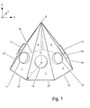
- defined directions for the housing of a measuring device of the type presented here are defined, for example by a pyramid, with respect to a fixed xyz coordinate system predetermined by the apparatus.
- Their side surfaces 1, 2, 3, 4, 5, 6 and 7 have a common corner S and bottom edges 21, 22, 23, 24, 25, 26 and 27, which define the base of the pyramid.
- the individual side surfaces thus differ clearly in their directional cosine values.
- a single side surface reference numerals 1 to 7
- a single, eg micromechanical or thermodynamically functioning inclinometer is attached (reference numerals 11, 12, 13, 14, 17; the remaining four single inclinometers are not shown for reasons of clarity).
- a single inclinometer can then be identified with respect to its own coordinate system by at least one vector, each defining a systemic direction of action. This may be, for example or preferably, a normal vector which is then perpendicular to, or optionally parallel, to the relevant side surface of the pyramid.
- the directional cosine values or other useful directional characteristics for specifying a significant reference direction of the individual inclinometers relative to the xyz coordinate system shown may be specified.
- a rotational or tilting movement of the device-fixed coordinate system can thus be measured according to two axes of the space.
- the measurement result can be displayed after conversion in the form of pitch and roll values.
- the ratio of the height h to the radius r of an underlying pyramidal body should have a value of approximately 0.2 to 1.2 in the arrangement shown.
- a preferred value is 0.55.
- gauges of the generic type as they are used for measuring roles in paper and rolling mills, anyway of rather elongated shape and therefore room for a relatively large number of individual Inclinometersysteme, with different orientation relative to Housing of such a meter, offer.
- a regular octahedron in general: k single inclinometers parallel or normal to the faces, sides, bisectors, and / or corners of a regular polyhedron.
- the differences in direction between the individual inclinometers are on average greater than in the case of in Fig. 1 arrangement shown.
- the calculation of the different inclinometer combinations is simplified because of symmetry properties, so that such an arrangement works even more efficiently, i. provides a further improved measurement result with little increase in material costs; etc.
- FIG 2 shows how an overall system according to the invention is composed of a housing 100, inclinometers 11 to incl. 17 arranged individually in this housing, a computer 50 for interrogating the signals emitted by the inclinometers and for determining a result in FIG Shape of an orientation value. This result can be displayed on a viewing screen 70.
- the Operation of the overall system is preferably by means of a keyboard 60, although other input means (mouse, trackball, stylus, speech, etc.) may be provided.
- the entire system is preferably powered by a battery or accumulator 80, if necessary, a network connection can be provided.
- the proposed Anor Aunt can be operated as described on its own. However, it is used with particular advantage in interaction with a similarly working combination of gyroscopes, especially MEMS gyroscopes incl.
- Thermodynamically operating gyroscopes which is arranged within a common housing. With such a gyroscope combination, it is known to be possible to measure not only the pitch and roll inclination values, but also to detect the yaw azimuth value.
- the mentioned inclusions and azimuth values are subject to disturbing drift errors.
- the inclinometer device presented according to the present invention operates statically, its drift over time is much smaller than with a gyroscope.
- a combination of inclinometers and gyroscopes can be temporarily fixed again and again for a while (and then accurately register the magnitude and direction of gravitational acceleration), the two components can The roll and pitch of the gyroscope values are corrected by the respective components of the inclinometer values, ie they are "supported". In this way, an additional estimate can be made to what extent the yaw value provided by the gyroscopes can be reduced to a presumed best value.
- the measuring device is to compare a current gyroscope-based directional measurement with respect to its azimuthal (yaw) rotational movement to a presumed best value in the fastest possible sequence using current inclinometer-based roll and pitch direction measurement results, the presumed best value being based on a predefined or adaptable Algorithm is calculated.
- Said adaption may, for example, be carried out using temperature measurements on the individual sensors or within the device, or on the basis of a quality estimate for a measurement carried out.
- a significant improvement of said gyroscope-based directional measurement is achieved, typically by at least an order of magnitude.
- the invention is preferably used in the surveying of buildings, of machine tools, or on machines which serve for the production or processing of metal, paper or plastic films. Furthermore, the invention is used with very particular advantage in equipment that serve petroleum prospecting or promotion.
Abstract
Description
Die Erfindung betrifft ein Meßgerät zur präzisen Bestimmung der räumlichen Orientierung eines Körpers relativ zu zwei horizontalen Bezugsrichtungen, so daß die Bestimmung sowohl eines Nickwinkels (englisch: pitch) als auch eines Rollwinkels (englisch: roll) in verbesserter und sehr genauer Weise durchgeführt werden kann. Dabei sollte der Körper zur Ausführung der Messung raumfest gelagert und unbewegt sein, zumindest darf (und muß) während der Ausführung der Messung auf den Körper lediglich die Erdbeschleunigung auf diesen wirken. Insofern ist die Erfindung nicht für Anwendungen bei Schwerelosigkeit im Weltraum geeignet. Weiterhin betrifft die Erfindung zumindest ein Verfahren zur Bereitstellung eines Gesamt-Meßergebnisses aus Einzel-Meßergebnissen, welche von Inclinometer-Subsystemen bereitgestellt werden. Außerdem betrifft die Erfindung die Verwendung des Meßgerätes zum Bestimmen zweier Komponenten der räumlichen Orientierung von Maschinen oder Maschinenelementen wie z.B. Rollen oder Walzen, sowie zur Bereitstellung von Korrektur-Informationen, um dejustierte Maschinen oder Maschinenelemente in eine ausgerichtete Lage zu bringen, weiterhin auch die Verwendung des Meßgerätes zur Richtungsermittlung an anderen Objekten.The invention relates to a measuring device for the precise determination of the spatial orientation of a body relative to two horizontal reference directions, so that the determination of both a pitch and a roll angle can be performed in an improved and very accurate manner. In this case, the body should be stored fixed space and immobile to perform the measurement, at least may (and must) during the execution of the measurement on the body only the gravitational act on this. In this respect, the invention is not suitable for applications in weightlessness in space. Furthermore, the invention relates to at least one method for providing an overall measurement result from individual measurement results provided by inclinometer subsystems. Moreover, the invention relates to the use of the measuring device for determining two components of the spatial orientation of machines or machine elements such as e.g. Rolling or rolling, as well as providing correction information to bring misaligned machines or machine elements into an aligned position, further including the use of the measuring device for directional determination on other objects.
Zum Zwecke der Bestimmung der räumlichen Orientierung eines Körpers relativ zu einer Bezugsrichtung, und absolut innerhalb eines Inertialsystems, ist es seit einiger Zeit bekannt, genaue Kreiselsysteme zu verwenden. Neben mechanischen Kreiseln, deren Präzision durch mechanische Randbedingungen limitiert wird, sind seit einiger Zeit Kreisel auf optischer Basis, insbesondere in der Ausführungsform mit einem sog. Ringlaser, als hochgenaue Richtungsund Orientierungs-Meßgeräte auf dem Markt. Eine solche Einrichtung ist aus der Patentschrift US 6195615 bekannt. Leider sind die Kosten für besonders genaue Instrumente dieser Art von erheblichem Umfang, so daß es von signifikantem Interesse ist, die Kosten/Nutzen-Relation solcher Meßgeräte deutlich zu verbessern.For the purpose of determining the spatial orientation of a body relative to a reference direction, and absolutely within an inertial system, it has been known for some time to use accurate gyro systems. In addition to mechanical gyroscopes, the precision of which is limited by mechanical boundary conditions, gyros on the optical basis, in particular in the embodiment with a so-called ring laser, have been on the market for some time now as highly accurate directional and orientation gauges. Such a device is known from the patent US 6195615. Unfortunately, the cost of particularly accurate instruments of this type is considerable, so that it is of significant interest to significantly improve the cost / benefit ratio of such instruments.
Auch in der DE 195 46 405 wird ein hochgenaues Kreiselsystem auf optischer Basis beschrieben, welches zum gegenseitigen Ausrichten von Körpern, insbesondere für Wellen, Walzen u. dgl. vorgesehen ist.Also in DE 195 46 405 a highly accurate gyro system is described on an optical basis, which u for mutual alignment of bodies, in particular for shafts, rollers and. Like. Is provided.
Ein in der DE 42 05 869 angegebenenes Verfahren ist noch erheblich aufwendiger, da ein doppelter Satz an Kreiselsystemen für die Messung vorgesehen ist.A specified in DE 42 05 869 method is still considerably more expensive, since a double set of gyro systems is provided for the measurement.
Äußerst aufwendig ist die in der US 5,719,764 vorgestellte Lösung. Zum einen sind redundante Kontrollkreisel und -Akzelerometer vorgesehen, welche eine Kurzfrist- und eine Langfrist-Fehlerabschätzung durchführen. Zum anderen ist vorgesehen, je zwei solcher Systeme zu einem im Tandem-Verbund arbeitenden doppelt abgesicherten Gerät zusammenzuschalten.Extremely expensive is the solution presented in US Pat. No. 5,719,764. On the one hand redundant control gyros and accelerometers are provided, which perform a short-term and a long-term error estimation. On the other hand, it is envisaged to interconnect two such systems into one tandem composite double-fused device.
Eine relativ preiswerte, aber weniger genau funktionierende Lösung ist aus der DE 198 00 901 bekannt, welche anstelle optischer Kreisel solche auf Basis mechanischer Oszillatoren vorsieht.A relatively inexpensive, but less accurate solution is known from DE 198 00 901, which provides instead of optical gyroscope on the basis of mechanical oscillators.
Aus der DE 198 30 359 ist eine Vorrichtung und ein Verfahren bekannt, die räumliche Lage und Bewegungen eines (humanen) Körpers oder von Körperteilen zu bestimmen, wobei an die Genauigkeit der Meßergebnisse weniger hohe Anforderungen gestellt werden, als an die zeitliche Verfügbarkeit, d.h. zeitliche Auflösung, solcher Daten.From DE 198 30 359 an apparatus and a method is known to determine the spatial position and movements of a (human) body or parts of the body, wherein the accuracy of the measurement results less stringent requirements, as to the temporal availability, i. temporal resolution, such data.
Aus der DE 199 49 834 vom 19.4.2001 ist ein Verfahren bekannt, welches es gestattet, die Genauigkeit der Lösung gemäß DE 195 46 405 noch einmal erheblich zu steigern, wobei nur der Software-Aufwand zusätzlich ins Gewicht fällt, der apparative Aufwand jedoch der gleiche bleiben kann.From DE 199 49 834 of 19.4.2001 a method is known which makes it possible to increase the accuracy of the solution according to DE 195 46 405 again considerably, with only the software overhead is of additional importance, the apparatus required but the can stay the same.
Eine weitere Verwendung von kreiselbasierten Richtungsmeßgeräten wird in der DE 100 60 974 vom 30. 8. 2001 vorgestellt. Das Gerät ist dafür vorgesehen, mittels eines Adapters auf die stirnseitigen Enden von Walzen positioniert werden zu können; es ist zusätzlich mit einer Positionsmeßvorrichtung auf Laserbasis ausgestattet.Another use of gyro-based Richtungsmeßgeräten is presented in DE 100 60 974 from 30. 8. 2001. The device is intended to be positioned by means of an adapter on the front ends of rollers can; It is additionally equipped with a laser-based position measuring device.
Aus der DE 10115548 ist es bekannt, kreiselbasierte Richtungsmeßgeräte mit mehr als drei Einzelkreiseln zu verwenden, welche z.B. parallel zu den Normalen oder sonstigen Symmetrielinien eines regulären Oktaeders oder Ikosaeders usw. montiert sind. Hierdurch wird es möglich, ein Gerät mit verbesserter Meßgenauigkeit bereitzustellen, da einerseits mit statistischen Methoden gearbeitet werden kann (was bei nur drei Einzelkreiseln praktisch nicht möglich ist) und darüberhinaus auch eine gegenseitige Überprüfung der Einzelkreisel durchgeführt werden kann.From DE 10115548 it is known to use gyro-based directional gauges with more than three individual gyros, which are mounted, for example, parallel to the normal or other symmetry lines of a regular octahedron or icosahedron, etc. This makes it possible to provide a device with improved accuracy, since on the one hand with statistical methods can be worked (which is practically impossible with only three individual gyros) and also a mutual review of the individual gyros can be performed.
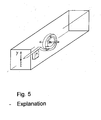
Die genannte Aufgabenstellung liegt der in der vorliegenden Anmeldeschrift dargestellten Erfindung zugrunde. Die Erfindung löst das anstehende Problem dadurch, daß eine redundante Auslegung eines mit Inklinometern ausgestatteten zweidimensional sensierenden Richtungsmeßsystems vorgenommen wird, so daß dessen funktionale Eigenschaften sowohl hinsichtlich Betriebssicherheit, als auch insbesondere auch hinsichtlich Genauigkeit verbessert werden. Gleichzeitig reduzieren sich, sofern weniger genaue und damit kostengünstigere einzelne Systeme verwendet werden, die Gestehungskosten des Gesamtsystems. Mit anderen Worten: Die Erfindung sieht vor, anstelle eines Inclinometersystems bestehend aus zwei orthogonal zueinander ausgerichteten Einzel-Inclinometern nunmehr ein solches System vorzusehen, welches aus mindestens drei, bevorzugt vier oder aber weiteren Einzel-Inclinometern besteht. Dies sind bevorzugt MEMS-Inclinometer, die einzeln zwar nicht die Richtung einer Beschleunigung angeben können (im Gegensatz zu einfachen Flüssigkeits-Inclinometern gemäß Fig. 3 und 4), dafür aber geeignet sind, die Größe einer zugehörigen Beschleunigungskomponente zu ermitteln, wie dies in Fig. 5 anhand der gezeigten einfachen Feder-Masse-Kombination angedeutet ist. -
Gemäß dem unabhängigen Anspruch 1 kann die Lösung des zugrundeliegenden Problems durch Implementation der folgend genannten Prinzip-Anordnung bereitgestellt werden:
Meßgerät zur Bestimmung der räumlichen Orientierung eines Körpers relativ zu zwei in einer insbesondere horizontalen Ebene liegenden Bezugsrichtungen, mit einem Gehäuse zum Anlegen an eine Oberfläche oder an eine Kante eines zu vermessenden Körpers, mit einer Mehrzahl von Inclinometersystemen zur Ermittlung von stabilen Raumlagen oder von Kipp- oder Drehbewegungen relativ zu vordefinierten Inertialrichtungen, wobei zumindest drei und bevorzugt vier oder mehr Einzelinclinometer innerhalb des Gehäuses vorhanden sind, deren jeweilige Referenz- oder Wirkrichtung zur Erfassung eines Anteils der Erdbeschleunigung nach unterschiedlichen Richtungen des Raumes orientiert sind, und wobei eine jede der Kombinationen aus jeweils drei zu einer Inclinometertriade zusammengefaßten, ein Inclinometersystem bildenden Einzelinclinometern ein jeweils erstes Meßergebnis liefern, welches die räumliche winkelmäßige Orientierung des Meßgerätes oder eines mit diesem kontaktierten Körpers nach den (raumfesten) Richtungskordinaten Roll und Pitch ausweist, so daß mehrere Meßergebnisse erster Art ermittelbar sind; und daß weiterhin aus den Meßergebnissen erster Art durch Mittelwertbildung oder andere Rechenverfahren wie z.B. digitale Filterung ein Meßergebnis zweiter Art als Gesamt-Meßergebnis bereitstellbar ist, welches eine genauere winkelmäßige Orientierung des Meßgerätes oder eines mit diesem kontaktierten Körpers hinsichtlich der genannten Richtungskoordinaten Roll und Pitch ausweist, im Vergleich zu einzelnen Meßergebnissen der ersten Art.The stated task is based on the invention described in the present application. The invention solves the problem at hand by providing a redundant design of a two-dimensional sensing direction measuring system equipped with inclinometers so that its functional properties are improved both in terms of operational reliability and, in particular, accuracy. At the same time, if less accurate and thus less expensive individual systems are used, the production costs of the entire system are reduced. In other words, instead of an inclinometer system comprising two orthogonally oriented single inclinometers, the invention provides for such a system which consists of at least three, preferably four or further individual inclinometers. These are preferably MEMS inclinometers which individually can not indicate the direction of an acceleration (in contrast to simple liquid inclinometers according to FIGS. 3 and 4), but are suitable for determining the size of an associated acceleration component, as shown in FIG 5 is indicated on the basis of the simple spring-mass combination shown. -
According to
Measuring device for determining the spatial orientation of a body relative to two reference directions lying in a horizontal plane in particular, with a housing for application to a surface or edge of a body to be measured, with a plurality of inclinometer systems for determining stable space positions or tilting systems. or rotational movements relative to predefined inertial directions, wherein at least three and preferably four or more single inclinometers are present within the housing, whose respective reference or effective direction for detecting a proportion of gravitational acceleration are oriented in different directions of the space, and wherein each of the combinations of three individual inclinometers, which are combined to form an inclinometer triad and form an inclinometer system, respectively provide a first measurement result which determines the spatial angular orientation of the measuring instrument or one with the latter contacted body after the (fixed space) direction coordinates roll and pitch identifies, so that a plurality of measurement results of the first kind can be determined; and that further from the measurement results of the first kind by averaging or other computational methods such as digital filtering a measurement result of the second kind as a total measurement result can be provided, which identifies a more accurate angular orientation of the measuring device or a body contacted with this body with respect to the directional coordinates Roll and Pitch, in comparison to individual measurement results of the first kind.
Eine rechentechnisch interessante Ausführungsform der Erfindung besteht z.B. aus acht symmetrisch um eine Achse oder um ein Zentrum angeordneten Einzelinclinometern. Unabhängig davon, ob es sich um preiswerte oder qualitativ hochwertige Einzel-Inclinometer handelt, kann in jedem Fall durch Kombination einer Vielzahl von gleichartigen, oder aber auch unterschiedlich konstruierten, Einzel-Inclinometern eine überproportional verbesserte Genauigkeite bereitgestellt werden, da es teilweise möglich ist, Temperatur- und Schwerkrafteffekte durch Differenzbildung, Mittelwertbildung oder andere statistische Betrachtungen zu kompensieren. Außerdem werden durch die gemäß der Erfindung vorgesehene innovative, d.h. nunmehr dreidimensionale, also insbesondere nicht koplanare Anordnung der Einzelsensoren, im Gegensatz zu den vorher bekannten zweidimensionalen Anordnungen, bessere Berechnungsgrundlagen zur Bereitstellung eines Meßergebnisses geschaffen, so daß auch aus diesem Grunde ein besser funktionierendes Inclinometer-Gesamtsystem bereitgestellt werden kann. Dies ist ein besonders wichtiger Aspekt der vorliegenden Erfindung. Beispielsweise werden gemäß der Erfindung typischerweise alle verwendbaren, d.h. nicht koplanaren Kombinationen von 3 aus insgesamt "k" Stück einzelner Inclinometer-Meßwerte zur Bildung einzelner individueller Inclinometer-Meßwert-Triaden herangezogen, um eine Mehrzahl von unabhängigen Richtungsmessungen mit derartig gebildeten Inclinometer-Triaden ausführen zu können. Da bei dem genannten Beispiel von 3 aus 8 Inclinometern also maximal (n über k = ) 56 einzeln auswertbare Meß-Systeme zur Erkennung einer winkelmässigen Orientierung des Meßgerätes nach zwei Koordinaten im Raum darstellbar sind, kann die Genauigkeit eines insgesamt bereitzustellenden Meßergebnisses hinsichtlich Drift und weiterer Fehler durch Mittelwertbildung oder weitere statistische Betrachtungen, oder durch andere Rechenverfahren wie z.B. digitale Filterung, signifikant verbesssert werden. Gleichzeitig können sich die vielen genannten Meßsysteme, bestehend aus nunmehr je drei einzelnen Inclinometern, gegenseitig überprüfen, so daß Einzel-Inclinometer mit verschlechterten Meß-Eigenschaften gemäß der Erfindung bereits während des regulären Betriebes identifiziert und gegebenenfalls stillgelegt werden können. Wie erwähnt, liegt erfindungsgemäß eine zusätzlich erwünschte Redundanz vor, so daß ein Meßsystem der vorgeschlagenen Art, mit beispielweise mindestens 4 Einzelinclinometern, bei Ausfall eines einzelnen Inclinometers trotzdem weiterhin benutzbar ist, wenn auch bei reduzierter Genauigkeit. Gemäß der Erfindung wird also ein Meßgerät zur Bestimmung der räumlichen Orientierung eines Körpers relativ zu zwei in einer Horizontalebene liegenden Bezugsrichtungen geschaffen, welches ein Gehäuse zum Anlegen an eine Oberfläche eines zu vermessenden Körpers aufweist, innerhalb dessen eine Mehrzahl von einzelnen Inclinometern zur Ermittlung eines anteiligen Wertes der Erdbeschleunigung bezüglich jeweiliger, den einzelnen Inclinometern zugeordneten Symmetrieachsen versehen ist, und wobei sich das Meßgerät dadurch auszeichnet, daß mindestens drei, bevorzugt jedoch vier oder viele weitere, Einzelinclinometer innerhalb des Gehäuses vorhanden sind, die möglichst nicht-koplanar in jeweils unterschiedliche Raumrichtungen orientiert oder ausgerichtet sind, und wobei alle Kombinationen aus jeweils drei nicht-koplanar orientierten, zu einer sog. Inclinometertriade zusammenfaßbarer, Einzelinclinometer ein jeweils erstes Meßergebnis liefern, welches die räumliche winkelmäßige Orientierung des Meßgerätes oder eines mit diesem kontaktierten Körpers nach den beiden räumlichen Koordinaten "Roll" und ""Pitch" ausweist. Diese erfindungsgemäße Anordnung wird so benutzt, daß zunächst eine Vielzahl an Meßergebnissen erster Art bereitgestellt wird, und sodann aus der Vielzahl der Meßergebnisse erster Art zusätzlich ein Gesamt-Meßergebnis (d.h. Meßergebnis zweiter Art) ermittelt wird, welches im Vergleich zu den einzelnen Meßergebnissen erster Art eine signifikant genauere winkelmäßige Orientierung des Meßgerätes oder eines mit diesem kontaktierten Körpers anzeigt. Gemäß einem anderen Aspekt der Erfindung kann aus der Vielzahl der Meßergebnisse erster Art unter Verwendung eines geeigneten mathematischen Algorithmus wie z.B. SVD (Singulärmatrixzerlegung) auch sofort ein signifikant genaueres Meßergebnis bereitgestellt werden.A computationally interesting embodiment of the invention consists, for example, of eight single linear meters arranged symmetrically about an axis or about a center. Regardless of whether they are low-cost or high-quality single inclinometers, disproportionately improved accuracies can be provided in any case by combining a large number of identical or differently constructed individual inclinometers, since it is sometimes possible to determine temperature and compensate for gravity effects by subtraction, averaging or other statistical considerations. In addition, provided by the invention provided in accordance with the invention innovative, ie now three-dimensional, ie in particular non-coplanar arrangement of the individual sensors, in contrast to the previously known two-dimensional arrangements, better calculation bases to provide a measurement result, so that for this reason a better functioning Inclinometer- Entire system can be provided. This is a particularly important aspect of the present invention. For example, according to the invention, typically all usable, ie non-coplanar, combinations of 3 out of a total of "k" pieces of individual inclinometer measurements are used to form individual individual inclinometer sample triads to perform a plurality of independent direction measurements with thus formed inclinometer triads can. Since in the mentioned example of 3 out of 8 inclinometers a maximum of (n over k =) 56 individually evaluable measuring systems for detecting a angular orientation of the measuring device according to two coordinates in space can be represented, the accuracy of a total to be provided measurement result in terms of drift and more Error by averaging or other statistical considerations, or by others Calculation methods such as digital filtering, be significantly improved. At the same time, the many measurement systems mentioned, consisting of now three individual inclinometers, can mutually check each other, so that individual inclinometers with deteriorated measuring characteristics according to the invention can already be identified during normal operation and possibly shut down. As mentioned, according to the invention an additionally desired redundancy is present, so that a measuring system of the type proposed, with, for example, at least 4 Einzelinclinometern, in case of failure of a single Inclinometer still still usable, albeit with reduced accuracy. According to the invention, therefore, there is provided a measuring device for determining the spatial orientation of a body relative to two reference directions lying in a horizontal plane, comprising a housing for application to a surface of a body to be measured, within which a plurality of individual inclinometers for determining a proportional value the gravitational acceleration is provided with respect to respective axes of symmetry associated with the individual inclinometers, and wherein the measuring device is characterized in that at least three, but preferably four or many further, single inclinometers are provided within the housing, which are oriented as non-coplanar as possible in different spatial directions are aligned, and wherein all combinations of three non-coplanar oriented, to a so-called. Inclinometertriade summarized, Einzelinclinometer provide a first measurement result, which is the spatial angular Orientation of the measuring device or a body contacted with this according to the two spatial coordinates "roll" and "" Pitch identifies. This arrangement according to the invention is used so that initially a plurality of measurement results of the first kind is provided, and then from the plurality of measurement results of the first kind in addition a total measurement result (ie measurement result of the second kind) is determined, which in comparison to the individual measurement results of the first kind indicates a significantly more accurate angular orientation of the meter or a contacted with this body. According to another aspect of the invention, a significantly more accurate measurement result can be immediately provided from the plurality of measurement results of the first type using a suitable mathematical algorithm such as SVD (singular matrix decomposition).
Die Anzahl von acht Inclinometer-Einzelsystemen innerhalb eines Gesamtsystems gemäß der Erfindung ist nur als Beispiel zu verstehen. Es können z.B. auch vier, fünf, sechs usw.The number of eight individual inclinometer systems within an overall system according to the invention is to be understood as an example only. It can also be four, five, six, etc.
Inclinometer oder eine wesentlich größere Anzahl verwendet werden, zum Beispiel 150 bis 400 miniaturisierte Elemente dieser Art, insbesondere solche, deren Ausgangssignal im wesentlichen sinusoidförmig über den Pitch- und Rollwinkel variiert, oder die anhand einer Korrekturwert-Tabelle entsprechend kompensiert werden können. - Die gewählte Zahl der Einzel-Inclinometer sollte jedoch zu einem Kompromiß hinsichtlich apparativem Aufwand und erzielbarer Genauigkeitssteigerung führen. Ein solcher Kompromiß hängt ersichtlich auch davon ab, welcher Kostenanteil für eine erforderliche zusätzliche Recheneinheit zum Errechnen des gewünschten Gesamt-Resultates zu veranschlagen ist. Für die sehr klein konstruierten, äußerst stromsparenden und sehr preiswerten MEMS-Inclinometer (im Kostenbereich von derzeit ca. EUR 5.-- pro Exemplar) erscheint es gemäß der Erfindung vorteilhaft, ca. 150 einzelne Inclinometer zu einem Gesamtsystem zusammenzufassen. Aus Gründen einer erleichterten Datenverarbeitung sollen die einzelnen Inclinometer vorzugsweise ein pulscodemoduliertes Ausgangssignal bereitstellen. Auf diese Weise kann das sogenannte Multiplexen oder die Verwendung einer Vielzahl von herkömmlichen Analog-Digital-Wandlern vermieden werden. Am besten geschieht dies in an sich bekannter Weise unter Verwendung digitaler sogenannter Timer/Counter-Bauelemente, speziell unter Verwendung handelsüblicher miniaturisierter Präzisions-Zeitgeber mit Genauigkeiten von im Bereich von mindestens 10 (E-6) oder besser.Inclinometer or a significantly larger number are used, for example, 150 to 400 miniaturized elements of this type, in particular those whose output varies substantially sinusoidally over the pitch and roll angle, or which can be compensated according to a correction value table accordingly. - The selected number of single Inclinometer should lead to a compromise in terms of equipment complexity and achievable accuracy increase. Such a compromise obviously also depends on what proportion of costs is to be estimated for a required additional arithmetic unit for calculating the desired overall result. For the very small constructed, extremely low-power and very inexpensive MEMS inclinometer (in the cost range of currently about EUR 5 .-- per copy) it seems advantageous according to the invention to summarize about 150 individual inclinometers to form an overall system. For reasons of facilitating data processing, the individual inclinometers should preferably provide a pulse code modulated output signal. In this way, the so-called multiplexing or the use of a variety of conventional analog-to-digital converters can be avoided. This is best done in a conventional manner using digital so-called timer / counter components, especially using commercially available miniaturized precision timer with accuracies of in the range of at least 10 (E-6) or better.
Gemäß der Erfindung ist es wie erwähnt möglich, die vorgesehenen Einzelsysteme symmetrisch um eine einzelne Vorzugsachse zu gruppieren. Es ist ebenfalls möglich, die Orientierung der Einzelsysteme nach Symmetrierichtungen eines regulären Polyeders, oder aber annähernd statistisch über den Raumwinkel (4 * Pi) zu verteilen. Es sollte aber gewährleistet sein, daß die einzelnen Orientierungen der Einzelsysteme hinsichtlich eines gerätefesten Koordinatensystemes genügend fest montiert sind und auch nur geringe thermisch bedingte Richtungsänderungen innerhalb des Gehäuses erfahren. Es versteht sich von selbst, daß auch die Konstruktion des Gehäuses genügend formstabil sein muß. Weiterhin ist es wie bereits erwähnt wichtig, daß die jeweils drei Einzelinclinometern zugeordneten Richtungs-Vektoren nicht räumlich koplanar liegen. Gemäß der Erfindung werden die Meßwerte, die von den Einzelinclinometern typischerweise in einem schiefwinkligen dreidimensionalen Koordinatensystem ermittelt werden, auf ein rechtwinkliges kartesisches Koordinatensystem umgerechnet. Die Rechenverfahren für eine solche Umrechnung sind an sich bekannt. Auf diese Weise können ausgegebene Meßwerte z.B. in zwei der drei Eulerschen Winkel (nämlich Stampf- und Rollwinkel bzw. Pitch und Roll) bezüglich eines solchen rechtwinkligen Koordinatensystems ausgedrückt werden. Eine Bereitstellung eines Meßwertes für den Gierwinkel (Yaw) mittels Inclinometer allein ist ersichtlich nicht möglich. - Die genannte Umrechnung wird, genauso wie die statistischen Berechnungen, durch einen in einem umschließenden Gehäuse des Meßgerätes vorgesehenen Computer vorgenommen. Zur Einsparung von Versorgungsleistung kann dessen Taktfrequenz reduziert werden, sobald ersichtlich ist, daß keine aktuelle Messung auszuführen ist. Dies kann z.B. dadurch begründet sein, daß eine sensierte räumliche Lage des erfindungsgemäßen Gerätes sich nicht verändert und als stabil angenommen werden kann.According to the invention, it is possible, as mentioned, to group the individual systems provided symmetrically about a single preferred axis. It is also possible to distribute the orientation of the individual systems according to symmetry directions of a regular polyhedron, or approximately statistically over the solid angle (4 * Pi). However, it should be ensured that the individual orientations of the individual systems with respect to a device-fixed coordinate system are sufficiently fixed and experienced even small thermally induced changes in direction within the housing. It goes without saying that the construction of the housing must be sufficiently dimensionally stable. Furthermore, as already mentioned, it is important that the direction vectors associated with each three individual inclinometers are not spatially coplanar. According to the invention, the measured values, which are determined by the Einzelinclinometern typically in a skewed three-dimensional coordinate system, converted to a rectangular Cartesian coordinate system. The calculation methods for such a conversion are on known. In this way, output measured values can be expressed, for example, in two of the three Euler angles (namely, pitch and roll pitch) with respect to such a rectangular coordinate system. A provision of a measured value for the yaw angle (yaw) by means of inclinometer alone is obviously not possible. - The said conversion is made, as well as the statistical calculations, by a computer provided in an enclosing housing of the measuring device. To save supply power whose clock frequency can be reduced as soon as it is clear that no current measurement is to be performed. This may be due, for example, to the fact that a sensed spatial position of the device according to the invention does not change and can be assumed to be stable.
Diese und weitere Einzelheiten der Erfindung werden anhand der Zeichnung erläutert. Es zeigt:
- Fig. 1
- eine axial-
symmetrische Anordnung von 7 Einzelinclinometern relativ zu einem x-y-z - Koordinatensystem - Fig. 2
- eine schematische Darstellung einer
Systemkonfiguration mit 7 Einzelinclinometern - Fig. 3
- ein herkömmliches Flüssigkeits-Inclinometer (Wasserwaage) nach dem Stand der Technik
- Fig. 4
- eine andere herkömmliche Wasserwaage nach dem Stand der Technik
- Fig. 5
- ein modellhaft gezeigtes mechanisches Inclinometer zur Erfassung einer vertikal gerichteten Schwerkraftkomponente
- Fig. 1
- an axially symmetric arrangement of 7 Einzelinclinometern relative to an xyz - coordinate system
- Fig. 2
- a schematic representation of a system configuration with 7 Einzelinclinometern
- Fig. 3
- a conventional liquid Inclinometer (spirit level) according to the prior art
- Fig. 4
- another conventional spirit level according to the prior art
- Fig. 5
- a model shown mechanical Inclinometer for detecting a vertically directed gravity component
Wie aus Fig. 1 ersichtlich, werden definierte Richtungen für das Gehäuse eines Meßgerätes der hier vorgestellten Art bezüglich eines gerätefest vorgegebenen x-y-z- Koordinatensystems z.B. durch eine Pyramide definiert. Deren Seitenflächen 1, 2, 3, 4, 5, 6 und 7 besitzen eine gemeinsame Ecke S sowie Grundkanten 21, 22, 23, 24, 25, 26 und 27, welche die Grundfläche der Pyramide begrenzen. Die einzelnen Seitenflächen unterscheiden sich also eindeutig in ihren Richtungs-Cosinus-Werten. Auf eine einzelne Seitenfläche (Bezugsziffer 1 bis 7) werde jeweils ein einzelnes, z.B. mikromechanisches oder thermodynamisch funktionierendes Inclinometer angebracht (Bezugsziffern 11, 12, 13, 14, 17; die restlichen vier Einzelinclinometer sind aus Gründen der Übersichtlichkeit nicht gezeigt). Ein einzelnes Inclinometer kann dann bezüglich seines eigenen Koordinatensystems durch mindestens einen Vektor gekennzeichnet werden, der jeweils eine systembedingte Wirkungsrichtung definiert. Dies kann beispielsweise bzw. bevorzugt ein Normalen-Vektor sein, der dann senkrecht auf, oder gegebenenfalls parallel, zur betreffenden Seitenfläche der Pyramide liegt. Somit können die Richtungs-Cosinus-Werte oder andere verwendbare Richtungs-Kennwerte zur Spezifikation einer maßgeblichen Referenz-Richtung der einzelnen Inclinometer relativ zum gezeigten x-y-z-Koordinatensystem genau angegeben werden. Durch eine Kombination von je drei beliebig gewählten Inclinometern (Triaden) kann somit auch eine Dreh- oder Kipp-Bewegung des gerätefesten Koordinatensystems nach zwei Achsen des Raumes ausgemessen werden. Das Meßergebnis kann nach Umrechnung in Form von Pitch- und Rollwerte dargestellt werden. Voraussetzung ist, daß die genannten Referenz-Richtungen der einzelnen Inclinometer nicht paarweise koplanar sind. Insofern ist die zu erwartende Genauigkeit der einzeln darstellbaren Triaden aus Fig. 1 nicht gleichwertig, vielmehr sind gewisse Kombinationen durch höhere Genauigkeit ausgezeichnet als z.B. eine Triade von direkt benachbarten Inclinometern 11, 12, 13.As can be seen from FIG. 1, defined directions for the housing of a measuring device of the type presented here are defined, for example by a pyramid, with respect to a fixed xyz coordinate system predetermined by the apparatus. Their side surfaces 1, 2, 3, 4, 5, 6 and 7 have a common corner S and
Da in der abgebildeten Konfiguration insgesamt 35 voneinander unabhängige Inclinometer-Triaden angegeben werden können, kann die Beobachtung der genannten Dreh- oder Kipp-Bewegung, mithin auch die Vermessung der Relativlage eines Körpers bezüglich zweier horizontal liegender Referenzrichtungen, sich auf 35 Einzelmessungen beziehen. Im Idealfalle würden alle Einzelmessungen ein gleiches Ergebnis liefern. Die einzelnen Konfigurationen arbeiten jedoch, wie bereits dargestellt, mit unterschiedlicher Genauigkeit. Die Einzelmessungen werden daher bevorzugt so zu einem Gesamtwert zusammengefaßt, daß die genauer arbeitenden Inclinometertriaden mit einem höheren Gewicht bei einer durchzuführenden Mittelwertbildung versehen werden. Solche genauer funktionierende Inclinometertriaden sind also z.B. solche, deren Abstände nicht kleiner als 2 Positionen sind.Since in the illustrated configuration, a total of 35 independent inclinometer triads can be specified, the observation of said tilt or tilt movement, and thus the measurement of the relative position of a body with respect to two horizontal reference directions, refer to 35 individual measurements. Ideally all single measurements would give the same result. However, the individual configurations work with different accuracy, as already explained. The individual measurements are therefore preferably combined to a total value so that the more accurate Inclinometertriaden be provided with a higher weight at averaging to be performed. Such more precisely functioning Inclinometertriaden are eg such, whose distances are not smaller than 2 positions.
Am wenigsten genau messen typischerweise diejenigen Inclinometertriaden, deren Inclinometer direkt beabstandet sind d.h. keine Zwischenräume aufweisen und deren Referenzrichtungen somit nur ein kleinvolumiges Epiped aufspannen.Least precisely, typically, those inclinometer triads whose inclinometers are directly spaced, i. have no gaps and their reference directions thus span only a small-volume epiped.
Zur Erzielung eines guten Meßergebnisses sollte in der gezeigten Anordnung das Verhältnis der Höhe h zum Radius r eines zugrundegelegten Pyramidenkörpers etwa einen Wert von 0,2 bis 1,2 aufweisen. Ein bevorzugter Wert liegt bei 0,55. - Bei einem ca. zweifachen Materialeinsatz im Vergleich zu einer herkömmlichen zweidimensionalen Inclinometeranordnung kann also gemäß der Erfindung ein mehrfaches, z.B. ca. 3-4 fach genaueres Ergebnis erhalten werden usw. Der Sinn und der wesentliche Vorteil der Erfindung besteht also darin, ein bevorzugt mehrfach redundantes Inclinometersystem bereitzustellen, dessen Genauigkeit überproportional zum Materialeinsatz steigt. Ein zusätzlicher Vorteil der Erfindung kann darin erkannt werden, daß Meßgeräte der gattungsgemäßen Art, wie sie zum Vermessen von Rollen in Papier- und Walzwerken verwendet werden, ohnehin von eher langgestreckter Gestalt sind und daher Platz für relativ viele einzelne Inclinometersysteme, mit unterschiedlichster Ausrichtung relativ zum Gehäuse eines solchen Meßgerätes, bieten.To achieve a good measurement result, the ratio of the height h to the radius r of an underlying pyramidal body should have a value of approximately 0.2 to 1.2 in the arrangement shown. A preferred value is 0.55. When using about twice the material compared to a conventional two-dimensional Inclinometeranordnung so according to the invention, a multiple, e.g. The meaning and the essential advantage of the invention is therefore to provide a preferably multi-redundant Inclinometersystem whose accuracy increases disproportionately to the use of materials. An additional advantage of the invention can be seen in the fact that gauges of the generic type, as they are used for measuring roles in paper and rolling mills, anyway of rather elongated shape and therefore room for a relatively large number of individual Inclinometersysteme, with different orientation relative to Housing of such a meter, offer.
In einer bevorzugten, nicht gezeigten Ausgestaltung der Erfindung liegen z.B. acht Einzelinclinometer auf den Flächen eines regelmäßigen Oktaeders (allgemein: k Einzelinclinometer parallel oder normal zu den Flächen, Seiten, Seitenhalbierenden, und/oder Ecken eines regulären Polyeders.) Bei einer solchen Anordnung sind die Richtungsunterschiede zwischen den einzelnen Inclinometern im Mittel größer als bei der in Fig. 1 gezeigten Anordnung. Darüberhinaus ist die Berechnung der unterschiedlichen Inclinometer-Kombinationen aufgrund von Symmetrie-Eigenschaften vereinfacht, so daß eine solche Anordnung noch effizienter arbeitet, d.h. bei wenig gesteigertem Materialaufwand ein weiter verbessertes Meßergebnis liefert; usw.In a preferred embodiment of the invention, not shown, e.g. eight single inclinometers on the surfaces of a regular octahedron (in general: k single inclinometers parallel or normal to the faces, sides, bisectors, and / or corners of a regular polyhedron.) With such an arrangement, the differences in direction between the individual inclinometers are on average greater than in the case of in Fig. 1 arrangement shown. Moreover, the calculation of the different inclinometer combinations is simplified because of symmetry properties, so that such an arrangement works even more efficiently, i. provides a further improved measurement result with little increase in material costs; etc.
In der Schemazeichnung gemäß Fig. 2 wird dargestellt, wie ein erfindungsgemäßes Gesamtsystem sich zusammensetzt aus einem Gehäuse 100, einzeln in diesem Gehäuse angeordneten Inclinometern 11 bis inkl. 17, einem Rechner 50 zur Abfrage der von den Inclinometern abgegebenen Signale und zur Ermittlung eines Ergebnisses in Form eines Orientierungswertes. Dieses Ergebnis kann auf einem Sichtschirm 70 dargestellt werden. Die Bedienung des Gesamtsystems erfolgt bevorzugt mittels einer Tastatur 60, wiewohl andere Eingabemittel (Maus, Trackball, Stift, Sprache usw.) vorgesehen werden können. Das Gesamtsystem wird bevorzugt von einer Batterie oder Akkumulator 80 bestromt, bei Bedarf kann auch ein Netzanschluß vorgesehen sein.2 shows how an overall system according to the invention is composed of a housing 100,
Die vorgeschlagene Anorordnung kann wie beschrieben für sich alleine betrieben werden. Sie wird jedoch mit besonderem Vorteil im Zusammenspiel mit einer ähnlich arbeitenden Kombination von Gyroskopen, speziell MEMS-Gyroskopen incl. thermodynamisch arbeitenden Gyroskopen verwendet, welche innerhalb eines gemeinsamen Gehäuses angeordnet ist. Mit einer solchen Gyroskop-Kombination ist es bekanntlich möglich, nicht nur die Inclinationswerte Pitch und Roll zu vermessen, sondern darüberhinaus den Azimutalwert "Yaw" zu erfassen. Allerdings sind die genannten Inclinations- und Azimutalwerte mit störenden Driftfehlern behaftet. Das gemäß der vorliegenden Erfindung vorgestellte Inclinometer-Gerät arbeitet jedoch statisch, seine Drift über die Zeit ist wesentlich kleiner als bei einem Gyroskop. Wenn, wie es bei der Vermessung von Walzen oder anderen rotierbaren Zylindern möglich ist, eine Kombination von Inclinometern und Gyroskopen zwischenzeitlich immer wieder für eine Weile fixiert werden kann (und dann in präziser Weise die Größe und Richtung der Erdbeschleunigung registriert), können die zwei Komponenten Roll und Pitch der Gyroskop-Werte durch die jeweiligen Komponenten der Inclinometer-Werte korrigiert, also "gestützt" werden. Auf diese Weise kann zusätzlich eine Abschätzung erfolgen, inwieweit der von den Gyroskopen bereitgestellte Yaw-Wert auf einen vermuteten Bestwert zurückgeführt werden kann.The proposed Anorordnung can be operated as described on its own. However, it is used with particular advantage in interaction with a similarly working combination of gyroscopes, especially MEMS gyroscopes incl. Thermodynamically operating gyroscopes, which is arranged within a common housing. With such a gyroscope combination, it is known to be possible to measure not only the pitch and roll inclination values, but also to detect the yaw azimuth value. However, the mentioned inclusions and azimuth values are subject to disturbing drift errors. The inclinometer device presented according to the present invention, however, operates statically, its drift over time is much smaller than with a gyroscope. If, as is possible with the measurement of rolls or other rotatable cylinders, a combination of inclinometers and gyroscopes can be temporarily fixed again and again for a while (and then accurately register the magnitude and direction of gravitational acceleration), the two components can The roll and pitch of the gyroscope values are corrected by the respective components of the inclinometer values, ie they are "supported". In this way, an additional estimate can be made to what extent the yaw value provided by the gyroscopes can be reduced to a presumed best value.
Das Meßgerät soll also im mechanischen Ruhezustand ein aktuelles Gyroskop-basiertes Richtungsmessergebnis hinsichtlich seiner azimutalen (Yaw) Drehbewegung anhand aktueller Inclinometer-basierter Roll- und Pitch-Richtungsmessergebnisse in möglichst rascher Folge auf einen vermuteten Bestwert abgleichen, wobei der vermutete Bestwert anhand eines vordefinierten oder adaptierbaren Algorithmus errechnet wird. Die genannte Adaption kann zum Beispiel unter Verwendung von Temperatur-Messungen an den einzelnen Sensoren oder innerhalb des Gerätes erfolgen, oder anhand eines Güte-Schätzwertes für eine durchgeführte Messung. Damit wird also eine signifikante Verbesserung der genannten Gyroskop-basierten Richtungsmessung erreicht, und zwar typischerweise um mindestens eine Größenordnung. Es wird daher mit genaueren Instrumenten der genannten Art möglich, auch den Einfluß der Erdrotation auf das Meßergebnis zu bestimmen und dieses Zusatz-Meßergebnis zur Korrektur des eigentlich gewünschten Meßergebnisses heranzuziehen. Diese spezielle Kompensation ist bei höchstwertigen, optisch funktionierenden Gyroskopen an sich bereits Standard.
Inclusive, oder ohne die optionale Implementation der obengenannten Gyroskope wird die Erfindung bevorzugt verwendet bei der Vermessung von Gebäuden, von Werkzeugmaschinen, oder an Maschinen, die zur Herstellung oder Bearbeitung von Metall, Papier oder Plasticfolien dienen. Weiterhin wird die Erfindung mit ganz besonderem Vorteil verwendet in Gerätschaften, die der Erdölprospektion oder -förderung dienen.Thus, in the mechanical idle state, the measuring device is to compare a current gyroscope-based directional measurement with respect to its azimuthal (yaw) rotational movement to a presumed best value in the fastest possible sequence using current inclinometer-based roll and pitch direction measurement results, the presumed best value being based on a predefined or adaptable Algorithm is calculated. Said adaption may, for example, be carried out using temperature measurements on the individual sensors or within the device, or on the basis of a quality estimate for a measurement carried out. Thus, a significant improvement of said gyroscope-based directional measurement is achieved, typically by at least an order of magnitude. It Therefore, with more accurate instruments of the type mentioned, it is also possible to determine the influence of earth rotation on the measurement result and to use this additional measurement result to correct the actually desired measurement result. This special compensation is already standard in high-end optically functioning gyroscopes.
Inclusive, or without the optional implementation of the above-mentioned gyroscopes, the invention is preferably used in the surveying of buildings, of machine tools, or on machines which serve for the production or processing of metal, paper or plastic films. Furthermore, the invention is used with very particular advantage in equipment that serve petroleum prospecting or promotion.
Claims (13)
Applications Claiming Priority (2)
| Application Number | Priority Date | Filing Date | Title |
|---|---|---|---|
| DE2003107088 DE10307088A1 (en) | 2003-02-19 | 2003-02-19 | Measurement unit for determining the spatial orientation of a body relative to two horizontal coordinate directions comprises an axially symmetric array of individual inclinometers |
| DE10307088 | 2003-02-19 |
Publications (3)
| Publication Number | Publication Date |
|---|---|
| EP1491850A2 true EP1491850A2 (en) | 2004-12-29 |
| EP1491850A3 EP1491850A3 (en) | 2005-10-12 |
| EP1491850B1 EP1491850B1 (en) | 2016-04-27 |
Family
ID=32797553
Family Applications (1)
| Application Number | Title | Priority Date | Filing Date |
|---|---|---|---|
| EP04003808.5A Expired - Lifetime EP1491850B1 (en) | 2003-02-19 | 2004-02-19 | Measuring instrument and method for determining the spatial orientation of a body relative to two horizontal reference directions |
Country Status (2)
| Country | Link |
|---|---|
| EP (1) | EP1491850B1 (en) |
| DE (1) | DE10307088A1 (en) |
Citations (4)
| Publication number | Priority date | Publication date | Assignee | Title |
|---|---|---|---|---|
| US4914598A (en) * | 1986-10-07 | 1990-04-03 | Bodenseewek Geratetechnik Gmbh | Integrated redundant reference system for the flight control and for generating heading and attitude informations |
| US6453239B1 (en) * | 1999-06-08 | 2002-09-17 | Schlumberger Technology Corporation | Method and apparatus for borehole surveying |
| DE10115548A1 (en) * | 2001-03-28 | 2002-10-10 | Busch Dieter & Co Prueftech | Measuring device for determining the spatial orientation of a body relative to a reference direction |
| DE10138831A1 (en) * | 2001-08-14 | 2003-02-27 | Busch Dieter & Co Prueftech | Gyroscope application for alignment device for 2 non-horizontal machine shafts providing angle information |
Family Cites Families (1)
| Publication number | Priority date | Publication date | Assignee | Title |
|---|---|---|---|---|
| GB2232773B (en) * | 1987-12-16 | 1991-10-09 | Secr Defence | Electronic tilt measuring system |
-
2003
- 2003-02-19 DE DE2003107088 patent/DE10307088A1/en not_active Withdrawn
-
2004
- 2004-02-19 EP EP04003808.5A patent/EP1491850B1/en not_active Expired - Lifetime
Patent Citations (4)
| Publication number | Priority date | Publication date | Assignee | Title |
|---|---|---|---|---|
| US4914598A (en) * | 1986-10-07 | 1990-04-03 | Bodenseewek Geratetechnik Gmbh | Integrated redundant reference system for the flight control and for generating heading and attitude informations |
| US6453239B1 (en) * | 1999-06-08 | 2002-09-17 | Schlumberger Technology Corporation | Method and apparatus for borehole surveying |
| DE10115548A1 (en) * | 2001-03-28 | 2002-10-10 | Busch Dieter & Co Prueftech | Measuring device for determining the spatial orientation of a body relative to a reference direction |
| DE10138831A1 (en) * | 2001-08-14 | 2003-02-27 | Busch Dieter & Co Prueftech | Gyroscope application for alignment device for 2 non-horizontal machine shafts providing angle information |
Also Published As
| Publication number | Publication date |
|---|---|
| DE10307088A1 (en) | 2004-09-02 |
| EP1491850B1 (en) | 2016-04-27 |
| EP1491850A3 (en) | 2005-10-12 |
Similar Documents
| Publication | Publication Date | Title |
|---|---|---|
| DE10115548C2 (en) | Measuring device for determining the spatial orientation of a body relative to a reference direction | |
| DE102010004517B4 (en) | Optical instrument with angle display and method of operating the same | |
| EP1664674B1 (en) | Method and system for the determination of the actual position of a hand-held positioning apparatus | |
| EP0557591B1 (en) | Device for determining the relative orientation of a body | |
| EP2943743B1 (en) | Arrangement for determining rotation errors of a rotating apparatus | |
| EP2885608B1 (en) | Hand-held distance measuring device with angle calculation unit | |
| WO1997021980A1 (en) | Method of mutually aligning bodies and position-measuring sensor therefor | |
| EP0438095B1 (en) | Correction procedure for coordinate measuring devices | |
| DE69929525T2 (en) | METHOD AND DEVICE FOR GENERATING NAVIGATION DATA | |
| DE10219054B4 (en) | Method and device for determining the spatial coordinates of an object | |
| EP1342051B1 (en) | Calibration of a measuring sensor on a coordinate measuring machine with a ball, whose center is known | |
| EP2208019B1 (en) | Method and device for determining an object from hybrid measurements | |
| DE112011100304T5 (en) | A method for evaluating the mounting stability of an articulated arm CMM using inclinometers | |
| DE19648626A1 (en) | Method and device for area and space measurement | |
| EP2806248A1 (en) | Method for calibrating a detection device and detection device | |
| EP2264397B1 (en) | Orientation measuring probe for the mutual alignment of bodies and method for the mutual alignment of bodies | |
| DE102004023033A1 (en) | Device and method for measuring components | |
| DE112018007660T5 (en) | CALIBRATION DEVICE FOR IMAGING DEVICE, MONITORING DEVICE, WORKING MACHINE AND CALIBRATION METHOD | |
| DE19800901B4 (en) | Positioning probe for mutual alignment of bodies | |
| DE102013001136B4 (en) | Geodetic device and method for determining a property of the device | |
| DE102013223132B4 (en) | Systems and methods for determining mass characteristics of vehicle components | |
| EP3265756B1 (en) | Assembly for determining a movement fault of a rotating device | |
| EP1491850B1 (en) | Measuring instrument and method for determining the spatial orientation of a body relative to two horizontal reference directions | |
| DE10021491B4 (en) | Method and device for determining the center of gravity of an attachable workpiece, in particular a piston machine | |
| EP0557592B1 (en) | Device for calibrating a measuring device |
Legal Events
| Date | Code | Title | Description |
|---|---|---|---|
| PUAI | Public reference made under article 153(3) epc to a published international application that has entered the european phase |
Free format text: ORIGINAL CODE: 0009012 |
|
| AK | Designated contracting states |
Kind code of ref document: A2 Designated state(s): AT BE BG CH CY CZ DE DK EE ES FI FR GB GR HU IE IT LI LU MC NL PT RO SE SI SK TR |
|
| AX | Request for extension of the european patent |
Extension state: AL LT LV MK |
|
| PUAL | Search report despatched |
Free format text: ORIGINAL CODE: 0009013 |
|
| AK | Designated contracting states |
Kind code of ref document: A3 Designated state(s): AT BE BG CH CY CZ DE DK EE ES FI FR GB GR HU IE IT LI LU MC NL PT RO SE SI SK TR |
|
| AX | Request for extension of the european patent |
Extension state: AL LT LV MK |
|
| 17P | Request for examination filed |
Effective date: 20060330 |
|
| AKX | Designation fees paid |
Designated state(s): AT BE BG CH CY CZ DE DK EE ES FI FR GB GR HU IE IT LI LU MC NL PT RO SE SI SK TR |
|
| 17Q | First examination report despatched |
Effective date: 20060822 |
|
| GRAP | Despatch of communication of intention to grant a patent |
Free format text: ORIGINAL CODE: EPIDOSNIGR1 |
|
| INTG | Intention to grant announced |
Effective date: 20151109 |
|
| GRAS | Grant fee paid |
Free format text: ORIGINAL CODE: EPIDOSNIGR3 |
|
| GRAA | (expected) grant |
Free format text: ORIGINAL CODE: 0009210 |
|
| AK | Designated contracting states |
Kind code of ref document: B1 Designated state(s): AT BE BG CH CY CZ DE DK EE ES FI FR GB GR HU IE IT LI LU MC NL PT RO SE SI SK TR |
|
| REG | Reference to a national code |
Ref country code: GB Ref legal event code: FG4D Free format text: NOT ENGLISH |
|
| REG | Reference to a national code |
Ref country code: CH Ref legal event code: EP |
|
| REG | Reference to a national code |
Ref country code: AT Ref legal event code: REF Ref document number: 795292 Country of ref document: AT Kind code of ref document: T Effective date: 20160515 |
|
| REG | Reference to a national code |
Ref country code: IE Ref legal event code: FG4D Free format text: LANGUAGE OF EP DOCUMENT: GERMAN |
|
| REG | Reference to a national code |
Ref country code: DE Ref legal event code: R096 Ref document number: 502004015182 Country of ref document: DE |
|
| REG | Reference to a national code |
Ref country code: SE Ref legal event code: TRGR |
|
| REG | Reference to a national code |
Ref country code: NL Ref legal event code: MP Effective date: 20160427 |
|
| PG25 | Lapsed in a contracting state [announced via postgrant information from national office to epo] |
Ref country code: NL Free format text: LAPSE BECAUSE OF FAILURE TO SUBMIT A TRANSLATION OF THE DESCRIPTION OR TO PAY THE FEE WITHIN THE PRESCRIBED TIME-LIMIT Effective date: 20160427 |
|
| PG25 | Lapsed in a contracting state [announced via postgrant information from national office to epo] |
Ref country code: FI Free format text: LAPSE BECAUSE OF FAILURE TO SUBMIT A TRANSLATION OF THE DESCRIPTION OR TO PAY THE FEE WITHIN THE PRESCRIBED TIME-LIMIT Effective date: 20160427 |
|
| PG25 | Lapsed in a contracting state [announced via postgrant information from national office to epo] |
Ref country code: GR Free format text: LAPSE BECAUSE OF FAILURE TO SUBMIT A TRANSLATION OF THE DESCRIPTION OR TO PAY THE FEE WITHIN THE PRESCRIBED TIME-LIMIT Effective date: 20160728 Ref country code: PT Free format text: LAPSE BECAUSE OF FAILURE TO SUBMIT A TRANSLATION OF THE DESCRIPTION OR TO PAY THE FEE WITHIN THE PRESCRIBED TIME-LIMIT Effective date: 20160829 Ref country code: ES Free format text: LAPSE BECAUSE OF FAILURE TO SUBMIT A TRANSLATION OF THE DESCRIPTION OR TO PAY THE FEE WITHIN THE PRESCRIBED TIME-LIMIT Effective date: 20160427 |
|
| PG25 | Lapsed in a contracting state [announced via postgrant information from national office to epo] |
Ref country code: IT Free format text: LAPSE BECAUSE OF FAILURE TO SUBMIT A TRANSLATION OF THE DESCRIPTION OR TO PAY THE FEE WITHIN THE PRESCRIBED TIME-LIMIT Effective date: 20160427 |
|
| REG | Reference to a national code |
Ref country code: DE Ref legal event code: R097 Ref document number: 502004015182 Country of ref document: DE |
|
| PG25 | Lapsed in a contracting state [announced via postgrant information from national office to epo] |
Ref country code: SK Free format text: LAPSE BECAUSE OF FAILURE TO SUBMIT A TRANSLATION OF THE DESCRIPTION OR TO PAY THE FEE WITHIN THE PRESCRIBED TIME-LIMIT Effective date: 20160427 Ref country code: RO Free format text: LAPSE BECAUSE OF FAILURE TO SUBMIT A TRANSLATION OF THE DESCRIPTION OR TO PAY THE FEE WITHIN THE PRESCRIBED TIME-LIMIT Effective date: 20160427 Ref country code: EE Free format text: LAPSE BECAUSE OF FAILURE TO SUBMIT A TRANSLATION OF THE DESCRIPTION OR TO PAY THE FEE WITHIN THE PRESCRIBED TIME-LIMIT Effective date: 20160427 Ref country code: DK Free format text: LAPSE BECAUSE OF FAILURE TO SUBMIT A TRANSLATION OF THE DESCRIPTION OR TO PAY THE FEE WITHIN THE PRESCRIBED TIME-LIMIT Effective date: 20160427 Ref country code: CZ Free format text: LAPSE BECAUSE OF FAILURE TO SUBMIT A TRANSLATION OF THE DESCRIPTION OR TO PAY THE FEE WITHIN THE PRESCRIBED TIME-LIMIT Effective date: 20160427 |
|
| REG | Reference to a national code |
Ref country code: FR Ref legal event code: PLFP Year of fee payment: 14 |
|
| PLBE | No opposition filed within time limit |
Free format text: ORIGINAL CODE: 0009261 |
|
| STAA | Information on the status of an ep patent application or granted ep patent |
Free format text: STATUS: NO OPPOSITION FILED WITHIN TIME LIMIT |
|
| 26N | No opposition filed |
Effective date: 20170130 |
|
| PG25 | Lapsed in a contracting state [announced via postgrant information from national office to epo] |
Ref country code: SI Free format text: LAPSE BECAUSE OF FAILURE TO SUBMIT A TRANSLATION OF THE DESCRIPTION OR TO PAY THE FEE WITHIN THE PRESCRIBED TIME-LIMIT Effective date: 20160427 Ref country code: BE Free format text: LAPSE BECAUSE OF NON-PAYMENT OF DUE FEES Effective date: 20170228 |
|
| PG25 | Lapsed in a contracting state [announced via postgrant information from national office to epo] |
Ref country code: MC Free format text: LAPSE BECAUSE OF FAILURE TO SUBMIT A TRANSLATION OF THE DESCRIPTION OR TO PAY THE FEE WITHIN THE PRESCRIBED TIME-LIMIT Effective date: 20160427 |
|
| REG | Reference to a national code |
Ref country code: CH Ref legal event code: PL |
|
| PG25 | Lapsed in a contracting state [announced via postgrant information from national office to epo] |
Ref country code: LI Free format text: LAPSE BECAUSE OF NON-PAYMENT OF DUE FEES Effective date: 20170228 Ref country code: CH Free format text: LAPSE BECAUSE OF NON-PAYMENT OF DUE FEES Effective date: 20170228 |
|
| REG | Reference to a national code |
Ref country code: IE Ref legal event code: MM4A |
|
| PG25 | Lapsed in a contracting state [announced via postgrant information from national office to epo] |
Ref country code: LU Free format text: LAPSE BECAUSE OF NON-PAYMENT OF DUE FEES Effective date: 20170219 |
|
| REG | Reference to a national code |
Ref country code: BE Ref legal event code: MM Effective date: 20170228 |
|
| REG | Reference to a national code |
Ref country code: FR Ref legal event code: PLFP Year of fee payment: 15 |
|
| PG25 | Lapsed in a contracting state [announced via postgrant information from national office to epo] |
Ref country code: IE Free format text: LAPSE BECAUSE OF NON-PAYMENT OF DUE FEES Effective date: 20170219 |
|
| REG | Reference to a national code |
Ref country code: AT Ref legal event code: MM01 Ref document number: 795292 Country of ref document: AT Kind code of ref document: T Effective date: 20170219 |
|
| PGFP | Annual fee paid to national office [announced via postgrant information from national office to epo] |
Ref country code: GB Payment date: 20180221 Year of fee payment: 15 |
|
| PG25 | Lapsed in a contracting state [announced via postgrant information from national office to epo] |
Ref country code: AT Free format text: LAPSE BECAUSE OF NON-PAYMENT OF DUE FEES Effective date: 20170219 |
|
| PGFP | Annual fee paid to national office [announced via postgrant information from national office to epo] |
Ref country code: SE Payment date: 20180222 Year of fee payment: 15 |
|
| PGFP | Annual fee paid to national office [announced via postgrant information from national office to epo] |
Ref country code: DE Payment date: 20190219 Year of fee payment: 16 |
|
| PGFP | Annual fee paid to national office [announced via postgrant information from national office to epo] |
Ref country code: FR Payment date: 20190221 Year of fee payment: 16 |
|
| PG25 | Lapsed in a contracting state [announced via postgrant information from national office to epo] |
Ref country code: HU Free format text: LAPSE BECAUSE OF FAILURE TO SUBMIT A TRANSLATION OF THE DESCRIPTION OR TO PAY THE FEE WITHIN THE PRESCRIBED TIME-LIMIT; INVALID AB INITIO Effective date: 20040219 |
|
| PG25 | Lapsed in a contracting state [announced via postgrant information from national office to epo] |
Ref country code: BG Free format text: LAPSE BECAUSE OF FAILURE TO SUBMIT A TRANSLATION OF THE DESCRIPTION OR TO PAY THE FEE WITHIN THE PRESCRIBED TIME-LIMIT Effective date: 20160427 |
|
| REG | Reference to a national code |
Ref country code: SE Ref legal event code: EUG |
|
| GBPC | Gb: european patent ceased through non-payment of renewal fee |
Effective date: 20190219 |
|
| PG25 | Lapsed in a contracting state [announced via postgrant information from national office to epo] |
Ref country code: CY Free format text: LAPSE BECAUSE OF NON-PAYMENT OF DUE FEES Effective date: 20160427 Ref country code: SE Free format text: LAPSE BECAUSE OF NON-PAYMENT OF DUE FEES Effective date: 20190220 |
|
| PG25 | Lapsed in a contracting state [announced via postgrant information from national office to epo] |
Ref country code: GB Free format text: LAPSE BECAUSE OF NON-PAYMENT OF DUE FEES Effective date: 20190219 |
|
| PG25 | Lapsed in a contracting state [announced via postgrant information from national office to epo] |
Ref country code: TR Free format text: LAPSE BECAUSE OF FAILURE TO SUBMIT A TRANSLATION OF THE DESCRIPTION OR TO PAY THE FEE WITHIN THE PRESCRIBED TIME-LIMIT Effective date: 20160427 |
|
| REG | Reference to a national code |
Ref country code: DE Ref legal event code: R119 Ref document number: 502004015182 Country of ref document: DE |
|
| PG25 | Lapsed in a contracting state [announced via postgrant information from national office to epo] |
Ref country code: DE Free format text: LAPSE BECAUSE OF NON-PAYMENT OF DUE FEES Effective date: 20200901 Ref country code: FR Free format text: LAPSE BECAUSE OF NON-PAYMENT OF DUE FEES Effective date: 20200229 |