EP1491847A1 - Reconnaissance and sighting device - Google Patents
Reconnaissance and sighting device Download PDFInfo
- Publication number
- EP1491847A1 EP1491847A1 EP20040445066 EP04445066A EP1491847A1 EP 1491847 A1 EP1491847 A1 EP 1491847A1 EP 20040445066 EP20040445066 EP 20040445066 EP 04445066 A EP04445066 A EP 04445066A EP 1491847 A1 EP1491847 A1 EP 1491847A1
- Authority
- EP
- European Patent Office
- Prior art keywords
- reconnaissance
- sighting device
- sighting
- electro
- sensor device
- Prior art date
- Legal status (The legal status is an assumption and is not a legal conclusion. Google has not performed a legal analysis and makes no representation as to the accuracy of the status listed.)
- Withdrawn
Links
- 230000003287 optical effect Effects 0.000 claims abstract description 17
- 230000005855 radiation Effects 0.000 claims description 9
- 238000004519 manufacturing process Methods 0.000 claims description 6
- 239000005357 flat glass Substances 0.000 claims description 5
- 238000004140 cleaning Methods 0.000 claims description 4
- 230000008447 perception Effects 0.000 description 5
- 206010041662 Splinter Diseases 0.000 description 3
- 238000010276 construction Methods 0.000 description 2
- 230000000694 effects Effects 0.000 description 2
- 230000006870 function Effects 0.000 description 2
- 239000000463 material Substances 0.000 description 2
- 238000001514 detection method Methods 0.000 description 1
- 238000000034 method Methods 0.000 description 1
- 238000005498 polishing Methods 0.000 description 1
- 230000001681 protective effect Effects 0.000 description 1
- 238000001228 spectrum Methods 0.000 description 1
- 238000010408 sweeping Methods 0.000 description 1
Images

Classifications
-
- G—PHYSICS
- G02—OPTICS
- G02B—OPTICAL ELEMENTS, SYSTEMS OR APPARATUS
- G02B23/00—Telescopes, e.g. binoculars; Periscopes; Instruments for viewing the inside of hollow bodies; Viewfinders; Optical aiming or sighting devices
- G02B23/02—Telescopes, e.g. binoculars; Periscopes; Instruments for viewing the inside of hollow bodies; Viewfinders; Optical aiming or sighting devices involving prisms or mirrors
- G02B23/10—Telescopes, e.g. binoculars; Periscopes; Instruments for viewing the inside of hollow bodies; Viewfinders; Optical aiming or sighting devices involving prisms or mirrors reflecting into the field of view additional indications, e.g. from collimator
- G02B23/105—Sighting devices with light source and collimating reflector
-
- F—MECHANICAL ENGINEERING; LIGHTING; HEATING; WEAPONS; BLASTING
- F41—WEAPONS
- F41G—WEAPON SIGHTS; AIMING
- F41G1/00—Sighting devices
-
- F—MECHANICAL ENGINEERING; LIGHTING; HEATING; WEAPONS; BLASTING
- F41—WEAPONS
- F41G—WEAPON SIGHTS; AIMING
- F41G11/00—Details of sighting or aiming apparatus; Accessories
-
- F—MECHANICAL ENGINEERING; LIGHTING; HEATING; WEAPONS; BLASTING
- F41—WEAPONS
- F41H—ARMOUR; ARMOURED TURRETS; ARMOURED OR ARMED VEHICLES; MEANS OF ATTACK OR DEFENCE, e.g. CAMOUFLAGE, IN GENERAL
- F41H5/00—Armour; Armour plates
-
- G—PHYSICS
- G02—OPTICS
- G02B—OPTICAL ELEMENTS, SYSTEMS OR APPARATUS
- G02B23/00—Telescopes, e.g. binoculars; Periscopes; Instruments for viewing the inside of hollow bodies; Viewfinders; Optical aiming or sighting devices
- G02B23/02—Telescopes, e.g. binoculars; Periscopes; Instruments for viewing the inside of hollow bodies; Viewfinders; Optical aiming or sighting devices involving prisms or mirrors
- G02B23/08—Periscopes
Definitions
- the present invention relates to a reconnaissance and sighting device comprising a first device for collecting optical information over a large space and a second device for collecting optical information from a specific point in a specific direction.
- the invention has applications in, among other things, the military field, where there is a need for electro-optical sensors that simultaneously provide a broad and a specific perception of the surroundings and where, for example, the reconnaissance and sighting device can be mounted on an armoured vehicle.
- the user is given either a mechanically-scanned broad perception of the surroundings or specific information about a specific point.
- a mechanically-scanned broad perception of the surroundings In known systems that are utilized, the user is given either a mechanically-scanned broad perception of the surroundings or specific information about a specific point.
- the broad perception of the surroundings is obtained by a mechanically-scanned image that is created and image-processed into a flat area on a display screen.
- a disadvantage of the known solution with two pieces of apparatus that are used at the same time is that at various times one piece of apparatus blocks the other and vice versa, resulting in "blind spots" arising in the reconnaissance and sighting area.
- the rotating exterior parts of the known pieces of apparatus require complicated equipment for cleaning the optical apertures. It is also difficult and complicated to create an effective ballistic shield for the apertures of the pieces of apparatus.
- the known pieces of apparatus have exterior moving parts that are in the sight line of the system. These moving parts are particularly sensitive to external influences such as, for example, dirt, ice, etc.
- the exterior rotating parts mean that the equipment is easy to detect.
- the object of the present invention is to achieve a reconnaissance and sighting device which does not have the disadvantages and problems described above.
- the object of the invention is achieved by means of a reconnaissance and sighting device characterized in that the first and the second device are integrated into one unit for simultaneous collection of the optical information.
- a reconnaissance and sighting device is obtained without "blind spots" which is easier to clean, to protect from ballistic effects and which better protects moving parts.
- the reconnaissance and sighting device is characterized in that it comprises a hollow essentially rotationally-symmetrical tapering body that is open at the broad end and has a mirrored outer surface, which body is common to the first and second device.
- a hollow essentially rotationally-symmetrical tapering body that is open at the broad end and has a mirrored outer surface, which body is common to the first and second device.
- the rotationally-symmetrical tapering body can have varying forms. According to a suitable embodiment, it is proposed that the rotationally-symmetrical body consists of a hollow cone with an open base and mirrored outer surface. Such a tapering shape with a constant angle between the surface and the axis is relatively easy to manufacture, for example by turning and subsequent polishing and application of a mirror surface.
- the proposed conical shape is, however, only to be regarded as an example of a suitable shape and does not exclude other rotationally-symmetrical shapes that may prove to be more optimal.
- the reconnaissance and sighting device is characterized in that a first electro-optical sensor device is arranged with its optical axis on a production of the axis of the tapering body beyond its vertex in order to be able to take in light from the surroundings through 360° via the mirrored outer surface, which first electro-optical sensor device and also the rotationally-symmetrical tapering body are comprised in the first device.
- the location of the sensor device makes it possible for it to be protected effectively against external influences in the form of, for example, dirt and ballistic forces.
- the reconnaissance and sighting device is characterized in that a second electro-optical sensor device is arranged in such a way that it can be rotated around the axis of symmetry of the rotationally-symmetrical tapering body, in that a device for changing the direction of light is arranged between the second electro-optical sensor device and the tapering body, whereby a beam path is created between a specific point and the second sensor device via the mirrored outer surface of the tapering body and the device for changing the direction of light, with the second electro-optical sensor device, the rotationally-symmetrical tapering body and the device for changing the direction of light being comprised in the second device.
- the sensor device can be rotated in a well-protected position to any position in order to be aimed towards a specific point.
- the second sensor device can advantageously consist of at least two sensors of the same or different types, such as infrared sensors and/or laser light sensors. As a result of the ability to introduce several sensors, among other things more functions can be added and the part of the frequency spectrum that is utilized can be increased.
- the device for changing the direction of light consists of an optically-reflecting device that is arranged in such a way that it can be tilted.
- the device for changing the direction of light can be used primarily to obtain a suitable angle of elevation.
- the optically-reflecting device can advantageously comprise a first semitransparent surface that reflects radiation within a first frequency range and transmits radiation within a second frequency range and a second reflecting surface that reflects radiation at least within the second frequency range.
- Such an arrangement makes it possible, for example, for infrared radiation to be separated from laser light.
- a third electro-optical sensor device is arranged in the tapering body and is aimed to cover an essentially symmetrical field of vision radiating out from the open end of body.
- an essentially cylindrical window is arranged to cover the mirrored outer surface of the tapering body.
- the window protects the device, while at the same time the device retains a symmetrical shape which, among other things, can be advantageous in avoiding detection.
- the cylindrical window can be arranged to rotate around the axis of symmetry of the rotationally-symmetrical tapering body at the same speed and in the same direction as the rotation of the second electro-optical sensor device around the same axis of symmetry.
- Such a design means that the same part of the window is always right in front of the second sensor device.
- the second sensor device normally makes higher demands on the transmitting characteristics of the window than the first and third sensor devices, a matching of the quality requirements to the individual sensor devices can reduce the cost of the window.
- the part of the cylindrical window which is used by the second electro-optical sensor device is manufactured with a higher degree of accuracy than other parts of the cylindrical window.
- the part of the cylindrical window which is used by the second electro-optical sensor device consists of plate glass.
- a tube-shaped sleeve is arranged in such a way that it can be moved out and cover parts of the reconnaissance and sighting device.
- the sleeve provides the sighting and reconnaissance device with a shield that is symmetrical in shape and accordingly can be difficult to detect.
- the design can be made relatively compact and it is relatively easy to change between the protected and unprotected positions.
- the tube-shaped sleeve can be provided with one or more slots running round the sleeve in a plane at right angles to the axis of symmetry of the sleeve.
- the tube-shaped sleeve is designed as two or more sections that can be moved individually.
- the reconnaissance and sighting device can be given full performance in certain directions and the same time a certain reduction of ballistic damage.
- a reduction of the signature of the reconnaissance and sighting device is obtained in certain directions.
- the rotationally-symmetrical design of the reconnaissance and sighting device makes the device relatively easy to keep clean and an embodiment is characterized in that it comprises cleaning devices utilizing rinsing and/or wiping principles.
- the design of the reconnaissance and sighting device means that the apertures can be cleaned at the same time as reconnaissance is being carried out, or alternatively while the device is being aimed towards any point.
- the reconnaissance and sighting device is arranged to be able to be moved out of and withdrawn beneath a shell, such as the casing on an armoured vehicle.
- a shell such as the casing on an armoured vehicle.
- the reconnaissance and sighting device shown in Figure 1 is essentially contained in a circular cylindrical casing 1 with an outer surface forming a circular cylindrical window 2 in the top part and a flat circular window 3 covering the upper end of the cylindrical casing.
- Figure 1 shows a splinter shield 41 that covers the window 2.
- the casing 1 is attached at its lower end to a bottom plate 4 that can be moved along parallel rods 5, 6 and 7.
- a mounting plate 8 arranged at one end of the rods 5-7 is designed to be attached to the casing of an armoured vehicle or the like.
- a drive device 9 not shown in greater detail, the upper part of the casing can be raised up through the mounting plate to the end position shown in Figure 1. In a second end position, the upper part of the casing 1 can be lowered down into a protected position below the mounting plate 8.
- a cone 10 is arranged in the upper part of the casing.
- the cone can be replaced by another suitable rotationally-symmetrical body.
- the cone is inverted, with its vertex 11 pointing downwards.
- the outer surface of the cone is covered with a radiation-reflecting material 12 forming a conical mirror.
- a first electro-optical sensor device 13 is arranged on a production of the axis of the cone beyond the vertex 11, with its optical axis coinciding with the production of the axis of rotation of the cone beyond the vertex.
- the sensor device 13 takes in the light from the surroundings through 360° and at an angle to the horizontal plane that is determined by the field of vision of the sensor device and the vertex angle of the conical mirror 12.
- the area from which the sensor device takes in light is delimited by dotted-dashed lines 14 and 15.
- the reconnaissance and sighting device is provided with an additional electro-optical sensor device 18, called a third sensor device in the following, arranged in the cavity 16 of the cone 10 and directed towards the opening 17.
- a second electro-optical sensor device 21 is arranged in association with the first electro-optical sensor device 13, which is mounted on the production of the axis of the cone 10 beyond its vertex.
- the second sensor device comprises an infrared sensor 22 and a combined laser transmitter and laser receiver 23, all of which have their optical axes aligned with an imaginary radius of the reflecting surface 12 of the cone.
- the sensors 22, 23 are mounted on a carousel 24 with an axis of rotation that is coaxial with the axis of symmetry of the cone 10.
- the device 25 that can be tilted is suspended in a cradle 26.
- the device 25 comprises a semitransparent surface 27 and a reflecting surface 28 separated by a light-transmitting layer 29.
- the semitransparent surface 27 reflects radiation within the infrared frequency range and transmits laser light, while the reflecting surface 28 reflects light within the laser wavelengths used. Examples of possible beam paths between the second sensor device and the surroundings of the reconnaissance and sighting device are shown by means of broken lines 30, 31 and 32 for the infrared sensor and by means of dotted lines 33-35 for the laser transmitter and broken lines 36-38 for the laser receiver.
- the second sensor device can be rotated around the axis of symmetry of the cone into any position or alternatively can scan a complete revolution or move in a search pattern without affecting the reconnaissance function of the first sensor device. In order to set the required angle of elevation, the cradle is inclined forwards or backwards.
- the reconnaissance and sighting device described above By means of the reconnaissance and sighting device described above, a broad perception of the surroundings is provided, based primarily on the first and third sensor devices, while the second sensor device provides more specific information about a specific point. At the same time, the possibility that the second sensor device can be utilized for sweeping round a whole revolution is not excluded.
- the information that the sensor devices collect is image-processed in real time and presented to the operators in a way that can be understood. Methods for image processing are already known and are therefore not described here in greater detail.
- Figures 3 and 4 show vital parts comprised in the reconnaissance and sighting device. Components that are to be found in the description of Figures 1 and 2 have been given the same reference numerals and are therefore not described here.
- the principal differences between Figures 3 and 4 are that the carousel 24 is shown in two different positions that differ by almost 180° in angle of rotation. Another difference is that the window parts 2 and 3 in the reconnaissance and sighting device are shown in figure 4 and accordingly cover the cone 10 shown in Figure 3.
- Figure 5 shows an alternative embodiment of the window that allows radiation to pass through while at the same time protecting the equipment inside against dirt, moisture and ice.
- the cylindrical window 2 around the cone 10 has been provided by plate glass 39 in a frame 40.
- the window 2 By arranging the window 2 so that it rotates around the axis of symmetry of the cone 10 at the same speed and in the same direction as the second sensor device 21 is arranged to rotate around the same axis of symmetry, it can be ensured that the plate glass is always utilized for the beam path associated with the second sensor device.
- the cost of the window can be kept down or alternatively the performance can be improved.
- the part of the window that is utilized by the second sensor device can be manufactured to extra high specifications in comparison with other larger parts of the window.
- the advantages of using plate glass 39 is that it is easier to achieve high optical performance and a choice of material can be made that is optimized for the second sensor device.
- any splinter shield can be arranged in the same place and therefore the mechanical construction becomes relatively uncomplicated.
- the splinter shield can be designed as a tube that is moved out as a sleeve over the reconnaissance and sighting device and in particular its window 2.
- a simple variant of the sleeve is shown in Figure 1 and has been given the reference 41.
- the sleeve is designed in one piece without openings in the outer surface.
- Figure 6a shows another embodiment of the sleeve 41.
- the sleeve has been provided with one or more slots 42 that run round the sleeve in a common plane at right angles to the axis of symmetry of the sleeve.
- the sleeve now permits limited observations to be carried out with little risk of exposure to ballistic damage.
- Figure 6b shows an example of an additional embodiment of the sleeve.
- the sleeve 41 has been divided into two halves 43 and 44 that can be moved individually. In this way, the activity can be carried out with full performance in a limited angular space, while at the same time a certain degree of protection from ballistic damage is provided and the signature of the reconnaissance and sensor device is minimized in certain directions.
- it can be pointed out that it is also possible to divide the sleeve into more than two sections that can be moved individually.
- wipers and/or a rinsing system can be arranged.
- the surfaces that are to be cleaned are relatively easy to access both by wiper blade and by rinsing.
- the device can suitably be arranged in the roof of the turret of an armoured vehicle in order to be able to be moved out of and withdrawn back into the turret.
- the withdrawn position gives a minimal signature, while the area of observation is greatly reduced as in principle only the third sensor device which is directed upwards can provide information.
- the ballistic protection is increased by the turret's existing ballistic shield.
- the withdrawn position provides good protection of various types on such occasions when it is not necessary to utilize the reconnaissance and sighting system, for example when the vehicles are in convoy.
Landscapes
- Physics & Mathematics (AREA)
- Optics & Photonics (AREA)
- Engineering & Computer Science (AREA)
- General Engineering & Computer Science (AREA)
- Astronomy & Astrophysics (AREA)
- General Physics & Mathematics (AREA)
- Aiming, Guidance, Guns With A Light Source, Armor, Camouflage, And Targets (AREA)
- Optical Communication System (AREA)
- Telescopes (AREA)
- Photometry And Measurement Of Optical Pulse Characteristics (AREA)
Abstract
Description
- The present invention relates to a reconnaissance and sighting device comprising a first device for collecting optical information over a large space and a second device for collecting optical information from a specific point in a specific direction. The invention has applications in, among other things, the military field, where there is a need for electro-optical sensors that simultaneously provide a broad and a specific perception of the surroundings and where, for example, the reconnaissance and sighting device can be mounted on an armoured vehicle.
- In known systems that are utilized, the user is given either a mechanically-scanned broad perception of the surroundings or specific information about a specific point. In order to obtain both a broad and a specific perception of the surroundings, it has previously been necessary to use two different separate pieces of apparatus at the same time. The broad perception of the surroundings is obtained by a mechanically-scanned image that is created and image-processed into a flat area on a display screen.
- A disadvantage of the known solution with two pieces of apparatus that are used at the same time is that at various times one piece of apparatus blocks the other and vice versa, resulting in "blind spots" arising in the reconnaissance and sighting area. In addition, the rotating exterior parts of the known pieces of apparatus require complicated equipment for cleaning the optical apertures. It is also difficult and complicated to create an effective ballistic shield for the apertures of the pieces of apparatus. The known pieces of apparatus have exterior moving parts that are in the sight line of the system. These moving parts are particularly sensitive to external influences such as, for example, dirt, ice, etc. In addition, the exterior rotating parts mean that the equipment is easy to detect.
- The object of the present invention is to achieve a reconnaissance and sighting device which does not have the disadvantages and problems described above. The object of the invention is achieved by means of a reconnaissance and sighting device characterized in that the first and the second device are integrated into one unit for simultaneous collection of the optical information. By means of the invention, a reconnaissance and sighting device is obtained without "blind spots" which is easier to clean, to protect from ballistic effects and which better protects moving parts.
- According to an advantageous embodiment, the reconnaissance and sighting device is characterized in that it comprises a hollow essentially rotationally-symmetrical tapering body that is open at the broad end and has a mirrored outer surface, which body is common to the first and second device. By means of the mirrored outer surface of the rotationally-symmetrical tapering body, light can be taken in from the surroundings through 360°. If the axis of rotation of the body is arranged at a 90° angle to the horizontal plane or the ground, this means that light can be taken in from the whole revolution in the plane of the ground.
- The rotationally-symmetrical tapering body can have varying forms. According to a suitable embodiment, it is proposed that the rotationally-symmetrical body consists of a hollow cone with an open base and mirrored outer surface. Such a tapering shape with a constant angle between the surface and the axis is relatively easy to manufacture, for example by turning and subsequent polishing and application of a mirror surface. The proposed conical shape is, however, only to be regarded as an example of a suitable shape and does not exclude other rotationally-symmetrical shapes that may prove to be more optimal.
- According to another advantageous embodiment, the reconnaissance and sighting device is characterized in that a first electro-optical sensor device is arranged with its optical axis on a production of the axis of the tapering body beyond its vertex in order to be able to take in light from the surroundings through 360° via the mirrored outer surface, which first electro-optical sensor device and also the rotationally-symmetrical tapering body are comprised in the first device. The location of the sensor device makes it possible for it to be protected effectively against external influences in the form of, for example, dirt and ballistic forces.
- According to yet another advantageous embodiment, the reconnaissance and sighting device is characterized in that a second electro-optical sensor device is arranged in such a way that it can be rotated around the axis of symmetry of the rotationally-symmetrical tapering body, in that a device for changing the direction of light is arranged between the second electro-optical sensor device and the tapering body, whereby a beam path is created between a specific point and the second sensor device via the mirrored outer surface of the tapering body and the device for changing the direction of light, with the second electro-optical sensor device, the rotationally-symmetrical tapering body and the device for changing the direction of light being comprised in the second device. By means of the arrangement of the second sensor device, the sensor device can be rotated in a well-protected position to any position in order to be aimed towards a specific point.
- The second sensor device can advantageously consist of at least two sensors of the same or different types, such as infrared sensors and/or laser light sensors. As a result of the ability to introduce several sensors, among other things more functions can be added and the part of the frequency spectrum that is utilized can be increased.
- According to an advantageous embodiment, the device for changing the direction of light consists of an optically-reflecting device that is arranged in such a way that it can be tilted. The device for changing the direction of light can be used primarily to obtain a suitable angle of elevation. When there are several sensors in the arrangement, the optically-reflecting device can advantageously comprise a first semitransparent surface that reflects radiation within a first frequency range and transmits radiation within a second frequency range and a second reflecting surface that reflects radiation at least within the second frequency range. Such an arrangement makes it possible, for example, for infrared radiation to be separated from laser light.
- In order to increase the field of vision of the reconnaissance and sighting device, according to yet another advantageous embodiment, a third electro-optical sensor device is arranged in the tapering body and is aimed to cover an essentially symmetrical field of vision radiating out from the open end of body. By means of such an arrangement, the upper part of the space can also be monitored and, in combination with the first sensor device, the whole space that surrounds a ground-based reconnaissance and sighting device can be covered.
- In order to protect the reconnaissance and sighting device against dirt, ice, moisture and the like, according to a proposed embodiment, an essentially cylindrical window is arranged to cover the mirrored outer surface of the tapering body. The window protects the device, while at the same time the device retains a symmetrical shape which, among other things, can be advantageous in avoiding detection.
- The cylindrical window can be arranged to rotate around the axis of symmetry of the rotationally-symmetrical tapering body at the same speed and in the same direction as the rotation of the second electro-optical sensor device around the same axis of symmetry. Such a design means that the same part of the window is always right in front of the second sensor device. As the second sensor device normally makes higher demands on the transmitting characteristics of the window than the first and third sensor devices, a matching of the quality requirements to the individual sensor devices can reduce the cost of the window. According to a preferred solution, it is proposed that the part of the cylindrical window which is used by the second electro-optical sensor device is manufactured with a higher degree of accuracy than other parts of the cylindrical window. According to another proposed solution, the part of the cylindrical window which is used by the second electro-optical sensor device consists of plate glass.
- In order to create a ballistic shield for the reconnaissance and sighting device, according to a proposed embodiment, a tube-shaped sleeve is arranged in such a way that it can be moved out and cover parts of the reconnaissance and sighting device. The sleeve provides the sighting and reconnaissance device with a shield that is symmetrical in shape and accordingly can be difficult to detect. The design can be made relatively compact and it is relatively easy to change between the protected and unprotected positions.
- In order to increase the level of protection but still be able to monitor the surroundings to a certain extent, the tube-shaped sleeve can be provided with one or more slots running round the sleeve in a plane at right angles to the axis of symmetry of the sleeve.
- In another embodiment of the reconnaissance and sighting device, the tube-shaped sleeve is designed as two or more sections that can be moved individually. By this means, the reconnaissance and sighting device can be given full performance in certain directions and the same time a certain reduction of ballistic damage. In addition, a reduction of the signature of the reconnaissance and sighting device is obtained in certain directions.
- The rotationally-symmetrical design of the reconnaissance and sighting device makes the device relatively easy to keep clean and an embodiment is characterized in that it comprises cleaning devices utilizing rinsing and/or wiping principles. The design of the reconnaissance and sighting device means that the apertures can be cleaned at the same time as reconnaissance is being carried out, or alternatively while the device is being aimed towards any point.
- According to yet another suitable embodiment, the reconnaissance and sighting device is arranged to be able to be moved out of and withdrawn beneath a shell, such as the casing on an armoured vehicle. By means of this embodiment, the ballistic protection can be improved, a protected transportation position can be achieved, a suitable reconnaissance height can be obtained for the sensor devices and, last but not least, a reduced signature is obtained.
- The invention will be described below in greater detail with reference to the attached drawings in which:
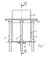
- Figure 1 shows a side view of a reconnaissance and sighting device according to the invention intended to be mounted in the roof or the turret of an armoured vehicle or the like.
- Figure 2 shows a vertical cross-section B-B through the reconnaissance and sighting device according to Figure 1 and where the elevation unit and the protective sleeve have been omitted.
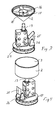
- Figure 3 shows in perspective view an example of how components comprised in the reconnaissance and sighting device according to invention can be arranged.
- Figure 4 shows in perspective view the arrangement according to Figure 3 in a second position and supplemented by a window.
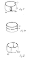
- Figure 5 shows an alternative window embodiment that can be comprised in the reconnaissance and sighting device according to the invention.
- Figures 6a and 6b show two different examples of ballistic shield that can be comprised in the reconnaissance and sighting device according to the invention.
- The reconnaissance and sighting device shown in Figure 1 is essentially contained in a circular cylindrical casing 1 with an outer surface forming a circular
cylindrical window 2 in the top part and a flatcircular window 3 covering the upper end of the cylindrical casing. Figure 1 shows asplinter shield 41 that covers thewindow 2. For thereference numerals bottom plate 4 that can be moved alongparallel rods drive device 9, not shown in greater detail, the upper part of the casing can be raised up through the mounting plate to the end position shown in Figure 1. In a second end position, the upper part of the casing 1 can be lowered down into a protected position below the mounting plate 8. - The construction of the reconnaissance and sighting device will now be described in greater detail with reference to Figure 2. A
cone 10 is arranged in the upper part of the casing. In an alternative embodiment, the cone can be replaced by another suitable rotationally-symmetrical body. The cone is inverted, with its vertex 11 pointing downwards. The outer surface of the cone is covered with a radiation-reflectingmaterial 12 forming a conical mirror. In thecone 10, there is acavity 16 with anopening 17 towards the base of the cone. A first electro-optical sensor device 13 is arranged on a production of the axis of the cone beyond the vertex 11, with its optical axis coinciding with the production of the axis of rotation of the cone beyond the vertex. Thesensor device 13 takes in the light from the surroundings through 360° and at an angle to the horizontal plane that is determined by the field of vision of the sensor device and the vertex angle of theconical mirror 12. In the figure, the area from which the sensor device takes in light is delimited by dotted-dashedlines 14 and 15. - In order to provide supplementary optical information from the upper part of the space, the reconnaissance and sighting device is provided with an additional electro-
optical sensor device 18, called a third sensor device in the following, arranged in thecavity 16 of thecone 10 and directed towards theopening 17. The field of vision for thisthird sensor device 18, delimited bylines - A second electro-
optical sensor device 21 is arranged in association with the first electro-optical sensor device 13, which is mounted on the production of the axis of thecone 10 beyond its vertex. In the embodiment shown, the second sensor device comprises aninfrared sensor 22 and a combined laser transmitter andlaser receiver 23, all of which have their optical axes aligned with an imaginary radius of the reflectingsurface 12 of the cone. Thesensors carousel 24 with an axis of rotation that is coaxial with the axis of symmetry of thecone 10. In the sensor device, there is also an optically-reflectingdevice 25 that can be tilted. Thedevice 25 that can be tilted is suspended in acradle 26. Thedevice 25 comprises asemitransparent surface 27 and a reflectingsurface 28 separated by a light-transmittinglayer 29. Thesemitransparent surface 27 reflects radiation within the infrared frequency range and transmits laser light, while the reflectingsurface 28 reflects light within the laser wavelengths used. Examples of possible beam paths between the second sensor device and the surroundings of the reconnaissance and sighting device are shown by means ofbroken lines - By means of the reconnaissance and sighting device described above, a broad perception of the surroundings is provided, based primarily on the first and third sensor devices, while the second sensor device provides more specific information about a specific point. At the same time, the possibility that the second sensor device can be utilized for sweeping round a whole revolution is not excluded. The information that the sensor devices collect is image-processed in real time and presented to the operators in a way that can be understood. Methods for image processing are already known and are therefore not described here in greater detail.
- Figures 3 and 4 show vital parts comprised in the reconnaissance and sighting device. Components that are to be found in the description of Figures 1 and 2 have been given the same reference numerals and are therefore not described here. The principal differences between Figures 3 and 4 are that the
carousel 24 is shown in two different positions that differ by almost 180° in angle of rotation. Another difference is that thewindow parts cone 10 shown in Figure 3. - Figure 5 shows an alternative embodiment of the window that allows radiation to pass through while at the same time protecting the equipment inside against dirt, moisture and ice. The
cylindrical window 2 around thecone 10 has been provided byplate glass 39 in aframe 40. By arranging thewindow 2 so that it rotates around the axis of symmetry of thecone 10 at the same speed and in the same direction as thesecond sensor device 21 is arranged to rotate around the same axis of symmetry, it can be ensured that the plate glass is always utilized for the beam path associated with the second sensor device. By meeting the high requirements for the window within a limited area in this way, while at the same time meeting lower requirements for other parts of the window, the cost of the window can be kept down or alternatively the performance can be improved. Alternatively, the part of the window that is utilized by the second sensor device can be manufactured to extra high specifications in comparison with other larger parts of the window. The advantages of usingplate glass 39 is that it is easier to achieve high optical performance and a choice of material can be made that is optimized for the second sensor device. - As the reconnaissance and sighting device which has been described above does not have exterior moving parts, any splinter shield can be arranged in the same place and therefore the mechanical construction becomes relatively uncomplicated. The splinter shield can be designed as a tube that is moved out as a sleeve over the reconnaissance and sighting device and in particular its
window 2. A simple variant of the sleeve is shown in Figure 1 and has been given thereference 41. The sleeve is designed in one piece without openings in the outer surface. - Figure 6a shows another embodiment of the
sleeve 41. In this case, the sleeve has been provided with one or more slots 42 that run round the sleeve in a common plane at right angles to the axis of symmetry of the sleeve. The sleeve now permits limited observations to be carried out with little risk of exposure to ballistic damage. - Figure 6b shows an example of an additional embodiment of the sleeve. The
sleeve 41 has been divided into twohalves 43 and 44 that can be moved individually. In this way, the activity can be carried out with full performance in a limited angular space, while at the same time a certain degree of protection from ballistic damage is provided and the signature of the reconnaissance and sensor device is minimized in certain directions. In this connection, it can be pointed out that it is also possible to divide the sleeve into more than two sections that can be moved individually. - For cleaning the reconnaissance and sighting device, wipers and/or a rinsing system can be arranged. As a result of the shape of the reconnaissance and sighting device, the surfaces that are to be cleaned are relatively easy to access both by wiper blade and by rinsing.
- As the reconnaissance and sighting device is essentially cylindrical in shape, the device can suitably be arranged in the roof of the turret of an armoured vehicle in order to be able to be moved out of and withdrawn back into the turret. The withdrawn position gives a minimal signature, while the area of observation is greatly reduced as in principle only the third sensor device which is directed upwards can provide information. The ballistic protection is increased by the turret's existing ballistic shield. In addition, the withdrawn position provides good protection of various types on such occasions when it is not necessary to utilize the reconnaissance and sighting system, for example when the vehicles are in convoy.
- The invention is not limited to the embodiments described above by way of example, but can be modified within the framework of the following claims.
Claims (18)
- Reconnaissance and sighting device comprising a first device for collecting optical information over a large space and a second device for collecting optical information from a specific point in a specific direction, characterized in that the first and the second device are integrated into one unit for simultaneous collection of the optical information.
- Reconnaissance and sighting device according to Claim 1, characterized in that the reconnaissance and sighting device comprises a hollow essentially rotationally-symmetrical tapering body that is open at the broad end and has a mirrored outer surface, which body is common to the first and second device.
- Reconnaissance and sighting device according to Claim 2, characterized in that the rotationally-symmetrical body consists of a hollow cone with an open base and a mirrored outer surface.
- Reconnaissance and sighting device according to Claim 2 or 3, characterized in that a first electro-optical sensor device is arranged with its optical axis on a production of the axis of the tapering body beyond its vertex, in order to be able to take in light from the surroundings through 360° via the mirrored outer surface, which first electro-optical sensor device and also the rotationally-symmetrical tapering body are comprised in the first device.
- Reconnaissance and sighting device according to any one of Claims 2-4, characterized in that a second electro-optical sensor device is arranged in such a way that it can be rotated around the axis of symmetry of the rotationally-symmetrical tapering body, in that a device for changing the direction of light is arranged between the second electro-optical sensor device and the tapering body, whereby a beam path is created between a specific point and the second sensor device via the mirrored outer surface of the tapering body and the device for changing the direction of light, with the second electro-optical sensor device, the rotationally-symmetrical tapering body and the device for changing the direction of light being comprised in the second device.
- Reconnaissance and sighting device according to Claim 5, characterized in that the second sensor device consists of at least two sensors of the same or different types, such as infrared sensors and/or laser sensors.
- Reconnaissance and sighting device according to Claim 5 or 6, characterized in that the device for changing the direction of light consists of an optically-reflecting device that is arranged in such a way that it can be tilted.
- Reconnaissance and sighting device according to Claim 7, characterized in that the optically-reflecting device comprises a first semitransparent surface that reflects radiation within a first frequency range and transmits radiation within a second frequency range and a second reflecting surface that reflects radiation at least within the second frequency range.
- Reconnaissance and sighting device according to any one of the preceding Claims 2-8, characterized in that a third electro-optical sensor device is arranged in the tapering body and is aimed to cover an essentially symmetrical field of vision radiating out from the open end of body.
- Reconnaissance and sighting device according to any one of the preceding Claims 2-9, characterized in that an essentially cylindrical window is arranged to cover the mirrored outer surface of the tapering body.
- Reconnaissance and sighting device according to Claim 10 and Claim 5, characterized in that the cylindrical window is arranged to rotate around the axis of symmetry of the rotationally-symmetrical tapering body at the same speed and in the same direction as the rotation of the second electro-optical sensor device around the same axis of symmetry.
- Reconnaissance and sighting device according to Claim 11 and Claim 5, characterized in that the part of the cylindrical window which is used by the second electro-optical sensor device is manufactured with a higher degree of accuracy than other parts of the cylindrical window.
- Reconnaissance and sighting device according to Claim 11 and Claim 5, characterized in that the part of the cylindrical window which is used by the second electro-optical sensor device consists of plate glass.
- Reconnaissance and sighting device according to any one of the preceding claims, characterized in that a ballistic shield in the form of a tube-shaped sleeve is arranged in such a way that it can be moved out and cover parts of the reconnaissance and sighting device.
- Reconnaissance and sighting device according to Claim 14, characterized in that the tube-shaped sleeve is provided with one or more slots, all running round the sleeve in a plane at right angles to the axis of symmetry of the sleeve.
- Reconnaissance and sighting device according to Claim 14 or 15, characterized in that the tube-shaped sleeve is designed as two or more sections that can be moved individually.
- Reconnaissance and sighting device according to any one of the preceding claims, characterized in that it comprises cleaning devices utilizing rinsing and/or wiping principles.
- Reconnaissance and sighting device according to any one of the preceding claims, characterized in that the reconnaissance and sighting device is arranged to be able to be moved out of and withdrawn beneath a shell, such as the casing on an armoured vehicle.
Applications Claiming Priority (2)
| Application Number | Priority Date | Filing Date | Title |
|---|---|---|---|
| SE0301734A SE524904C2 (en) | 2003-06-16 | 2003-06-16 | Sight and scooping device for e.g. battlefield vehicle, collects optical information from large area and specific point in specific direction at same time via common optical component |
| SE0301734 | 2003-06-16 |
Publications (1)
| Publication Number | Publication Date |
|---|---|
| EP1491847A1 true EP1491847A1 (en) | 2004-12-29 |
Family
ID=29212465
Family Applications (1)
| Application Number | Title | Priority Date | Filing Date |
|---|---|---|---|
| EP20040445066 Withdrawn EP1491847A1 (en) | 2003-06-16 | 2004-06-02 | Reconnaissance and sighting device |
Country Status (2)
| Country | Link |
|---|---|
| EP (1) | EP1491847A1 (en) |
| SE (1) | SE524904C2 (en) |
Cited By (2)
| Publication number | Priority date | Publication date | Assignee | Title |
|---|---|---|---|---|
| WO2010022695A1 (en) * | 2008-08-23 | 2010-03-04 | Krauss-Maffei Wegmann Gmbh & Co. Kg | Protection device for an optical apparatus of a vehicle, in particular of a military vehicle |
| EP2183542B2 (en) † | 2007-08-31 | 2021-06-09 | Rheinmetall Landsysteme GmbH | Lowerable optical adaptor, in particular for a combat vehicle equipped with a weapon |
Citations (5)
| Publication number | Priority date | Publication date | Assignee | Title |
|---|---|---|---|---|
| US3294903A (en) * | 1961-04-19 | 1966-12-27 | Columbia Broadcasting Syst Inc | Electronic reconnaissance systems |
| US4810088A (en) * | 1984-08-16 | 1989-03-07 | Hughes Aircraft Company | Laser rangefinder and thermal imager with enhanced scanning mirror control |
| US5363235A (en) * | 1993-02-10 | 1994-11-08 | Hughes Aircraft Company | Dual field of view multi wavelength sensor |
| WO1999013355A1 (en) * | 1997-09-11 | 1999-03-18 | Raytheon Company | Single aperture thermal imager, direct view, tv sight and laser ranging system subsystems including optics, components, displays, architecture with gps (global positioning sensors) |
| US20020126395A1 (en) * | 2000-03-22 | 2002-09-12 | Sajan Gianchandani | Panoramic image acquisition device |
-
2003
- 2003-06-16 SE SE0301734A patent/SE524904C2/en not_active IP Right Cessation
-
2004
- 2004-06-02 EP EP20040445066 patent/EP1491847A1/en not_active Withdrawn
Patent Citations (5)
| Publication number | Priority date | Publication date | Assignee | Title |
|---|---|---|---|---|
| US3294903A (en) * | 1961-04-19 | 1966-12-27 | Columbia Broadcasting Syst Inc | Electronic reconnaissance systems |
| US4810088A (en) * | 1984-08-16 | 1989-03-07 | Hughes Aircraft Company | Laser rangefinder and thermal imager with enhanced scanning mirror control |
| US5363235A (en) * | 1993-02-10 | 1994-11-08 | Hughes Aircraft Company | Dual field of view multi wavelength sensor |
| WO1999013355A1 (en) * | 1997-09-11 | 1999-03-18 | Raytheon Company | Single aperture thermal imager, direct view, tv sight and laser ranging system subsystems including optics, components, displays, architecture with gps (global positioning sensors) |
| US20020126395A1 (en) * | 2000-03-22 | 2002-09-12 | Sajan Gianchandani | Panoramic image acquisition device |
Cited By (2)
| Publication number | Priority date | Publication date | Assignee | Title |
|---|---|---|---|---|
| EP2183542B2 (en) † | 2007-08-31 | 2021-06-09 | Rheinmetall Landsysteme GmbH | Lowerable optical adaptor, in particular for a combat vehicle equipped with a weapon |
| WO2010022695A1 (en) * | 2008-08-23 | 2010-03-04 | Krauss-Maffei Wegmann Gmbh & Co. Kg | Protection device for an optical apparatus of a vehicle, in particular of a military vehicle |
Also Published As
| Publication number | Publication date |
|---|---|
| SE0301734D0 (en) | 2003-06-16 |
| SE0301734L (en) | 2004-10-19 |
| SE524904C2 (en) | 2004-10-19 |
Similar Documents
| Publication | Publication Date | Title |
|---|---|---|
| US7982662B2 (en) | Scanning array for obstacle detection and collision avoidance | |
| EP3295115B1 (en) | Optical waveguide coude path for gimbaled systems | |
| US7221505B2 (en) | Panoramic field of view acquiring and displaying system | |
| US9188481B2 (en) | Sensing/emitting apparatus, system and method | |
| US4626905A (en) | Panoramic view apparatus | |
| US10057509B2 (en) | Multiple-sensor imaging system | |
| KR100477256B1 (en) | observation or sighting system | |
| JP2021099314A (en) | Lidar sensor | |
| CN109452257A (en) | A kind of airport flying bird visual monitoring and drive linked system | |
| US6129307A (en) | Stabilized optical gimbal assembly | |
| WO1998003882B1 (en) | Observation or sighting system | |
| EP1547115B1 (en) | Optical imaging system having a field-of-regard | |
| EP1491847A1 (en) | Reconnaissance and sighting device | |
| US5943163A (en) | Optical and infrared periscope | |
| AU2004237193C1 (en) | Gimbal assembly for optical imaging system | |
| DE19927502A1 (en) | Distance sensing arrangement for motor vehicle has essentially rod-shaped housing that is transparent, at least in scanner's wavelength range, in region of laser scanner light beam outlet | |
| WO2013028939A2 (en) | A modular multi-use thermal imaging system | |
| US4434702A (en) | Telescoping periscope | |
| RU2769043C2 (en) | Optoelectronic system for platform and corresponding platform | |
| US8605349B2 (en) | Large area surveillance scanning optical system | |
| GB2146137A (en) | Optical-mechanical scanning system switched between two inputs | |
| US8087197B2 (en) | Method and apparatus for influencing reflections from an optical surface | |
| EP3882161B1 (en) | Helicopter search light and method of operating a helicopter search light | |
| US20220381886A1 (en) | Detection system and method using a line detector | |
| EP4363786A1 (en) | Observing device comprising independent optical and optronic channels and vehicle equipped with such a device |
Legal Events
| Date | Code | Title | Description |
|---|---|---|---|
| PUAI | Public reference made under article 153(3) epc to a published international application that has entered the european phase |
Free format text: ORIGINAL CODE: 0009012 |
|
| AK | Designated contracting states |
Kind code of ref document: A1 Designated state(s): AT BE BG CH CY CZ DE DK EE ES FI FR GB GR HU IE IT LI LU MC NL PL PT RO SE SI SK TR |
|
| AX | Request for extension of the european patent |
Extension state: AL HR LT LV MK |
|
| 17P | Request for examination filed |
Effective date: 20050601 |
|
| AKX | Designation fees paid |
Designated state(s): AT BE BG CH CY CZ DE DK EE ES FI FR GB GR HU IE IT LI LU MC NL PL PT RO SE SI SK TR |
|
| GRAP | Despatch of communication of intention to grant a patent |
Free format text: ORIGINAL CODE: EPIDOSNIGR1 |
|
| STAA | Information on the status of an ep patent application or granted ep patent |
Free format text: STATUS: THE APPLICATION IS DEEMED TO BE WITHDRAWN |
|
| 18D | Application deemed to be withdrawn |
Effective date: 20071023 |