EP1491748A2 - Control apparatus of internal combustion engine with turbocharger - Google Patents
Control apparatus of internal combustion engine with turbocharger Download PDFInfo
- Publication number
- EP1491748A2 EP1491748A2 EP20040014986 EP04014986A EP1491748A2 EP 1491748 A2 EP1491748 A2 EP 1491748A2 EP 20040014986 EP20040014986 EP 20040014986 EP 04014986 A EP04014986 A EP 04014986A EP 1491748 A2 EP1491748 A2 EP 1491748A2
- Authority
- EP
- European Patent Office
- Prior art keywords
- internal combustion
- combustion engine
- exhaust gas
- temperature
- output
- Prior art date
- Legal status (The legal status is an assumption and is not a legal conclusion. Google has not performed a legal analysis and makes no representation as to the accuracy of the status listed.)
- Granted
Links
Images


Classifications
-
- F—MECHANICAL ENGINEERING; LIGHTING; HEATING; WEAPONS; BLASTING
- F02—COMBUSTION ENGINES; HOT-GAS OR COMBUSTION-PRODUCT ENGINE PLANTS
- F02D—CONTROLLING COMBUSTION ENGINES
- F02D41/00—Electrical control of supply of combustible mixture or its constituents
- F02D41/02—Circuit arrangements for generating control signals
- F02D41/14—Introducing closed-loop corrections
- F02D41/1497—With detection of the mechanical response of the engine
-
- F—MECHANICAL ENGINEERING; LIGHTING; HEATING; WEAPONS; BLASTING
- F02—COMBUSTION ENGINES; HOT-GAS OR COMBUSTION-PRODUCT ENGINE PLANTS
- F02D—CONTROLLING COMBUSTION ENGINES
- F02D41/00—Electrical control of supply of combustible mixture or its constituents
- F02D41/0002—Controlling intake air
- F02D41/0007—Controlling intake air for control of turbo-charged or super-charged engines
-
- F—MECHANICAL ENGINEERING; LIGHTING; HEATING; WEAPONS; BLASTING
- F02—COMBUSTION ENGINES; HOT-GAS OR COMBUSTION-PRODUCT ENGINE PLANTS
- F02D—CONTROLLING COMBUSTION ENGINES
- F02D41/00—Electrical control of supply of combustible mixture or its constituents
- F02D41/02—Circuit arrangements for generating control signals
- F02D41/021—Introducing corrections for particular conditions exterior to the engine
- F02D41/0235—Introducing corrections for particular conditions exterior to the engine in relation with the state of the exhaust gas treating apparatus
-
- F—MECHANICAL ENGINEERING; LIGHTING; HEATING; WEAPONS; BLASTING
- F02—COMBUSTION ENGINES; HOT-GAS OR COMBUSTION-PRODUCT ENGINE PLANTS
- F02D—CONTROLLING COMBUSTION ENGINES
- F02D2200/00—Input parameters for engine control
- F02D2200/02—Input parameters for engine control the parameters being related to the engine
- F02D2200/08—Exhaust gas treatment apparatus parameters
- F02D2200/0802—Temperature of the exhaust gas treatment apparatus
-
- F—MECHANICAL ENGINEERING; LIGHTING; HEATING; WEAPONS; BLASTING
- F02—COMBUSTION ENGINES; HOT-GAS OR COMBUSTION-PRODUCT ENGINE PLANTS
- F02D—CONTROLLING COMBUSTION ENGINES
- F02D2250/00—Engine control related to specific problems or objectives
- F02D2250/18—Control of the engine output torque
-
- F—MECHANICAL ENGINEERING; LIGHTING; HEATING; WEAPONS; BLASTING
- F02—COMBUSTION ENGINES; HOT-GAS OR COMBUSTION-PRODUCT ENGINE PLANTS
- F02D—CONTROLLING COMBUSTION ENGINES
- F02D41/00—Electrical control of supply of combustible mixture or its constituents
- F02D41/02—Circuit arrangements for generating control signals
- F02D41/14—Introducing closed-loop corrections
- F02D41/1438—Introducing closed-loop corrections using means for determining characteristics of the combustion gases; Sensors therefor
- F02D41/1444—Introducing closed-loop corrections using means for determining characteristics of the combustion gases; Sensors therefor characterised by the characteristics of the combustion gases
- F02D41/1446—Introducing closed-loop corrections using means for determining characteristics of the combustion gases; Sensors therefor characterised by the characteristics of the combustion gases the characteristics being exhaust temperatures
-
- Y—GENERAL TAGGING OF NEW TECHNOLOGICAL DEVELOPMENTS; GENERAL TAGGING OF CROSS-SECTIONAL TECHNOLOGIES SPANNING OVER SEVERAL SECTIONS OF THE IPC; TECHNICAL SUBJECTS COVERED BY FORMER USPC CROSS-REFERENCE ART COLLECTIONS [XRACs] AND DIGESTS
- Y02—TECHNOLOGIES OR APPLICATIONS FOR MITIGATION OR ADAPTATION AGAINST CLIMATE CHANGE
- Y02T—CLIMATE CHANGE MITIGATION TECHNOLOGIES RELATED TO TRANSPORTATION
- Y02T10/00—Road transport of goods or passengers
- Y02T10/10—Internal combustion engine [ICE] based vehicles
- Y02T10/12—Improving ICE efficiencies
Definitions
- the present invention relates to a control apparatus of an internal combustion engine provided with a turbocharger for supercharging intake air by utilizing exhaust gas energy.
- a preferable temperature range exists, for example, in a particulate filter for trapping particulate matters or an oxygen concentration sensor to be used for detecting an air fuel ratio. Accordingly, the same problem is generated by operating an amount of the exhaust gas energy recovered by the turbocharger for controlling the temperatures.
- an object of the present invention is to provide a control apparatus of an internal combustion engine with a turbocharger, which can stabilize an output of the internal combustion engine while changing an amount of exhaust gas energy recovered by the turbocharger in correspondence to a temperature adjustment state of a subject to be adjusted a temperature such as a catalyst or the like arranged in an exhaust gas passage in a downstream side of the turbocharger.
- a control apparatus to be applied to an internal combustion engine which is provided with a turbocharger for supercharging intake air by utilizing exhaust gas energy, and a recovered energy amount adjusting device for adjusting an energy amount recovered from the exhaust gas by the turbocharger, comprising an operation control device for controlling an operation of the recovered energy amount adj usting device in such a manner that the recovered energy amount is adjusted in correspondence to a temperature adjusting state of a temperature adj usted subj ect arranged in an exhaust gas passage in a downstream side of the turbocharger; and an output adjusting device for adjusting an output of the internal combustion engine so as to compensate for a change of an output of the internal combustion engine which is expected in accordance with an adjustment of the recovered energy in correspondence to the temperature adjustment state by the operation control device.
- the output adjusting device adjusts the output in correspondence to the adjustment so as to inhibit the change. Accordingly, it is possible to stabilize the output of the internal combustion engine.
- the temperature adj usted subj ect includes various devices which are arranged in the exhaust gas passage and require a temperature adjustment, such as an oxygen concentration sensor and a catalyst, which exert a function in a predetermined temperature range, a particulate filter and an occlusion-reduction type NOx catalyst in which a function is reproduced by heating, and the like.
- the recovered energy adjusting device it is possible to apply various devices including a device capable of changing a flow rate or a flow speed of the exhaust gas introduced to the exhaust gas turbine of the turbocharger so as to adjust the amount of the recovered energy and a device capable of changing a load applied to a rotating shaft of the turbocharger, such as a bypass passage for bypassing the exhaust gas flowing into the exhaust gas turbine of the turbocharger and a bypass valve for adjusting the flow rate of the exhaust gas passing through the bypass passage, a variable nozzle for changing a cross sectional area of an exhaust gas flow inlet of the exhaust gas turbocharger so as to change a flow speed of the exhaust gas introduced to the exhaust gas turbine, an operation connected to the rotating shaft of the turbocharger so as to function as an electric motor or a power generator in correspondence to an operational state of the internal combustion engine and generating an electric power on the basis of the exhaust gas energy recovered by the exhaust gas turbine, and the like.
- a concept "compensation” means to change the output in a direction of canceling the change in the output of the internal combustion engine which is expected in correspondence to the adj ustment of the recovered energy amount, and includes completely canceling the output change, and reducing the change amount of the output.
- the output adjusting device may adjust the output of the internal combustion engine by changing a rotation speed of the internal combustion engine.
- the output of the internal combustion engine may be adjusted by changing either of a torque and the rotation speed of the internal combustion engine.
- the output of the internal combustion engine may be adjusted by changing either of a fuel amount and intake air amount supplied to the internal combustion engine, and may be adj usted by changing a working angle of a valve in the case of the internal combustion engine having a variable valve moving mechanism.
- the rotation speed of the internal combustion engine can be changed by adjusting a gear ratio of the transmission.
- a high-temperature exhaust gas is fed to the temperature adjusted subject in a downstream side of the turbocharger by reducing the recovered energy amount of the turbocharger.
- a supercharging pressure of the intake air is lowered and a torque of the internal combustion engine is urged to be lowered in correspondence to the reduction of the recovered energy amount, it is possible to compensate the reduction in the output by changing the rotation speed to a high rotation side.
- a retention time of the combustion gas within the cylinder becomes shorter, and an after burning tendency is generated, so that an exhaust gas loss is increased and an exhaust gas temperature is increased. Accordingly, it is possible to promote heating the temperature adj usted subj ect in correspondence to the increase of the exhaust gas temperature.
- the recovered energy amount of the turbocharger is increased on the contrary to the case of heating.
- the torque of the internal combustion engine is urged to be increased.
- the exhaust gas loss is reduced, and the exhaust gas temperature is lowered. Accordingly, it is possible to promote cooling the temperature adjusted subject.
- the control apparatus in accordance with the present invention may be provided with an exhaust gas purifying device in which a function is reproduced by being heated to a predetermined temperature or more as the temperature adjusted subject, the operation control device may reduce the recovered energy amount in the case of reproducing the function of the exhaust gas purifying device, and the output adjusting device may increase an output of the internal combustion engine so as to compensate the reduction in the output of the internal combustion engine which is expected in accordance with an adjustment for reducing the recovered energy amount which the operation control device executes at a time of reproducing the function of the exhaust gas purifying device. Since the reduction in the output of the internal combustion engine generated in the case of heating the exhaust gas purifying device is compensated by the output adj usting device as mentioned above, it is possible to stabilize the output of the internal combustion engine.
- the control apparatus in accordance with the present invention may be provided with a temperature acquiring device for acquiring the temperature of the temperature adj usted subj ect, the operation control device may adjust the recovered energy amount on the basis of the temperature which is acquired by the temperature acquiring device, and the output adjusting device may adjust the output of the internal combustion engine so as to compensate the change in the output of the internal combustion engine which is expected in accordance with the adjustment of the recovered energy amount by the operation control device on the basis of the temperature acquiredby the temperature acquiring device. It is possible to prevent a superheating or a supercooling so as to maintain the temperature adjusted subject within a proper temperature range, by adjusting the recovered energy amount on the basis of the temperature acquired by the temperature acquiring device as mentioned above.
- the internal combustion engine may be provided with a bypass passage which connects an exhaust gas passage in an upstream side of the turbocharger to an exhaust gas passage in a downstream side of the turbocharger and in an upstream side of the temperature adjusted subject, and with a bypass valve which controls a flow rate of the exhaust gas passing through the bypass passage, and the operation control device may control an operation of the bypass valve so as to serve as the recovered energy amount adjusting device. It is possible to change the flow rate of the exhaust gas introduced to the turbocharger so as to adj ust the recovered energy amount, by arranging the bypass passage and adjusting the flow rate by means of the bypass valve as mentioned above.
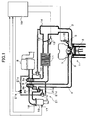
- FIG. 1 shows a main portion of an internal combustion engine to which a control apparatus in accordance with the present invention is applied.
- An internal combustion engine 1 is structured as a four stroke spark ignition type gasoline engine which is used as a traveling power source of a motor vehicle.
- the internal combustion engine 1 is provided with an intake passage 3 for taking intake air into a combustion chamber 2, an exhaust gas passage 4 for introducing an exhaust gas from the combustion chamber 2 to a predetermined exhausting position, an intake valve 5 and an exhaust gas valve 6 for opening and closing the passages 3 and 4 with respect to the combustion chamber 2, and an ignition plug 7 for igniting an air-fuel mixture introduced into the combustion chamber 2.
- the intake passage 3 is provided with an air filter 8 for filtering the intake air, a compressor 9a of a turbocharger 9 supercharging the intake air by utilizing exhaust gas energy, a supercharging pressure control valve 10 connecting an upstream side of the compressor 9a to the intake passage 3 in a downstream side in the case that the supercharging pressure is more than a predetermined pressure, an inter-cooler 11 cooling the intake air, a throttle valve 12 for adjusting an amount of the intake air, an idle speed control valve 13 arranged in parallel to the throttle valve 12 and adjusting an amount of the intake air bypassing the throttle valve 12, a surge tank 14 inhibiting the intake air frompulsating, and an injector 15 supplying the fuel to the intake air for preparing the air-fuel mixture.
- an air filter 8 for filtering the intake air
- a compressor 9a of a turbocharger 9 supercharging the intake air by utilizing exhaust gas energy
- a supercharging pressure control valve 10 connecting an upstream side of the compressor 9a to the intake passage 3 in a downstream side in the
- the exhaust gas passage 4 is provided with a turbine 9b of the turbocharger 9, a catalyst 16 serving as an exhaust gas purifying device, a temperature sensor 17 serving as a temperature acquiring device for outputting a signal in correspondence to a temperature of the catalyst 16, and an air fuel ratio sensor 18 outputting a signal in correspondence to an air fuel ration of the exhaust gas.
- An operating state of the internal combustion engine 1 is controlled by an engine control unit (ECU) 19.
- the ECU 19 is structured as a computer obtained by combining peripheral devices such as a microprocessor and ROM, RAM and the like which are required for operatingthemicroprocessor.
- the ECU 19 carries out an arithmetical operation, for example, of a fuel injection amount on the basis of the operating state of the internal combustion engine 1, and controls an operation of the injector 15 such that the arithmetically operated amount of fuel is supplied at a predetermined timing.
- the exhaust gas passage 4 is provided with a bypass passage 20 connecting the exhaust gas passage 4 in an upstream side of the turbine 9b to the exhaust gas passage 4 in a downstream side of the turbine 9b and in an upstream side of the catalyst 16, and a waste gate valve 21 serving as a bypass valve controlling a flow rate of the exhaust gas passing through the bypass passage 20.
- the waste gate valve 21 is constituted by a valve body 21a and an actuator 21b driving the valve body 21a by utilizing a pressure of the intake air introduced into therein.
- the actuator 21b and the intake passage 3 in the upstream side and in the downstream side of the compressor 9a are connected by an intake air discharging passage 21c and an intake air introducing passage 21d.
- the intake air discharging passage 21c is provided with a pressure adjusting valve 21e connecting the actuator 21b to the intake passage 3 in the upstream side of the compressor 9a and shutting off the connection so as to adjust the pressure of the intake air introduced into the actuator 21b.
- the actuator 21b operates the valve body 21a in correspondence to the pressure of the intake air introduced into the actuator 21b.
- the actuator 21b opens the valve body 21a so as to introduce the exhaust gas to the bypass passage 20, thereby restricting the output of the turbine 9b.
- the actuator 21b closes the valve body 21a so as to flow all of the exhaust gas into the turbine 9b, thereby increasing the output of the turbine 9b.
- the waste gate valve 21 serves as a recovered energy amount adjusting device.
- the pressure adjusting valve 21e can control the pressure of the intake air within the actuator 21b by being operated so as to open and close. For example, in the case that the pressure adjusting valve 21e is in an open state, the pressure adjusting valve 21e returns the intake air introduced into the actuator 21b to the intake passage 3, thereby lowering the pressure of the intake air within the actuator 21b. On the other hand, in the case that the pressure adjusting valve 21e is in a closed state, the actuator adjusting valve 21e shuts off the connection between the actuator 21b and the intake passage 3 so as to increase the pressure of the intake air within the actuator 21b.
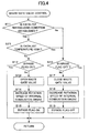
- FIG. 2 is a flow chart showing a waste gate valve control routine which the ECU 19 executes for controlling the pressure adjusting valve 21e.
- the ECU 19 serves as an operation control device by executing the routine in FIG. 2. Further, in the routine in FIG. 2, the ECU 19 controls, for example, a transmission (not shown) to a low speed gear side in correspondence to the operation of the pressure adjusting valve 21e, thereby changing the rotation speed of the internal combustion engine 1. In accordance with this control, the ECU 19 serves as an output adjusting device.
- the routine in FIG. 2 is executed repeatedly at a predetermined cycle during the operation of the internal combustion engine 1.
- the ECU 19 first determines in step S11 whether or not a reproducing condition for the catalyst 16 is established. For example, in the case that an occlusion-reduction type NOx catalyst is employed as the catalyst 16, since the catalyst 16 is poisoned by a sulfur content (S), the function thereof is reproduced by heating the catalyst 16.
- the condition executing the reproduction is determined by estimating an amount of the S flowing into the catalyst 16 based on an amount of the fuel supplied by the injector 15. Further, in the case that an accumulation of the estimated values is more than a predetermined value, it is determined that the reproducing condition is established. In this case, the accumulation of the estimated values is reset in the case that the function reproducing process is executed.
- the ECU 19 goes to step S12 and determines whether or not a bypass flag for determining whether or not the valve body 21a is open is in an on state indicating the open. In the case that the ECU 19 determines that the bypass flag is in the on state, this time control routine is terminated. It is possible to show a state of the valve body 21a to the other control routines controlling the operation of the valve body 21a, by the bypass flag.
- step S13 the ECU 19 determines that the bypass flag is not in the on state
- the ECU 19 goes to step S13 and controls the operation of the pressure adjusting valve 21e so as to open the valve body 21a.
- step S14 the ECU 19 changes the transmission to a low speed gear side so as to compensate the reduction in the output of the internal combustion engine 1 expected by opening the valve body 21a, thereby increas ing the rotation speed of the internal combustion engine 1.
- step S15 the ECU 19 sets the bypass flag to the on state, and thereafter terminates this time control routine.
- step S11 the ECU 19 determines in step S11 that the reproducing condition is not established
- step S16 determines whether or not the bypass flag is in an off state.
- the ECU 19 terminates this time control routine.
- step S17 the ECU 19 goes to step S17 and controls the operation of the pressure adjusting valve 21e so as to close the valve body 21a.
- step S18 the ECU 19 changes the transmission to a high speed gear side so as to compensate the increase in the output of the internal combustion engine 1 expected by closing the valve body 21a, thereby reducing the rotation speed of the internal combustion engine 1.
- step S19 the ECU 19 sets the bypass flag to the off state, and thereafter finishes this time control routine.
- FIG. 3 shows an example of an output adjustment of the internal combustion engine 1 which the ECU 19 carries out in the case of operating the valve body 21a in accordance with the control routine in FIG. 2.
- FIG. 3 shows an example of a change in an output and an exhaust gas temperature in the case of setting the torque and the rotation speed of the internal combustion engine 1 to parameters.
- Reference symbols P1 to P3 in FIG. 3 denote constant output lines in the case of changing the torque and the rotation speed
- reference symbols T1 to T3 denote constant exhaust gas temperature lines in the case of changing the torque and the rotation speed, respectively.
- the output is compensated by increasing the rotation speed of the internal combustion engine 1.
- the torque of the internal combustion engine 1 is lowered on the basis of the opening of the valve body 21a in step 13 in FIG. 2, and it is expected that the internal combustion engine 1 will be changed to an operating state at a point A' in FIG. 3 in accordance with the reduction. Since the operating state is changed to a point P1, the output of the internal combustion engine 1 urged to be lowered.
- the ECU 19 increases the rotation speed of the internal combustion engine 1 for the purpose of compensating the reduction in the output in step S14, and changes the operating state to a point B in FIG. 3.
- the operating state of the internal combustion engine 1 is kept on the same constant output line P2 as that of the point A in correspondence to the increase in the rotation speed, and the reduction in the output can be inhibited. Further, as is apparent from FIG. 3, the exhaust gas temperature is increased in accordance with the increase in the rotation speed.
- the output is compensated by reducing the rotation speed of the internal combustion engine 1.
- the torque of the internal combustion engine 1 is increased in correspondence to the closing of the valve body 21a in step 17 in FIG. 2, and it is expected that the internal combustion engine 1 will be changed to an operating state at a point B' in FIG. 3 in accordance with the increase. Since the operating state is changed to a point P3, the output of the internal combustion engine 1 is urged to be increased.
- the ECU 19 reduces the rotation speed of the internal combustion engine 1 for the purpose of compensating the increase in the output in step S18, and changes the operating state to the point A in FIG. 3.
- the operating state of the internal combustion engine 1 is kept on the same constant output line P2 as that of the point B in accordance with the reduction in the rotation speed, and the increase in the output can be inhibited. Further, as is apparent from FIG. 3, the exhaust gas temperature is lowered in accordance with the reduction in the rotation speed.
- control routine for serving the ECU 19 as the operation control device and the output adjusting device with reference to FIG. 4.
- the routine is also executed repeatedly at a predetermined cycle during the operation of the internal combustion engine 1.
- the same reference symbols are attached to the same processes as those in FIG. 2, and a description thereof will be omitted.
- step S11 determines in step S11 that the reproducing condition is established
- step S21 determines whether or not the temperature of the catalyst 16 is high. Whether or not the temperature is high can be determined, for example, on the basis of whether or not the temperature acquired by the temperature sensor 17 is higher than a predetermined temperature.
- the ECU 19 determines that the temperature of the catalyst 16 is not high
- step S12 carries out the same process as that in FIG. 2.
- the ECU 19 determines that the temperature of the catalyst 16 is high or in the case that the ECU 19 determines in step S11 that the reproducing condition is not established, the ECU 19 goes to step S16 and thereunder carries out the same process as that in FIG. 2.
- the present invention is not limited to the embodiments mentioned above, and can be carried out in accordance with various aspects.
- the internal combustion engine is not limited to the gasoline engine, and the present invention can be applied to a diesel engine.
- the exhaust gas purifying device is not limited to the catalyst, and it is possible to various devices such as a particulate filter or the like, which can reproduce its function by being heated.
- a continuously variable transmission is preferably applied to the transmission in accordance with the present invention.
- the rotation speed of the internal combustion engine can be also adjusted by changing the intake air amount or the fuel injection amount.
- the device for adjusting the rotation speedof the internal combustion engine is not limited to the transmission, and it is possible to utilize, for example, a throttle valve or an injector.
- the control apparatus in accordance with the present invention can be applied to a so-called hybrid vehicle in which a motor generator serving as an electric motor and a power generator and the internal combustion engine are mounted as the power source.
Abstract
Description
- The present invention relates to a control apparatus of an internal combustion engine provided with a turbocharger for supercharging intake air by utilizing exhaust gas energy.
- In an internal combustion engine which is provided with an exhaust gas turbine of an exhaust gas turbocharger and a catalyst in an exhaust gas passage, and is provided with a bypass passage introducing an exhaust gas to the catalyst while bypassing the exhaust gas turbine, and with a bypass valve for controlling an exhaust gas flow rate in the bypass passage, there has been proposed a technique in which the exhaust gas is introduced from a part of cylinders through the bypass passage to the catalyst at a time of warming up the catalyst, thereby intending an early activation of the catalyst (refer to JP 11-148339 A. In addition, there are publications of JP H06-294318 A, JP H02-286817 A and JP 2001-107722 A as documents relevant to the present invention.
- In the internal combustion engine provided with the turbocharger for supercharging the intake air by utilizing the exhaust gas energy, in the case that the flow rate of the exhaust gas introduced to the turbocharger is changed by operating the bypass valve, an exhaust gas energy amount which the turbocharger recovers is changed according to the change of the flow rate, and a supercharging pressure of the intake air is also changed. The change in the supercharging pressure exerts an influence to a torque of the internal combustion engine, and changes an output of the internal combustion engine.
- However, since the prior art does not take the output change of the internal combustion engine at a time of operating the bypass valve into consideration, there is generated a problem that a drivability is deteriorated in correspondence to the output change of the internal combustion engine.
- Further, besides the catalyst, a preferable temperature range exists, for example, in a particulate filter for trapping particulate matters or an oxygen concentration sensor to be used for detecting an air fuel ratio. Accordingly, the same problem is generated by operating an amount of the exhaust gas energy recovered by the turbocharger for controlling the temperatures.
- Accordingly, an object of the present invention is to provide a control apparatus of an internal combustion engine with a turbocharger, which can stabilize an output of the internal combustion engine while changing an amount of exhaust gas energy recovered by the turbocharger in correspondence to a temperature adjustment state of a subject to be adjusted a temperature such as a catalyst or the like arranged in an exhaust gas passage in a downstream side of the turbocharger.
- To achieve the above object, according to the present invention, there is provided a control apparatus to be applied to an internal combustion engine which is provided with a turbocharger for supercharging intake air by utilizing exhaust gas energy, and a recovered energy amount adjusting device for adjusting an energy amount recovered from the exhaust gas by the turbocharger, comprising an operation control device for controlling an operation of the recovered energy amount adj usting device in such a manner that the recovered energy amount is adjusted in correspondence to a temperature adjusting state of a temperature adj usted subj ect arranged in an exhaust gas passage in a downstream side of the turbocharger; and an output adjusting device for adjusting an output of the internal combustion engine so as to compensate for a change of an output of the internal combustion engine which is expected in accordance with an adjustment of the recovered energy in correspondence to the temperature adjustment state by the operation control device.
- According to the control apparatus of the present invention, in the case that the output of the internal combustion engine is going to be changed due to the adjustment of the recovered energy amount of the turbocharger, the output adjusting device adjusts the output in correspondence to the adjustment so as to inhibit the change. Accordingly, it is possible to stabilize the output of the internal combustion engine.
- In the present invention, the temperature adj usted subj ect includes various devices which are arranged in the exhaust gas passage and require a temperature adjustment, such as an oxygen concentration sensor and a catalyst, which exert a function in a predetermined temperature range, a particulate filter and an occlusion-reduction type NOx catalyst in which a function is reproduced by heating, and the like. As the recovered energy adjusting device, it is possible to apply various devices including a device capable of changing a flow rate or a flow speed of the exhaust gas introduced to the exhaust gas turbine of the turbocharger so as to adjust the amount of the recovered energy and a device capable of changing a load applied to a rotating shaft of the turbocharger, such as a bypass passage for bypassing the exhaust gas flowing into the exhaust gas turbine of the turbocharger and a bypass valve for adjusting the flow rate of the exhaust gas passing through the bypass passage, a variable nozzle for changing a cross sectional area of an exhaust gas flow inlet of the exhaust gas turbocharger so as to change a flow speed of the exhaust gas introduced to the exhaust gas turbine, an operation connected to the rotating shaft of the turbocharger so as to function as an electric motor or a power generator in correspondence to an operational state of the internal combustion engine and generating an electric power on the basis of the exhaust gas energy recovered by the exhaust gas turbine, and the like.
- In the present invention, a concept "compensation" means to change the output in a direction of canceling the change in the output of the internal combustion engine which is expected in correspondence to the adj ustment of the recovered energy amount, and includes completely canceling the output change, and reducing the change amount of the output.
- In the control apparatus in accordance with the present invention, the output adjusting device may adjust the output of the internal combustion engine by changing a rotation speed of the internal combustion engine. The output of the internal combustion engine may be adjusted by changing either of a torque and the rotation speed of the internal combustion engine. The output of the internal combustion engine may be adjusted by changing either of a fuel amount and intake air amount supplied to the internal combustion engine, and may be adj usted by changing a working angle of a valve in the case of the internal combustion engine having a variable valve moving mechanism. Further, in the case that the output shaft of the internal combustion engine is connected to a transmission, the rotation speed of the internal combustion engine can be changed by adjusting a gear ratio of the transmission.
- For example, in the case of heating the temperature adj usted subj ect, a high-temperature exhaust gas is fed to the temperature adjusted subject in a downstream side of the turbocharger by reducing the recovered energy amount of the turbocharger. In this case, since a supercharging pressure of the intake air is lowered and a torque of the internal combustion engine is urged to be lowered in correspondence to the reduction of the recovered energy amount, it is possible to compensate the reduction in the output by changing the rotation speed to a high rotation side. In the case that the rotation speed of the internal combustion engine is changed to the high rotation side, a retention time of the combustion gas within the cylinder becomes shorter, and an after burning tendency is generated, so that an exhaust gas loss is increased and an exhaust gas temperature is increased. Accordingly, it is possible to promote heating the temperature adj usted subj ect in correspondence to the increase of the exhaust gas temperature.
- On the other hand, in the case of cooling the temperature adj usted subj ect, the recovered energy amount of the turbocharger is increased on the contrary to the case of heating. In this case, the torque of the internal combustion engine is urged to be increased. When changing the rotation speed to a low rotation side for compensating the increase in the torque, the exhaust gas loss is reduced, and the exhaust gas temperature is lowered. Accordingly, it is possible to promote cooling the temperature adjusted subject.
- The control apparatus in accordance with the present invention may be provided with an exhaust gas purifying device in which a function is reproduced by being heated to a predetermined temperature or more as the temperature adjusted subject, the operation control device may reduce the recovered energy amount in the case of reproducing the function of the exhaust gas purifying device, and the output adjusting device may increase an output of the internal combustion engine so as to compensate the reduction in the output of the internal combustion engine which is expected in accordance with an adjustment for reducing the recovered energy amount which the operation control device executes at a time of reproducing the function of the exhaust gas purifying device. Since the reduction in the output of the internal combustion engine generated in the case of heating the exhaust gas purifying device is compensated by the output adj usting device as mentioned above, it is possible to stabilize the output of the internal combustion engine.
- The control apparatus in accordance with the present invention may be provided with a temperature acquiring device for acquiring the temperature of the temperature adj usted subj ect, the operation control device may adjust the recovered energy amount on the basis of the temperature which is acquired by the temperature acquiring device, and the output adjusting device may adjust the output of the internal combustion engine so as to compensate the change in the output of the internal combustion engine which is expected in accordance with the adjustment of the recovered energy amount by the operation control device on the basis of the temperature acquiredby the temperature acquiring device. It is possible to prevent a superheating or a supercooling so as to maintain the temperature adjusted subject within a proper temperature range, by adjusting the recovered energy amount on the basis of the temperature acquired by the temperature acquiring device as mentioned above.
- In the control apparatus in accordance with the present invention, the internal combustion engine may be provided with a bypass passage which connects an exhaust gas passage in an upstream side of the turbocharger to an exhaust gas passage in a downstream side of the turbocharger and in an upstream side of the temperature adjusted subject, and with a bypass valve which controls a flow rate of the exhaust gas passing through the bypass passage, and the operation control device may control an operation of the bypass valve so as to serve as the recovered energy amount adjusting device. It is possible to change the flow rate of the exhaust gas introduced to the turbocharger so as to adj ust the recovered energy amount, by arranging the bypass passage and adjusting the flow rate by means of the bypass valve as mentioned above.
-
- FIG. 1 is a view showing a main portion of an internal combustion engine to which a control apparatus in accordance with the present invention is applied;
- FIG. 2 is a flow chart showing a waste gate valve control routine executed by an ECU in FIG. 1;
- FIG. 3 is a view showing an example of a change in an output and an exhaust gas temperature by setting a rotation speed and a torque of an internal combustion engine 1 to a parameter; and
- FIG. 4 is a flow chart showing another waste gate valve control routine executed by the ECU in FIG. 1.
- FIG. 1 shows a main portion of an internal combustion engine to which a control apparatus in accordance with the present invention is applied. An internal combustion engine 1 is structured as a four stroke spark ignition type gasoline engine which is used as a traveling power source of a motor vehicle. As is well known, the internal combustion engine 1 is provided with an
intake passage 3 for taking intake air into acombustion chamber 2, an exhaust gas passage 4 for introducing an exhaust gas from thecombustion chamber 2 to a predetermined exhausting position, anintake valve 5 and anexhaust gas valve 6 for opening and closing thepassages 3 and 4 with respect to thecombustion chamber 2, and anignition plug 7 for igniting an air-fuel mixture introduced into thecombustion chamber 2. Theintake passage 3 is provided with anair filter 8 for filtering the intake air, acompressor 9a of aturbocharger 9 supercharging the intake air by utilizing exhaust gas energy, a superchargingpressure control valve 10 connecting an upstream side of thecompressor 9a to theintake passage 3 in a downstream side in the case that the supercharging pressure is more than a predetermined pressure, aninter-cooler 11 cooling the intake air, athrottle valve 12 for adjusting an amount of the intake air, an idle speed control valve 13 arranged in parallel to thethrottle valve 12 and adjusting an amount of the intake air bypassing thethrottle valve 12, a surge tank 14 inhibiting the intake air frompulsating, and aninjector 15 supplying the fuel to the intake air for preparing the air-fuel mixture. The exhaust gas passage 4 is provided with aturbine 9b of theturbocharger 9, acatalyst 16 serving as an exhaust gas purifying device, atemperature sensor 17 serving as a temperature acquiring device for outputting a signal in correspondence to a temperature of thecatalyst 16, and an airfuel ratio sensor 18 outputting a signal in correspondence to an air fuel ration of the exhaust gas. - An operating state of the internal combustion engine 1 is controlled by an engine control unit (ECU) 19. The ECU 19 is structured as a computer obtained by combining peripheral devices such as a microprocessor and ROM, RAM and the like which are required for operatingthemicroprocessor. The ECU 19 carries out an arithmetical operation, for example, of a fuel injection amount on the basis of the operating state of the internal combustion engine 1, and controls an operation of the
injector 15 such that the arithmetically operated amount of fuel is supplied at a predetermined timing. - The exhaust gas passage 4 is provided with a
bypass passage 20 connecting the exhaust gas passage 4 in an upstream side of theturbine 9b to the exhaust gas passage 4 in a downstream side of theturbine 9b and in an upstream side of thecatalyst 16, and awaste gate valve 21 serving as a bypass valve controlling a flow rate of the exhaust gas passing through thebypass passage 20. Thewaste gate valve 21 is constituted by avalve body 21a and anactuator 21b driving thevalve body 21a by utilizing a pressure of the intake air introduced into therein. Theactuator 21b and theintake passage 3 in the upstream side and in the downstream side of thecompressor 9a are connected by an intake air discharging passage 21c and an intakeair introducing passage 21d. The intake air discharging passage 21c is provided with apressure adjusting valve 21e connecting theactuator 21b to theintake passage 3 in the upstream side of thecompressor 9a and shutting off the connection so as to adjust the pressure of the intake air introduced into theactuator 21b. - The
actuator 21b operates thevalve body 21a in correspondence to the pressure of the intake air introduced into theactuator 21b. For example, in the case that the pressure of the introduced intake air is high, theactuator 21b opens thevalve body 21a so as to introduce the exhaust gas to thebypass passage 20, thereby restricting the output of theturbine 9b. On the other hand, in the case that the pressure of the introduced intake air is low, theactuator 21b closes thevalve body 21a so as to flow all of the exhaust gas into theturbine 9b, thereby increasing the output of theturbine 9b. On the basis of the operation mentioned above, thewaste gate valve 21 serves as a recovered energy amount adjusting device. - The
pressure adjusting valve 21e can control the pressure of the intake air within theactuator 21b by being operated so as to open and close. For example, in the case that thepressure adjusting valve 21e is in an open state, thepressure adjusting valve 21e returns the intake air introduced into theactuator 21b to theintake passage 3, thereby lowering the pressure of the intake air within theactuator 21b. On the other hand, in the case that thepressure adjusting valve 21e is in a closed state, theactuator adjusting valve 21e shuts off the connection between theactuator 21b and theintake passage 3 so as to increase the pressure of the intake air within theactuator 21b. - An operation of the
pressure adjusting valve 21e is controlled by theECU 19. FIG. 2 is a flow chart showing a waste gate valve control routine which theECU 19 executes for controlling thepressure adjusting valve 21e. The ECU 19 serves as an operation control device by executing the routine in FIG. 2. Further, in the routine in FIG. 2, theECU 19 controls, for example, a transmission (not shown) to a low speed gear side in correspondence to the operation of thepressure adjusting valve 21e, thereby changing the rotation speed of the internal combustion engine 1. In accordance with this control, theECU 19 serves as an output adjusting device. The routine in FIG. 2 is executed repeatedly at a predetermined cycle during the operation of the internal combustion engine 1. - In the control routine in FIG. 2, the
ECU 19 first determines in step S11 whether or not a reproducing condition for thecatalyst 16 is established. For example, in the case that an occlusion-reduction type NOx catalyst is employed as thecatalyst 16, since thecatalyst 16 is poisoned by a sulfur content (S), the function thereof is reproduced by heating thecatalyst 16. The condition executing the reproduction is determined by estimating an amount of the S flowing into thecatalyst 16 based on an amount of the fuel supplied by theinjector 15. Further, in the case that an accumulation of the estimated values is more than a predetermined value, it is determined that the reproducing condition is established. In this case, the accumulation of the estimated values is reset in the case that the function reproducing process is executed. - In the case that the reproducing condition is established, the
ECU 19 goes to step S12 and determines whether or not a bypass flag for determining whether or not thevalve body 21a is open is in an on state indicating the open. In the case that theECU 19 determines that the bypass flag is in the on state, this time control routine is terminated. It is possible to show a state of thevalve body 21a to the other control routines controlling the operation of thevalve body 21a, by the bypass flag. - In the case that the
ECU 19 determines that the bypass flag is not in the on state, theECU 19 goes to step S13 and controls the operation of thepressure adjusting valve 21e so as to open thevalve body 21a. In next step S14, theECU 19 changes the transmission to a low speed gear side so as to compensate the reduction in the output of the internal combustion engine 1 expected by opening thevalve body 21a, thereby increas ing the rotation speed of the internal combustion engine 1. In succeeding step S15, theECU 19 sets the bypass flag to the on state, and thereafter terminates this time control routine. - In the case that the
ECU 19 determines in step S11 that the reproducing condition is not established, theECU 19 goes to step S16 and determines whether or not the bypass flag is in an off state. In the case that theECU 19 determines that the bypass flag is in the off state, theECU 19 terminates this time control routine. On the other hand, in the case that theECU 19 determines that the bypass flag is not in the off state, theECU 19 goes to step S17 and controls the operation of thepressure adjusting valve 21e so as to close thevalve body 21a. In next step S18, theECU 19 changes the transmission to a high speed gear side so as to compensate the increase in the output of the internal combustion engine 1 expected by closing thevalve body 21a, thereby reducing the rotation speed of the internal combustion engine 1. In succeeding step S19, theECU 19 sets the bypass flag to the off state, and thereafter finishes this time control routine. - FIG. 3 shows an example of an output adjustment of the internal combustion engine 1 which the
ECU 19 carries out in the case of operating thevalve body 21a in accordance with the control routine in FIG. 2. FIG. 3 shows an example of a change in an output and an exhaust gas temperature in the case of setting the torque and the rotation speed of the internal combustion engine 1 to parameters. Reference symbols P1 to P3 in FIG. 3 denote constant output lines in the case of changing the torque and the rotation speed, and reference symbols T1 to T3 denote constant exhaust gas temperature lines in the case of changing the torque and the rotation speed, respectively. - In the case of opening the
valve body 21a in the control routine in FIG. 2, the output is compensated by increasing the rotation speed of the internal combustion engine 1. For example, in the case that the internal combustion engine 1 is operated by the torque and the rotation speed (the operating state) at a point A in FIG. 3 before opening thevalve body 21a, the torque of the internal combustion engine 1 is lowered on the basis of the opening of thevalve body 21a in step 13 in FIG. 2, and it is expected that the internal combustion engine 1 will be changed to an operating state at a point A' in FIG. 3 in accordance with the reduction. Since the operating state is changed to a point P1, the output of the internal combustion engine 1 urged to be lowered. TheECU 19 increases the rotation speed of the internal combustion engine 1 for the purpose of compensating the reduction in the output in step S14, and changes the operating state to a point B in FIG. 3. The operating state of the internal combustion engine 1 is kept on the same constant output line P2 as that of the point A in correspondence to the increase in the rotation speed, and the reduction in the output can be inhibited. Further, as is apparent from FIG. 3, the exhaust gas temperature is increased in accordance with the increase in the rotation speed. - On the other hand, in the case of closing the
valve body 21a in the control routine in FIG. 2, the output is compensated by reducing the rotation speed of the internal combustion engine 1. For example, in the case that the internal combustion engine 1 is operated in the operating state at the point B in FIG. 3 before closing thevalve body 21a, the torque of the internal combustion engine 1 is increased in correspondence to the closing of thevalve body 21a instep 17 in FIG. 2, and it is expected that the internal combustion engine 1 will be changed to an operating state at a point B' in FIG. 3 in accordance with the increase. Since the operating state is changed to a point P3, the output of the internal combustion engine 1 is urged to be increased. TheECU 19 reduces the rotation speed of the internal combustion engine 1 for the purpose of compensating the increase in the output in step S18, and changes the operating state to the point A in FIG. 3. The operating state of the internal combustion engine 1 is kept on the same constant output line P2 as that of the point B in accordance with the reduction in the rotation speed, and the increase in the output can be inhibited. Further, as is apparent from FIG. 3, the exhaust gas temperature is lowered in accordance with the reduction in the rotation speed. - As mentioned above, it is possible to suppress the change of the output of the internal combustion engine 1 which is expected in accordance with the operation of the
valve body 21a, while operating thevalve body 21a so as to adjust the temperature of thecatalyst 16, by executing the control routine in FIG. 2. Further, since the output is adjustedby changing the rotation speed of the internal combustion engine 1, it is possible to change the exhaust gas temperature so as to quickly adjust the temperature of thecatalyst 16. - Next, a description will be given of another example of the control routine for serving the
ECU 19 as the operation control device and the output adjusting device with reference to FIG. 4. The routine is also executed repeatedly at a predetermined cycle during the operation of the internal combustion engine 1. In this case, the same reference symbols are attached to the same processes as those in FIG. 2, and a description thereof will be omitted. - In the control routine in FIG. 4, in the case that the
ECU 19 determines in step S11 that the reproducing condition is established, theECU 19 goes to step S21 and determines whether or not the temperature of thecatalyst 16 is high. Whether or not the temperature is high can be determined, for example, on the basis of whether or not the temperature acquired by thetemperature sensor 17 is higher than a predetermined temperature. In the case that theECU 19 determines that the temperature of thecatalyst 16 is not high, theECU 19 goes to step S12, and carries out the same process as that in FIG. 2. On the other hand, in the case that theECU 19 determines that the temperature of thecatalyst 16 is high or in the case that theECU 19 determines in step S11 that the reproducing condition is not established, theECU 19 goes to step S16 and thereunder carries out the same process as that in FIG. 2. - As mentioned above, it is possible to maintain the
catalyst 16 in a proper temperature range so as to prevent thecatalyst 16 from being deteriorated due to the superheat or the like, by controlling the operation of thevalve body 21a on the basis of the temperature acquired by thetemperature sensor 17. - The present invention is not limited to the embodiments mentioned above, and can be carried out in accordance with various aspects. For example, the internal combustion engine is not limited to the gasoline engine, and the present invention can be applied to a diesel engine. The exhaust gas purifying device is not limited to the catalyst, and it is possible to various devices such as a particulate filter or the like, which can reproduce its function by being heated.
- A continuously variable transmission is preferably applied to the transmission in accordance with the present invention. Further, the rotation speed of the internal combustion engine can be also adjusted by changing the intake air amount or the fuel injection amount. Accordingly, the device for adjusting the rotation speedof the internal combustion engine is not limited to the transmission, and it is possible to utilize, for example, a throttle valve or an injector.
- The control apparatus in accordance with the present invention can be applied to a so-called hybrid vehicle in which a motor generator serving as an electric motor and a power generator and the internal combustion engine are mounted as the power source.
- As described above, in accordance with the present invention, since it is possible to compensate the change in the torque of the internal combustion engine which is generated in the case of changing the recovered energy amount of the turbocharger and adjusting the temperature of the temperature adjusted subject, by adjusting the output of the internal combustion engine, it is possible to stably maintain the output of the internal combustion engine. Further, since the output is adjusted by changing the rotation speed of the internal combustion engine, it is possible to change the exhaust gas temperature. Accordingly, it is possible to adjust the temperature of the temperature adjusted subject for a shorter time.
Claims (5)
- A control apparatus to be applied to an internal combustion engine which is provided with a turbocharger (9) for supercharging intake air by utilizing exhaust gas energy, and a recovered energy amount adjusting device (21) for adjusting an energy amount recovered from the exhaust gas by the turbocharger, characterized by comprising:an operation control device (19) for controlling an operation of the recovered energy amount adjusting device in such a manner that the recovered energy amount is adjusted in correspondence to a temperature adjusting state of a temperature adjusted subject (16) arranged in an exhaust gas passage (4) in a downstream side of the turbocharger; andan output adjusting device (19) for adjusting an output of the internal combustion engine so as to compensate for a change of an output of the internal combustion engine which is expected in accordance with an adjustment of the recovered energy in correspondence to the temperature adjustment state by the operation control device.
- The control apparatus of the internal combustion engine with the turbocharger according to claim 1, wherein the output adjusting device adjusts the output of the internal combustion engine by changing a rotation speed of the internal combustion engine.
- The control apparatus of the internal combustion engine with the turbocharger according to claim 1 or 2 , wherein an exhaust gas purifying device (16) in which a function is reproduced by being heated to a predetermined temperature or more is provided as the temperature adj usted subj ect, the operation control device reduces the recovered energy amount in the case of reproducing the function of the exhaust gas purifying device, and the output adjusting device increases the output of the internal combustion engine so as to compensate the reduction in the output of the internal combustion engine which is expected in accordance with an adjustment for reducing the recovered energy amount which the operation control device executes at a time of reproducing the function of the exhaust gas purifying device.
- The control apparatus of the internal combustion engine with the turbocharger according to claim 1 or 2, wherein the control apparatus is provided with a temperature acquiring device (17) for acquiring the temperature of the temperature adjusted subject, the operation control device adjusts the recovered energy amount on the basis of the temperature which is acquired by the temperature acquiring device, and the output adjusting device adjusts the output of the internal combustion engine so as to compensate the change in the output of the internal combustion engine which is expected in accordance with the adj ustment of the recovered energy amount by the operation control device on the basis of the temperature acquired by the temperature acquiring device.
- The control apparatus of the internal combustion engine with the turbocharger according to any one of claims 1 to 4, wherein the internal combustion engine is provided with a bypass passage (20) which connects the exhaust gas passage in an upstream side of the turbocharger to the exhaust gas passage in a downstream side of the turbocharger and in an upstream side of the temperature adjusted subject, and with a bypass valve (21) which controls a flow rate of the exhaust gas passing through the bypass passage, and the operation control device controls an operation of the bypass valve so as to serve as the recovered energy amount adjusting device.
Applications Claiming Priority (2)
| Application Number | Priority Date | Filing Date | Title |
|---|---|---|---|
| JP2003184238 | 2003-06-27 | ||
| JP2003184238A JP2005016459A (en) | 2003-06-27 | 2003-06-27 | Controller of internal combustion engine with supercharger |
Publications (3)
| Publication Number | Publication Date |
|---|---|
| EP1491748A2 true EP1491748A2 (en) | 2004-12-29 |
| EP1491748A3 EP1491748A3 (en) | 2005-03-30 |
| EP1491748B1 EP1491748B1 (en) | 2009-06-10 |
Family
ID=33411129
Family Applications (1)
| Application Number | Title | Priority Date | Filing Date |
|---|---|---|---|
| EP04014986A Expired - Fee Related EP1491748B1 (en) | 2003-06-27 | 2004-06-25 | Control apparatus of internal combustion engine with turbocharger |
Country Status (3)
| Country | Link |
|---|---|
| EP (1) | EP1491748B1 (en) |
| JP (1) | JP2005016459A (en) |
| DE (1) | DE602004021455D1 (en) |
Cited By (6)
| Publication number | Priority date | Publication date | Assignee | Title |
|---|---|---|---|---|
| US8468879B2 (en) | 2011-06-16 | 2013-06-25 | Ford Global Technologies, Llc | Method and system for diagnosing a vacuum system |
| US8567239B2 (en) | 2011-06-16 | 2013-10-29 | Ford Global Technologies, Llc | Method and system for determining vacuum leaks |
| US8661814B2 (en) | 2011-05-16 | 2014-03-04 | Ford Global Technologies, Llc | Method and system for controlling a turbocharger compressor bypass |
| US8959910B2 (en) | 2011-06-16 | 2015-02-24 | Ford Global Technologies, Llc | Method and system for determining conditions of an air filter |
| EP2851255A1 (en) * | 2012-05-15 | 2015-03-25 | Toyota Jidosha Kabushiki Kaisha | Control device for hybrid vehicle |
| RU2693340C2 (en) * | 2014-06-27 | 2019-07-02 | Фпт Моторенфоршунг Аг | System for determining the state of an air filter, particularly for internal combustion engines, a method of determining the state of an air filter, a computer-readable medium, an internal combustion engine, a ground vehicle |
Families Citing this family (4)
| Publication number | Priority date | Publication date | Assignee | Title |
|---|---|---|---|---|
| JP2014070564A (en) * | 2012-09-28 | 2014-04-21 | Mitsubishi Heavy Ind Ltd | Internal combustion engine system, ship including the same, and control method of the same |
| JP6406158B2 (en) * | 2015-08-04 | 2018-10-17 | マツダ株式会社 | Engine control device |
| JP7196733B2 (en) * | 2019-03-29 | 2022-12-27 | トヨタ自動車株式会社 | hybrid vehicle |
| JP7255290B2 (en) * | 2019-03-29 | 2023-04-11 | トヨタ自動車株式会社 | hybrid vehicle |
Citations (5)
| Publication number | Priority date | Publication date | Assignee | Title |
|---|---|---|---|---|
| JPS63134810A (en) * | 1986-11-25 | 1988-06-07 | Isuzu Motors Ltd | Regenerative apparatus of particulate trap |
| DE3909932A1 (en) * | 1989-03-25 | 1990-09-27 | Daimler Benz Ag | METHOD FOR REGENERATING A PARTICLE FILTER ARRANGED IN THE EXHAUST PIPE OF A CHARGED COMBUSTION ENGINE |
| DE3929303A1 (en) * | 1989-09-04 | 1991-03-21 | Bucher Kirstein Waltraud | Electronic controller for carbon filter for diesel engine - has programmed temperature control to burn off carbon |
| EP1103711A2 (en) * | 1999-11-27 | 2001-05-30 | Volkswagen Aktiengesellschaft | Method and apparatus for controlling the torque of a diesel engine |
| EP1344906A2 (en) * | 2002-03-12 | 2003-09-17 | Mitsubishi Jidosha Kogyo Kabushiki Kaisha | Exhaust emission control device |
-
2003
- 2003-06-27 JP JP2003184238A patent/JP2005016459A/en active Pending
-
2004
- 2004-06-25 DE DE602004021455T patent/DE602004021455D1/en active Active
- 2004-06-25 EP EP04014986A patent/EP1491748B1/en not_active Expired - Fee Related
Patent Citations (5)
| Publication number | Priority date | Publication date | Assignee | Title |
|---|---|---|---|---|
| JPS63134810A (en) * | 1986-11-25 | 1988-06-07 | Isuzu Motors Ltd | Regenerative apparatus of particulate trap |
| DE3909932A1 (en) * | 1989-03-25 | 1990-09-27 | Daimler Benz Ag | METHOD FOR REGENERATING A PARTICLE FILTER ARRANGED IN THE EXHAUST PIPE OF A CHARGED COMBUSTION ENGINE |
| DE3929303A1 (en) * | 1989-09-04 | 1991-03-21 | Bucher Kirstein Waltraud | Electronic controller for carbon filter for diesel engine - has programmed temperature control to burn off carbon |
| EP1103711A2 (en) * | 1999-11-27 | 2001-05-30 | Volkswagen Aktiengesellschaft | Method and apparatus for controlling the torque of a diesel engine |
| EP1344906A2 (en) * | 2002-03-12 | 2003-09-17 | Mitsubishi Jidosha Kogyo Kabushiki Kaisha | Exhaust emission control device |
Non-Patent Citations (1)
| Title |
|---|
| PATENT ABSTRACTS OF JAPAN vol. 012, no. 384 (M-753), 13 October 1988 (1988-10-13) & JP 63 134810 A (ISUZU MOTORS LTD), 7 June 1988 (1988-06-07) * |
Cited By (10)
| Publication number | Priority date | Publication date | Assignee | Title |
|---|---|---|---|---|
| US8661814B2 (en) | 2011-05-16 | 2014-03-04 | Ford Global Technologies, Llc | Method and system for controlling a turbocharger compressor bypass |
| US8468879B2 (en) | 2011-06-16 | 2013-06-25 | Ford Global Technologies, Llc | Method and system for diagnosing a vacuum system |
| US8567239B2 (en) | 2011-06-16 | 2013-10-29 | Ford Global Technologies, Llc | Method and system for determining vacuum leaks |
| US8959910B2 (en) | 2011-06-16 | 2015-02-24 | Ford Global Technologies, Llc | Method and system for determining conditions of an air filter |
| US9121787B2 (en) | 2011-06-16 | 2015-09-01 | Ford Global Technologies, Llc | Method and system for diagnosing a vacuum system |
| RU2566192C2 (en) * | 2011-06-16 | 2015-10-20 | Форд Глобал Технолоджис, ЛЛК | Determination of engine intake air filter conditions (versions) and intake air filter diagnostics filter |
| EP2851255A1 (en) * | 2012-05-15 | 2015-03-25 | Toyota Jidosha Kabushiki Kaisha | Control device for hybrid vehicle |
| EP2851255A4 (en) * | 2012-05-15 | 2017-05-10 | Toyota Jidosha Kabushiki Kaisha | Control device for hybrid vehicle |
| RU2693340C2 (en) * | 2014-06-27 | 2019-07-02 | Фпт Моторенфоршунг Аг | System for determining the state of an air filter, particularly for internal combustion engines, a method of determining the state of an air filter, a computer-readable medium, an internal combustion engine, a ground vehicle |
| RU2693340C9 (en) * | 2014-06-27 | 2019-12-19 | Фпт Моторенфоршунг Аг | System for determining the state of an air filter, particularly for internal combustion engines, a method of determining the state of an air filter, a computer-readable medium, an internal combustion engine, a ground vehicle |
Also Published As
| Publication number | Publication date |
|---|---|
| DE602004021455D1 (en) | 2009-07-23 |
| JP2005016459A (en) | 2005-01-20 |
| EP1491748B1 (en) | 2009-06-10 |
| EP1491748A3 (en) | 2005-03-30 |
Similar Documents
| Publication | Publication Date | Title |
|---|---|---|
| US20090070014A1 (en) | Control system for internal combustion engine | |
| US11002199B2 (en) | Method and device for the exhaust-gas aftertreatment of an internal combustion engine | |
| US10400717B2 (en) | Air-bypass valve control device | |
| EP1678412B1 (en) | Exhaust gas control in an engine having a two-stage turbocharger | |
| JP5447696B2 (en) | Control device for an internal combustion engine with a supercharger | |
| CN113006978B (en) | Engine device | |
| EP3205865B1 (en) | Control device for vehicle | |
| EP1491748B1 (en) | Control apparatus of internal combustion engine with turbocharger | |
| JP2005042604A (en) | Exhaust emission control system of internal combustion engine | |
| JP2019120204A (en) | Engine control device | |
| JP6535246B2 (en) | Engine control unit | |
| KR20080005089A (en) | Method and controller for operating an internal combustion engine using overflow air | |
| JP6641405B2 (en) | Engine control device | |
| JP4066764B2 (en) | Control device for internal combustion engine | |
| JP4206934B2 (en) | Supercharging system for internal combustion engines | |
| JP6990551B2 (en) | Engine control unit | |
| EP1106804B1 (en) | Control method for a motor vehicle drive unit to increase the richness of the exhaust gas during regeneration of a nitrogen oxide trap | |
| EP1394393B1 (en) | Method for controlling combustion engine | |
| JP3743272B2 (en) | Internal combustion engine | |
| JP2006097558A (en) | Control device for engine with supercharger | |
| JP2008223519A (en) | Control device for internal combustion engine | |
| EP1479898B1 (en) | Combustion control apparatus for internal combustion engine | |
| WO2020208390A1 (en) | Control method and control device for internal combustion engine | |
| JP3714390B2 (en) | Internal combustion engine with a supercharger | |
| JPH08121261A (en) | Controller of engine |
Legal Events
| Date | Code | Title | Description |
|---|---|---|---|
| PUAI | Public reference made under article 153(3) epc to a published international application that has entered the european phase |
Free format text: ORIGINAL CODE: 0009012 |
|
| 17P | Request for examination filed |
Effective date: 20040625 |
|
| AK | Designated contracting states |
Kind code of ref document: A2 Designated state(s): AT BE BG CH CY CZ DE DK EE ES FI FR GB GR HU IE IT LI LU MC NL PL PT RO SE SI SK TR |
|
| AX | Request for extension of the european patent |
Extension state: AL HR LT LV MK |
|
| PUAL | Search report despatched |
Free format text: ORIGINAL CODE: 0009013 |
|
| AK | Designated contracting states |
Kind code of ref document: A3 Designated state(s): AT BE BG CH CY CZ DE DK EE ES FI FR GB GR HU IE IT LI LU MC NL PL PT RO SE SI SK TR |
|
| AX | Request for extension of the european patent |
Extension state: AL HR LT LV MK |
|
| AKX | Designation fees paid |
Designated state(s): DE FR GB |
|
| GRAP | Despatch of communication of intention to grant a patent |
Free format text: ORIGINAL CODE: EPIDOSNIGR1 |
|
| GRAS | Grant fee paid |
Free format text: ORIGINAL CODE: EPIDOSNIGR3 |
|
| GRAA | (expected) grant |
Free format text: ORIGINAL CODE: 0009210 |
|
| AK | Designated contracting states |
Kind code of ref document: B1 Designated state(s): DE FR GB |
|
| REG | Reference to a national code |
Ref country code: GB Ref legal event code: FG4D |
|
| REF | Corresponds to: |
Ref document number: 602004021455 Country of ref document: DE Date of ref document: 20090723 Kind code of ref document: P |
|
| PLBE | No opposition filed within time limit |
Free format text: ORIGINAL CODE: 0009261 |
|
| STAA | Information on the status of an ep patent application or granted ep patent |
Free format text: STATUS: NO OPPOSITION FILED WITHIN TIME LIMIT |
|
| 26N | No opposition filed |
Effective date: 20100311 |
|
| REG | Reference to a national code |
Ref country code: GB Ref legal event code: 746 Effective date: 20130326 |
|
| REG | Reference to a national code |
Ref country code: DE Ref legal event code: R084 Ref document number: 602004021455 Country of ref document: DE Effective date: 20130319 |
|
| REG | Reference to a national code |
Ref country code: FR Ref legal event code: PLFP Year of fee payment: 13 |
|
| PGFP | Annual fee paid to national office [announced via postgrant information from national office to epo] |
Ref country code: GB Payment date: 20160622 Year of fee payment: 13 Ref country code: DE Payment date: 20160622 Year of fee payment: 13 |
|
| PGFP | Annual fee paid to national office [announced via postgrant information from national office to epo] |
Ref country code: FR Payment date: 20160516 Year of fee payment: 13 |
|
| REG | Reference to a national code |
Ref country code: DE Ref legal event code: R119 Ref document number: 602004021455 Country of ref document: DE |
|
| GBPC | Gb: european patent ceased through non-payment of renewal fee |
Effective date: 20170625 |
|
| REG | Reference to a national code |
Ref country code: FR Ref legal event code: ST Effective date: 20180228 |
|
| PG25 | Lapsed in a contracting state [announced via postgrant information from national office to epo] |
Ref country code: DE Free format text: LAPSE BECAUSE OF NON-PAYMENT OF DUE FEES Effective date: 20180103 Ref country code: GB Free format text: LAPSE BECAUSE OF NON-PAYMENT OF DUE FEES Effective date: 20170625 |
|
| PG25 | Lapsed in a contracting state [announced via postgrant information from national office to epo] |
Ref country code: FR Free format text: LAPSE BECAUSE OF NON-PAYMENT OF DUE FEES Effective date: 20170630 |