EP1491746A2 - Internal combustion engine including plural cylinders, and control method for the same - Google Patents
Internal combustion engine including plural cylinders, and control method for the same Download PDFInfo
- Publication number
- EP1491746A2 EP1491746A2 EP20040014743 EP04014743A EP1491746A2 EP 1491746 A2 EP1491746 A2 EP 1491746A2 EP 20040014743 EP20040014743 EP 20040014743 EP 04014743 A EP04014743 A EP 04014743A EP 1491746 A2 EP1491746 A2 EP 1491746A2
- Authority
- EP
- European Patent Office
- Prior art keywords
- cylinder
- combustion condition
- plural cylinders
- torque
- cylinders
- Prior art date
- Legal status (The legal status is an assumption and is not a legal conclusion. Google has not performed a legal analysis and makes no representation as to the accuracy of the status listed.)
- Granted
Links
- 238000002485 combustion reaction Methods 0.000 title claims abstract description 119
- 238000000034 method Methods 0.000 title claims description 28
- 239000000446 fuel Substances 0.000 claims abstract description 128
- 238000002347 injection Methods 0.000 claims abstract description 92
- 239000007924 injection Substances 0.000 claims abstract description 92
- 239000003054 catalyst Substances 0.000 claims description 22
- 238000012937 correction Methods 0.000 abstract description 2
- 230000008569 process Effects 0.000 description 21
- 238000000746 purification Methods 0.000 description 18
- 238000010586 diagram Methods 0.000 description 16
- 239000007789 gas Substances 0.000 description 16
- 230000007246 mechanism Effects 0.000 description 11
- QVGXLLKOCUKJST-UHFFFAOYSA-N atomic oxygen Chemical compound [O] QVGXLLKOCUKJST-UHFFFAOYSA-N 0.000 description 10
- 239000001301 oxygen Substances 0.000 description 10
- 229910052760 oxygen Inorganic materials 0.000 description 10
- 230000008859 change Effects 0.000 description 4
- 230000002411 adverse Effects 0.000 description 2
- 230000000694 effects Effects 0.000 description 2
- 239000000463 material Substances 0.000 description 2
- 238000005259 measurement Methods 0.000 description 2
- 239000000203 mixture Substances 0.000 description 2
- 238000001179 sorption measurement Methods 0.000 description 2
- 238000011144 upstream manufacturing Methods 0.000 description 2
- 239000002826 coolant Substances 0.000 description 1
- 230000006866 deterioration Effects 0.000 description 1
- 230000001788 irregular Effects 0.000 description 1
- 238000012986 modification Methods 0.000 description 1
- 230000004048 modification Effects 0.000 description 1
- 238000011017 operating method Methods 0.000 description 1
- 230000010355 oscillation Effects 0.000 description 1
- 230000001737 promoting effect Effects 0.000 description 1
- 230000010349 pulsation Effects 0.000 description 1
- 230000004044 response Effects 0.000 description 1
- 230000036962 time dependent Effects 0.000 description 1
Images


Classifications
-
- F—MECHANICAL ENGINEERING; LIGHTING; HEATING; WEAPONS; BLASTING
- F02—COMBUSTION ENGINES; HOT-GAS OR COMBUSTION-PRODUCT ENGINE PLANTS
- F02D—CONTROLLING COMBUSTION ENGINES
- F02D41/00—Electrical control of supply of combustible mixture or its constituents
- F02D41/008—Controlling each cylinder individually
-
- F—MECHANICAL ENGINEERING; LIGHTING; HEATING; WEAPONS; BLASTING
- F02—COMBUSTION ENGINES; HOT-GAS OR COMBUSTION-PRODUCT ENGINE PLANTS
- F02B—INTERNAL-COMBUSTION PISTON ENGINES; COMBUSTION ENGINES IN GENERAL
- F02B31/00—Modifying induction systems for imparting a rotation to the charge in the cylinder
- F02B31/08—Modifying induction systems for imparting a rotation to the charge in the cylinder having multiple air inlets
- F02B31/085—Modifying induction systems for imparting a rotation to the charge in the cylinder having multiple air inlets having two inlet valves
-
- F—MECHANICAL ENGINEERING; LIGHTING; HEATING; WEAPONS; BLASTING
- F02—COMBUSTION ENGINES; HOT-GAS OR COMBUSTION-PRODUCT ENGINE PLANTS
- F02D—CONTROLLING COMBUSTION ENGINES
- F02D13/00—Controlling the engine output power by varying inlet or exhaust valve operating characteristics, e.g. timing
- F02D13/02—Controlling the engine output power by varying inlet or exhaust valve operating characteristics, e.g. timing during engine operation
-
- F—MECHANICAL ENGINEERING; LIGHTING; HEATING; WEAPONS; BLASTING
- F02—COMBUSTION ENGINES; HOT-GAS OR COMBUSTION-PRODUCT ENGINE PLANTS
- F02D—CONTROLLING COMBUSTION ENGINES
- F02D15/00—Varying compression ratio
- F02D15/04—Varying compression ratio by alteration of volume of compression space without changing piston stroke
-
- F—MECHANICAL ENGINEERING; LIGHTING; HEATING; WEAPONS; BLASTING
- F02—COMBUSTION ENGINES; HOT-GAS OR COMBUSTION-PRODUCT ENGINE PLANTS
- F02D—CONTROLLING COMBUSTION ENGINES
- F02D37/00—Non-electrical conjoint control of two or more functions of engines, not otherwise provided for
- F02D37/02—Non-electrical conjoint control of two or more functions of engines, not otherwise provided for one of the functions being ignition
-
- F—MECHANICAL ENGINEERING; LIGHTING; HEATING; WEAPONS; BLASTING
- F02—COMBUSTION ENGINES; HOT-GAS OR COMBUSTION-PRODUCT ENGINE PLANTS
- F02D—CONTROLLING COMBUSTION ENGINES
- F02D41/00—Electrical control of supply of combustible mixture or its constituents
- F02D41/0002—Controlling intake air
-
- F—MECHANICAL ENGINEERING; LIGHTING; HEATING; WEAPONS; BLASTING
- F02—COMBUSTION ENGINES; HOT-GAS OR COMBUSTION-PRODUCT ENGINE PLANTS
- F02D—CONTROLLING COMBUSTION ENGINES
- F02D41/00—Electrical control of supply of combustible mixture or its constituents
- F02D41/02—Circuit arrangements for generating control signals
- F02D41/14—Introducing closed-loop corrections
- F02D41/1497—With detection of the mechanical response of the engine
-
- F—MECHANICAL ENGINEERING; LIGHTING; HEATING; WEAPONS; BLASTING
- F02—COMBUSTION ENGINES; HOT-GAS OR COMBUSTION-PRODUCT ENGINE PLANTS
- F02D—CONTROLLING COMBUSTION ENGINES
- F02D41/00—Electrical control of supply of combustible mixture or its constituents
- F02D41/0002—Controlling intake air
- F02D2041/001—Controlling intake air for engines with variable valve actuation
-
- F—MECHANICAL ENGINEERING; LIGHTING; HEATING; WEAPONS; BLASTING
- F02—COMBUSTION ENGINES; HOT-GAS OR COMBUSTION-PRODUCT ENGINE PLANTS
- F02D—CONTROLLING COMBUSTION ENGINES
- F02D2250/00—Engine control related to specific problems or objectives
- F02D2250/18—Control of the engine output torque
-
- F—MECHANICAL ENGINEERING; LIGHTING; HEATING; WEAPONS; BLASTING
- F02—COMBUSTION ENGINES; HOT-GAS OR COMBUSTION-PRODUCT ENGINE PLANTS
- F02D—CONTROLLING COMBUSTION ENGINES
- F02D41/00—Electrical control of supply of combustible mixture or its constituents
- F02D41/02—Circuit arrangements for generating control signals
- F02D41/18—Circuit arrangements for generating control signals by measuring intake air flow
- F02D41/187—Circuit arrangements for generating control signals by measuring intake air flow using a hot wire flow sensor
-
- Y—GENERAL TAGGING OF NEW TECHNOLOGICAL DEVELOPMENTS; GENERAL TAGGING OF CROSS-SECTIONAL TECHNOLOGIES SPANNING OVER SEVERAL SECTIONS OF THE IPC; TECHNICAL SUBJECTS COVERED BY FORMER USPC CROSS-REFERENCE ART COLLECTIONS [XRACs] AND DIGESTS
- Y02—TECHNOLOGIES OR APPLICATIONS FOR MITIGATION OR ADAPTATION AGAINST CLIMATE CHANGE
- Y02T—CLIMATE CHANGE MITIGATION TECHNOLOGIES RELATED TO TRANSPORTATION
- Y02T10/00—Road transport of goods or passengers
- Y02T10/10—Internal combustion engine [ICE] based vehicles
- Y02T10/12—Improving ICE efficiencies
-
- Y—GENERAL TAGGING OF NEW TECHNOLOGICAL DEVELOPMENTS; GENERAL TAGGING OF CROSS-SECTIONAL TECHNOLOGIES SPANNING OVER SEVERAL SECTIONS OF THE IPC; TECHNICAL SUBJECTS COVERED BY FORMER USPC CROSS-REFERENCE ART COLLECTIONS [XRACs] AND DIGESTS
- Y02—TECHNOLOGIES OR APPLICATIONS FOR MITIGATION OR ADAPTATION AGAINST CLIMATE CHANGE
- Y02T—CLIMATE CHANGE MITIGATION TECHNOLOGIES RELATED TO TRANSPORTATION
- Y02T10/00—Road transport of goods or passengers
- Y02T10/10—Internal combustion engine [ICE] based vehicles
- Y02T10/40—Engine management systems
Definitions
- the invention relates to an internal combustion engine including plural cylinders, a control apparatus and a control method for an internal combustion engine including plural cylinders.
- a gasoline engine which includes a variable valve system in which valve opening characteristics such as opening/closing timing and an opening/closing amount of a valve are varied.
- valve opening characteristics such as opening/closing timing and an opening/closing amount of a valve are varied.
- an intake air amount of each cylinder can be controlled by changing valve opening characteristics of an intake valve (refer to Japanese Patent Laid-Open Publication No. JP-A-2001-263015).
- valve opening characteristics of an intake valve among cylinders there may be irregular differences in valve opening characteristics of an intake valve among cylinders. Such differences in valve opening characteristics among cylinders cause a problem concerning the operating state of the internal combustion engine. For example, when a working angle or a lift amount is small, the differences in valve opening characteristics cause differences in the intake air amount among the cylinders. The differences in the intake air amount cause differences in the air-fuel ratio, which results in a problem such as an increase in an emission amount.
- a technology in which a fuel injection amount for each cylinder is decided according to the intake air amount in each cylinder.
- Japanese Patent Laid-Open Publication No. JP-A-11-62639 discloses a technology in which a fuel injection amount for achieving a stoichiometric air-fuel ratio (hereinafter, referred to as "basic injection amount") is decided for each cylinder.
- a first aspect of the invention relates to a control apparatus which controls operation of an internal combustion engine including plural cylinders.
- the control apparatus includes an obtaining portion that obtains a parameter concerning a valve opening characteristic of an intake valve of each of the plural cylinders; a combustion condition deciding portion that decides a combustion condition for each of the plural cylinders determined by at least one of a fuel injection amount and ignition timing, according to the parameter; and a control portion that controls operation of each of the plural cylinders under the decided combustion condition.
- torque generated in each of the plural cylinders is decided according to the parameter and the combustion condition, and the combustion condition deciding portion decides the combustion condition such that a difference between the torque generated in each of the plural cylinders and reference torque is in a predetermined permissible range.
- the combustion condition may be set such that air-fuel ratios in the plural cylinders are in a predetermined region.
- the combustion condition deciding portion should estimate generated torque in each of the cylinders according to the parameter and the combustion condition.
- the generated torque can be estimated, for example, using a map or a function showing a relation between the parameter and the combustion condition, and the generated torque.
- the combustion condition deciding portion may decide the combustion condition such that the generated torque in each cylinder becomes equal.
- the combustion condition deciding portion may decide the combustion condition so as to permit the difference between the generated torque in each of the plural cylinders and the reference torque in a certain range. Flexibility in deciding the applicable combustion condition is increased by permitting the difference between the highest torque and the lowest torque in the certain range. Therefore, it is possible to reduce an adverse effect of the differences in the valve opening characteristics among the cylinders.
- the internal combustion engine may be a diesel engine. In such a case, the control apparatus may perform control of the fuel injection timing instead of ignition timing.
- a second aspect of the invention relates to an internal combustion engine including plural cylinders, the aforementioned control apparatus, and a variable valve system in which the aforementioned valve opening characteristics are varied.
- variable valve system a variable valve system including an oscillating cam, a variable valve system including a three-dimensional cam, or other variable valve systems of various types may be employed.
- the obtaining portion may detect at least one of a working angle of the intake valve and a lift amount of the intake valve, intake air pressure in each of the cylinders, an intake air amount in each of the cylinders, and an air-fuel ratio in each of the cylinders, torque fluctuation in the internal combustion engine, and a temperature at a predetermined portion of the internal combustion engine, in order to obtain the aforementioned parameter.
- control apparatus can estimate the valve opening characteristic of each intake valve.
- combustion condition can be selected according to an actual valve opening characteristic, a desired air-fuel ratio and a desired generated torque can be achieved with high accuracy.
- the control apparatus may estimate the differences in the valve opening characteristic among the cylinders by measuring thermal strain generated in the variable valve system.
- the combustion condition deciding portion may decide the combustion condition in various modes.
- the parameter may show the intake air amount in each of the cylinders, and the combustion condition deciding portion may set the fuel injection amount such that the air-fuel ratio becomes higher in a cylinder in which the intake air amount is larger.
- the air-fuel ratio in each cylinder When the air-fuel ratio in each cylinder is equal, the generated torque increases with an increase in the intake air amount. Considering this phenomenon, in the aforementioned control apparatus, the air-fuel ratio is made higher, that is, the air-fuel ratio is made leaner in a cylinder in which the intake air amount is larger, whereby a difference between the highest generated torque and the lowest generated torque in the cylinders can be reduced.
- the control apparatus may set a target air-fuel ratio in each of the cylinders to an air-fuel ratio in a region which is higher than the stoichiometric air-fuel ratio, that is, a region which is leaner than the stoichiometric air-fuel ratio.
- a change in the generated torque is large with respect to a change in the air-fuel ratio. Therefore, the generated torque can be changed in a large range by adjusting the air-fuel ratio in the region which is leaner than the stoichiometric air-fuel ratio.
- the parameter may show the intake air amount in each of the cylinders
- the combustion condition deciding portion may include a reference cylinder setting portion that sets, as a reference cylinder, one of at least one cylinder among the plural cylinders other than a cylinder in which the intake air amount is largest (that is, the reference cylinder setting portion that sets, as a reference cylinder, a cylinder in which the intake air amount is not largest), may set, as the reference torque, torque generated in the reference cylinder, and may decide the combustion condition for at least one cylinder other than the reference cylinder according to the parameter concerning the reference cylinder.
- the generated torque does not increase unlimitedly even when increasing the fuel injection amount. Therefore, there are cases where the torque that is equal to the generated torque in a cylinder in which the intake air amount is largest cannot be generated in a cylinder in which the intake air amount is small, even when increasing the fuel injection amount in the cylinder in which the intake air amount is small. Since the reference cylinder is set to a cylinder in which the intake air amount is not largest, the torque that is equal to the torque in the reference cylinder (reference torque) can be generated in each of the cylinders other than the reference cylinder. Therefore, the torque in each cylinder can be made equal. In view of this, it is preferable that the reference cylinder should be a cylinder in which the intake air amount is smallest.
- the combustion condition deciding portion may directly decide the combustion condition for the at least one cylinder other than the reference cylinder, using the parameter concerning the reference cylinder. Also, the combustion condition deciding portion may decide the combustion condition for the cylinders other than the reference cylinder such that the torque in each of the cylinders other than the reference cylinder becomes equal to the reference torque by estimating the generated torque in the reference cylinder based on the parameter concerning the reference cylinder.
- the parameter may show the intake air amount in each of the cylinders
- the combustion condition deciding portion may decide the fuel injection amount according to the parameter such that air-fuel ratios of the plural cylinders are in a predetermined permissible region.
- a change in the fuel injection amount causes a large change in the generated torque, which results in torque fluctuation.
- the condition for the air-fuel ratio can be satisfied, and the torque fluctuation can be suppressed.
- the permissible range of the air-fuel ratio may be set to a range in which an adverse effect of an increase in the emission amount can be avoided.
- the combustion condition deciding portion may fix the fuel injection amount to a basic injection amount. In such a case, torque fluctuation can be avoided by adjusting the ignition timing. Since the fuel injection amount is fixed to the basic injection amount, the emission amount can be reduced.
- the combustion condition deciding portion may fix the ignition timing to predetermined basic ignition timing and may adjust the fuel injection amount so that torque fluctuation is avoided.
- the predetermined basic ignition timing may be ignition timing at which the torque becomes highest. Since the ignition timing is fixed to the basic ignition timing, it is possible to prevent an increase in a temperature of exhaust gas. Further, the combustion condition deciding portion may adjust both the fuel injection amount and the ignition timing in order to avoid torque fluctuation.
- the combustion condition deciding portion may decide one of the fuel injection amount and the ignition timing with higher priority, and may decide the other according to a result of the decision.
- the aforementioned control apparatus may include an operating state obtaining portion that obtains predetermined information concerning an operating state of the internal combustion engine, and the combustion condition deciding portion may switch among plural modes of deciding the combustion condition that are prepared in advance, according to the obtained predetermined information.
- the control apparatus may fix the ignition timing to the basic ignition timing, and may adjust only the fuel injection amount when the emission amount is not likely to increase, for example, when a catalyst has not deteriorated.
- the control apparatus may adjust one of the fuel injection amount and the ignition timing when torque fluctuation is not likely to occur, and may adjust both of the fuel injection amount and the ignition timing when torque fluctuation is likely to occur. Also, the arrangement may be such that the control apparatus does not consider the condition concerning the difference in torque when torque fluctuation is not likely to occur. For example, when torque fluctuation is not likely to occur, the fuel injection amount may be fixed to the basic injection amount in order to maintain a certain purification level of exhaust gas.
- the control apparatus may adjust only the ignition timing while the internal combustion engine is idling, and may adjust both of the fuel injection amount and the ignition timing while a load of the engine is low.
- the invention can be configured in various aspects such as an operation method or a control method for an internal combustion engine (including an operating method of an internal combustion engine), in addition to aspects as a control apparatus for an internal combustion engine and an internal combustion engine.
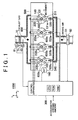
- FIG. 1 is an explanatory diagram showing an entire configuration of a gasoline engine 1000 according an embodiment of the invention.
- FIG 1 shows a cylinder block 500 of the gasoline engine 1000, in which four cylinders 200, 200a, 200b, 200c are provided.
- the cylinder 200 includes two intake valves 131, 131a.
- each of the cylinders 200a, 200b, 200c includes two intake valves.
- the gasoline 1000 includes a variable valve system in which a working angle and a lift amount of each intake valve of each cylinder are varied in association with each other.
- An intake manifold 540 supplies air to the cylinders 200, 200a, 200b, 200c.
- the intake manifold 540 communicates with an intake port 511 of the cylinder 200, and intake ports of the other cylinders 200a, 200b, 200c.
- the air passing through the intake manifold 540 is taken to each of the cylinders through each of the intake ports.
- a surge tank 50 is provided upstream of the intake manifold 540.
- the surge tank 50 is a calm tank which prevents pulsation of intake air.
- An intake air pressure sensor 51 which measures pressure of intake air flowing into the four cylinders through the intake manifold 540 is provided in the surge tank 50.
- Each of injectors 520, 520a, 520b, 520c injects fuel to the intake air passing through each of the intake ports of the four cylinders.
- An air-fuel mixture passes through the intake port 511 of the cylinder 200, flows into a combustion chamber 140, and then is burned by spark.
- the air-fuel mixture flowing into each of the cylinders 200a, 200b, 200c is burned by spark of spark plug 600a, 600b, 600c.
- the exhaust gas generated due to combustion is discharged to the outside of the cylinder block 500 by an exhaust manifold 700.
- FIG. 2 is an explanatory diagram showing a drive mechanism 100 which drives the intake valve 131.
- the drive mechanism 100 opens/closes the intake valve 131 using a stem end 130 as shown in a lower part of FIG. 2.
- the drive mechanism 100 is shown in detail.
- the intake cam shaft 110 and the intake cam 111 are rotated in association with the crank shaft of the gasoline engine 1000.
- An oscillating cam 150 has an input portion 103 and an output portion 104.
- the oscillating cam 150 oscillates according to rotation of the intake cam 111. Oscillation of the oscillating cam 150 allows driving force to be transmitted to the intake valve 131 through a locker arm 120 and the stem end 130. This opens the intake valve 131.
- a support pipe 101 is a hollow pipe.
- a control shaft 102 which can move in a z-axis direction (in an axis direction of the support pipe 101) extends in the support pipe 101. As shown in FIG 1, the control shaft 102 is moved in the z-axis direction by an actuator 160.
- a slider gear 150a is provided in an outer periphery of the support pipe 101.
- the slider gear 150a can move in the z-axis direction and can rotate around the z-axis, with respect to the support pipe 101.
- the slider gear 150a oscillates around the z-axis together with the oscillating cam 150.
- the slider gear 150a moves so as to follow movement of the control shaft 102 in the z-axis direction.
- the slider gear 150a and the input portion 103 are connected to each other with helical spline grooves thereof being fitted to each other.
- the slider gear 150a and the output portion 104 are connected to each other with helical spline grooves thereof being fitted to each other.
- the input portion 103 and the output portion 104 are different from the slider gear 150a in that they cannot move in the z-axis direction. Therefore, when the slider gear 150a moves in the z-axis direction, the input portion 103 and the output portion 104 oscillate around the z-axis.
- the thread direction of the spline grooves of the input portion 103 is opposite to the thread direction of the spline grooves of the output portion 104. Therefore, the input portion 103 and the output portion 104 oscillate in the opposite directions.
- the drive mechanism 100 is configured as described above, the valve opening characteristics of the intake valve 131 are varied when the shaft 102 is moved by the actuator 160.
- Each of the cylinders 200a, 200b, 200c has the same drive mechanism as the drive mechanism 100 of the cylinder 200.
- the control shaft 102 and the support pipe 101 which are moved by the actuator 160 extends through the drive mechanism 100 and the other three drive mechanisms.
- the four slider gears in each cylinder are fitted to the support pipe 101.
- the actuator 160 changes the valve opening characteristics of the cylinder 200 and the other cylinders by moving, in the z-axis direction, the control shaft 102 which extends through the drive mechanism 100 and the other three drive mechanisms.
- variable valve system shown in FIG. 1 and FIG. 2 is exemplary.
- a variable valve system including an oscillating cam, a variable valve system including a three-dimensional cam, or other variable valve systems of various types may be employed.
- a purification device 70, a temperature sensor 71, and oxygen sensors 81, 82 will be described in a modified example of the embodiment.
- the control apparatus 300 shown in FIG. 1 is a computer which includes a CPU, ROM, RAM, and the like.
- the control apparatus 300 controls operation of the gasoline engine 1000 by controlling various portions of the gasoline engine 1000.
- the control apparatus 300 controls a fuel injection amount of each of the injector 520 and the other injectors, ignition timing of each of the spark plug 600 and the other spark plugs, and movement of the control shaft 102 by the actuator 160.
- the control apparatus 300 obtains information from various sensors provided in the gasoline engine 1000.
- the control apparatus 300 obtains information on the accelerator opening amount, and information on the intake air pressure detected by the intake air pressure sensor 51.
- FIG. 3 is an explanatory diagram showing function blocks realized by the control apparatus 300.
- An operation control portion 310 decides a target working angle based on the accelerator opening amount.
- the operation control portion 310 refers to a map showing a relation between accelerator opening amounts and the target working angles, which is stored in an ACT setting portion 311.
- a working angle determination portion 312d detects the actual intake air amount in each of the four cylinders.
- the working angle determination portion 312d determines the actual intake air amount using the sensors and the like provided in the gasoline engine 1000, e.g., such as the intake air sensor 51. Also, the working angle determination portion 312d holds the map showing the relation between the intake air amount and the working angle in advance.
- the working angle determination 312d can determine the actual working angle of each cylinder according to the detected actual intake air amount by referring to the map.
- the working angle determination portion 312d may determine the actual intake air amount based on the throttle opening amount, the position of the control shaft 102, the intake air pressure and the air-fuel ratio of each cylinder, and the like. Also, the working angle determination portion 312 may determine the actual intake air amount according to the torque fluctuation or the fluctuation of the rotation of the gasoline engine 1000. The working angle determination portion 312d may use a so-called air flow meter which measures the intake air amount, or a so-called air-fuel ratio sensor. The working angle determination portion 312d may consider the temperature of the intake air or the coolant, or the result of measurement of thermal strain of the control shaft 102, in order to accurately estimate the actual intake air amount.
- the operation control portion 310 decides a target fuel injection amount for each cylinder, and target ignition timing for each cylinder.
- the operation control portion 310 instructs the target injection amount to each injector using an injection control portion 315, and instructs target ignition timing to each spark plug using an ignition control portion 316.
- the operation control portion 310 decides the target injection amount and the target ignition timing by referring to a basic storing portion 313a, an avoidance storing portion 314, and an integral storing portion 313b.
- the basic storing portion 313a and the integral storing portion 313b store torque information concerning the generated torque in each cylinder, and the avoidance storing portion 314 stores, as avoidance information, an air-fuel ratio region which needs to be avoided in order to maintain the purification level of exhaust gas.
- FIG. 4 is an explanatory diagram showing maps of the basic storing portion 313a and the avoidance storing portion 314.
- the basic storing portion 313a stores the relation between the air-fuel ratio and the generated torque for each of the actual working angles of the cylinders.
- FIG. 4 shows an example of the relation between the air-fuel ratio and the generated torque for each of the actual working angles of the four cylinders 200, 200a, 200b, 200c.
- the map stores the torque in the case where the basic ignition timing is employed. In the case where the basic ignition timing is employed, the ignition timing at which the generated torque becomes highest is employed as the basic ignition timing.
- the basic storing portion 313a may store the generated torque according to the fuel injection amount instead of the air-fuel ratio.
- the avoidance storing portion 314 may store the avoidance region according to the fuel injection amount, instead of the air-fuel ratio.
- the working angle is smallest in the cylinder 200, and the working angle increases in order of the cylinder 200, 200a, 200b, 200c.
- the actual intake air amount is smaller in a cylinder in which the actual working angle is smaller. Accordingly, the generated torque is lower in a cylinder in which the actual working angle is smaller, i.e., actual intake amount is smaller at the same air-fuel ratio (refer to square marks in FIG 4).
- the working angles are equal, as the air-fuel ratio is leaner, the generated torque in each cylinder is lower, and as the air-fuel ratio is richer, the generated torque in each cylinder is higher. In the region which is richer than the stoichiometric air-fuel ratio, however, the generated torque is not changed much even when the air-fuel ratio is changed.
- the avoidance storing portion 314 stores the air-fuel ratio region in which the emission amount is out of the permissible range (hereinafter, referred to as "avoidance region") as shown in a lower part of FIG 4.
- FIG. 5 is an explanatory diagram showing a map of the integral storing portion 313b.
- the integral storing portion 313b stores the map showing the relation between the ignition timing and the generated torque.
- the map is prepared for each combination of the fuel injection amount and the working angle. As shown in FIG. 5, the generated torque becomes lower as the ignition timing deviates from the basic ignition timing toward an advance angle side or a delay angle side to a larger extent.
- the invention is not limited to this mode of storing the torque information.
- the torque information may be stored using one multifactorial map showing the generated torque corresponding to the actual working angle, the fuel injection amount (or the air-fuel ratio), and the ignition timing in each cylinder.
- the control apparatus 300 may store an equation by which the generated torque can be derived.
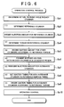
- FIG. 6 is a flowchart showing operation control process.
- the control apparatus 300 performs the operation control process shown in FIG. 6, thereby deciding the target injection amount and the target ignition timing for each cylinder, and operating the gasoline engine 1000 based on the decided target injection amount and the decided target ignition timing.
- step Sa1 the control apparatus 300 determines the actual intake air amount and the actual working angle in each of the cylinder 200 and the other three cylinders 200a, 200b, 200c, using the intake air pressure sensor 51 and the like.
- step Sa2 the control apparatus 300 determines a cylinder in which the actual working angle is smallest as the reference cylinder.
- the cylinder 200 is determined as the reference cylinder as shown in (1).
- step Sa3 the control apparatus 300 sets the target injection amount in the reference cylinder 200 to the basic injection amount for realizing the stoichiometric air-fuel ratio.
- step Sa4 the control apparatus 300 determines the reference torque generated in the reference cylinder 200 by referring to the basic storing portion 313a according to the air-fuel ratio and the working angle in the reference cylinder 200 (refer to (2) in FIG. 4).
- step Sa5 the control apparatus 300 decides the target injection amount for each of the other cylinders 200a, 200b, 200c such that the torque equal to the reference torque is generated (refer to (3) in FIG. 4).
- step Sa6 the control apparatus 300 examines whether the air-fuel ratio in each cylinder is in the avoidance region. In the example shown in (4) in FIG. 4, the air-fuel ratio in the cylinder 200a is out of the avoidance region, but the air-fuel ratio in each of the cylinders 200b, 200c is in the avoidance region.
- step Sa7 the control apparatus 300 modifies and redecides the target injection amount for the cylinders 200b, 200c in each of which the air-fuel ratio is in the avoidance region (hereinafter, referred to as "avoidance cylinders"). More specifically, the target injection amount is modified so as to achieve the air-fuel ratio which is out of the avoidance region, and at which the torque closest to the reference torque is generated (refer to (5) in FIG. 4).
- step Sa8 the control apparatus 300 sets the target ignition timing in the cylinders 200, 200a, in each of which the air-fuel ratio is out of the avoidance region (hereinafter, referred to as "non-avoidance cylinder") to the basic ignition timing (refer to (6) in FIG. 5).
- the basic ignition timing is employed, as shown in FIG 5, the generated torque in each of the non-avoidance cylinders 200, 200a becomes equal to the reference torque.
- step Sa9 in FIG. 6 the control apparatus 300 sets the ignition timing in each of the avoidance cylinders 200b, 200c such that the torque substantially equal to the reference torque is generated (refer to (7) in FIG 5).
- step Sa10 the control apparatus 300 performs operation control based on the target injection amount and the target ignition timing which is set for each cylinder.
- the air-fuel ratio and the ignition timing are integrally decided considering the torque generated in each cylinder, and the emission amount, instead of controlling operation of each cylinder such that the air-fuel ratio in each cylinder becomes equal.
- the purification level of exhaust gas can be maintained, and the torque fluctuation can be suppressed.
- the gasoline engine is employed.
- the technology in the embodiment can be applied to a diesel engine.
- the fuel injection timing may be controlled, instead of the ignition timing.
- the aforementioned technology may be used for operation for performing so-called lean burn at the air-fuel ratio leaner than the stoichiometric air-fuel ratio.
- the control apparatus 300 may modify the avoidance region (refer to FIG. 4) according to a deterioration degree of a catalyst in the internal combustion engine.
- the fuel injection amount is decided such that equal torque is generated in all of the four cylinders.
- the invention is not limited to this mode of deciding the fuel injection amount.
- description will be made of a case where the fuel injection amount and the like are decided such that the generated torque in each cylinder is in a predetermined permissible range.
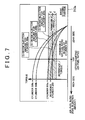
- FIG 7 is an explanatory diagram conceptually showing a process when small fluctuation is permitted.
- the map in FIG. 7 corresponds to the map in the basic storing portion 313a shown in FIG 4.
- FIG. 7 shows the permissible range of the generated torque.
- the permissible range shown in FIG. 7 is determined by a predetermined permissible width d of the generated torque.
- the permissible width d is set in the basic storing portion 313a in advance.
- the permissible width d is set such that torque fluctuation causes a problem if a difference between the generated torque in each of all the cylinders other than the reference cylinder and the reference torque in the reference cylinder is out of the permissible width d.
- step Sa5 in FIG. 6 the control apparatus 300 decides the target injection amount in the cylinders 200a, 200b, 200c other than the reference cylinder 200 such that the generated torque in each of the cylinders 200a, 200b, 200c is in the permissible range. More particularly, the control apparatus 300 decides the target injection amount so as to achieve the air-fuel ratio in the air-fuel ratio region shown by a dashed line (permissible region) in FIG. 7.
- the combustion condition which allows the purification level of exhaust gas to be highest can be employed in the range in which torque fluctuation does not occur.
- the cylinder in which the actual intake air amount is second smallest may be determined as the reference cylinder. Also, as the reference torque, it is possible to employ an intermediate value (for example, an average value) between the generated torque in the cylinder in which the actual intake air amount is smallest and the generated torque in the cylinder in which the actual intake air amount is second smallest.
- an intermediate value for example, an average value
- the ignition timing is adjusted only when the differences in the torque cannot be sufficiently suppressed only by adjusting the target injection amount. More particularly, priority is given to adjustment of the target injection amount. However, priority may be given to adjustment of the target ignition timing over adjustment of the target injection amount.
- FIG. 8 is an explanatory diagram showing the process when priority is given to adjustment of target ignition timing.
- the explanatory diagram in FIG. 8 corresponds to the explanatory diagram in FIG. 4 in the embodiment.
- the basic storing portion 313a maintains the map for storing the generated torque at each ignition timing when the basic injection amount is employed.
- the avoidance storing portion 314 stores, as the avoidance region, the ignition timing region in which a problem concerning the temperature of exhaust gas occurs.
- the operation control process in FIG. 8 is the same as the operation control process in the embodiment shown in FIG. 6 in principle.
- steps Sa1 to Sa4 in FIG. 6 as in the embodiment, the reference torque is set to the generated torque in the reference cylinder 200 in which the actual intake air amount is smallest when the basic ignition timing and basic injection amount are employed.
- the target ignition timing for each of the cylinders other than the reference cylinder is decided according to the reference torque in step Sa5.
- the modified example is different from the embodiment in which the target injection amount for each of the cylinders other than the reference cylinder is decided (refer to (3) in FIG. 8).
- step Sa6 it is examined whether each ignition timing decided in step Sa5 is in the avoidance region (refer to (4) in FIG. 8).
- step Sa7 the target ignition timing for each of the avoidance cylinders 200b, 200c is modified and decided (refer to (5) in FIG. 8). Subsequently, the control apparatus 300 sets the target injection amount for each of the non-avoidance cylinders 200, 200a to the basic injection amount (step Sa8). Also, the target injection amount for each of the avoidance cylinders 200b, 200c is decided such that the torque substantially equal to the reference torque is generated in each cylinder, as in the embodiment in FIG. 5 (step Sa9).
- the invention is not limited to a case where one of the target injection amount and the target ignition timing is adjusted with higher priority when deciding the target injection amount and the like.
- Both of the target injection amount and the target ignition timing may be integrally adjusted.
- an amount by which the fuel injection amount is deviated from the basic injection amount may be expressed by aX
- an amount by which the ignition timing is deviated from the basic ignition timing may be expressed by bX (each of a, b is a predetermined constant; and X is a variable).
- the target injection amount and the target ignition timing can be adjusted by changing the variable X.
- the operation control portion 310 may adjust only one of the target injection amount and the target ignition timing, and the other may be constantly fixed to the basic injection amount or the basic ignition timing.
- the ignition timing may be constantly fixed to the basic ignition timing by performing the process in the embodiment without setting the avoidance region.
- control apparatus 300 may select and perform one of the plural modes.
- the purification device 70 having the catalyst is provided in the gasoline 1000.
- the purification device 70 purifies the exhaust gas, and reduces the emission amount.
- the purification device 70 according to the embodiment achieves a high purification rate in a relatively large air-fuel ratio region, while storing and emitting oxygen in the exhaust gas.
- the performance of the purification device 70 varies according to the temperature of the catalyst and the amount of oxygen stored in the catalyst.
- the temperature sensor 71 that detects the temperature of the catalyst is provided in the purification device 76. Also, each of the two oxygen sensors 81, 82 (shown in FIG. 1), which are provided upstream and downstream of the purification device 70, detects the amount of oxygen contained in the exhaust gas flowing into or flowing out of the purification device 70. The results of measurement by the two oxygen sensors 81, 82 become different from each other according to the storage state of oxygen in the catalyst.
- the control apparatus 300 can estimate the performance of the purification device 70 according to the temperature of the catalyst, and the difference in the response between the two oxygen sensors 81, 82. Since the performance of the catalyst may vary according to the storage and adsorption state of material other than oxygen in the catalyst, the control apparatus 300 may detect or estimate the storage and adsorption state of material other than oxygen in the catalyst. Also, the control apparatus 300 may be able to detect a time-dependent decrease in the performance of the purification device 70.
- FIG. 9 is a flowchart showing the operation control process for switching modes of deciding the target injection amount and the target ignition timing.
- the control apparatus 300 determines whether the catalyst has deteriorated.
- the control apparatus 300 selectively performs one of step Sb31 and step Sb32 in the operation control process, according to whether the catalyst has deteriorated (step Sb2).
- step Sb31 When the catalyst has not deteriorated, the control apparatus 300 performs the operation control process in the mode in which only the target injection amount is adjusted (step Sb31). In this case, the ignition timing is fixed to the basic ignition timing. Meanwhile, when the catalyst has deteriorated, the control apparatus 300 performs the operation control process for adjusting not only the fuel injection amount but also the ignition timing in step Sb32. In step Sb32, the fuel injection amount close to the basic injection amount is employed as compared with the case where step Sb31 is performed while the intake air amount in each cylinder is the same as in step Sb32.
- control apparatus 300 selects the operation control process on the basis of the intake air amount, the generated torque, the working angle, inequality of these factors, the emission amount, the temperature of exhaust gas, the load of the internal combustion engine, or the like. Also, the control apparatus 300 may select the operation control process on the basis of various types of information concerning difficulty in avoiding torque fluctuation, difficulty in maintaining the purification level of exhaust gas, or the like.
- the control apparatus 300 may adjust only the fuel injection amount when a problem concerning an increase in the emission amount is not likely to occur, for example, when the catalyst has not deteriorated. Similarly, the control apparatus 300 may adjust only the ignition timing when a problem concerning an increase in the temperature of exhaust gas is not likely to occur.
- the control apparatus 300 may adjust one of the fuel injection amount and the ignition timing when torque fluctuation is not likely to occur, for example, when the difference in the working angle, the intake air amount, or the like is small, or when the working angle is large, and may adjust both of the fuel injection amount and the ignition timing when torque fluctuation is likely to occur.
- the control apparatus 300 may decide the fuel injection amount or the ignition timing considering only the purification level of exhaust gas, and without considering torque fluctuation. For example, when torque fluctuation is not likely to occur, the fuel injection amount may be controlled such that the air-fuel ratios in all of the cylinders become equal, in order to maintain the purification level of exhaust gas.
- the control apparatus 300 may adjust only the ignition timing when the internal combustion engine is idling, and may adjust both of the fuel injection amount and the ignition timing when the load of the internal combustion engine is low.
- a combustion condition for each of plural cylinders included in an internal combustion engine is set by the following control that is performed according to an intake air amount in each of the plural cylinders.
- a reference cylinder is set to a cylinder in which the intake air amount is smallest, and a fuel injection amount for the reference cylinder is set to a fuel injection amount for realizing a stoichiometric air-fuel ratio.
- the air-fuel ratio in each of the cylinders other than the reference cylinder is set according to the intake air amount in each of the cylinders such that the torque equal to reference torque generated in the reference cylinder is generated.
Landscapes
- Engineering & Computer Science (AREA)
- Chemical & Material Sciences (AREA)
- Combustion & Propulsion (AREA)
- Mechanical Engineering (AREA)
- General Engineering & Computer Science (AREA)
- Electrical Control Of Air Or Fuel Supplied To Internal-Combustion Engine (AREA)
- Combined Controls Of Internal Combustion Engines (AREA)
- Electrical Control Of Ignition Timing (AREA)
- Output Control And Ontrol Of Special Type Engine (AREA)
Abstract
Description
- The invention relates to an internal combustion engine including plural cylinders, a control apparatus and a control method for an internal combustion engine including plural cylinders.
- A gasoline engine is proposed, which includes a variable valve system in which valve opening characteristics such as opening/closing timing and an opening/closing amount of a valve are varied. In the gasoline engine including the variable valve system, an intake air amount of each cylinder can be controlled by changing valve opening characteristics of an intake valve (refer to Japanese Patent Laid-Open Publication No. JP-A-2001-263015).
- In the gasoline engine including the variable valve system, there may be irregular differences in valve opening characteristics of an intake valve among cylinders. Such differences in valve opening characteristics among cylinders cause a problem concerning the operating state of the internal combustion engine. For example, when a working angle or a lift amount is small, the differences in valve opening characteristics cause differences in the intake air amount among the cylinders. The differences in the intake air amount cause differences in the air-fuel ratio, which results in a problem such as an increase in an emission amount.
- Thus, in order to obtain a desired combustion state even when there are differences in the intake air amount among the cylinders, a technology is proposed, in which a fuel injection amount for each cylinder is decided according to the intake air amount in each cylinder. As an example of such a technology, Japanese Patent Laid-Open Publication No. JP-A-11-62639 discloses a technology in which a fuel injection amount for achieving a stoichiometric air-fuel ratio (hereinafter, referred to as "basic injection amount") is decided for each cylinder.
- However, when the fuel injection amounts in all of the cylinders are controlled such that the air-fuel ratios in all of the cylinders become equal, the torque generated in each cylinder (hereinafter, referred to as "generated torque") is different due to the fact that the intake air amount varies with each cylinder. The differences in the generated torque cause engine speed fluctuation or torque fluctuation.
- It is an object of the invention to provide a technology which can suppress both a variance in the air-fuel ratios of plural cylinders, and a fluctuation in torque.
- A first aspect of the invention relates to a control apparatus which controls operation of an internal combustion engine including plural cylinders. The control apparatus includes an obtaining portion that obtains a parameter concerning a valve opening characteristic of an intake valve of each of the plural cylinders; a combustion condition deciding portion that decides a combustion condition for each of the plural cylinders determined by at least one of a fuel injection amount and ignition timing, according to the parameter; and a control portion that controls operation of each of the plural cylinders under the decided combustion condition. Also, torque generated in each of the plural cylinders is decided according to the parameter and the combustion condition, and the combustion condition deciding portion decides the combustion condition such that a difference between the torque generated in each of the plural cylinders and reference torque is in a predetermined permissible range.
- With this arrangement, when deciding the combustion condition for each of the cylinders, torque fluctuation can be suppressed. Further, in the aforementioned control, the combustion condition may be set such that air-fuel ratios in the plural cylinders are in a predetermined region. Thus, it is possible to suppress both a variance in the air-fuel ratios of the plural cylinders, and a fluctuation in torque.
- It is preferable that the combustion condition deciding portion should estimate generated torque in each of the cylinders according to the parameter and the combustion condition. The generated torque can be estimated, for example, using a map or a function showing a relation between the parameter and the combustion condition, and the generated torque. Thus, the difference between the generated torque in each of the plural cylinders and the reference torque can be determined. The combustion condition deciding portion may decide the combustion condition such that the generated torque in each cylinder becomes equal. Alternatively, the combustion condition deciding portion may decide the combustion condition so as to permit the difference between the generated torque in each of the plural cylinders and the reference torque in a certain range. Flexibility in deciding the applicable combustion condition is increased by permitting the difference between the highest torque and the lowest torque in the certain range. Therefore, it is possible to reduce an adverse effect of the differences in the valve opening characteristics among the cylinders. Also, the internal combustion engine may be a diesel engine. In such a case, the control apparatus may perform control of the fuel injection timing instead of ignition timing.
- A second aspect of the invention relates to an internal combustion engine including plural cylinders, the aforementioned control apparatus, and a variable valve system in which the aforementioned valve opening characteristics are varied.
- As the variable valve system, a variable valve system including an oscillating cam, a variable valve system including a three-dimensional cam, or other variable valve systems of various types may be employed.
- In the case of an internal combustion engine including the variable valve system as in the second aspect of the invention, the obtaining portion may detect at least one of a working angle of the intake valve and a lift amount of the intake valve, intake air pressure in each of the cylinders, an intake air amount in each of the cylinders, and an air-fuel ratio in each of the cylinders, torque fluctuation in the internal combustion engine, and a temperature at a predetermined portion of the internal combustion engine, in order to obtain the aforementioned parameter.
- With this arrangement, the control apparatus can estimate the valve opening characteristic of each intake valve. Thus, since the combustion condition can be selected according to an actual valve opening characteristic, a desired air-fuel ratio and a desired generated torque can be achieved with high accuracy. The control apparatus may estimate the differences in the valve opening characteristic among the cylinders by measuring thermal strain generated in the variable valve system.
- In the internal combustion engine including the variable valve system, the combustion condition deciding portion may decide the combustion condition in various modes. For example, the parameter may show the intake air amount in each of the cylinders, and the combustion condition deciding portion may set the fuel injection amount such that the air-fuel ratio becomes higher in a cylinder in which the intake air amount is larger.
- When the air-fuel ratio in each cylinder is equal, the generated torque increases with an increase in the intake air amount. Considering this phenomenon, in the aforementioned control apparatus, the air-fuel ratio is made higher, that is, the air-fuel ratio is made leaner in a cylinder in which the intake air amount is larger, whereby a difference between the highest generated torque and the lowest generated torque in the cylinders can be reduced.
- The control apparatus may set a target air-fuel ratio in each of the cylinders to an air-fuel ratio in a region which is higher than the stoichiometric air-fuel ratio, that is, a region which is leaner than the stoichiometric air-fuel ratio. In the region which is leaner than the stoichiometric air-fuel ratio, a change in the generated torque is large with respect to a change in the air-fuel ratio. Therefore, the generated torque can be changed in a large range by adjusting the air-fuel ratio in the region which is leaner than the stoichiometric air-fuel ratio.
- In the internal combustion engine including the variable valve system, the parameter may show the intake air amount in each of the cylinders, and the combustion condition deciding portion may include a reference cylinder setting portion that sets, as a reference cylinder, one of at least one cylinder among the plural cylinders other than a cylinder in which the intake air amount is largest (that is, the reference cylinder setting portion that sets, as a reference cylinder, a cylinder in which the intake air amount is not largest), may set, as the reference torque, torque generated in the reference cylinder, and may decide the combustion condition for at least one cylinder other than the reference cylinder according to the parameter concerning the reference cylinder.
- In general, the generated torque does not increase unlimitedly even when increasing the fuel injection amount. Therefore, there are cases where the torque that is equal to the generated torque in a cylinder in which the intake air amount is largest cannot be generated in a cylinder in which the intake air amount is small, even when increasing the fuel injection amount in the cylinder in which the intake air amount is small. Since the reference cylinder is set to a cylinder in which the intake air amount is not largest, the torque that is equal to the torque in the reference cylinder (reference torque) can be generated in each of the cylinders other than the reference cylinder. Therefore, the torque in each cylinder can be made equal. In view of this, it is preferable that the reference cylinder should be a cylinder in which the intake air amount is smallest. The combustion condition deciding portion may directly decide the combustion condition for the at least one cylinder other than the reference cylinder, using the parameter concerning the reference cylinder. Also, the combustion condition deciding portion may decide the combustion condition for the cylinders other than the reference cylinder such that the torque in each of the cylinders other than the reference cylinder becomes equal to the reference torque by estimating the generated torque in the reference cylinder based on the parameter concerning the reference cylinder.
- In the aforementioned control apparatus, the parameter may show the intake air amount in each of the cylinders, and the combustion condition deciding portion may decide the fuel injection amount according to the parameter such that air-fuel ratios of the plural cylinders are in a predetermined permissible region.
- A change in the fuel injection amount causes a large change in the generated torque, which results in torque fluctuation. In the aforementioned control apparatus, however, even when changing the fuel injection amount according to the condition for the air-fuel ratio, the condition for the air-fuel ratio can be satisfied, and the torque fluctuation can be suppressed. The permissible range of the air-fuel ratio may be set to a range in which an adverse effect of an increase in the emission amount can be avoided.
- The combustion condition deciding portion may fix the fuel injection amount to a basic injection amount. In such a case, torque fluctuation can be avoided by adjusting the ignition timing. Since the fuel injection amount is fixed to the basic injection amount, the emission amount can be reduced. The combustion condition deciding portion may fix the ignition timing to predetermined basic ignition timing and may adjust the fuel injection amount so that torque fluctuation is avoided. When the ignition timing is fixed to predetermined basic ignition timing, the predetermined basic ignition timing may be ignition timing at which the torque becomes highest. Since the ignition timing is fixed to the basic ignition timing, it is possible to prevent an increase in a temperature of exhaust gas. Further, the combustion condition deciding portion may adjust both the fuel injection amount and the ignition timing in order to avoid torque fluctuation. With this arrangement, it is possible to suppress an excessive increase in the emission amount and an excessive increase in the temperature of exhaust gas. Also, the generated torque can be changed to a large extent. The combustion condition deciding portion may decide one of the fuel injection amount and the ignition timing with higher priority, and may decide the other according to a result of the decision.
- Thus, as the method in which the aforementioned control apparatus decides the combustion condition, various methods may be employed. The aforementioned control apparatus may include an operating state obtaining portion that obtains predetermined information concerning an operating state of the internal combustion engine, and the combustion condition deciding portion may switch among plural modes of deciding the combustion condition that are prepared in advance, according to the obtained predetermined information.
- With this arrangement, switching can be performed among the different combustion conditions according to the operating state of the internal combustion engine.
- The control apparatus may fix the ignition timing to the basic ignition timing, and may adjust only the fuel injection amount when the emission amount is not likely to increase, for example, when a catalyst has not deteriorated.
- Also, when the working angle varies to a small extent with each cylinder, or when the working angle or the like is large, torque fluctuation is not likely to occur. The control apparatus may adjust one of the fuel injection amount and the ignition timing when torque fluctuation is not likely to occur, and may adjust both of the fuel injection amount and the ignition timing when torque fluctuation is likely to occur. Also, the arrangement may be such that the control apparatus does not consider the condition concerning the difference in torque when torque fluctuation is not likely to occur. For example, when torque fluctuation is not likely to occur, the fuel injection amount may be fixed to the basic injection amount in order to maintain a certain purification level of exhaust gas.
- The control apparatus may adjust only the ignition timing while the internal combustion engine is idling, and may adjust both of the fuel injection amount and the ignition timing while a load of the engine is low.
- The invention can be configured in various aspects such as an operation method or a control method for an internal combustion engine (including an operating method of an internal combustion engine), in addition to aspects as a control apparatus for an internal combustion engine and an internal combustion engine.
- The foregoing and further objects, features and advantages of the invention will become apparent from the following description of preferred embodiments with reference to the accompanying drawings, wherein like numerals are used to represent like elements and wherein:
- FIG. 1 is an explanatory diagram showing an entire configuration of a
gasoline engine 1000 according to an embodiment of the invention; - FIG. 2 is an explanatory diagram showing a
drive mechanism 100 which drives anintake valve 131; - FIG. 3 is an explanatory diagram showing function blocks realized by a
control apparatus 300; - FIG. 4 is an explanatory diagram showing maps of a
basic storing portion 313a and anavoidance storing portion 314; - FIG. 5 is an explanatory diagram showing a map of an
integral storing portion 313b; - FIG. 6 is a flowchart showing an operating control process;
- FIG. 7 is an explanatory diagram conceptually showing a process when small fluctuation is permitted;
- FIG. 8 is an explanatory diagram showing a process when priority is given to adjustment of target ignition timing; and
- FIG. 9 is a flowchart showing an operating control process for switching among modes of deciding a target injection amount and target ignition timing.
- Hereinafter, embodiments of the invention will be described in the following order.
- A. Entire configuration
- B. Configuration of functional blocks
- C. Process
- D. Modified example 1; a permissible range
- E. Modified example 2; a decision mode
- F. Modified example 3; switching among modes
- FIG. 1 is an explanatory diagram showing an entire configuration of a
gasoline engine 1000 according an embodiment of the invention. FIG 1 shows acylinder block 500 of thegasoline engine 1000, in which fourcylinders cylinder 200 includes twointake valves cylinders gasoline 1000 includes a variable valve system in which a working angle and a lift amount of each intake valve of each cylinder are varied in association with each other. - An
intake manifold 540 supplies air to thecylinders intake manifold 540 communicates with anintake port 511 of thecylinder 200, and intake ports of theother cylinders intake manifold 540 is taken to each of the cylinders through each of the intake ports. Asurge tank 50 is provided upstream of theintake manifold 540. Thesurge tank 50 is a calm tank which prevents pulsation of intake air. An intakeair pressure sensor 51 which measures pressure of intake air flowing into the four cylinders through theintake manifold 540 is provided in thesurge tank 50. - Each of
injectors intake port 511 of thecylinder 200, flows into acombustion chamber 140, and then is burned by spark. Similarly, the air-fuel mixture flowing into each of thecylinders spark plug cylinder block 500 by an exhaust manifold 700. - FIG. 2 is an explanatory diagram showing a
drive mechanism 100 which drives theintake valve 131. Thedrive mechanism 100 opens/closes theintake valve 131 using astem end 130 as shown in a lower part of FIG. 2. - In an upper part of FIG. 2, the
drive mechanism 100 is shown in detail. Theintake cam shaft 110 and theintake cam 111 are rotated in association with the crank shaft of thegasoline engine 1000. An oscillating cam 150 has aninput portion 103 and anoutput portion 104. The oscillating cam 150 oscillates according to rotation of theintake cam 111. Oscillation of the oscillating cam 150 allows driving force to be transmitted to theintake valve 131 through alocker arm 120 and thestem end 130. This opens theintake valve 131. - A support pipe 101 is a hollow pipe. A
control shaft 102 which can move in a z-axis direction (in an axis direction of the support pipe 101) extends in the support pipe 101. As shown in FIG 1, thecontrol shaft 102 is moved in the z-axis direction by anactuator 160. - A
slider gear 150a is provided in an outer periphery of the support pipe 101. Theslider gear 150a can move in the z-axis direction and can rotate around the z-axis, with respect to the support pipe 101. Theslider gear 150a oscillates around the z-axis together with the oscillating cam 150. Theslider gear 150a moves so as to follow movement of thecontrol shaft 102 in the z-axis direction. - The
slider gear 150a and theinput portion 103 are connected to each other with helical spline grooves thereof being fitted to each other. Theslider gear 150a and theoutput portion 104 are connected to each other with helical spline grooves thereof being fitted to each other. Theinput portion 103 and theoutput portion 104 are different from theslider gear 150a in that they cannot move in the z-axis direction. Therefore, when theslider gear 150a moves in the z-axis direction, theinput portion 103 and theoutput portion 104 oscillate around the z-axis. The thread direction of the spline grooves of theinput portion 103 is opposite to the thread direction of the spline grooves of theoutput portion 104. Therefore, theinput portion 103 and theoutput portion 104 oscillate in the opposite directions. - The
drive mechanism 100 is configured as described above, the valve opening characteristics of theintake valve 131 are varied when theshaft 102 is moved by theactuator 160. - Each of the
cylinders drive mechanism 100 of thecylinder 200. Thecontrol shaft 102 and the support pipe 101 which are moved by theactuator 160 extends through thedrive mechanism 100 and the other three drive mechanisms. The four slider gears in each cylinder are fitted to the support pipe 101. The actuator 160 changes the valve opening characteristics of thecylinder 200 and the other cylinders by moving, in the z-axis direction, thecontrol shaft 102 which extends through thedrive mechanism 100 and the other three drive mechanisms. - The variable valve system shown in FIG. 1 and FIG. 2 is exemplary. As the variable valve system, a variable valve system including an oscillating cam, a variable valve system including a three-dimensional cam, or other variable valve systems of various types may be employed. For example, it is possible to employ a variable valve system in which the valve opening characteristics of each of the
cylinder 200 and the other three cylinders are separately varied. - A
purification device 70, atemperature sensor 71, andoxygen sensors - The
control apparatus 300 shown in FIG. 1 is a computer which includes a CPU, ROM, RAM, and the like. Thecontrol apparatus 300 controls operation of thegasoline engine 1000 by controlling various portions of thegasoline engine 1000. For example, thecontrol apparatus 300 controls a fuel injection amount of each of theinjector 520 and the other injectors, ignition timing of each of thespark plug 600 and the other spark plugs, and movement of thecontrol shaft 102 by theactuator 160. In order to perform these controls, thecontrol apparatus 300 obtains information from various sensors provided in thegasoline engine 1000. For example, thecontrol apparatus 300 obtains information on the accelerator opening amount, and information on the intake air pressure detected by the intakeair pressure sensor 51. - FIG. 3 is an explanatory diagram showing function blocks realized by the
control apparatus 300. Anoperation control portion 310 decides a target working angle based on the accelerator opening amount. When deciding the target working angle, theoperation control portion 310 refers to a map showing a relation between accelerator opening amounts and the target working angles, which is stored in anACT setting portion 311. - A working
angle determination portion 312d detects the actual intake air amount in each of the four cylinders. The workingangle determination portion 312d determines the actual intake air amount using the sensors and the like provided in thegasoline engine 1000, e.g., such as theintake air sensor 51. Also, the workingangle determination portion 312d holds the map showing the relation between the intake air amount and the working angle in advance. The workingangle determination 312d can determine the actual working angle of each cylinder according to the detected actual intake air amount by referring to the map. - The working
angle determination portion 312d may determine the actual intake air amount based on the throttle opening amount, the position of thecontrol shaft 102, the intake air pressure and the air-fuel ratio of each cylinder, and the like. Also, the working angle determination portion 312 may determine the actual intake air amount according to the torque fluctuation or the fluctuation of the rotation of thegasoline engine 1000. The workingangle determination portion 312d may use a so-called air flow meter which measures the intake air amount, or a so-called air-fuel ratio sensor. The workingangle determination portion 312d may consider the temperature of the intake air or the coolant, or the result of measurement of thermal strain of thecontrol shaft 102, in order to accurately estimate the actual intake air amount. - The
operation control portion 310 decides a target fuel injection amount for each cylinder, and target ignition timing for each cylinder. Theoperation control portion 310 instructs the target injection amount to each injector using aninjection control portion 315, and instructs target ignition timing to each spark plug using anignition control portion 316. - The
operation control portion 310 decides the target injection amount and the target ignition timing by referring to abasic storing portion 313a, anavoidance storing portion 314, and anintegral storing portion 313b. Thebasic storing portion 313a and theintegral storing portion 313b store torque information concerning the generated torque in each cylinder, and theavoidance storing portion 314 stores, as avoidance information, an air-fuel ratio region which needs to be avoided in order to maintain the purification level of exhaust gas. - FIG. 4 is an explanatory diagram showing maps of the
basic storing portion 313a and theavoidance storing portion 314. Thebasic storing portion 313a stores the relation between the air-fuel ratio and the generated torque for each of the actual working angles of the cylinders. FIG. 4 shows an example of the relation between the air-fuel ratio and the generated torque for each of the actual working angles of the fourcylinders basic storing portion 313a may store the generated torque according to the fuel injection amount instead of the air-fuel ratio. Theavoidance storing portion 314 may store the avoidance region according to the fuel injection amount, instead of the air-fuel ratio. - In FIG. 4, the working angle is smallest in the
cylinder 200, and the working angle increases in order of thecylinder - The
avoidance storing portion 314 stores the air-fuel ratio region in which the emission amount is out of the permissible range (hereinafter, referred to as "avoidance region") as shown in a lower part of FIG 4. - FIG. 5 is an explanatory diagram showing a map of the
integral storing portion 313b. Theintegral storing portion 313b stores the map showing the relation between the ignition timing and the generated torque. The map is prepared for each combination of the fuel injection amount and the working angle. As shown in FIG. 5, the generated torque becomes lower as the ignition timing deviates from the basic ignition timing toward an advance angle side or a delay angle side to a larger extent. - In the embodiment, two maps for storing torque information are prepared, and each of the two maps is stored in the
basic storing portion 313a and theintegral storing portion 313b. However, the invention is not limited to this mode of storing the torque information. The torque information may be stored using one multifactorial map showing the generated torque corresponding to the actual working angle, the fuel injection amount (or the air-fuel ratio), and the ignition timing in each cylinder. Thecontrol apparatus 300 may store an equation by which the generated torque can be derived. - FIG. 6 is a flowchart showing operation control process. The
control apparatus 300 performs the operation control process shown in FIG. 6, thereby deciding the target injection amount and the target ignition timing for each cylinder, and operating thegasoline engine 1000 based on the decided target injection amount and the decided target ignition timing. - In step Sa1, the
control apparatus 300 determines the actual intake air amount and the actual working angle in each of thecylinder 200 and the other threecylinders air pressure sensor 51 and the like. In step Sa2, thecontrol apparatus 300 determines a cylinder in which the actual working angle is smallest as the reference cylinder. In the example shown in FIG. 4, thecylinder 200 is determined as the reference cylinder as shown in (1). In step Sa3, thecontrol apparatus 300 sets the target injection amount in thereference cylinder 200 to the basic injection amount for realizing the stoichiometric air-fuel ratio. In step Sa4, thecontrol apparatus 300 determines the reference torque generated in thereference cylinder 200 by referring to thebasic storing portion 313a according to the air-fuel ratio and the working angle in the reference cylinder 200 (refer to (2) in FIG. 4). - In step Sa5, the
control apparatus 300 decides the target injection amount for each of theother cylinders control apparatus 300 examines whether the air-fuel ratio in each cylinder is in the avoidance region. In the example shown in (4) in FIG. 4, the air-fuel ratio in thecylinder 200a is out of the avoidance region, but the air-fuel ratio in each of thecylinders - In step Sa7, the
control apparatus 300 modifies and redecides the target injection amount for thecylinders - In step Sa8, the
control apparatus 300 sets the target ignition timing in thecylinders non-avoidance cylinders control apparatus 300 sets the ignition timing in each of theavoidance cylinders - In step Sa10, the
control apparatus 300 performs operation control based on the target injection amount and the target ignition timing which is set for each cylinder. - In the
gasoline engine 1000 thus described, the air-fuel ratio and the ignition timing are integrally decided considering the torque generated in each cylinder, and the emission amount, instead of controlling operation of each cylinder such that the air-fuel ratio in each cylinder becomes equal. As a result, even when the actual intake air amount varies with each cylinder, the purification level of exhaust gas can be maintained, and the torque fluctuation can be suppressed. - In the embodiment that has been described, the gasoline engine is employed. However, the technology in the embodiment can be applied to a diesel engine. When controlling operation of a diesel engine, the fuel injection timing may be controlled, instead of the ignition timing. Also, the aforementioned technology may be used for operation for performing so-called lean burn at the air-fuel ratio leaner than the stoichiometric air-fuel ratio. Further, the
control apparatus 300 may modify the avoidance region (refer to FIG. 4) according to a deterioration degree of a catalyst in the internal combustion engine. - In the embodiment, the fuel injection amount is decided such that equal torque is generated in all of the four cylinders. However, the invention is not limited to this mode of deciding the fuel injection amount. Hereinafter, description will be made of a case where the fuel injection amount and the like are decided such that the generated torque in each cylinder is in a predetermined permissible range.
- FIG 7 is an explanatory diagram conceptually showing a process when small fluctuation is permitted. The map in FIG. 7 corresponds to the map in the
basic storing portion 313a shown in FIG 4. FIG. 7 shows the permissible range of the generated torque. The permissible range shown in FIG. 7 is determined by a predetermined permissible width d of the generated torque. The permissible width d is set in thebasic storing portion 313a in advance. The permissible width d is set such that torque fluctuation causes a problem if a difference between the generated torque in each of all the cylinders other than the reference cylinder and the reference torque in the reference cylinder is out of the permissible width d. - In step Sa5 in FIG. 6, the
control apparatus 300 decides the target injection amount in thecylinders reference cylinder 200 such that the generated torque in each of thecylinders control apparatus 300 decides the target injection amount so as to achieve the air-fuel ratio in the air-fuel ratio region shown by a dashed line (permissible region) in FIG. 7. - Thus, the combustion condition which allows the purification level of exhaust gas to be highest can be employed in the range in which torque fluctuation does not occur.
- When a difference in the intake air amount between the cylinder in which the actual intake air amount is smallest, and the cylinder in which the actual intake air amount is second smallest is equal to or smaller than a predetermined value, the cylinder in which the actual intake air amount is second smallest may be determined as the reference cylinder. Also, as the reference torque, it is possible to employ an intermediate value (for example, an average value) between the generated torque in the cylinder in which the actual intake air amount is smallest and the generated torque in the cylinder in which the actual intake air amount is second smallest.
- In the embodiment, the ignition timing is adjusted only when the differences in the torque cannot be sufficiently suppressed only by adjusting the target injection amount. More particularly, priority is given to adjustment of the target injection amount. However, priority may be given to adjustment of the target ignition timing over adjustment of the target injection amount.
- FIG. 8 is an explanatory diagram showing the process when priority is given to adjustment of target ignition timing. The explanatory diagram in FIG. 8 corresponds to the explanatory diagram in FIG. 4 in the embodiment. In FIG. 8, the
basic storing portion 313a maintains the map for storing the generated torque at each ignition timing when the basic injection amount is employed. Theavoidance storing portion 314 stores, as the avoidance region, the ignition timing region in which a problem concerning the temperature of exhaust gas occurs. - The operation control process in FIG. 8 is the same as the operation control process in the embodiment shown in FIG. 6 in principle. In steps Sa1 to Sa4 in FIG. 6, as in the embodiment, the reference torque is set to the generated torque in the
reference cylinder 200 in which the actual intake air amount is smallest when the basic ignition timing and basic injection amount are employed. In the modified example, the target ignition timing for each of the cylinders other than the reference cylinder is decided according to the reference torque in step Sa5. Thus, the modified example is different from the embodiment in which the target injection amount for each of the cylinders other than the reference cylinder is decided (refer to (3) in FIG. 8). In step Sa6, it is examined whether each ignition timing decided in step Sa5 is in the avoidance region (refer to (4) in FIG. 8). In step Sa7, the target ignition timing for each of theavoidance cylinders control apparatus 300 sets the target injection amount for each of thenon-avoidance cylinders avoidance cylinders - The invention is not limited to a case where one of the target injection amount and the target ignition timing is adjusted with higher priority when deciding the target injection amount and the like. Both of the target injection amount and the target ignition timing may be integrally adjusted. For example, an amount by which the fuel injection amount is deviated from the basic injection amount may be expressed by aX, and an amount by which the ignition timing is deviated from the basic ignition timing may be expressed by bX (each of a, b is a predetermined constant; and X is a variable). In this case, the target injection amount and the target ignition timing can be adjusted by changing the variable X.
- The
operation control portion 310 may adjust only one of the target injection amount and the target ignition timing, and the other may be constantly fixed to the basic injection amount or the basic ignition timing. For example, the ignition timing may be constantly fixed to the basic ignition timing by performing the process in the embodiment without setting the avoidance region. - As described above, various modes of deciding the target injection amount and the target ignition timing may be employed. The
control apparatus 300 may select and perform one of the plural modes. - As shown in FIG. 1, the
purification device 70 having the catalyst is provided in thegasoline 1000. Thepurification device 70 purifies the exhaust gas, and reduces the emission amount. Thepurification device 70 according to the embodiment achieves a high purification rate in a relatively large air-fuel ratio region, while storing and emitting oxygen in the exhaust gas. The performance of thepurification device 70 varies according to the temperature of the catalyst and the amount of oxygen stored in the catalyst. - The
temperature sensor 71 that detects the temperature of the catalyst is provided in the purification device 76. Also, each of the twooxygen sensors 81, 82 (shown in FIG. 1), which are provided upstream and downstream of thepurification device 70, detects the amount of oxygen contained in the exhaust gas flowing into or flowing out of thepurification device 70. The results of measurement by the twooxygen sensors - The
control apparatus 300 can estimate the performance of thepurification device 70 according to the temperature of the catalyst, and the difference in the response between the twooxygen sensors control apparatus 300 may detect or estimate the storage and adsorption state of material other than oxygen in the catalyst. Also, thecontrol apparatus 300 may be able to detect a time-dependent decrease in the performance of thepurification device 70. - FIG. 9 is a flowchart showing the operation control process for switching modes of deciding the target injection amount and the target ignition timing. In step Sb1, the
control apparatus 300 determines whether the catalyst has deteriorated. Thecontrol apparatus 300 selectively performs one of step Sb31 and step Sb32 in the operation control process, according to whether the catalyst has deteriorated (step Sb2). - When the catalyst has not deteriorated, the
control apparatus 300 performs the operation control process in the mode in which only the target injection amount is adjusted (step Sb31). In this case, the ignition timing is fixed to the basic ignition timing. Meanwhile, when the catalyst has deteriorated, thecontrol apparatus 300 performs the operation control process for adjusting not only the fuel injection amount but also the ignition timing in step Sb32. In step Sb32, the fuel injection amount close to the basic injection amount is employed as compared with the case where step Sb31 is performed while the intake air amount in each cylinder is the same as in step Sb32. - By using the aforementioned process, switching can be performed among the different combustion conditions according to the performance of the catalyst.
- The basis on which the
control apparatus 300 selects the operation control process is not limited to a basis regarding the performance of the catalyst, and various bases may be employed. For example, thecontrol apparatus 300 may select the operation control process on the basis of the intake air amount, the generated torque, the working angle, inequality of these factors, the emission amount, the temperature of exhaust gas, the load of the internal combustion engine, or the like. Also, thecontrol apparatus 300 may select the operation control process on the basis of various types of information concerning difficulty in avoiding torque fluctuation, difficulty in maintaining the purification level of exhaust gas, or the like. - The
control apparatus 300 may adjust only the fuel injection amount when a problem concerning an increase in the emission amount is not likely to occur, for example, when the catalyst has not deteriorated. Similarly, thecontrol apparatus 300 may adjust only the ignition timing when a problem concerning an increase in the temperature of exhaust gas is not likely to occur. - The
control apparatus 300 may adjust one of the fuel injection amount and the ignition timing when torque fluctuation is not likely to occur, for example, when the difference in the working angle, the intake air amount, or the like is small, or when the working angle is large, and may adjust both of the fuel injection amount and the ignition timing when torque fluctuation is likely to occur. When torque fluctuation is not likely to occur, thecontrol apparatus 300 may decide the fuel injection amount or the ignition timing considering only the purification level of exhaust gas, and without considering torque fluctuation. For example, when torque fluctuation is not likely to occur, the fuel injection amount may be controlled such that the air-fuel ratios in all of the cylinders become equal, in order to maintain the purification level of exhaust gas. - The
control apparatus 300 may adjust only the ignition timing when the internal combustion engine is idling, and may adjust both of the fuel injection amount and the ignition timing when the load of the internal combustion engine is low. - The internal combustion engine and the control apparatus for an internal combustion engine according to the embodiments of the invention have been described. However, the embodiments of the invention that have been described are exemplary embodiments for promoting understanding of the invention, and the invention is not limited to the embodiments. Various changes and modifications can be made without departing from the true spirit of the invention.
- In the invention, the aforementioned various embodiment and the modified examples may be appropriately combined, or may be employed with part thereof being omitted.
- A combustion condition for each of plural cylinders included in an internal combustion engine is set by the following control that is performed according to an intake air amount in each of the plural cylinders. A reference cylinder is set to a cylinder in which the intake air amount is smallest, and a fuel injection amount for the reference cylinder is set to a fuel injection amount for realizing a stoichiometric air-fuel ratio. The air-fuel ratio in each of the cylinders other than the reference cylinder is set according to the intake air amount in each of the cylinders such that the torque equal to reference torque generated in the reference cylinder is generated. When this setting is performed, air-fuel ratios that are out of a predetermined region in the vicinity of the stoichiometric air-fuel ratio (i.e., air-fuel ratios that are in an avoidance region) are excluded. With respect to a cylinder in which the torque equal to the reference torque cannot be generated only by setting the air-fuel ratio, correction of the ignition timing is further performed so as to suppress a difference between the torque generated in the cylinder and the reference torque.
Claims (14)
- A control apparatus which controls operation of an internal combustion engine (1000) including plural cylinders, characterized by comprising:an obtaining portion (312d) that obtains a parameter concerning a valve opening characteristic of an intake valve of each of the plural cylinders;a combustion condition deciding portion (300) that decides a combustion condition for each of the plural cylinders determined by at least one of a fuel injection amount and ignition timing, according to the parameter; anda control portion (310) that controls operation of each of the plural cylinders under the decided combustion condition, wherein torque generated in each of the plural cylinders is decided according to the parameter and the combustion condition, and the combustion condition deciding portion (300) decides the combustion condition such that a difference between the torque generated in each of the plural cylinders and reference torque is in a predetermined permissible range.
- The control apparatus according to claim 1, wherein the parameter shows an intake air amount in each of the plural cylinders, and the combustion condition deciding portion (300) decides the fuel injection amount for each of the plural cylinders according to the parameter such that air-fuel ratios in the plural cylinders are in a predetermined permissible region.
- The control apparatus according to claim 1, wherein the control apparatus includes an operating state obtaining portion (312d) that obtains predetermined information concerning an operating state of the internal combustion engine (1000), and the combustion condition deciding portion (300) switches among plural modes of deciding the combustion condition that are prepared in advance, according to the obtained predetermined information.
- The control apparatus according to claim 3, wherein the internal combustion engine (1000) includes a catalyst that purifies exhaust gas; the operating state obtaining portion (312d) obtains, as the predetermined information, information on whether the catalyst has deteriorated; and the combustion condition deciding portion (300) adjusts both of the fuel injection amount and the ignition timing when the operating state obtaining portion (312d) obtains information that the catalyst has deteriorated, and the combustion condition deciding portion (300) adjusts only the fuel injection amount among the fuel injection amount and the ignition timing when the operating state obtaining portion (312d) obtains information that the catalyst has not deteriorated.
- An internal combustion engine (1000) which includes plural cylinders, characterized by comprising:the control apparatus according to claim 1; anda variable valve system (100) in which the valve opening characteristic is varied.
- The internal combustion engine (1000) according to claim 5, wherein the operating state obtaining portion (312d) detects at least one of a working angle of the intake valve, a lift amount of the intake valve, intake air pressure in each of the plural cylinders, an intake air amount in each of the plural cylinders, and an air-fuel ratio in each of the plural cylinders, torque fluctuation in the internal combustion engine (1000), and a temperature at a predetermined portion of the internal combustion engine (1000), in order to obtain the parameter.
- The internal combustion engine (1000) according to claim 6, wherein the parameter shows the intake air amount in each of the plural cylinders, and the combustion condition deciding portion (300) sets the fuel injection amount such that the air-fuel ratio is higher in a cylinder in which the intake air amount is larger.
- The internal combustion engine (1000) according to claim 6, wherein the parameter shows the intake air amount in each of the plural cylinders; the combustion condition deciding portion (300) includes a reference cylinder setting portion that sets, as a reference cylinder, one of at least one cylinder among the plural cylinders other than a cylinder in which the intake air amount is largest; the combustion condition deciding portion sets, as the reference torque, torque generated in the reference cylinder; and the combustion condition deciding portion decides the combustion condition for at least one cylinder other than the reference cylinder according to the parameter concerning the reference cylinder.
- The internal combustion engine (1000) according to claim 8, wherein, in a case where there is at least one first cylinder in which the air-fuel ratio is out of a predetermined permissible region among the at least one cylinder other than the reference cylinder when the combustion condition deciding portion (300) adjusts the combustion condition for the at least one cylinder other than the reference cylinder such that the difference between the torque generated in each of the plural cylinders and the reference torque is in a predetermined permissible range, the combustion condition deciding portion (300) adjusts the fuel injection amount in the at least one first cylinder such that the air-fuel ratio in the at least one first cylinder is placed in the predetermined permissible region again.
- The internal combustion engine (1000) according to claim 9, wherein, in a case where a difference between torque generated in at least one second cylinder among the at least one first cylinder and the reference torque is out of the predetermined permissible range after the combustion condition deciding portion (300) adjusts the fuel injection amount in the at least one first cylinder, the combustion condition deciding portion (300) adjust the ignition timing in the at least one second cylinder such that the difference between the torque in the at least one second cylinder and the reference torque is placed in the predetermined permissible range.
- The internal combustion engine according to any one of claims 5 to 10, wherein the combustion condition deciding portion (300) decides the combustion condition for each of the plural cylinders such that the torque generated in each of the plural cylinders becomes equal to the reference torque.
- The internal combustion engine according to any one of claims 5 to 10, wherein the combustion condition deciding portion (300) decides the combustion condition for each of the plural cylinders such that the difference between the torque generated in each of the plural cylinders and the reference torque is in a predetermined value.
- A control method of controlling operation of an internal combustion engine (1000) which includes plural cylinders, characterized by comprising the steps of:obtaining a parameter concerning a valve opening characteristic of an intake valve of each of the plural cylinders (Sa1);deciding a combustion condition for each of the plural cylinders determined by at least one of a fuel injection amount and ignition timing, according to the parameter (Sa3, Sa4, Sa5, Sa7, Sa8, Sa9); andcontrolling operation of each of the plural cylinders under the decided combustion condition, wherein torque generated in each of the plural cylinders is decided according to the parameter and the combustion condition, and the combustion condition for each of the plural cylinders is decided such that a difference between the torque generated in each of the plural cylinders and reference torque is in a predetermined permissible range (Sa5, Sa9, Sb31, Sb32).
- A control apparatus which controls operation of an internal combustion engine (1000) including plural cylinders, comprising:an obtaining portion (312d) that obtains a parameter concerning a valve opening characteristic of an intake valve of each of the plural cylinders;a combustion condition deciding portion (300) that decides a combustion condition for each of the plural cylinders determined by at least one of a fuel injection amount and ignition timing, according to the parameter; anda control portion (310) that controls operation of each of the plural cylinders under the decided combustion condition, wherein torque generated in each of the plural cylinders is decided according to the parameter and the combustion condition, and the combustion condition deciding portion (300) decides the combustion condition such that a deviation of the torque generated in each of the plural cylinders is in a predetermined permissible range.
Priority Applications (1)
| Application Number | Priority Date | Filing Date | Title |
|---|---|---|---|
| EP09152285.4A EP2053220B1 (en) | 2003-06-24 | 2004-06-23 | Control apparatus and control method for an internal combustion engine including plural cylinders |
Applications Claiming Priority (2)
| Application Number | Priority Date | Filing Date | Title |
|---|---|---|---|
| JP2003178848 | 2003-06-24 | ||
| JP2003178848A JP2005016328A (en) | 2003-06-24 | 2003-06-24 | Control device for internal combustion engine having a plurality of cylinders |
Related Child Applications (2)
| Application Number | Title | Priority Date | Filing Date |
|---|---|---|---|
| EP09152285.4A Division EP2053220B1 (en) | 2003-06-24 | 2004-06-23 | Control apparatus and control method for an internal combustion engine including plural cylinders |
| EP09152285.4 Division-Into | 2009-02-06 |
Publications (3)
| Publication Number | Publication Date |
|---|---|
| EP1491746A2 true EP1491746A2 (en) | 2004-12-29 |
| EP1491746A3 EP1491746A3 (en) | 2006-12-27 |
| EP1491746B1 EP1491746B1 (en) | 2011-12-14 |
Family
ID=33411048
Family Applications (2)
| Application Number | Title | Priority Date | Filing Date |
|---|---|---|---|
| EP09152285.4A Expired - Lifetime EP2053220B1 (en) | 2003-06-24 | 2004-06-23 | Control apparatus and control method for an internal combustion engine including plural cylinders |
| EP04014743A Expired - Lifetime EP1491746B1 (en) | 2003-06-24 | 2004-06-23 | Internal combustion engine including plural cylinders, and control method for the same |
Family Applications Before (1)
| Application Number | Title | Priority Date | Filing Date |
|---|---|---|---|
| EP09152285.4A Expired - Lifetime EP2053220B1 (en) | 2003-06-24 | 2004-06-23 | Control apparatus and control method for an internal combustion engine including plural cylinders |
Country Status (3)
| Country | Link |
|---|---|
| US (1) | US7464693B2 (en) |
| EP (2) | EP2053220B1 (en) |
| JP (1) | JP2005016328A (en) |
Cited By (1)
| Publication number | Priority date | Publication date | Assignee | Title |
|---|---|---|---|---|
| EP3686417A4 (en) * | 2017-09-22 | 2020-10-14 | Transtron Inc. | DEVICE FOR CONTROLLING THE INJECTION QUANTITY OF AN INJECTOR, METHOD FOR CONTROLLING THE INJECTION QUANTITY OF AN INJECTOR, PROGRAM AND STORAGE MEDIUM |
Families Citing this family (4)
| Publication number | Priority date | Publication date | Assignee | Title |
|---|---|---|---|---|
| JP4930323B2 (en) * | 2007-10-26 | 2012-05-16 | トヨタ自動車株式会社 | Control device for internal combustion engine |
| DE102010029749B4 (en) * | 2010-06-07 | 2015-03-26 | Robert Bosch Gmbh | Method and device for controlling an internal combustion engine |
| JP5790419B2 (en) * | 2011-11-07 | 2015-10-07 | トヨタ自動車株式会社 | Control device for internal combustion engine |
| DE102015218835B3 (en) * | 2015-09-30 | 2016-11-24 | Continental Automotive Gmbh | Method and apparatus for injecting gaseous fuel |
Citations (5)
| Publication number | Priority date | Publication date | Assignee | Title |
|---|---|---|---|---|
| EP0456392A2 (en) | 1990-05-11 | 1991-11-13 | Hitachi, Ltd. | Control method for an internal combustion engine and electronic control apparatus therefor |
| JPH1162639A (en) | 1997-08-25 | 1999-03-05 | Hitachi Ltd | Engine control device |
| JP2001263015A (en) | 2000-03-21 | 2001-09-26 | Toyota Motor Corp | Variable valve mechanism and intake air amount control device for internal combustion engine |
| EP1217191A1 (en) | 1999-09-28 | 2002-06-26 | Toyota Jidosha Kabushiki Kaisha | Control device for internal combustion engine |
| EP1229230A2 (en) | 2001-02-05 | 2002-08-07 | Toyota Jidosha Kabushiki Kaisha | Control apparatus for multi-cylinder internal combustion engine and control method |
Family Cites Families (17)
| Publication number | Priority date | Publication date | Assignee | Title |
|---|---|---|---|---|
| US4357662A (en) * | 1978-05-08 | 1982-11-02 | The Bendix Corporation | Closed loop timing and fuel distribution controls |
| JP2556964B2 (en) * | 1985-11-14 | 1996-11-27 | 株式会社ゼクセル | Idle operation control device for internal combustion engine |
| DE3704695A1 (en) | 1987-02-14 | 1988-08-25 | Basf Ag | METHOD FOR COATING FORM CYLINDERS OR FORM CYLINDER SLEEVES WITH A CONTINUOUS, SEAMLESS, LIGHT-SENSITIVE LAYER AND USE OF THE FORM CYLINDERS OR COATED IN THIS COVER. FORM CYLINDER SLEEVES FOR THE PRODUCTION OF PRINTING FORMS FOR ROTATIONAL PRINTING |
| JPH03102038A (en) | 1989-09-13 | 1991-04-26 | Daiichi Seiki Kogyo Kk | Paper feeding device in image forming apparatus |
| US5263453A (en) * | 1990-11-01 | 1993-11-23 | Nippondenso Co., Ltd. | Apparatus for detecting misfire in internal combustion engines for vehicles |
| JPH0932710A (en) | 1995-07-21 | 1997-02-04 | Mitsubishi Motors Corp | Ignition timing control method and device |
| EP0763725A3 (en) * | 1995-09-14 | 1999-07-21 | MTU Motoren- und Turbinen-Union Friedrichshafen GmbH | Procedure for determining the difference between the non-uniform cylinder torques in an internal combustion engine and application of the procedure |
| JPH09209814A (en) * | 1996-02-05 | 1997-08-12 | Unisia Jecs Corp | Control device for internal combustion engine |
| JP3477016B2 (en) | 1997-02-19 | 2003-12-10 | 株式会社日立製作所 | Device for detecting combustion state of internal combustion engine |
| DE19706608A1 (en) | 1997-02-20 | 1998-08-27 | Ford Global Tech Inc | Process for the desulfurization of a nitrogen oxide trap in the exhaust system of an internal combustion engine |
| US6244046B1 (en) * | 1998-07-17 | 2001-06-12 | Denso Corporation | Engine exhaust purification system and method having NOx occluding and reducing catalyst |
| JP3855481B2 (en) * | 1998-08-12 | 2006-12-13 | 株式会社日立製作所 | Engine diagnostic equipment |
| JP3551057B2 (en) | 1999-01-19 | 2004-08-04 | トヨタ自動車株式会社 | Combustion control device for lean burn internal combustion engine |
| US6497212B2 (en) * | 2000-02-10 | 2002-12-24 | Denso Corporation | Control apparatus for a cylinder injection type internal combustion engine capable of suppressing undesirable torque shock |
| JP2002155779A (en) | 2000-11-17 | 2002-05-31 | Toyota Motor Corp | Multi-cylinder internal combustion engine with variable valve system |
| JP2002276421A (en) * | 2001-03-19 | 2002-09-25 | Mazda Motor Corp | Control device for in-cylinder injection engine |
| JP4054547B2 (en) | 2001-06-01 | 2008-02-27 | 株式会社日立製作所 | Control device for internal combustion engine |
-
2003
- 2003-06-24 JP JP2003178848A patent/JP2005016328A/en active Pending
-
2004
- 2004-06-16 US US10/867,685 patent/US7464693B2/en not_active Expired - Lifetime
- 2004-06-23 EP EP09152285.4A patent/EP2053220B1/en not_active Expired - Lifetime
- 2004-06-23 EP EP04014743A patent/EP1491746B1/en not_active Expired - Lifetime
Patent Citations (5)
| Publication number | Priority date | Publication date | Assignee | Title |
|---|---|---|---|---|
| EP0456392A2 (en) | 1990-05-11 | 1991-11-13 | Hitachi, Ltd. | Control method for an internal combustion engine and electronic control apparatus therefor |
| JPH1162639A (en) | 1997-08-25 | 1999-03-05 | Hitachi Ltd | Engine control device |
| EP1217191A1 (en) | 1999-09-28 | 2002-06-26 | Toyota Jidosha Kabushiki Kaisha | Control device for internal combustion engine |
| JP2001263015A (en) | 2000-03-21 | 2001-09-26 | Toyota Motor Corp | Variable valve mechanism and intake air amount control device for internal combustion engine |
| EP1229230A2 (en) | 2001-02-05 | 2002-08-07 | Toyota Jidosha Kabushiki Kaisha | Control apparatus for multi-cylinder internal combustion engine and control method |
Cited By (2)
| Publication number | Priority date | Publication date | Assignee | Title |
|---|---|---|---|---|
| EP3686417A4 (en) * | 2017-09-22 | 2020-10-14 | Transtron Inc. | DEVICE FOR CONTROLLING THE INJECTION QUANTITY OF AN INJECTOR, METHOD FOR CONTROLLING THE INJECTION QUANTITY OF AN INJECTOR, PROGRAM AND STORAGE MEDIUM |
| US11085388B2 (en) | 2017-09-22 | 2021-08-10 | Transtron Inc. | Injector injection amount control device, injector injection amount control method, and storage medium |
Also Published As
| Publication number | Publication date |
|---|---|
| EP2053220A1 (en) | 2009-04-29 |
| EP1491746A3 (en) | 2006-12-27 |
| JP2005016328A (en) | 2005-01-20 |
| US20040261400A1 (en) | 2004-12-30 |
| EP2053220B1 (en) | 2018-09-12 |
| US7464693B2 (en) | 2008-12-16 |
| EP1491746B1 (en) | 2011-12-14 |
Similar Documents
| Publication | Publication Date | Title |
|---|---|---|
| EP1234967B1 (en) | Intake air quantity measurement for internal combustion engine | |
| JP4957559B2 (en) | Air-fuel ratio control device for internal combustion engine | |
| JP4066971B2 (en) | Control device for internal combustion engine | |
| US6026779A (en) | Apparatus for controlling internal combustion engine | |
| US8818687B2 (en) | Control apparatus of internal combustion engine | |
| EP1358399B1 (en) | A device and a method for controlling the fuel-air ratio | |
| US20090056686A1 (en) | Air-fuel ratio control apparatus and method for an internal combustion engine | |
| KR20050065401A (en) | Control device for internal combustion engine | |
| JP2004257377A (en) | Exhaust purification device for internal combustion engine | |
| EP1491746B1 (en) | Internal combustion engine including plural cylinders, and control method for the same | |
| US20090157282A1 (en) | Air-Fuel Ratio Control Apparatus by Sliding Mode Control of Engine | |
| US20170298856A1 (en) | Internal combustion engine | |
| JP4126963B2 (en) | Air-fuel ratio control device for multi-cylinder internal combustion engine | |
| CN102656353A (en) | Control device for internal combustion engine | |
| JP4429351B2 (en) | Control device for internal combustion engine having a plurality of cylinders | |
| JP2004316545A (en) | Cylinder control device for compression ignition type internal combustion engine | |
| JP4023174B2 (en) | Catalyst deterioration judgment device | |
| JP2006207476A (en) | Engine and its control method | |
| JP2011169197A (en) | Device for control of internal combustion engine | |
| JP2005171765A (en) | Control device and control method for internal combustion engine | |
| JP2009235908A (en) | Engine control device | |
| JP2004225654A (en) | Internal EGR amount estimation device for internal combustion engine | |
| JP2005307824A (en) | Engine speed control device | |
| JP3735879B2 (en) | Control device for internal combustion engine | |
| JP2007009895A (en) | Method for measuring characteristic parameters of internal combustion engine |
Legal Events
| Date | Code | Title | Description |
|---|---|---|---|
| PUAI | Public reference made under article 153(3) epc to a published international application that has entered the european phase |
Free format text: ORIGINAL CODE: 0009012 |
|
| 17P | Request for examination filed |
Effective date: 20040623 |
|
| AK | Designated contracting states |
Kind code of ref document: A2 Designated state(s): AT BE BG CH CY CZ DE DK EE ES FI FR GB GR HU IE IT LI LU MC NL PL PT RO SE SI SK TR |
|
| AX | Request for extension of the european patent |
Extension state: AL HR LT LV MK |
|
| PUAL | Search report despatched |
Free format text: ORIGINAL CODE: 0009013 |
|
| AK | Designated contracting states |
Kind code of ref document: A3 Designated state(s): AT BE BG CH CY CZ DE DK EE ES FI FR GB GR HU IE IT LI LU MC NL PL PT RO SE SI SK TR |
|
| AX | Request for extension of the european patent |
Extension state: AL HR LT LV MK |
|
| 17Q | First examination report despatched |
Effective date: 20070215 |
|
| AKX | Designation fees paid |
Designated state(s): DE FR GB IT |
|
| GRAP | Despatch of communication of intention to grant a patent |
Free format text: ORIGINAL CODE: EPIDOSNIGR1 |
|
| GRAS | Grant fee paid |
Free format text: ORIGINAL CODE: EPIDOSNIGR3 |
|
| GRAA | (expected) grant |
Free format text: ORIGINAL CODE: 0009210 |
|
| AK | Designated contracting states |
Kind code of ref document: B1 Designated state(s): DE |
|
| RBV | Designated contracting states (corrected) |
Designated state(s): DE |
|
| REG | Reference to a national code |
Ref country code: DE Ref legal event code: R096 Ref document number: 602004035639 Country of ref document: DE Effective date: 20120209 |
|
| PLBE | No opposition filed within time limit |
Free format text: ORIGINAL CODE: 0009261 |
|
| STAA | Information on the status of an ep patent application or granted ep patent |
Free format text: STATUS: NO OPPOSITION FILED WITHIN TIME LIMIT |
|
| 26N | No opposition filed |
Effective date: 20120917 |
|
| REG | Reference to a national code |
Ref country code: DE Ref legal event code: R097 Ref document number: 602004035639 Country of ref document: DE Effective date: 20120917 |
|
| REG | Reference to a national code |
Ref country code: DE Ref legal event code: R084 Ref document number: 602004035639 Country of ref document: DE |
|
| PGFP | Annual fee paid to national office [announced via postgrant information from national office to epo] |
Ref country code: DE Payment date: 20160614 Year of fee payment: 13 |
|
| REG | Reference to a national code |
Ref country code: DE Ref legal event code: R119 Ref document number: 602004035639 Country of ref document: DE |
|
| PG25 | Lapsed in a contracting state [announced via postgrant information from national office to epo] |
Ref country code: DE Free format text: LAPSE BECAUSE OF NON-PAYMENT OF DUE FEES Effective date: 20180103 |