EP1491367A1 - Tire tread - Google Patents
Tire tread Download PDFInfo
- Publication number
- EP1491367A1 EP1491367A1 EP20040102672 EP04102672A EP1491367A1 EP 1491367 A1 EP1491367 A1 EP 1491367A1 EP 20040102672 EP20040102672 EP 20040102672 EP 04102672 A EP04102672 A EP 04102672A EP 1491367 A1 EP1491367 A1 EP 1491367A1
- Authority
- EP
- European Patent Office
- Prior art keywords
- tread
- sipes
- tire
- rib
- chamfer
- Prior art date
- Legal status (The legal status is an assumption and is not a legal conclusion. Google has not performed a legal analysis and makes no representation as to the accuracy of the status listed.)
- Granted
Links
- 230000007423 decrease Effects 0.000 claims abstract description 18
- XLYOFNOQVPJJNP-UHFFFAOYSA-N water Substances O XLYOFNOQVPJJNP-UHFFFAOYSA-N 0.000 description 7
- 241000254043 Melolonthinae Species 0.000 description 1
- 238000013459 approach Methods 0.000 description 1
- 230000001010 compromised effect Effects 0.000 description 1
- 230000003247 decreasing effect Effects 0.000 description 1
- 230000001419 dependent effect Effects 0.000 description 1
- 230000000694 effects Effects 0.000 description 1
- 238000005457 optimization Methods 0.000 description 1
- 238000005728 strengthening Methods 0.000 description 1
Images


Classifications
-
- B—PERFORMING OPERATIONS; TRANSPORTING
- B60—VEHICLES IN GENERAL
- B60C—VEHICLE TYRES; TYRE INFLATION; TYRE CHANGING; CONNECTING VALVES TO INFLATABLE ELASTIC BODIES IN GENERAL; DEVICES OR ARRANGEMENTS RELATED TO TYRES
- B60C11/00—Tyre tread bands; Tread patterns; Anti-skid inserts
- B60C11/03—Tread patterns
- B60C11/13—Tread patterns characterised by the groove cross-section, e.g. for buttressing or preventing stone-trapping
- B60C11/1376—Three dimensional block surfaces departing from the enveloping tread contour
- B60C11/1384—Three dimensional block surfaces departing from the enveloping tread contour with chamfered block corners
-
- B—PERFORMING OPERATIONS; TRANSPORTING
- B60—VEHICLES IN GENERAL
- B60C—VEHICLE TYRES; TYRE INFLATION; TYRE CHANGING; CONNECTING VALVES TO INFLATABLE ELASTIC BODIES IN GENERAL; DEVICES OR ARRANGEMENTS RELATED TO TYRES
- B60C11/00—Tyre tread bands; Tread patterns; Anti-skid inserts
- B60C11/03—Tread patterns
- B60C11/0302—Tread patterns directional pattern, i.e. with main rolling direction
-
- B—PERFORMING OPERATIONS; TRANSPORTING
- B60—VEHICLES IN GENERAL
- B60C—VEHICLE TYRES; TYRE INFLATION; TYRE CHANGING; CONNECTING VALVES TO INFLATABLE ELASTIC BODIES IN GENERAL; DEVICES OR ARRANGEMENTS RELATED TO TYRES
- B60C11/00—Tyre tread bands; Tread patterns; Anti-skid inserts
- B60C11/03—Tread patterns
- B60C11/0327—Tread patterns characterised by special properties of the tread pattern
- B60C11/033—Tread patterns characterised by special properties of the tread pattern by the void or net-to-gross ratios of the patterns
-
- B—PERFORMING OPERATIONS; TRANSPORTING
- B60—VEHICLES IN GENERAL
- B60C—VEHICLE TYRES; TYRE INFLATION; TYRE CHANGING; CONNECTING VALVES TO INFLATABLE ELASTIC BODIES IN GENERAL; DEVICES OR ARRANGEMENTS RELATED TO TYRES
- B60C11/00—Tyre tread bands; Tread patterns; Anti-skid inserts
- B60C11/03—Tread patterns
- B60C11/12—Tread patterns characterised by the use of narrow slits or incisions, e.g. sipes
-
- B—PERFORMING OPERATIONS; TRANSPORTING
- B60—VEHICLES IN GENERAL
- B60C—VEHICLE TYRES; TYRE INFLATION; TYRE CHANGING; CONNECTING VALVES TO INFLATABLE ELASTIC BODIES IN GENERAL; DEVICES OR ARRANGEMENTS RELATED TO TYRES
- B60C11/00—Tyre tread bands; Tread patterns; Anti-skid inserts
- B60C11/03—Tread patterns
- B60C11/13—Tread patterns characterised by the groove cross-section, e.g. for buttressing or preventing stone-trapping
-
- B—PERFORMING OPERATIONS; TRANSPORTING
- B60—VEHICLES IN GENERAL
- B60C—VEHICLE TYRES; TYRE INFLATION; TYRE CHANGING; CONNECTING VALVES TO INFLATABLE ELASTIC BODIES IN GENERAL; DEVICES OR ARRANGEMENTS RELATED TO TYRES
- B60C11/00—Tyre tread bands; Tread patterns; Anti-skid inserts
- B60C11/03—Tread patterns
- B60C2011/0337—Tread patterns characterised by particular design features of the pattern
- B60C2011/0339—Grooves
- B60C2011/0374—Slant grooves, i.e. having an angle of about 5 to 35 degrees to the equatorial plane
-
- B—PERFORMING OPERATIONS; TRANSPORTING
- B60—VEHICLES IN GENERAL
- B60C—VEHICLE TYRES; TYRE INFLATION; TYRE CHANGING; CONNECTING VALVES TO INFLATABLE ELASTIC BODIES IN GENERAL; DEVICES OR ARRANGEMENTS RELATED TO TYRES
- B60C11/00—Tyre tread bands; Tread patterns; Anti-skid inserts
- B60C11/03—Tread patterns
- B60C2011/0337—Tread patterns characterised by particular design features of the pattern
- B60C2011/0386—Continuous ribs
- B60C2011/0388—Continuous ribs provided at the equatorial plane
-
- Y—GENERAL TAGGING OF NEW TECHNOLOGICAL DEVELOPMENTS; GENERAL TAGGING OF CROSS-SECTIONAL TECHNOLOGIES SPANNING OVER SEVERAL SECTIONS OF THE IPC; TECHNICAL SUBJECTS COVERED BY FORMER USPC CROSS-REFERENCE ART COLLECTIONS [XRACs] AND DIGESTS
- Y10—TECHNICAL SUBJECTS COVERED BY FORMER USPC
- Y10S—TECHNICAL SUBJECTS COVERED BY FORMER USPC CROSS-REFERENCE ART COLLECTIONS [XRACs] AND DIGESTS
- Y10S152/00—Resilient tires and wheels
- Y10S152/03—Slits in threads
Definitions
- the present invention is directed to a tire tread with improved performance in snow and ice and in regular running conditions.
- the tread is provided with a central rib and a series of steeply slanted grooves adjacent the rib.
- the rib and the adjacent tread blocks are configured to provide for improved all weather performance.
- the tire tread is provided with a series of grooves, either circumferentially or laterally extending, or a combination of both, to form a plurality of blocks.
- the present invention is directed to a tire with improved winter driving condition according to claim 1.
- the block at the axially inner portion of the block, has a sipe density of 1 to 5 sipes per inch (0.393 - 1.97 sipes/cm). At the axially outer portion of the block, the block has a sipe density of 0.5 to 3 sipes per inch (0.2 to 1.18 sipes/cm).
- the lateral edges of the rib have a plurality of laterally extending edges and circumferentially extending edges.
- the laterally extending edges on each side of the rib are circumferentially offset from the laterally extending edges on the opposing side of the ribs.
- extending from the laterally oriented edges of the rib, and along the lateral edge of the rib are chamfers that decrease in width from the laterally oriented edge to the circumferentially adjacent laterally oriented edge.
- the radial height of the rib chamfer gradually decreases from the laterally oriented edge to the circumferentially adjacent laterally oriented edge.
- the sipes of the tread rib extend into the chamfers.
- the sipes in the tread rib are formed of at least two inclined portions. When formed of two portions, the sipe portions ideally follow the same inclination angle as the laterally oriented edges of the rib. In one embodiment, the sipes are formed of three portions.
- the sipes in the tread blocks are preferably oriented perpendicular to the steeply slanted grooves.
- the tread block sipes may also be inclined in the same direction as the most adjacent sipe portion of the tread rib.
- the steeply slanted grooves have a non-constant width as the grooves extend from the central region to the shoulders, the grooves having a maximum width in the central 15% of each side region of the tread.
- the grooves may have a maximum width of at least 1.5 times the minimum groove width of the steeply slanted grooves.
- the net-to-gross ratio of the tire decreases from the tread edge toward the tread center, with a maximum net-to-gross ratio at the equatorial plane of the tire.
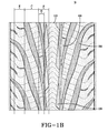
- FIG. 1 and FIG. 1B are plan views of a tread for a tire in accordance with the present invention.
- the tread configuration is intended for use on a passenger vehicle, or a light truck.
- the illustrated tread has a directional configuration, with the preferred direction for forward moving being that shown by the arrow D.
- the tread is divided into three regions, a central region A, and two side regions B.
- the central region is centered on the equatorial plane of the tire and has a width of approximately 15% to 30% of the tread width W, the tread width being measured from one tread shoulder to the opposing tread shoulder.
- the center of the tread is provided with a continuously extending rib 10.
- the rib 10 has sipes 12 extending across the full lateral width of the rib 10.
- the rib 10 has a heavy sipe density, within the range of 2 to 8 sipes per inch (0.78 to 3.15 sipes/cm), with a preferred density of 3 to 7 sipes per inch (1.18 to 2.76 sipes/cm).
- the presence of the rib 10 provides good ground contact of the tire, while the heavy siping of the rib 10, and thus the central region of the tire tread, provides for increased traction as the multiple sipes 12 flex open providing tread edges when the tread contacts the ground.
- the rib sipes 12 have a non-linear configuration of at least two inclined portions.
- the sipes 12 in FIG. 1 are formed of two inclined portions 14, 16.
- the inclined portions 14, 16 are placed at substantially similar, but oppositely inclined angles to form an inverse V configuration, wherein the apex of the V is located at approximately the equatorial plane EP of the tire.
- the spacing between circumferentially adjacent sipes 12 is constant, but may be varied to permit pitching of the tire for optimization of the noise characteristics of the tire.
- the sides 18, 20 of the rib 10 when viewed from above, have an extended, serrated configuration at the surface of the rib 10 that contacts the ground when the tread is new and not-worn.
- Each serration 22 is formed from a laterally oriented edge 24 and an inclined circumferentially extending edge 26; the junction of the two edges forming a serration point.
- the serrations 22 on each side 18, 20 of the rib 10 are laterally offset from each other.
- the laterally oriented edge 24 has a high inclination angle relative to the equatorial plane EP, while the circumferentially extending edge 26 has a low inclination angle relative to the equatorial plane EP.
- a chamfer 28 Extending from the laterally oriented edge 24 along each side 18, 20 of the rib 10 is a chamfer 28.
- the chamfer 28 extends in a circumferential direction from the laterally oriented edge 24 of the serration 22 to the next circumferentially adjacent serration 22, along the side 18, 20 of the rib 10.
- the chamfers 28 have a greatest width where the chamfer 28 initiates at the laterally oriented edge 24 of the serration 22.
- the width of the chamfer 28 narrows as the axially outermost edge 30 of the chamfer 28 is substantially parallel to the equatorial plane EP of the tire while the sides 18, 20 of the rib 10 are inclined in the circumferential direction.
- the provision of the chamfers 28 behind the heavily siped rib 10 provides support for the rib 10 as the sipes 12 flex open, strengthening the rib 10 and maintaining good ground contact pressure for the rib 10.
- FIG 2 illustrates a side view of the chamfer 28.
- the chamfer 28 has a maximum width at the laterally oriented edge 24 of the serration 22, and gradually decreases in width as the chamfer 28 approaches the next adjacent serration point.
- the height h of the chamfer 28 as measured from the base of the tread depth, gradually decreases in the circumferential direction, exposing the side wall 32 of the rib 10.
- FIG 3 illustrates a variation of the chamfer 28.
- the upper surface of the chamfer 28 is multi-planar. Where the chamfer 28 connects with the laterally oriented edge 24, the surface is defined by a radius of curvature R1 located inward of the upper surface of the chamfer 28. Towards the base of the chamfer 28, the top surface is defined by a radius of curvature R2 located outward of the upper surface of the chamfer 28.
- the chamfer 28 of FIG. 4 is a variation of that of FIG. 3 wherein a flat ledge 34 is employed along the mid-length of the chamfer 28.
- the chamfer 28 forms a tangency to a circle at several locations, as seen by R3 and R4.
- the top surface of the chamfer 28 has a different multi-planar configuration.
- the top surface of the chamfer 28 slopes downward toward the tread edge, see FIG. 5a.
- the axially outer edge 30 of the chamfer 28, relative to the equatorial plane EP of the tire gradually increases in height relative to the full tread depth.
- the axially inner edge 36 of the chamfer 28 decreases in height, see FIG. 5b.
- the width of the chamfer 28 decreases, the height increases, causing the outer surface of the chamfer 28 to twist.
- the sipes 12 in the center rib 10 may extend into the chamfers 28, see FIG. 6.
- the sipes 12 in the chamfers 28 do not open during rotation as there is no contact with the road surface, and the chamfer 28 continues to provide support to the rib 10.
- the effective rib width increases, and the siping of the chamfer 28 begins to interact with the remaining tread.
- sipes 12 in the chamfer 28 act as increased grooving of the tread as the tread depth decreases due to wear.
- the laterally oriented edge 24 of each serration 22 is inclined at an angle of equal or less than 90°, but no less than 45° relative to the equatorial plane EP.
- the laterally oriented edge 24 of each serration is inclined at approximately 45° relative to the equatorial plane EP.
- the laterally oriented edges 24 of each serration 22 on each side 18, 20 of the rib 10 are inclined as offset mirror images of the each other.
- the circumferentially extending edge 26 is inclined at angle of approximately 0° to 30° relative to the equatorial plane EP of the tire.
- the circumferentially extending edges 26 are substantially parallel to the EP, then the circumferentially adjacent laterally oriented edges 24 are inclined in opposing directions; or else the rib 10 will "walk” across the tread. Because the chamfers 28 extend from the laterally oriented edges 24, the chamfers 28 on each side 18, 20 of the rib 10 extend in the same direction.
- each side region B of the tread Adjacent to the center rib 10, in each side region B of the tread, are a plurality of steeply slanted grooves 38.
- the grooves 38 in each side region B of the tread are circumferentially offset from the grooves 38 in the opposing side region B.
- the grooves 38 initiate at the junction of the center region A and the side regions B.
- the grooves 38 have a very low angle of inclination relative to the EP of the tire tread, and gradually increase in inclination.
- the majority of each groove 38 has a inclination angle ⁇ of 20° to 50° relative to the circumferential direction of the tire, as measured by the centerline of the groove 38.
- the groove width varies. Close to the central rib 10, the groove width is relatively large, though partially consumed by the chafer 28, and as it traverses the side region, the width decreases and then widens out before decreasing again at the tread edge.
- the region of relatively greater width in the central portion of the groove 38 is located at approximately the mid-point of the side regions B.
- the portion of the groove 38 with the greatest width, as measured perpendicular to the groove centerline, has a maximum width Wx of 1.5 times the width Wn of the minimum groove width of the steeply slanted grooves 38.
- the inclination angle of the groove 38 increases, approaching 85°.
- the grooves have an angle of 70° - 85°.
- Circumferentially adjacent steeply slanted grooves 38 form circumferentially adjacent rib blocks 40.
- the blocks 40 initiate adjacent to the rib 10 and extend to the tread edge. At the tread edge, the block width increases.
- the blocks 40 extend continuously through the side regions B, however, if desired for increased water flow and traction, circumferential grooves may be provided in the side regions B to form smaller blocks.
- each chamfer 44 has a circumferential length of 1/60 th to 1/40 th of the circumferential length of the tire. Relative to the circumferential length of the associated tread block 40, the chamfer 44 has a length of 5% to 20% of the block length, the block length being measured along parallel to the equatorial plane and exclude the chamfer length.
- the chamfer 44 As the chamfer 44 extends into the junction of the grooves 38, the area of the grooves decreases with increased height of the chamfer 44. However, due to the positioning of the block chamfer 44 adjacent to the rib chamfers 38, the ability for water to flow into the grooves 38 is not compromised. As the rib chamfer 28 decreases in width and height, the block chamfer 44 increases in width and height. The placement of the circumferentially extending rib chamfers 28 in combination with the predominately circumferentially extending block chamfers 44 effectively approximate a pair of wide circumferential grooves. Thus, water flow in the tread is maintained, as is the stiffness of the central tread region.
- the rib chamfer 44 can have any of the chamfer profiles as shown in FIGS 2-5.
- the chamfer edge that decreases in height should be the axially outer edge, relative to the EP. By placing this edge as the outer edge, water is diverted into the grooves adjacent the rib 10.
- the net-to-gross ratio of the tread, and the various regions of the tread reflects the ability of the to move water.
- the center region has a net-to-gross ratio of 50 to 63% and each side region has a net-to-gross ratio of 55 to 70%.
- the zone F encompassing the effectively created wide circumferential grooves created by the adjacent chamfers, as measured from the axially innermost edge of the rib chamfer 28 and the axially outermost edge of the block chamfer 44 has a net-to-gross ratio of 22 to 35% when the tread is new. As the tread wears, this net-to-gross ratio increases. From the axially outermost edge of the block chamfer 44 to a location wherein the grooves 38 begin to decrease in width, the zone C, has a net-to-gross ratio of 50% to 65%.
- the axially outer edge of the tread, zone E has a net-to-gross ratio of 75% to 85%, typically for the tread edges of a tire to maintain tread edge stiffness. Extending from the tread edge toward the tread center, the net-to-gross ratio decreases until it reaches a maximum at the tread center due to the rib 10.
- Sipes 46 are spaced along the circumferential length of the block 40.
- the sipe density is the greatest toward the tread center and decreases in the direction of the tread edges.
- the sipe density has a maximum density of equal to the rib sipe density with a minimum density of 1 to 5 sipes per inch (0.393 - 1.97 sipes/cm).
- the sipe density is in the range of 0.5 to 3 sipes per inch (0.2 to 1.18 sipes/cm).
- the variation in the block sipe density cooperates with the high density siping in the tread rib 10 to gradually vary the tread stiffness. Additionally, as noted previously, the heavier siping in the center of the tread improves the snow driving performance of the tire by increasing the number of tread edges in the center of the tire while providing for a stiff tread at the outer tread zones.
- the sipes 46 extend into the tread shoulders. To assist in water drainage and flexibility at the tread edge, the sipes 46 may have increased width, as illustrated at FIG. 1.
- Each sipe 46 in the shoulder has a wide width portion 48 and a narrow width portion 50.
- the sipes 46 are arranged so that the wide width portions 48 and the narrow width portions 50 are circumferentially alternating.
- the steeply slanted grooves 38 in each side region B are mirror images, though laterally offset, of the steeply slanted grooves 38 in the opposing side region B. Also, due to the directional nature of the tread, all of the rib chamfers 28 are pointed in one direction and all the block chamfers 44 are pointed in the opposing direction.
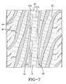
- FIG. 7 illustrates the previously described tire tread as a non-directional tire tread.
- the steeply slanted grooves 38 in each side region B are laterally offset mirror inverse images of the grooves 38 in the opposing side region B.
- the laterally oriented edges 24 of at the center one rib 10 are inclined in the same direction.
- the circumferentially extending edges 26 are inclined in the same direction, parallel to each other.
- the rib chamfers 28 on opposing sides of the rib 10 point in opposing directions, while the block chamfers 44 in each side region B point in the opposite direction from the block chamfers 44 in the opposing side region B.
- the sipes 52 in the rib 10 of the non-direction tread are formed of three portions, wherein the first and third portions 52A, 52B of the sipe 52 are inclined at substantially equal inclination angles.
- the block sipes 54 in the side regions B are inclined at angles substantially equal, but no more than 10° greater, than the rib sipe portion located adjacent to the relative side region.
- the overall sipe pattern for the entire tread is inclined at an angle opposite that of the steeply slanted grooves.
- non-direction tread may be identical to that of the directional tread, with permissible variations in accordance with those already discussed.
Landscapes
- Engineering & Computer Science (AREA)
- Mechanical Engineering (AREA)
- Tires In General (AREA)
Abstract
Description
- The present invention is directed to a tire tread with improved performance in snow and ice and in regular running conditions. The tread is provided with a central rib and a series of steeply slanted grooves adjacent the rib. The rib and the adjacent tread blocks are configured to provide for improved all weather performance.
- In a conventional tire for typical use as on a passenger car or light truck, the tire tread is provided with a series of grooves, either circumferentially or laterally extending, or a combination of both, to form a plurality of blocks.
- The goals of a tire during winter driving condition are to maintain good contact with the road, while providing for enhanced traction. However, since enhanced traction is best achieved by providing most biting edges to the tread pattern, while road contact is achieved by providing more surface area for tread contact, these goal are often conflicting.
- The present invention is directed to a tire with improved winter driving condition according to claim 1.
- The dependent claims cover preferred embodiments of the invention.
- In one aspect of the invention, at the axially inner portion of the block, the block has a sipe density of 1 to 5 sipes per inch (0.393 - 1.97 sipes/cm). At the axially outer portion of the block, the block has a sipe density of 0.5 to 3 sipes per inch (0.2 to 1.18 sipes/cm).
- In one aspect of the tire, the lateral edges of the rib have a plurality of laterally extending edges and circumferentially extending edges. The laterally extending edges on each side of the rib are circumferentially offset from the laterally extending edges on the opposing side of the ribs. Preferably, extending from the laterally oriented edges of the rib, and along the lateral edge of the rib, are chamfers that decrease in width from the laterally oriented edge to the circumferentially adjacent laterally oriented edge.
- In another aspect of the invention, the radial height of the rib chamfer gradually decreases from the laterally oriented edge to the circumferentially adjacent laterally oriented edge.
- In another disclosed aspect of the invention, to increase the rib flexibility as the tread wears, the sipes of the tread rib extend into the chamfers.
- The sipes in the tread rib are formed of at least two inclined portions. When formed of two portions, the sipe portions ideally follow the same inclination angle as the laterally oriented edges of the rib. In one embodiment, the sipes are formed of three portions.
- The sipes in the tread blocks are preferably oriented perpendicular to the steeply slanted grooves. The tread block sipes may also be inclined in the same direction as the most adjacent sipe portion of the tread rib.
- In another aspect of the tire, the steeply slanted grooves have a non-constant width as the grooves extend from the central region to the shoulders, the grooves having a maximum width in the central 15% of each side region of the tread. The grooves may have a maximum width of at least 1.5 times the minimum groove width of the steeply slanted grooves.
- In another aspect of the invention, the net-to-gross ratio of the tire decreases from the tread edge toward the tread center, with a maximum net-to-gross ratio at the equatorial plane of the tire.
- The invention will be described by way of example and with reference to the accompanying drawings in which:
- FIG. 1 and FIG. 1B are plan views of the tire;
- FIGS. 2 - 5 are various embodiments of the rib chamfers;
- FIGS. 5a - 5b are cross sectional views taken of the chamfer of FIG. 5;
- FIG. 6 is a portion of the rib and a chamfer illustrating another embodiment of the siping; and
- FIG. 7 is another alternative of the tread.
- FIG. 1 and FIG. 1B are plan views of a tread for a tire in accordance with the present invention. The tread configuration is intended for use on a passenger vehicle, or a light truck. The illustrated tread has a directional configuration, with the preferred direction for forward moving being that shown by the arrow D. The tread is divided into three regions, a central region A, and two side regions B. The central region is centered on the equatorial plane of the tire and has a width of approximately 15% to 30% of the tread width W, the tread width being measured from one tread shoulder to the opposing tread shoulder.
- When operating in winter driving conditions, the central region of the tire has the most impact on the performance of the tire. In the present tire tread, the center of the tread is provided with a continuously extending
rib 10. Therib 10 hassipes 12 extending across the full lateral width of therib 10. Therib 10 has a heavy sipe density, within the range of 2 to 8 sipes per inch (0.78 to 3.15 sipes/cm), with a preferred density of 3 to 7 sipes per inch (1.18 to 2.76 sipes/cm). The presence of therib 10 provides good ground contact of the tire, while the heavy siping of therib 10, and thus the central region of the tire tread, provides for increased traction as themultiple sipes 12 flex open providing tread edges when the tread contacts the ground. - The
rib sipes 12 have a non-linear configuration of at least two inclined portions. Thesipes 12 in FIG. 1 are formed of twoinclined portions inclined portions adjacent sipes 12 is constant, but may be varied to permit pitching of the tire for optimization of the noise characteristics of the tire. - The
sides rib 10, when viewed from above, have an extended, serrated configuration at the surface of therib 10 that contacts the ground when the tread is new and not-worn. Eachserration 22 is formed from a laterallyoriented edge 24 and an inclined circumferentially extendingedge 26; the junction of the two edges forming a serration point. Theserrations 22 on eachside rib 10 are laterally offset from each other. The laterallyoriented edge 24 has a high inclination angle relative to the equatorial plane EP, while the circumferentially extendingedge 26 has a low inclination angle relative to the equatorial plane EP. - Extending from the laterally oriented
edge 24 along eachside rib 10 is achamfer 28. Thechamfer 28 extends in a circumferential direction from the laterallyoriented edge 24 of theserration 22 to the next circumferentiallyadjacent serration 22, along theside rib 10. - Due to the
chamfer 28, at the tread depth therib 10 has an almost straight configuration. Thechamfers 28 have a greatest width where thechamfer 28 initiates at the laterally orientededge 24 of theserration 22. The width of thechamfer 28 narrows as the axiallyoutermost edge 30 of thechamfer 28 is substantially parallel to the equatorial plane EP of the tire while thesides rib 10 are inclined in the circumferential direction. The provision of thechamfers 28 behind the heavily sipedrib 10 provides support for therib 10 as thesipes 12 flex open, strengthening therib 10 and maintaining good ground contact pressure for therib 10. - FIG 2 illustrates a side view of the
chamfer 28. Thechamfer 28 has a maximum width at the laterally orientededge 24 of theserration 22, and gradually decreases in width as thechamfer 28 approaches the next adjacent serration point. Concurrently, the height h of thechamfer 28, as measured from the base of the tread depth, gradually decreases in the circumferential direction, exposing theside wall 32 of therib 10. - FIG 3 illustrates a variation of the
chamfer 28. The upper surface of thechamfer 28 is multi-planar. Where thechamfer 28 connects with the laterally orientededge 24, the surface is defined by a radius of curvature R1 located inward of the upper surface of thechamfer 28. Towards the base of thechamfer 28, the top surface is defined by a radius of curvature R2 located outward of the upper surface of thechamfer 28. - The
chamfer 28 of FIG. 4 is a variation of that of FIG. 3 wherein aflat ledge 34 is employed along the mid-length of thechamfer 28. Thechamfer 28 forms a tangency to a circle at several locations, as seen by R3 and R4. - In another embodiment of the
chamfer 28, FIG. 5, the top surface of thechamfer 28 has a different multi-planar configuration. At the maximum lateral width, the top surface of thechamfer 28 slopes downward toward the tread edge, see FIG. 5a. As the chamfer width decreases, the axiallyouter edge 30 of thechamfer 28, relative to the equatorial plane EP of the tire, gradually increases in height relative to the full tread depth. Concurrently, the axiallyinner edge 36 of thechamfer 28 decreases in height, see FIG. 5b. Thus, as the width of thechamfer 28 decreases, the height increases, causing the outer surface of thechamfer 28 to twist. - If maintaining tread flexibility as the tread is worn is desired, the
sipes 12 in thecenter rib 10 may extend into thechamfers 28, see FIG. 6. When the tread is unworn, thesipes 12 in thechamfers 28 do not open during rotation as there is no contact with the road surface, and thechamfer 28 continues to provide support to therib 10. After the tread begins to wear, and the uppermost surface of thechamfer 28 slowly becomes part of the ground contacting surface of the tread, the effective rib width increases, and the siping of thechamfer 28 begins to interact with the remaining tread. In effect,sipes 12 in thechamfer 28 act as increased grooving of the tread as the tread depth decreases due to wear. - The laterally oriented
edge 24 of eachserration 22 is inclined at an angle of equal or less than 90°, but no less than 45° relative to the equatorial plane EP. In the tread of FIG. 1, the laterally orientededge 24 of each serration is inclined at approximately 45° relative to the equatorial plane EP. The laterally orientededges 24 of eachserration 22 on eachside rib 10 are inclined as offset mirror images of the each other. Thecircumferentially extending edge 26 is inclined at angle of approximately 0° to 30° relative to the equatorial plane EP of the tire. When thecircumferentially extending edges 26 are substantially parallel to the EP, then the circumferentially adjacent laterally orientededges 24 are inclined in opposing directions; or else therib 10 will "walk" across the tread. Because thechamfers 28 extend from the laterally orientededges 24, thechamfers 28 on eachside rib 10 extend in the same direction. - Adjacent to the
center rib 10, in each side region B of the tread, are a plurality of steeply slantedgrooves 38. Thegrooves 38 in each side region B of the tread are circumferentially offset from thegrooves 38 in the opposing side region B. Thegrooves 38 initiate at the junction of the center region A and the side regions B. At the junction, thegrooves 38 have a very low angle of inclination relative to the EP of the tire tread, and gradually increase in inclination. The majority of eachgroove 38 has a inclination angle α of 20° to 50° relative to the circumferential direction of the tire, as measured by the centerline of thegroove 38. - As the
grooves 38 traverse the side regions B of the tread, the groove width varies. Close to thecentral rib 10, the groove width is relatively large, though partially consumed by thechafer 28, and as it traverses the side region, the width decreases and then widens out before decreasing again at the tread edge. The region of relatively greater width in the central portion of thegroove 38 is located at approximately the mid-point of the side regions B. The portion of thegroove 38 with the greatest width, as measured perpendicular to the groove centerline, has a maximum width Wx of 1.5 times the width Wn of the minimum groove width of the steeply slantedgrooves 38. - As the tread edge, the inclination angle of the
groove 38 increases, approaching 85°. At the tread edge, the grooves have an angle of 70° - 85°. - Circumferentially adjacent steeply slanted
grooves 38 form circumferentially adjacent rib blocks 40. Theblocks 40 initiate adjacent to therib 10 and extend to the tread edge. At the tread edge, the block width increases. Theblocks 40 extend continuously through the side regions B, however, if desired for increased water flow and traction, circumferential grooves may be provided in the side regions B to form smaller blocks. - At the axially
innermost edge 42 of theblocks 40, and extending into the junction of adjacent steeply slantedgrooves 38, are extendingsloping chamfers 44. Eachchamfer 44 has a circumferential length of 1/60th to 1/40th of the circumferential length of the tire. Relative to the circumferential length of the associatedtread block 40, thechamfer 44 has a length of 5% to 20% of the block length, the block length being measured along parallel to the equatorial plane and exclude the chamfer length. - As the
chamfer 44 extends into the junction of thegrooves 38, the area of the grooves decreases with increased height of thechamfer 44. However, due to the positioning of theblock chamfer 44 adjacent to the rib chamfers 38, the ability for water to flow into thegrooves 38 is not compromised. As therib chamfer 28 decreases in width and height, theblock chamfer 44 increases in width and height. The placement of the circumferentially extendingrib chamfers 28 in combination with the predominately circumferentially extendingblock chamfers 44 effectively approximate a pair of wide circumferential grooves. Thus, water flow in the tread is maintained, as is the stiffness of the central tread region. - The
rib chamfer 44 can have any of the chamfer profiles as shown in FIGS 2-5. When the chamfer of FIG. 5 is used as therib chamfer 44, the chamfer edge that decreases in height should be the axially outer edge, relative to the EP. By placing this edge as the outer edge, water is diverted into the grooves adjacent therib 10. - The net-to-gross ratio of the tread, and the various regions of the tread, reflects the ability of the to move water. When viewed with just two zones, as illustrated in FIG. 1, the center region has a net-to-gross ratio of 50 to 63% and each side region has a net-to-gross ratio of 55 to 70%.
- To more fully appreciate the water flow capability of the tread, additional zones may be identified in each tread half. The zone F encompassing the effectively created wide circumferential grooves created by the adjacent chamfers, as measured from the axially innermost edge of the
rib chamfer 28 and the axially outermost edge of theblock chamfer 44 has a net-to-gross ratio of 22 to 35% when the tread is new. As the tread wears, this net-to-gross ratio increases. From the axially outermost edge of theblock chamfer 44 to a location wherein thegrooves 38 begin to decrease in width, the zone C, has a net-to-gross ratio of 50% to 65%. The axially outer edge of the tread, zone E, has a net-to-gross ratio of 75% to 85%, typically for the tread edges of a tire to maintain tread edge stiffness. Extending from the tread edge toward the tread center, the net-to-gross ratio decreases until it reaches a maximum at the tread center due to therib 10. -
Sipes 46 are spaced along the circumferential length of theblock 40. The sipe density is the greatest toward the tread center and decreases in the direction of the tread edges. At the axially inner portion of theblock 40, the sipe density has a maximum density of equal to the rib sipe density with a minimum density of 1 to 5 sipes per inch (0.393 - 1.97 sipes/cm). At the axially outer portion of theblock 40, the sipe density is in the range of 0.5 to 3 sipes per inch (0.2 to 1.18 sipes/cm). The variation in the block sipe density cooperates with the high density siping in thetread rib 10 to gradually vary the tread stiffness. Additionally, as noted previously, the heavier siping in the center of the tread improves the snow driving performance of the tire by increasing the number of tread edges in the center of the tire while providing for a stiff tread at the outer tread zones. - At the axially outermost 25% of the each side region B, the
sipes 46 extend into the tread shoulders. To assist in water drainage and flexibility at the tread edge, thesipes 46 may have increased width, as illustrated at FIG. 1. Eachsipe 46 in the shoulder has awide width portion 48 and anarrow width portion 50. In each block, thesipes 46 are arranged so that thewide width portions 48 and thenarrow width portions 50 are circumferentially alternating. - For the directional tread illustrated in FIG. 1, the steeply slanted
grooves 38 in each side region B are mirror images, though laterally offset, of the steeply slantedgrooves 38 in the opposing side region B. Also, due to the directional nature of the tread, all of the rib chamfers 28 are pointed in one direction and all the block chamfers 44 are pointed in the opposing direction. - FIG. 7 illustrates the previously described tire tread as a non-directional tire tread. The steeply slanted
grooves 38 in each side region B are laterally offset mirror inverse images of thegrooves 38 in the opposing side region B. The laterally orientededges 24 of at the center onerib 10 are inclined in the same direction. To maintain the serrated configuration, thecircumferentially extending edges 26 are inclined in the same direction, parallel to each other. The rib chamfers 28 on opposing sides of therib 10 point in opposing directions, while the block chamfers 44 in each side region B point in the opposite direction from the block chamfers 44 in the opposing side region B. - The
sipes 52 in therib 10 of the non-direction tread are formed of three portions, wherein the first andthird portions sipe 52 are inclined at substantially equal inclination angles. The block sipes 54 in the side regions B are inclined at angles substantially equal, but no more than 10° greater, than the rib sipe portion located adjacent to the relative side region. In the instant tread, the overall sipe pattern for the entire tread is inclined at an angle opposite that of the steeply slanted grooves. - Other features of the non-direction tread may be identical to that of the directional tread, with permissible variations in accordance with those already discussed.
Claims (8)
- A pneumatic tire comprising a tread and shoulders adjacent the tread, the tread comprising a central region (A) and a pair of opposing side regions (B), the tread further comprising a circumferentially extending rib (10) in the central region (A), and a plurality of steeply slanted grooves (38) inclined at an angle relative to the circumferential direction of the tire in each side region (B),
the steeply slanted grooves (38) in each side region (B) initiate at the junction of the central region (A) and the side regions (B) and preferably terminate in the shoulders, forming circumferentially adjacent tread blocks (40), the blocks (40) extending from the central region (A) to the side regions (B) or the shoulders, and having a plurality of sipes (46,54),
the tread being characterized by:the rib (10) having a plurality of sipes (12) extending across the full width of the rib (10), the sipes (12) having a density of 2 to 8 sipes per inch (0.78-3.15 sipes per cm),the spacing between adjacent sipes (12) in the blocks (40) increasing toward the tread shoulders, andthe tread having a greater sipe density in the central region (A) of the tire than in the side regions (B). - The tire of claim 1 wherein the sipes (12) in the tread rib (10) are comprised of at least two inclined portions (14, 16).
- The tire of claim 1 or 2, wherein the sipes (46, 54) in the blocks (40) are oriented perpendicular to the steeply slanted grooves (38).
- The tire of at least one of the previous claims, wherein the sipes (12) in the tread rib (10) have two sections formed of portions inclined at equal but opposing angles and the sipes (46, 54) in the blocks (40) are inclined in the same direction as the most adjacent sipe portion in the tread rib (10).
- The tire of at least one of the previous claims, wherein the sipes (46, 54) in the axially outermost 25% of each side region (B) extend into the tread shoulders.
- The tire of at least one of the previous claims, wherein each sipe (46, 54) extending into the shoulder has a wide and a narrow width portion (48, 50) such that the wide width portion (48) of each sipe in a single block is circumferentially adjacent to a narrow width portion (50) of the adjacent block.
- The tire of at least one of the previous claims, wherein at the axially inner portion of the block (40), the block (40) has a sipe density of 1 to 5 sipes per inch (0.393 - 1.97 sipes/cm) and at the axially outer portion of the block (40), the block (40) has a sipe density of 0.5 to 3 sipes per inch (0.2 to 1.18 sipes/cm).
- The tire of at least one of the previous claims, wherein the net-to-gross ratio of the tire decreases from the tread edge toward the tread center, with a maximum net-to-gross ratio at the equatorial plane (EP) of the tire.
Applications Claiming Priority (2)
| Application Number | Priority Date | Filing Date | Title |
|---|---|---|---|
| US601504 | 1995-07-19 | ||
| US10/601,504 US6968881B2 (en) | 2003-06-23 | 2003-06-23 | Pneumatic tire including steeply slanted grooves, rib having sipes and blocks having sipes |
Publications (2)
| Publication Number | Publication Date |
|---|---|
| EP1491367A1 true EP1491367A1 (en) | 2004-12-29 |
| EP1491367B1 EP1491367B1 (en) | 2007-02-21 |
Family
ID=33418596
Family Applications (1)
| Application Number | Title | Priority Date | Filing Date |
|---|---|---|---|
| EP04102672A Expired - Lifetime EP1491367B1 (en) | 2003-06-23 | 2004-06-14 | Tire tread |
Country Status (5)
| Country | Link |
|---|---|
| US (1) | US6968881B2 (en) |
| EP (1) | EP1491367B1 (en) |
| BR (1) | BRPI0401967B1 (en) |
| CA (1) | CA2471995C (en) |
| DE (1) | DE602004004837T2 (en) |
Families Citing this family (29)
| Publication number | Priority date | Publication date | Assignee | Title |
|---|---|---|---|---|
| US7143798B2 (en) * | 2003-06-23 | 2006-12-05 | The Goodyear Tire & Rubber Company | Pneumatic tire having tread with axially adjacent block chamfer and rib chamfer |
| US7028733B2 (en) * | 2003-06-23 | 2006-04-18 | The Goodyear Tire & Rubber Company | Pneumatic tire having circumferentially extending rib with chamfers |
| USD519916S1 (en) * | 2004-06-15 | 2006-05-02 | The Goodyear Tire & Rubber Company | Shoulder tread for a tire |
| USD534859S1 (en) * | 2005-12-19 | 2007-01-09 | The Goodyear Tire & Rubber Company | Tire tread |
| USD535248S1 (en) * | 2006-01-27 | 2007-01-16 | The Goodyear Tire & Rubber Company | Tire tread |
| USD535247S1 (en) * | 2006-01-27 | 2007-01-16 | The Goodyear Tire & Rubber Company | Tire tread |
| USD534482S1 (en) * | 2006-01-27 | 2007-01-02 | The Goodyear Tire & Rubber Company | Tire tread |
| USD589435S1 (en) | 2006-10-05 | 2009-03-31 | The Goodyear Tire & Rubber Company | Tire tread |
| US7874331B2 (en) * | 2007-03-02 | 2011-01-25 | The Goodyear Tire & Rubber Company | Pneumatic tire with tread having chamfer located in notch |
| US20090194212A1 (en) * | 2008-02-01 | 2009-08-06 | Mark Leonard Bonko | Tire tread discharge grooves with textured bases |
| US20090194211A1 (en) * | 2008-02-01 | 2009-08-06 | John Alan Howald | Tire tread grooves with textured bases |
| USD579862S1 (en) | 2008-02-14 | 2008-11-04 | The Goodyear Tire & Rubber Company | Tire |
| USD607811S1 (en) | 2008-07-25 | 2010-01-12 | The Goodyear Tire & Rubber Company | Tire |
| CN102666135B (en) * | 2009-11-23 | 2015-12-16 | 米其林集团总公司 | There is the tire of the side groove with the chamfering for improving snowfield performance |
| USD616807S1 (en) | 2009-12-11 | 2010-06-01 | The Goodyear Tire & Rubber Company | Tire |
| US8393365B2 (en) * | 2009-12-11 | 2013-03-12 | The Goodyear Tire & Rubber Company | Tire tread having serrated grooves |
| USD616808S1 (en) | 2009-12-11 | 2010-06-01 | The Goodyear Tire & Rubber Company | Tire |
| USD616809S1 (en) | 2010-01-13 | 2010-06-01 | The Goodyear Tire & Rubber Company | Tire |
| USD624872S1 (en) | 2010-01-13 | 2010-10-05 | The Goodyear Tire & Rubber Company | Tire |
| USD633434S1 (en) | 2010-08-31 | 2011-03-01 | The Goodyear Tire & Rubber Company | Tire |
| FR3012768B1 (en) * | 2013-11-05 | 2016-12-23 | Michelin & Cie | ROLLER BAND COMPRISING A BLOCK HAVING A PLURALITY OF INCISIONS |
| FR3012767B1 (en) * | 2013-11-05 | 2015-10-23 | Michelin & Cie | ROLLER BAND COMPRISING A BLOCK HAVING A PLURALITY OF INCISIONS |
| MX376096B (en) | 2014-06-19 | 2025-03-07 | Pirelli | CAR TIRE. |
| JP6790663B2 (en) * | 2016-09-26 | 2020-11-25 | 住友ゴム工業株式会社 | tire |
| JP2019131081A (en) * | 2018-01-31 | 2019-08-08 | Toyo Tire株式会社 | Pneumatic tire |
| US11472232B2 (en) | 2019-12-18 | 2022-10-18 | The Goodyear Tire & Rubber Company | Tire with tread elements including dual angled chamfer |
| JP7170769B2 (en) * | 2021-03-18 | 2022-11-14 | Toyo Tire株式会社 | pneumatic tire |
| FI4461567T3 (en) * | 2023-05-08 | 2026-01-02 | Nokian Renkaat Oyj | Studded tire with sipe grooves |
| EP4461568B1 (en) * | 2023-05-08 | 2025-07-02 | Nokian Renkaat Oyj | A studded tyre having grooves |
Citations (3)
| Publication number | Priority date | Publication date | Assignee | Title |
|---|---|---|---|---|
| EP0882606A2 (en) * | 1997-06-02 | 1998-12-09 | Bridgestone Corporation | Pneumatic tyre |
| EP1090781A2 (en) * | 1999-10-06 | 2001-04-11 | Sumitomo Rubber Industries Limited | Studless tyre |
| US20010017177A1 (en) * | 2000-02-16 | 2001-08-30 | Bridgestone Corporation | Pneumatic tires |
Family Cites Families (35)
| Publication number | Priority date | Publication date | Assignee | Title |
|---|---|---|---|---|
| DE2455130A1 (en) | 1974-11-21 | 1976-05-26 | Continental Gummi Werke Ag | PNEUMATIC TIRES FOR MOTOR VEHICLES |
| US4641695A (en) | 1984-07-18 | 1987-02-10 | The Goodyear Tire & Rubber Company | Tread for a pneumatic tire |
| EP0172974B1 (en) | 1984-08-28 | 1988-04-27 | The Goodyear Tire & Rubber Company | A pneumatic tire |
| JPH0692201B2 (en) | 1986-03-14 | 1994-11-16 | 株式会社ブリヂストン | Pneumatic radial tire for high speed |
| GB2192842B (en) | 1986-06-13 | 1991-01-30 | Bridgestone Corp | Pneumatic tire |
| JPH02179508A (en) * | 1988-12-29 | 1990-07-12 | Yokohama Rubber Co Ltd:The | Pneumatic tire |
| JP2824680B2 (en) * | 1989-12-18 | 1998-11-11 | 横浜ゴム株式会社 | Pneumatic tires for icy and snowy roads |
| CA2023538C (en) * | 1990-05-17 | 2000-01-11 | Jean Francois Leon Fontaine | Tread for a pneumatic tire |
| USD358793S (en) | 1993-04-30 | 1995-05-30 | Bridgestone Corporation | Automobile tire |
| JP3380605B2 (en) | 1993-05-20 | 2003-02-24 | 株式会社ブリヂストン | Pneumatic tire |
| USD366020S (en) | 1993-07-30 | 1996-01-09 | Bridgestone Corporation | Automobile tire |
| DE69518470T2 (en) * | 1994-06-23 | 2001-05-23 | Bridgestone Corp., Tokio/Tokyo | tire |
| JP3388902B2 (en) | 1994-09-20 | 2003-03-24 | 株式会社ブリヂストン | Pneumatic radial tire |
| JP3555777B2 (en) | 1994-11-22 | 2004-08-18 | 株式会社ブリヂストン | High performance pneumatic tire with directional sloping grooves |
| FR2748696B1 (en) | 1996-05-20 | 1999-12-31 | Bridgestone Corp | PNEUMATIC TAPE WITH ASYMMETRICAL DIRECTIONAL DESIGN IN PARTICULAR FOR A RACE CAR |
| JP3542687B2 (en) | 1996-06-11 | 2004-07-14 | 株式会社ブリヂストン | Pneumatic tire |
| US6213180B1 (en) | 1997-03-26 | 2001-04-10 | Bridgestone Corporation | Pneumatic radial tire including beveled acute angle corner portions |
| JP3958426B2 (en) | 1998-01-14 | 2007-08-15 | 株式会社ブリヂストン | Pneumatic radial tire for passenger cars with directional inclined grooves |
| JP3337415B2 (en) * | 1998-03-04 | 2002-10-21 | 住友ゴム工業株式会社 | Pneumatic tire suitable for running on ice |
| USD416836S (en) | 1998-06-25 | 1999-11-23 | Bridgestone Corporation | Automobile tire |
| DE60036168T2 (en) * | 1999-02-26 | 2008-05-15 | Bridgestone Corp. | TIRE |
| USD423996S (en) | 1999-06-01 | 2000-05-02 | Michelin Recherche Et Technique S.A. | Split screw tire tread |
| USD423425S (en) | 1999-06-01 | 2000-04-25 | Michelin Recherche Et Technique S.A. | Split screw tire tread |
| USD432057S (en) | 1999-06-25 | 2000-10-17 | Bridgestone Corporation | Automobile tire |
| ATE330402T1 (en) | 1999-08-31 | 2006-07-15 | Canon Kk | INFORMATION SIGNAL PROCESSING APPARATUS, ASSOCIATED SYSTEM, ASSOCIATED METHOD AND ASSOCIATED STORAGE MEDIUM |
| USD445730S1 (en) | 1999-12-27 | 2001-07-31 | Bridgestone Corporation | Automobile tire |
| US6520230B1 (en) | 2000-09-06 | 2003-02-18 | The Goodyear Tire & Rubber Company | Tire with an open tread |
| JP4716551B2 (en) * | 2000-10-03 | 2011-07-06 | 株式会社ブリヂストン | Pneumatic tires for winter |
| USD454833S1 (en) | 2000-11-08 | 2002-03-26 | Michelin Recherche Et Technique S.A. | Tire tread |
| JPWO2002062892A1 (en) | 2001-02-02 | 2004-10-21 | 出光興産株式会社 | Resin composition for toner and toner |
| JP2002240513A (en) * | 2001-02-20 | 2002-08-28 | Bridgestone Corp | Pneumatic tire |
| ATE319579T1 (en) * | 2001-08-03 | 2006-03-15 | Pirelli | TIRE ESPECIALLY SUITABLE FOR SNOW-COVERED GROUND |
| US6983777B2 (en) * | 2002-10-15 | 2006-01-10 | The Goodyear Tire & Rubber Company | Tire tread with multi-planar chamfers |
| US7028733B2 (en) * | 2003-06-23 | 2006-04-18 | The Goodyear Tire & Rubber Company | Pneumatic tire having circumferentially extending rib with chamfers |
| US7143798B2 (en) * | 2003-06-23 | 2006-12-05 | The Goodyear Tire & Rubber Company | Pneumatic tire having tread with axially adjacent block chamfer and rib chamfer |
-
2003
- 2003-06-23 US US10/601,504 patent/US6968881B2/en not_active Expired - Lifetime
-
2004
- 2004-06-14 EP EP04102672A patent/EP1491367B1/en not_active Expired - Lifetime
- 2004-06-14 DE DE602004004837T patent/DE602004004837T2/en not_active Expired - Lifetime
- 2004-06-16 BR BRPI0401967-9B1A patent/BRPI0401967B1/en not_active IP Right Cessation
- 2004-06-22 CA CA2471995A patent/CA2471995C/en not_active Expired - Fee Related
Patent Citations (3)
| Publication number | Priority date | Publication date | Assignee | Title |
|---|---|---|---|---|
| EP0882606A2 (en) * | 1997-06-02 | 1998-12-09 | Bridgestone Corporation | Pneumatic tyre |
| EP1090781A2 (en) * | 1999-10-06 | 2001-04-11 | Sumitomo Rubber Industries Limited | Studless tyre |
| US20010017177A1 (en) * | 2000-02-16 | 2001-08-30 | Bridgestone Corporation | Pneumatic tires |
Also Published As
| Publication number | Publication date |
|---|---|
| DE602004004837T2 (en) | 2007-11-15 |
| EP1491367B1 (en) | 2007-02-21 |
| CA2471995A1 (en) | 2004-12-23 |
| DE602004004837D1 (en) | 2007-04-05 |
| US20040256039A1 (en) | 2004-12-23 |
| BRPI0401967A (en) | 2005-02-01 |
| US6968881B2 (en) | 2005-11-29 |
| BRPI0401967B1 (en) | 2013-07-16 |
| CA2471995C (en) | 2011-10-18 |
Similar Documents
| Publication | Publication Date | Title |
|---|---|---|
| EP1491367B1 (en) | Tire tread | |
| EP1491366B1 (en) | Tire tread | |
| EP1498290B1 (en) | Tire tread | |
| US6983777B2 (en) | Tire tread with multi-planar chamfers | |
| EP1987965B1 (en) | Pneumatic tire | |
| EP1935671B1 (en) | Pneumatic tire | |
| EP0812709B1 (en) | Pneumatic tires | |
| US5152854A (en) | Pneumatic tire having directional tread | |
| JP2732794B2 (en) | tire | |
| KR101101042B1 (en) | Tread for pneumatic tires | |
| EP1995080B1 (en) | Pneumatic tire | |
| EP0069464A2 (en) | Tyre treads | |
| EP3017964A1 (en) | An improved tread for a snow tire | |
| EP1935670B1 (en) | Pneumatic tire | |
| JPH10230712A (en) | Pneumatic radial tires for all season passenger cars | |
| EP1093939B1 (en) | An on/off road tread for a tire | |
| CA1324070C (en) | Pneumatic tire | |
| EP3332990B1 (en) | Tire tread for a snow tire | |
| JPH09188110A (en) | Pneumatic radial tire for heavy loads | |
| JPH1120413A (en) | Pneumatic radial tires for all season passenger cars | |
| JP2000247112A (en) | Pneumatic tire | |
| JPH0867114A (en) | Pneumatic tire suitable for running on snow and ice | |
| JP2004338628A (en) | Pneumatic tire | |
| EP0540339B1 (en) | Pneumatic tire | |
| JPH092024A (en) | High athletic performance pneumatic tire with directional tilt block |
Legal Events
| Date | Code | Title | Description |
|---|---|---|---|
| PUAI | Public reference made under article 153(3) epc to a published international application that has entered the european phase |
Free format text: ORIGINAL CODE: 0009012 |
|
| AK | Designated contracting states |
Kind code of ref document: A1 Designated state(s): AT BE BG CH CY CZ DE DK EE ES FI FR GB GR HU IE IT LI LU MC NL PL PT RO SE SI SK TR |
|
| AX | Request for extension of the european patent |
Extension state: AL HR LT LV MK |
|
| 17P | Request for examination filed |
Effective date: 20050629 |
|
| AKX | Designation fees paid |
Designated state(s): DE FR GB IT |
|
| GRAP | Despatch of communication of intention to grant a patent |
Free format text: ORIGINAL CODE: EPIDOSNIGR1 |
|
| RIN1 | Information on inventor provided before grant (corrected) |
Inventor name: RATLIFF, BILLY JOE, JR Inventor name: LANDERS, SAMUEL PATRICK Inventor name: POLING, DAVID CHARLES Inventor name: SCHMALIX, CHARLES KENNETH Inventor name: LOSEY, ROBERT ALLEN |
|
| GRAS | Grant fee paid |
Free format text: ORIGINAL CODE: EPIDOSNIGR3 |
|
| GRAA | (expected) grant |
Free format text: ORIGINAL CODE: 0009210 |
|
| AK | Designated contracting states |
Kind code of ref document: B1 Designated state(s): DE FR GB IT |
|
| REG | Reference to a national code |
Ref country code: GB Ref legal event code: FG4D |
|
| REF | Corresponds to: |
Ref document number: 602004004837 Country of ref document: DE Date of ref document: 20070405 Kind code of ref document: P |
|
| PLBE | No opposition filed within time limit |
Free format text: ORIGINAL CODE: 0009261 |
|
| STAA | Information on the status of an ep patent application or granted ep patent |
Free format text: STATUS: NO OPPOSITION FILED WITHIN TIME LIMIT |
|
| 26N | No opposition filed |
Effective date: 20071122 |
|
| PGFP | Annual fee paid to national office [announced via postgrant information from national office to epo] |
Ref country code: GB Payment date: 20080506 Year of fee payment: 5 |
|
| GBPC | Gb: european patent ceased through non-payment of renewal fee |
Effective date: 20090614 |
|
| REG | Reference to a national code |
Ref country code: FR Ref legal event code: ST Effective date: 20100226 |
|
| PG25 | Lapsed in a contracting state [announced via postgrant information from national office to epo] |
Ref country code: FR Free format text: LAPSE BECAUSE OF NON-PAYMENT OF DUE FEES Effective date: 20090630 |
|
| REG | Reference to a national code |
Ref country code: FR Ref legal event code: D3 |
|
| PG25 | Lapsed in a contracting state [announced via postgrant information from national office to epo] |
Ref country code: GB Free format text: LAPSE BECAUSE OF NON-PAYMENT OF DUE FEES Effective date: 20090614 |
|
| PGRI | Patent reinstated in contracting state [announced from national office to epo] |
Ref country code: FR Effective date: 20100413 |
|
| REG | Reference to a national code |
Ref country code: FR Ref legal event code: PLFP Year of fee payment: 13 |
|
| REG | Reference to a national code |
Ref country code: FR Ref legal event code: PLFP Year of fee payment: 14 |
|
| REG | Reference to a national code |
Ref country code: FR Ref legal event code: PLFP Year of fee payment: 15 |
|
| PGFP | Annual fee paid to national office [announced via postgrant information from national office to epo] |
Ref country code: DE Payment date: 20180530 Year of fee payment: 15 |
|
| PGFP | Annual fee paid to national office [announced via postgrant information from national office to epo] |
Ref country code: IT Payment date: 20180625 Year of fee payment: 15 |
|
| REG | Reference to a national code |
Ref country code: DE Ref legal event code: R119 Ref document number: 602004004837 Country of ref document: DE |
|
| PG25 | Lapsed in a contracting state [announced via postgrant information from national office to epo] |
Ref country code: DE Free format text: LAPSE BECAUSE OF NON-PAYMENT OF DUE FEES Effective date: 20200101 Ref country code: IT Free format text: LAPSE BECAUSE OF NON-PAYMENT OF DUE FEES Effective date: 20190614 |
|
| REG | Reference to a national code |
Ref country code: FR Ref legal event code: PLFP Year of fee payment: 20 |
|
| PGFP | Annual fee paid to national office [announced via postgrant information from national office to epo] |
Ref country code: FR Payment date: 20230411 Year of fee payment: 20 |