EP1491307A1 - Method of drying honeycomb formed body - Google Patents
Method of drying honeycomb formed body Download PDFInfo
- Publication number
- EP1491307A1 EP1491307A1 EP03705048A EP03705048A EP1491307A1 EP 1491307 A1 EP1491307 A1 EP 1491307A1 EP 03705048 A EP03705048 A EP 03705048A EP 03705048 A EP03705048 A EP 03705048A EP 1491307 A1 EP1491307 A1 EP 1491307A1
- Authority
- EP
- European Patent Office
- Prior art keywords
- wall
- drying
- formed body
- honeycomb formed
- guide
- Prior art date
- Legal status (The legal status is an assumption and is not a legal conclusion. Google has not performed a legal analysis and makes no representation as to the accuracy of the status listed.)
- Granted
Links
Images



Classifications
-
- C—CHEMISTRY; METALLURGY
- C04—CEMENTS; CONCRETE; ARTIFICIAL STONE; CERAMICS; REFRACTORIES
- C04B—LIME, MAGNESIA; SLAG; CEMENTS; COMPOSITIONS THEREOF, e.g. MORTARS, CONCRETE OR LIKE BUILDING MATERIALS; ARTIFICIAL STONE; CERAMICS; REFRACTORIES; TREATMENT OF NATURAL STONE
- C04B35/00—Shaped ceramic products characterised by their composition; Ceramics compositions; Processing powders of inorganic compounds preparatory to the manufacturing of ceramic products
- C04B35/622—Forming processes; Processing powders of inorganic compounds preparatory to the manufacturing of ceramic products
- C04B35/626—Preparing or treating the powders individually or as batches ; preparing or treating macroscopic reinforcing agents for ceramic products, e.g. fibres; mechanical aspects section B
- C04B35/63—Preparing or treating the powders individually or as batches ; preparing or treating macroscopic reinforcing agents for ceramic products, e.g. fibres; mechanical aspects section B using additives specially adapted for forming the products, e.g.. binder binders
- C04B35/632—Organic additives
- C04B35/636—Polysaccharides or derivatives thereof
- C04B35/6365—Cellulose or derivatives thereof
-
- B—PERFORMING OPERATIONS; TRANSPORTING
- B28—WORKING CEMENT, CLAY, OR STONE
- B28B—SHAPING CLAY OR OTHER CERAMIC COMPOSITIONS; SHAPING SLAG; SHAPING MIXTURES CONTAINING CEMENTITIOUS MATERIAL, e.g. PLASTER
- B28B11/00—Apparatus or processes for treating or working the shaped or preshaped articles
-
- B—PERFORMING OPERATIONS; TRANSPORTING
- B28—WORKING CEMENT, CLAY, OR STONE
- B28B—SHAPING CLAY OR OTHER CERAMIC COMPOSITIONS; SHAPING SLAG; SHAPING MIXTURES CONTAINING CEMENTITIOUS MATERIAL, e.g. PLASTER
- B28B11/00—Apparatus or processes for treating or working the shaped or preshaped articles
- B28B11/24—Apparatus or processes for treating or working the shaped or preshaped articles for curing, setting or hardening
-
- B—PERFORMING OPERATIONS; TRANSPORTING
- B28—WORKING CEMENT, CLAY, OR STONE
- B28B—SHAPING CLAY OR OTHER CERAMIC COMPOSITIONS; SHAPING SLAG; SHAPING MIXTURES CONTAINING CEMENTITIOUS MATERIAL, e.g. PLASTER
- B28B11/00—Apparatus or processes for treating or working the shaped or preshaped articles
- B28B11/24—Apparatus or processes for treating or working the shaped or preshaped articles for curing, setting or hardening
- B28B11/243—Setting, e.g. drying, dehydrating or firing ceramic articles
-
- B—PERFORMING OPERATIONS; TRANSPORTING
- B28—WORKING CEMENT, CLAY, OR STONE
- B28B—SHAPING CLAY OR OTHER CERAMIC COMPOSITIONS; SHAPING SLAG; SHAPING MIXTURES CONTAINING CEMENTITIOUS MATERIAL, e.g. PLASTER
- B28B11/00—Apparatus or processes for treating or working the shaped or preshaped articles
- B28B11/24—Apparatus or processes for treating or working the shaped or preshaped articles for curing, setting or hardening
- B28B11/248—Supports for drying
-
- B—PERFORMING OPERATIONS; TRANSPORTING
- B28—WORKING CEMENT, CLAY, OR STONE
- B28B—SHAPING CLAY OR OTHER CERAMIC COMPOSITIONS; SHAPING SLAG; SHAPING MIXTURES CONTAINING CEMENTITIOUS MATERIAL, e.g. PLASTER
- B28B3/00—Producing shaped articles from the material by using presses; Presses specially adapted therefor
- B28B3/20—Producing shaped articles from the material by using presses; Presses specially adapted therefor wherein the material is extruded
- B28B3/26—Extrusion dies
- B28B3/269—For multi-channeled structures, e.g. honeycomb structures
-
- C—CHEMISTRY; METALLURGY
- C04—CEMENTS; CONCRETE; ARTIFICIAL STONE; CERAMICS; REFRACTORIES
- C04B—LIME, MAGNESIA; SLAG; CEMENTS; COMPOSITIONS THEREOF, e.g. MORTARS, CONCRETE OR LIKE BUILDING MATERIALS; ARTIFICIAL STONE; CERAMICS; REFRACTORIES; TREATMENT OF NATURAL STONE
- C04B35/00—Shaped ceramic products characterised by their composition; Ceramics compositions; Processing powders of inorganic compounds preparatory to the manufacturing of ceramic products
- C04B35/515—Shaped ceramic products characterised by their composition; Ceramics compositions; Processing powders of inorganic compounds preparatory to the manufacturing of ceramic products based on non-oxide ceramics
- C04B35/56—Shaped ceramic products characterised by their composition; Ceramics compositions; Processing powders of inorganic compounds preparatory to the manufacturing of ceramic products based on non-oxide ceramics based on carbides or oxycarbides
- C04B35/565—Shaped ceramic products characterised by their composition; Ceramics compositions; Processing powders of inorganic compounds preparatory to the manufacturing of ceramic products based on non-oxide ceramics based on carbides or oxycarbides based on silicon carbide
-
- C—CHEMISTRY; METALLURGY
- C04—CEMENTS; CONCRETE; ARTIFICIAL STONE; CERAMICS; REFRACTORIES
- C04B—LIME, MAGNESIA; SLAG; CEMENTS; COMPOSITIONS THEREOF, e.g. MORTARS, CONCRETE OR LIKE BUILDING MATERIALS; ARTIFICIAL STONE; CERAMICS; REFRACTORIES; TREATMENT OF NATURAL STONE
- C04B35/00—Shaped ceramic products characterised by their composition; Ceramics compositions; Processing powders of inorganic compounds preparatory to the manufacturing of ceramic products
- C04B35/622—Forming processes; Processing powders of inorganic compounds preparatory to the manufacturing of ceramic products
- C04B35/626—Preparing or treating the powders individually or as batches ; preparing or treating macroscopic reinforcing agents for ceramic products, e.g. fibres; mechanical aspects section B
- C04B35/62605—Treating the starting powders individually or as mixtures
- C04B35/62645—Thermal treatment of powders or mixtures thereof other than sintering
- C04B35/62655—Drying, e.g. freeze-drying, spray-drying, microwave or supercritical drying
-
- C—CHEMISTRY; METALLURGY
- C04—CEMENTS; CONCRETE; ARTIFICIAL STONE; CERAMICS; REFRACTORIES
- C04B—LIME, MAGNESIA; SLAG; CEMENTS; COMPOSITIONS THEREOF, e.g. MORTARS, CONCRETE OR LIKE BUILDING MATERIALS; ARTIFICIAL STONE; CERAMICS; REFRACTORIES; TREATMENT OF NATURAL STONE
- C04B38/00—Porous mortars, concrete, artificial stone or ceramic ware; Preparation thereof
- C04B38/0006—Honeycomb structures
-
- F—MECHANICAL ENGINEERING; LIGHTING; HEATING; WEAPONS; BLASTING
- F27—FURNACES; KILNS; OVENS; RETORTS
- F27D—DETAILS OR ACCESSORIES OF FURNACES, KILNS, OVENS OR RETORTS, IN SO FAR AS THEY ARE OF KINDS OCCURRING IN MORE THAN ONE KIND OF FURNACE
- F27D5/00—Supports, screens or the like for the charge within the furnace
-
- C—CHEMISTRY; METALLURGY
- C04—CEMENTS; CONCRETE; ARTIFICIAL STONE; CERAMICS; REFRACTORIES
- C04B—LIME, MAGNESIA; SLAG; CEMENTS; COMPOSITIONS THEREOF, e.g. MORTARS, CONCRETE OR LIKE BUILDING MATERIALS; ARTIFICIAL STONE; CERAMICS; REFRACTORIES; TREATMENT OF NATURAL STONE
- C04B2111/00—Mortars, concrete or artificial stone or mixtures to prepare them, characterised by specific function, property or use
- C04B2111/00474—Uses not provided for elsewhere in C04B2111/00
- C04B2111/00793—Uses not provided for elsewhere in C04B2111/00 as filters or diaphragms
-
- C—CHEMISTRY; METALLURGY
- C04—CEMENTS; CONCRETE; ARTIFICIAL STONE; CERAMICS; REFRACTORIES
- C04B—LIME, MAGNESIA; SLAG; CEMENTS; COMPOSITIONS THEREOF, e.g. MORTARS, CONCRETE OR LIKE BUILDING MATERIALS; ARTIFICIAL STONE; CERAMICS; REFRACTORIES; TREATMENT OF NATURAL STONE
- C04B2111/00—Mortars, concrete or artificial stone or mixtures to prepare them, characterised by specific function, property or use
- C04B2111/00474—Uses not provided for elsewhere in C04B2111/00
- C04B2111/0081—Uses not provided for elsewhere in C04B2111/00 as catalysts or catalyst carriers
-
- C—CHEMISTRY; METALLURGY
- C04—CEMENTS; CONCRETE; ARTIFICIAL STONE; CERAMICS; REFRACTORIES
- C04B—LIME, MAGNESIA; SLAG; CEMENTS; COMPOSITIONS THEREOF, e.g. MORTARS, CONCRETE OR LIKE BUILDING MATERIALS; ARTIFICIAL STONE; CERAMICS; REFRACTORIES; TREATMENT OF NATURAL STONE
- C04B2235/00—Aspects relating to ceramic starting mixtures or sintered ceramic products
- C04B2235/02—Composition of constituents of the starting material or of secondary phases of the final product
- C04B2235/30—Constituents and secondary phases not being of a fibrous nature
- C04B2235/42—Non metallic elements added as constituents or additives, e.g. sulfur, phosphor, selenium or tellurium
- C04B2235/428—Silicon
-
- C—CHEMISTRY; METALLURGY
- C04—CEMENTS; CONCRETE; ARTIFICIAL STONE; CERAMICS; REFRACTORIES
- C04B—LIME, MAGNESIA; SLAG; CEMENTS; COMPOSITIONS THEREOF, e.g. MORTARS, CONCRETE OR LIKE BUILDING MATERIALS; ARTIFICIAL STONE; CERAMICS; REFRACTORIES; TREATMENT OF NATURAL STONE
- C04B2235/00—Aspects relating to ceramic starting mixtures or sintered ceramic products
- C04B2235/60—Aspects relating to the preparation, properties or mechanical treatment of green bodies or pre-forms
- C04B2235/602—Making the green bodies or pre-forms by moulding
- C04B2235/6021—Extrusion moulding
-
- C—CHEMISTRY; METALLURGY
- C04—CEMENTS; CONCRETE; ARTIFICIAL STONE; CERAMICS; REFRACTORIES
- C04B—LIME, MAGNESIA; SLAG; CEMENTS; COMPOSITIONS THEREOF, e.g. MORTARS, CONCRETE OR LIKE BUILDING MATERIALS; ARTIFICIAL STONE; CERAMICS; REFRACTORIES; TREATMENT OF NATURAL STONE
- C04B2235/00—Aspects relating to ceramic starting mixtures or sintered ceramic products
- C04B2235/70—Aspects relating to sintered or melt-casted ceramic products
- C04B2235/72—Products characterised by the absence or the low content of specific components, e.g. alkali metal free alumina ceramics
- C04B2235/728—Silicon content
-
- C—CHEMISTRY; METALLURGY
- C04—CEMENTS; CONCRETE; ARTIFICIAL STONE; CERAMICS; REFRACTORIES
- C04B—LIME, MAGNESIA; SLAG; CEMENTS; COMPOSITIONS THEREOF, e.g. MORTARS, CONCRETE OR LIKE BUILDING MATERIALS; ARTIFICIAL STONE; CERAMICS; REFRACTORIES; TREATMENT OF NATURAL STONE
- C04B2235/00—Aspects relating to ceramic starting mixtures or sintered ceramic products
- C04B2235/70—Aspects relating to sintered or melt-casted ceramic products
- C04B2235/80—Phases present in the sintered or melt-cast ceramic products other than the main phase
-
- C—CHEMISTRY; METALLURGY
- C04—CEMENTS; CONCRETE; ARTIFICIAL STONE; CERAMICS; REFRACTORIES
- C04B—LIME, MAGNESIA; SLAG; CEMENTS; COMPOSITIONS THEREOF, e.g. MORTARS, CONCRETE OR LIKE BUILDING MATERIALS; ARTIFICIAL STONE; CERAMICS; REFRACTORIES; TREATMENT OF NATURAL STONE
- C04B2235/00—Aspects relating to ceramic starting mixtures or sintered ceramic products
- C04B2235/70—Aspects relating to sintered or melt-casted ceramic products
- C04B2235/96—Properties of ceramic products, e.g. mechanical properties such as strength, toughness, wear resistance
- C04B2235/963—Surface properties, e.g. surface roughness
- C04B2235/9638—Tolerance; Dimensional accuracy
Definitions
- the present invention relates to a method of drying a honeycomb formed body. Particularly, the present invention relates to a method of drying a honeycomb formed body in which distortion or cross sectional deformation of a honeycomb formed body can be reduced.
- a honeycomb structure is widely used for catalyst carriers and various filters. Recently, The honeycomb structure gets attention as a filter for trapping particulate matter exhausted from diesel engine (hereinafter referred to as DPF).
- DPF diesel engine
- Such a honeycomb structure generally contains ceramics as a main component in many cases. Following method is generally taken for producing the honeycomb structure. After adding water and several kinds of additives to the ceramic raw material to form kneaded clay, the kneaded clay is extruded to form honeycomb formed body, then the formed body is dried and fired to obtain the honeycomb structure.
- honeycomb formed body is formed by joining a plurality of segments having honeycomb structure into an integral body. This approach is also faced with the problem that any deformation such as distortion or twisting occurring in any segment may complicate the joining process.
- a method for inhibiting distortion and the like in drying there is a method for drying a ceramic formed body having a honeycomb structure by using a drying jig having an upper jig and a lower jig equipped with pressure applying means, the applied pressure being preferably 0.4 to 0.6 MPa as disclosed in Japanese Patent Application Laid-open No. 2001-130973.
- the distortion of the formed body can be inhibited, cells may be collapsed in some cases, which may result in cross sectional deformation of the formed body.
- the present invention has been made in view of such a situation and aims to provide a method of drying a honeycomb formed body in which distortion or cross sectional deformation of a honeycomb formed body can be reduced.
- the present invention provides first a method of drying a honeycomb formed body comprising an outer wall, partition walls disposed inside the outer wall, and cells surrounded by the partition walls and extending in an axial direction of the honeycomb formed body, wherein the method comprises a drying step of starting to dry in a state of covering at least a part of the outer wall with a guide covering the outer wall so as not to come into contact with the outer wall (a first aspect of the invention).
- the drying step preferably starts with a distance between the outer wall and the guide covering the outer wall of 0.1 to 1. 0 mm. Furthermore, in the case where the outer wall and the guide come into contact with each other during the drying step that starts with a distance between the outer wall and the guide covering the outer wall of 0.1 mm or less, the pressure applied to the outer wall from the guide is preferably less than 0.2 MPa.
- the present invention provides a method of drying a honeycomb formed body comprising an outer wall, partition walls disposed inside the outer wall and a plurality of cells surrounded by the partition walls and extending in an axial direction of the honeycomb formed body, and the method comprises comprising the step of drying the honeycomb formed body in a state where at least a part of the outer wall is covered with a guide that covers the outer wall while being in contact with the outer wall, wherein in the drying step the pressure applied to the outer wall from the guide at the point of contact is less than 0.2 MPa (a second aspect of the invention).
- the guide has an opening, and the extent that the guide covers the outer wall is in the range of 20 to 100%, relative to the surface area of the entire outer wall face.
- the drying step includes a microwave drying step and a hot air drying step, and the hot air drying step is conducted after the microwave drying step.
- the drying preferably starts in a state where at least a part of the outer wall is covered with the guide at least in the hot air drying step, and also the drying preferably starts in a state where at least a part of the outer wall is covered with the guide at least in the microwave drying step.
- output of microwave per unit mass of the honeycomb formed body is preferably in the range of 0.5 to 3 kW/kg, and dewatering ratio relative to the total dewatering amount in the complete drying step is preferably in the range of 30 to 80% by mass. It is also preferred that the honeycomb formed body contains ceramics as a main component and the main component contains silicon carbide.
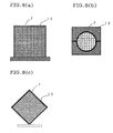
- Fig. 1 is a schematic perspective view showing an embodiment of the honeycomb formed body of the present invention.
- Fig. 2 is a schematic perspective view showing another embodiment of the honeycomb formed body of the present invention.
- Fig. 3 is a schematic perspective view showing a honeycomb formed body of the present invention placed on a mounting jig.
- Fig. 4 is a schematic perspective view showing a honeycomb formed body of the present invention covered with a guide.
- Fig. 5 is a schematic perspective view showing a honeycomb formed body of the present invention covered with another type of the guide.
- Fig. 6 is a schematic front view showing a honeycomb formed body of the present invention placed on another type of the mounting jig.
- Fig. 7 is a schematic perspective view showing a honeycomb formed body of the present invention covered with still another type of the guide.
- Fig. 8(a), Fig. 8(b) and Fig. 8(c) are schematic front views showing a honeycomb formed body of the present invention covered with still another type of the guide respectively.
- Fig. 9 is a schematic perspective view showing a honeycomb formed body of the present invention covered with still another type of the guide.
- Fig. 10 is a schematic side view showing a method for measuring distortion of a honeycomb formed body of the present invention.
- section means a section perpendicular to the axial direction shown in Fig. 1, unless otherwise specified.
- the honeycomb formed body according to the first aspect and the second aspect comprises an outer wall 7, partition walls 2 disposed inside the outer wall 7 and a plurality of cells 3 surrounded by the partition walls 2 and extending in an axial direction of the honeycomb formed body.
- a significant feature of the first aspect is provision of the drying step which, in drying such a honeycomb formed body, starts drying in a state where at least a part of the outer walls 7a and 7b is covered with a guide 12 covering the outer wall so as not to come into contact with the outer wall, for example the outer wall 7a and/or 7b as shown in Fig. 3 and Fig. 4, namely in a state where the guide covers the outer wall at a certain distance.
- the distance between the outer wall and the guide, or a distance a between the outer wall 7a and the guide 12 as shown, for example, in Fig. 4 is too large, the effect of preventing distortion is difficult to be achieved, so that such distance is not preferable. Therefore, the distance a is preferably 1.0 mm or less. On the other hand, if the distance a is too small, the effect of preventing cross sectional deformation of the honeycomb formed body is difficult to be achieved, so that such distance is not preferable. Therefore, the distance a is preferably 0.1 mm or more. Likewise, the distance between the outer wall 7b located on the lateral side and the guide is preferably in the range of 0.1 mm and 1.0 mm.
- the maximum pressure at the time the honeycomb formed body and the guide come into contact with each other during the drying step is desirably set to less than 0.2 MPa, preferably 0.05 MPa or less in order to prevent the sectional shape from deforming to some extent.
- Fig. 5 shows another embodiment of the first aspect.
- Fig. 5 shows a preferred example when a honeycomb formed body of cylindrical shape is subjected to drying.
- the honeycomb formed body is placed on a mounting jig 10 having a recess of semi-cylindrical shape, and then the outer wall 7 is covered with a guide 12 having a recess portion of semi-cylindrical shape with a radius slightly larger than the sectional radius of the honeycomb formed body.
- a part of the outer wall 7, namely, the outer wall located on the upper side does not come into contact with the guide 12.
- a honeycomb formed body 1 of rectangular prism is received by a mounting jig 10 having a V-shaped cross section, to 8(c), for example, wherein the pressure applied by the guide 12 on the outer wall 7 at the contact portion is less than 0.2 MPa, preferably 0.05 MPa or less in the drying step.
- the drying is conducted in a state where the guide and the outer wall are in contact with each other and that a generally-used pressure, such as pressures of 0.2 MPa or more is applied on the outer wall by the guide, the sectional shape of the honeycomb formed body deforms although distortion is prevented.
- a generally-used pressure such as pressures of 0.2 MPa or more
- the pressure applied during the drying less than 0.2 MPa, preferably 0.05 MPa or less, it is possible to prevent the sectional shape from deforming to some extent, while preventing the distortion.
- all the surface that the guide covers is not necessarily in contact with the outer wall, and in the embodiment as shown in Fig. 8(a), for example, when the outer wall located on the upper side is in contact with the guide, the outer wall located on the lateral side may not be in contact with the guide 12.
- the distance is preferably in the range of 0.1 to 1.0 mm.
- the way of applying pressure is not particularly limited, and examples of the pressure application method include applying a load downward from above the guide, applying pressure by guide's own weight, and applying pressure from lateral side by pressure applying means in the embodiment as shown in Fig. 8(a).
- the outer wall 7 using a guide 12 having an and the outer wall 7a on the upper side of the honeycomb formed body is covered with a guide 12 having a V-shaped cross section which is formed by sides each being slightly larger than one side of the rectangular cross section of the honeycomb formed body 1.
- the mounting jig is not an essential element, and the embodiment shown in Fig. 3 may lack the mounting jig, for example.
- the mounting jig and the guide may be integrally formed. In such a case, the outer wall on the lower side of the honeycomb formed body comes into contact with the lower part of the guide because the honeycomb formed body is placed in the integrated guide, however, the effect of the present invention can be achieved because the part being in no contact is positioned upside.
- the honeycomb formed body according to the second aspect is similar to that of the first aspect.
- a significant feature of the second aspect is the drying step which starts drying in a state where at least a part of outer wall of the honeycomb formed body is covered with a guide 12 in such a manner that the guide is in contact with at least a part of outer wall 7, as shown in Figs. 8(a) to 8(c), for example, wherein the pressure applied by the guide 12 on the outer wall 7 at the contact portion is less than 0.2 MPa, preferably 0.05 MPa or less in the drying step.
- the drying is conducted in a state where the guide and the outer wall are in contact with each other and that a generally-used pressure, such as pressures of 0.2 MPa or more is applied on the outer wall by the guide, the sectional shape of the honeycomb formed body deforms although distortion is prevented.
- a generally-used pressure such as pressures of 0.2 MPa or more
- the pressure applied during the drying less than 0.2 MPa, preferably 0.05 MPa or less, it is possible to prevent the sectional shape from deforming to some extent, while preventing the distortion.
- all the surface that the guide covers is not necessarily in contact with the outer wall, and in the embodiment as shown in Fig. 8(a), for example, when the outer wall located on the upper side is in contact with the guide, the outer wall located on the lateral side may not be in contact with the guide 12.
- the distance is preferably in the range of 0.1 to 1.0 mm.
- the way of applying pressure is not particularly limited, and examples of the pressure application method include applying a load downward from above the guide, applying pressure by guide's own weight, and applying pressure from lateral side by pressure applying means in the embodiment as shown in Fig. 8(a).
- the outer wall 7 it is also preferred to cover the outer wall 7 using a guide 12 having an opening 13 as shown in Fig. 9, for example.
- a guide 12 having an opening 13 As shown in Fig. 9, for example, it is possible to improve the evaporation efficiency of moisture of the honeycomb formed body and improve the drying efficiency.
- the shape and the position of the opening are not particularly limited.
- the opening of larger size is desired from the view point of the drying efficiency.
- the opening area of the opening is preferably 80% or less, more preferably 70% or less and still preferably 60% or less, relative to the area of the guide including the opening.
- the extent of the outer wall covered with the guide is preferably in the range of 20 to 100%, more preferably in the range of 30 to 100%, and still preferably in the range of 40 to 100%, relative to the surface area of the entire surface of the outer wall.
- the extent is preferably in the range of 20 to 90%, more preferably in the range of 30 to 80%, and still preferably in the range of 40 to 70%. Therefore, in the case of providing an opening, it is preferred to provide the opening so as to satisfy the above ranges.
- the expression "extent of the outer wall covered with the guide” means the extent excluding the opening if exists.
- the drying means in the first or second aspect of the invention is not particularly limited, however, microwave drying and/or hot air drying is preferably used.
- the microwave drying has an advantage of executing rapid drying, however, the drying cannot be completed by the microwave drying in some cases. Therefore, it is preferred to combine the microwave drying and the hot air drying. Also preferred is conducting the hot air drying after removing moisture to some extent by conducting the microwave drying.
- the drying is started in a state where at least a part of the outer wall is covered with the guide according to the first aspect or the second aspect of the present invention in either the microwave drying step or the hot air drying step. It is more preferred that the guide is used in the microwave drying step. It is especially preferred that the drying is started in a state where at least a part of the outer wall is covered with the guide in both of the drying steps.
- the output of microwave in the microwave drying step is not particularly limited, however it is preferably in the range of about 0.5 to 3 kW/kg. If the output of microwave is too low, longer drying time is required to possibly cause collapse by the own weight. On the other hand, if the output of microwave is too high, a problem may occur that the binder starts burning. From the view point of preventing occurrence of distortion, it is also preferred that 30 to 80% by mass of the total dewatering amount, preferably 30 to 60% by mass of the total dewatering amount is dewatered in the microwave drying step, and the remaining moisture is dewatered in the hot air drying step. Also, it is preferred to use ventilating type or hot air circulating type hot air drying means.
- the honeycomb formed body according to the first or second aspect preferably contains ceramics as a main component in the case of using the honeycomb formed body as various kinds of filters and carries. It is especially preferred that the main component contains silicon carbide from the view point of heat resistance or the like in the case where the honeycomb formed body is used as DPF or the like.
- a mixed powder containing 80% by mass of SiC powder and 20% by mass of metal Si powder was prepared.
- methyl cellulose, hydroxypropoxyl methyl cellulose, surfactant, and water were added to prepare kneaded clay having plasticity.
- This kneaded clay was extruded to form a honeycomb formed body A of rectangular prism as shown in Fig. 1 having a sectional shape of square 40 mm on a side and a length of 400 mm, and a honeycomb formed body B of cylindrical shape as shown in Fig. 2 having a diameter of 50 mm and a length of 400 mm.
- the honeycomb formed body B was set into the mounting jig and the guide as shown in Fig. 8(b) having no space with the outer wall of the honeycomb formed body B. That is, the outer wall of the honeycomb formed body B was covered with the mounting jig and the guide that covers the outer wall such that the outer wall and the guide come into direct contact. After applying pressure on the honeycomb formed body B by applying a load downward from above the guide at pressures listed in Table 1, microwave drying was conducted, followed by hot air drying to the complete dried state. Then, the honeycomb formed body was taken out and a difference between the maximum diameter and the minimum diameter of the end face was measured for checking deformation of the sectional shape, and the resultant values are shown in Table 1 as a tolerance of product profile.
- Example 2 Using the honeycomb formed body A, the test similar to Example 1 was conducted except that the mounting jig and the guide as shown in Fig. 8(a) were used in Example 2 and the mounting jig and the guide as shown in Fig. 8(c) were used in Example 3. The results are shown in Table 1
- the drying was conducted in the drying condition similar to that of Example 1 while using the mounting jig and the guide as shown in Fig. 5 and changing the space a between the guide and the outer wall from 0.2 to 3.0 mm as shown in Table 3.
- the distortion amount ⁇ of each honeycomb formed body was measured.
- the distortion amount ⁇ was determined using a dial gauge by placing the honeycomb formed body on a specific jig, and measuring the difference between the average of vertical positions at two points x1 and x2 located at ends of the longitudinal direction and the vertical position of the outer wall in the mid point of these two points.
- Table 2 At a distance a in the range of 0.2 to 1.0 mm, the distortion amount was small and allowable, however, at a distance a of 1.5 mm or more, the distortion amount was large and exceeded the allowable range.
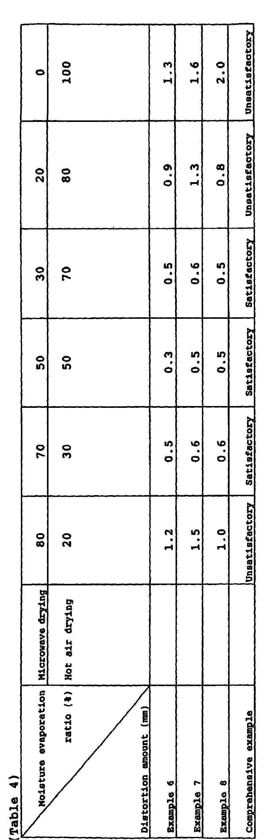
- the honeycomb formed body A was placed on the mounting jig 10 and covered with the guide 12 having the opening 13 as shown in Fig. 9 so that the guide was disposed at a distance of 0.5 mm from the outer wall.
- the opening area of the opening 13 was varied at 60%, 30% and 0% (i.e. no opening) relative to the area of the guide including the opening 13, and a sample not covered with the guide was also prepared. These samples were subjected to microwave drying for 160 seconds at an output of 2.0 kW/kg, followed by hot air drying at 120° C for 20 minutes. From the relation between the drying time and the moisture evaporation ratio, a relative moisture evaporation rate was determined relative to the moisture evaporation rate obtained by the sample not having the guide. The distortion amount of the honeycomb formed body was also determined. The results shown in Table 4 demonstrate that the distortion amount is reduced by the guide, and the moisture evaporation rate is increased by providing an opening in the guide and reducing the area of the guide covering the outer wall.
- the present invention can be advantageously used for drying a honeycomb formed body.
Landscapes
- Engineering & Computer Science (AREA)
- Chemical & Material Sciences (AREA)
- Ceramic Engineering (AREA)
- Structural Engineering (AREA)
- Manufacturing & Machinery (AREA)
- Mechanical Engineering (AREA)
- Materials Engineering (AREA)
- Organic Chemistry (AREA)
- Inorganic Chemistry (AREA)
- Thermal Sciences (AREA)
- Physics & Mathematics (AREA)
- General Engineering & Computer Science (AREA)
- Devices For Post-Treatments, Processing, Supply, Discharge, And Other Processes (AREA)
- Drying Of Solid Materials (AREA)
Abstract
Description
- The present invention relates to a method of drying a honeycomb formed body. Particularly, the present invention relates to a method of drying a honeycomb formed body in which distortion or cross sectional deformation of a honeycomb formed body can be reduced.
- A honeycomb structure is widely used for catalyst carriers and various filters. Recently, The honeycomb structure gets attention as a filter for trapping particulate matter exhausted from diesel engine (hereinafter referred to as DPF).
- Such a honeycomb structure generally contains ceramics as a main component in many cases. Following method is generally taken for producing the honeycomb structure. After adding water and several kinds of additives to the ceramic raw material to form kneaded clay, the kneaded clay is extruded to form honeycomb formed body, then the formed body is dried and fired to obtain the honeycomb structure.
- Such a drying process in the production method is faced with the problem that deformation such as distortion or twist occurs in the honeycomb formed body. Sometimes the honeycomb formed body is formed by joining a plurality of segments having honeycomb structure into an integral body. This approach is also faced with the problem that any deformation such as distortion or twisting occurring in any segment may complicate the joining process.
- As a method for inhibiting distortion and the like in drying, there is a method for drying a ceramic formed body having a honeycomb structure by using a drying jig having an upper jig and a lower jig equipped with pressure applying means, the applied pressure being preferably 0.4 to 0.6 MPa as disclosed in Japanese Patent Application Laid-open No. 2001-130973. There is a drying jig having two separate jigs formed in such a way that they enclose in a closely contacted state nearly the whole surface of sides parallel to a longitudinal direction of a ceramic formed body having a honeycomb structure as disclosed in Japanese Patent Application Laid-open No. 2001-19533. In these methods, though the distortion of the formed body can be inhibited, cells may be collapsed in some cases, which may result in cross sectional deformation of the formed body.
- The present invention has been made in view of such a situation and aims to provide a method of drying a honeycomb formed body in which distortion or cross sectional deformation of a honeycomb formed body can be reduced.
- The present invention provides first a method of drying a honeycomb formed body comprising an outer wall, partition walls disposed inside the outer wall, and cells surrounded by the partition walls and extending in an axial direction of the honeycomb formed body, wherein the method comprises a drying step of starting to dry in a state of covering at least a part of the outer wall with a guide covering the outer wall so as not to come into contact with the outer wall (a first aspect of the invention).
- In the first aspect of the invention, the drying step preferably starts with a distance between the outer wall and the guide covering the outer wall of 0.1 to 1. 0 mm. Furthermore, in the case where the outer wall and the guide come into contact with each other during the drying step that starts with a distance between the outer wall and the guide covering the outer wall of 0.1 mm or less, the pressure applied to the outer wall from the guide is preferably less than 0.2 MPa.
- Secondly, the present invention provides a method of drying a honeycomb formed body comprising an outer wall, partition walls disposed inside the outer wall and a plurality of cells surrounded by the partition walls and extending in an axial direction of the honeycomb formed body, and the method comprises comprising the step of drying the honeycomb formed body in a state where at least a part of the outer wall is covered with a guide that covers the outer wall while being in contact with the outer wall, wherein in the drying step the pressure applied to the outer wall from the guide at the point of contact is less than 0.2 MPa (a second aspect of the invention).
- In the first or second aspect of the invention, it is preferred that the guide has an opening, and the extent that the guide covers the outer wall is in the range of 20 to 100%, relative to the surface area of the entire outer wall face. It is also preferred that the drying step includes a microwave drying step and a hot air drying step, and the hot air drying step is conducted after the microwave drying step. In this case, the drying preferably starts in a state where at least a part of the outer wall is covered with the guide at least in the hot air drying step, and also the drying preferably starts in a state where at least a part of the outer wall is covered with the guide at least in the microwave drying step. Additionally, in the microwave drying step, output of microwave per unit mass of the honeycomb formed body is preferably in the range of 0.5 to 3 kW/kg, and dewatering ratio relative to the total dewatering amount in the complete drying step is preferably in the range of 30 to 80% by mass. It is also preferred that the honeycomb formed body contains ceramics as a main component and the main component contains silicon carbide.
- Fig. 1 is a schematic perspective view showing an embodiment of the honeycomb formed body of the present invention.
- Fig. 2 is a schematic perspective view showing another embodiment of the honeycomb formed body of the present invention.
- Fig. 3 is a schematic perspective view showing a honeycomb formed body of the present invention placed on a mounting jig.
- Fig. 4 is a schematic perspective view showing a honeycomb formed body of the present invention covered with a guide.
- Fig. 5 is a schematic perspective view showing a honeycomb formed body of the present invention covered with another type of the guide.
- Fig. 6 is a schematic front view showing a honeycomb formed body of the present invention placed on another type of the mounting jig.
- Fig. 7 is a schematic perspective view showing a honeycomb formed body of the present invention covered with still another type of the guide.
- Fig. 8(a), Fig. 8(b) and Fig. 8(c) are schematic front views showing a honeycomb formed body of the present invention covered with still another type of the guide respectively.
- Fig. 9 is a schematic perspective view showing a honeycomb formed body of the present invention covered with still another type of the guide.
- Fig. 10 is a schematic side view showing a method for measuring distortion of a honeycomb formed body of the present invention.
- Methods of drying a honeycomb formed body according to the first and the second aspects of the present invention are described below in detail with reference to the concrete embodiments. However, the present invention is not restricted to the following embodiments. Incidentally, in the present description, the expression "section" means a section perpendicular to the axial direction shown in Fig. 1, unless otherwise specified.
- As shown in Fig. 1 or Fig. 2, for example, the honeycomb formed body according to the first aspect and the second aspect comprises an
outer wall 7,partition walls 2 disposed inside theouter wall 7 and a plurality ofcells 3 surrounded by thepartition walls 2 and extending in an axial direction of the honeycomb formed body. A significant feature of the first aspect is provision of the drying step which, in drying such a honeycomb formed body, starts drying in a state where at least a part of the outer walls 7a and 7b is covered with aguide 12 covering the outer wall so as not to come into contact with the outer wall, for example the outer wall 7a and/or 7b as shown in Fig. 3 and Fig. 4, namely in a state where the guide covers the outer wall at a certain distance. - By starting the drying step in such a state, it is possible to dry the honeycomb formed body while preventing it from being distorted without applying an excessive pressure. Therefore, it is possible to prevent occurrence of both the cross sectional deformation and the distortion of the honeycomb formed body.
- In the first aspect, if the distance between the outer wall and the guide, or a distance a between the outer wall 7a and the
guide 12 as shown, for example, in Fig. 4 is too large, the effect of preventing distortion is difficult to be achieved, so that such distance is not preferable. Therefore, the distance a is preferably 1.0 mm or less. On the other hand, if the distance a is too small, the effect of preventing cross sectional deformation of the honeycomb formed body is difficult to be achieved, so that such distance is not preferable. Therefore, the distance a is preferably 0.1 mm or more. Likewise, the distance between the outer wall 7b located on the lateral side and the guide is preferably in the range of 0.1 mm and 1.0 mm. - If these distances are 0.1 mm or less, the maximum pressure at the time the honeycomb formed body and the guide come into contact with each other during the drying step is desirably set to less than 0.2 MPa, preferably 0.05 MPa or less in order to prevent the sectional shape from deforming to some extent.
- Fig. 5 shows another embodiment of the first aspect. Fig. 5 shows a preferred example when a honeycomb formed body of cylindrical shape is subjected to drying. The honeycomb formed body is placed on a
mounting jig 10 having a recess of semi-cylindrical shape, and then theouter wall 7 is covered with aguide 12 having a recess portion of semi-cylindrical shape with a radius slightly larger than the sectional radius of the honeycomb formed body. In this manner, it is possible to cover the outer wall so that a part of theouter wall 7, namely, the outer wall located on the upper side does not come into contact with theguide 12. - Still another embodiment is shown in Fig. 6 and Fig. 7. In this case, a honeycomb formed
body 1 of rectangular prism is received by amounting jig 10 having a V-shaped cross section, to 8(c), for example, wherein the pressure applied by theguide 12 on theouter wall 7 at the contact portion is less than 0.2 MPa, preferably 0.05 MPa or less in the drying step. - If the drying is conducted in a state where the guide and the outer wall are in contact with each other and that a generally-used pressure, such as pressures of 0.2 MPa or more is applied on the outer wall by the guide, the sectional shape of the honeycomb formed body deforms although distortion is prevented. However, by setting the pressure applied during the drying less than 0.2 MPa, preferably 0.05 MPa or less, it is possible to prevent the sectional shape from deforming to some extent, while preventing the distortion.
- In the second aspect, all the surface that the guide covers is not necessarily in contact with the outer wall, and in the embodiment as shown in Fig. 8(a), for example, when the outer wall located on the upper side is in contact with the guide, the outer wall located on the lateral side may not be in contact with the
guide 12. In this case, the distance is preferably in the range of 0.1 to 1.0 mm. - In the second aspect, the way of applying pressure is not particularly limited, and examples of the pressure application method include applying a load downward from above the guide, applying pressure by guide's own weight, and applying pressure from lateral side by pressure applying means in the embodiment as shown in Fig. 8(a).
- In the first or second aspect of the invention, it is also preferred to cover the
outer wall 7 using aguide 12 having an and the outer wall 7a on the upper side of the honeycomb formed body is covered with aguide 12 having a V-shaped cross section which is formed by sides each being slightly larger than one side of the rectangular cross section of the honeycomb formedbody 1. At this time, since the load of theguide 12 is received at or in the vicinity of an end face 14 of the mounting jig, theguide 12 and the upper outer wall 7a will not come into contact with each other. - In the above embodiments, although the honeycomb formed body is surrounded by the combination of the mounting jig and the guide, the mounting jig is not an essential element, and the embodiment shown in Fig. 3 may lack the mounting jig, for example. In the embodiment shown in Fig. 5 or Fig. 7, the mounting jig and the guide may be integrally formed. In such a case, the outer wall on the lower side of the honeycomb formed body comes into contact with the lower part of the guide because the honeycomb formed body is placed in the integrated guide, however, the effect of the present invention can be achieved because the part being in no contact is positioned upside.
- Next, a preferred specific example in the second aspect of the present invention will be explained. The honeycomb formed body according to the second aspect is similar to that of the first aspect. A significant feature of the second aspect is the drying step which starts drying in a state where at least a part of outer wall of the honeycomb formed body is covered with a
guide 12 in such a manner that the guide is in contact with at least a part ofouter wall 7, as shown in Figs. 8(a) to 8(c), for example, wherein the pressure applied by theguide 12 on theouter wall 7 at the contact portion is less than 0.2 MPa, preferably 0.05 MPa or less in the drying step. - If the drying is conducted in a state where the guide and the outer wall are in contact with each other and that a generally-used pressure, such as pressures of 0.2 MPa or more is applied on the outer wall by the guide, the sectional shape of the honeycomb formed body deforms although distortion is prevented. However, by setting the pressure applied during the drying less than 0.2 MPa, preferably 0.05 MPa or less, it is possible to prevent the sectional shape from deforming to some extent, while preventing the distortion.
- In the second aspect, all the surface that the guide covers is not necessarily in contact with the outer wall, and in the embodiment as shown in Fig. 8(a), for example, when the outer wall located on the upper side is in contact with the guide, the outer wall located on the lateral side may not be in contact with the
guide 12. In this case, the distance is preferably in the range of 0.1 to 1.0 mm. - In the second aspect, the way of applying pressure is not particularly limited, and examples of the pressure application method include applying a load downward from above the guide, applying pressure by guide's own weight, and applying pressure from lateral side by pressure applying means in the embodiment as shown in Fig. 8(a).
- In the first or second aspect of the invention, it is also preferred to cover the
outer wall 7 using aguide 12 having an opening 13 as shown in Fig. 9, for example. By employing such a configuration, it is possible to improve the evaporation efficiency of moisture of the honeycomb formed body and improve the drying efficiency. In this case, the shape and the position of the opening are not particularly limited. Preferably, the opening of larger size is desired from the view point of the drying efficiency. However, if the opening is too large, the extent of the outer wall covered with the guide becomes too small to make the present invention difficult to give the effect. Therefore, the opening area of the opening is preferably 80% or less, more preferably 70% or less and still preferably 60% or less, relative to the area of the guide including the opening. - Likewise, from the view point of suppressing the distortion, the extent of the outer wall covered with the guide is preferably in the range of 20 to 100%, more preferably in the range of 30 to 100%, and still preferably in the range of 40 to 100%, relative to the surface area of the entire surface of the outer wall. From the view point of realizing suppression of distortion and improvement of drying efficiency, the extent is preferably in the range of 20 to 90%, more preferably in the range of 30 to 80%, and still preferably in the range of 40 to 70%. Therefore, in the case of providing an opening, it is preferred to provide the opening so as to satisfy the above ranges. Herein the expression "extent of the outer wall covered with the guide" means the extent excluding the opening if exists.
- The drying means in the first or second aspect of the invention is not particularly limited, however, microwave drying and/or hot air drying is preferably used. The microwave drying has an advantage of executing rapid drying, however, the drying cannot be completed by the microwave drying in some cases. Therefore, it is preferred to combine the microwave drying and the hot air drying. Also preferred is conducting the hot air drying after removing moisture to some extent by conducting the microwave drying.
- In the case where the hot air drying is conducted after the microwave drying, it is preferred that the drying is started in a state where at least a part of the outer wall is covered with the guide according to the first aspect or the second aspect of the present invention in either the microwave drying step or the hot air drying step. It is more preferred that the guide is used in the microwave drying step. It is especially preferred that the drying is started in a state where at least a part of the outer wall is covered with the guide in both of the drying steps.
- The output of microwave in the microwave drying step is not particularly limited, however it is preferably in the range of about 0.5 to 3 kW/kg. If the output of microwave is too low, longer drying time is required to possibly cause collapse by the own weight. On the other hand, if the output of microwave is too high, a problem may occur that the binder starts burning. From the view point of preventing occurrence of distortion, it is also preferred that 30 to 80% by mass of the total dewatering amount, preferably 30 to 60% by mass of the total dewatering amount is dewatered in the microwave drying step, and the remaining moisture is dewatered in the hot air drying step. Also, it is preferred to use ventilating type or hot air circulating type hot air drying means.
- The honeycomb formed body according to the first or second aspect preferably contains ceramics as a main component in the case of using the honeycomb formed body as various kinds of filters and carries. It is especially preferred that the main component contains silicon carbide from the view point of heat resistance or the like in the case where the honeycomb formed body is used as DPF or the like.
- The present invention will concretely be described hereinafter in terms of examples. However the present invention is not limited to these examples.
- As a raw material, a mixed powder containing 80% by mass of SiC powder and 20% by mass of metal Si powder was prepared. To the powder, methyl cellulose, hydroxypropoxyl methyl cellulose, surfactant, and water were added to prepare kneaded clay having plasticity. This kneaded clay was extruded to form a honeycomb formed body A of rectangular prism as shown in Fig. 1 having a sectional shape of square 40 mm on a side and a length of 400 mm, and a honeycomb formed body B of cylindrical shape as shown in Fig. 2 having a diameter of 50 mm and a length of 400 mm.
- The honeycomb formed body B was set into the mounting jig and the guide as shown in Fig. 8(b) having no space with the outer wall of the honeycomb formed body B. That is, the outer wall of the honeycomb formed body B was covered with the mounting jig and the guide that covers the outer wall such that the outer wall and the guide come into direct contact. After applying pressure on the honeycomb formed body B by applying a load downward from above the guide at pressures listed in Table 1, microwave drying was conducted, followed by hot air drying to the complete dried state. Then, the honeycomb formed body was taken out and a difference between the maximum diameter and the minimum diameter of the end face was measured for checking deformation of the sectional shape, and the resultant values are shown in Table 1 as a tolerance of product profile.
- Using the honeycomb formed body A, the test similar to Example 1 was conducted except that the mounting jig and the guide as shown in Fig. 8(a) were used in Example 2 and the mounting jig and the guide as shown in Fig. 8(c) were used in Example 3. The results are shown in Table 1

- Reviewing the results of Examples 1 to 3 in Table 1 comprehensively, the honeycomb formed body collapsed and the sectional shape was largely deformed near the part where the outer wall was in contact with the guide when the applied pressure was 0.2 MPa or more. On the other hand, when the applied pressure was 0.05 MPa or less, the deformation was not so significant.
- Using the honeycomb formed body B, the drying was conducted in the drying condition similar to that of Example 1 while using the mounting jig and the guide as shown in Fig. 5 and changing the space a between the guide and the outer wall from 0.2 to 3.0 mm as shown in Table 3. Then, the distortion amount β of each honeycomb formed body was measured. As shown in Fig. 10, the distortion amount β was determined using a dial gauge by placing the honeycomb formed body on a specific jig, and measuring the difference between the average of vertical positions at two points x1 and x2 located at ends of the longitudinal direction and the vertical position of the outer wall in the mid point of these two points. The results are shown in Table 2. At a distance a in the range of 0.2 to 1.0 mm, the distortion amount was small and allowable, however, at a distance a of 1.5 mm or more, the distortion amount was large and exceeded the allowable range.

- The honeycomb formed body A was placed on the mounting
jig 10 and covered with theguide 12 having the opening 13 as shown in Fig. 9 so that the guide was disposed at a distance of 0.5 mm from the outer wall. The opening area of the opening 13 was varied at 60%, 30% and 0% (i.e. no opening) relative to the area of the guide including the opening 13, and a sample not covered with the guide was also prepared. These samples were subjected to microwave drying for 160 seconds at an output of 2.0 kW/kg, followed by hot air drying at 120° C for 20 minutes. From the relation between the drying time and the moisture evaporation ratio, a relative moisture evaporation rate was determined relative to the moisture evaporation rate obtained by the sample not having the guide. The distortion amount of the honeycomb formed body was also determined. The results shown in Table 4 demonstrate that the distortion amount is reduced by the guide, and the moisture evaporation rate is increased by providing an opening in the guide and reducing the area of the guide covering the outer wall.
- As described above, by using the drying method of the honeycomb formed body according to the first or second aspect of the invention, it was possible to avoid both distortion and cross sectional deformation during the drying. Therefore, the present invention can be advantageously used for drying a honeycomb formed body.
Claims (13)
- A method of drying a honeycomb formed body comprising an outer wall, partition walls disposed inside the outer wall, and a plurality of cells surrounded by the partition walls and extending in an axial direction of the honeycomb formed body,
characterized in that the method comprises a drying step starting in a state of covering at least a part of the outer wall with a guide covering the outer wall so as not to come into contact with the outer wall. - The method of drying a honeycomb formed body according to claim 1, wherein the drying step starts with a distance between the outer wall and the guide covering the outer wall of 0.1 to 1.0 mm.
- The method of drying a honeycomb formed body according to claim 1, wherein in the case where the outer wall and the guide come into contact with each other during the drying step that starts with a distance between the outer wall and the guide covering the outer wall of 0.1 mm or less, the pressure applied to the outer wall from the guide is less than 0.2 MPa.
- A method of drying a honeycomb formed body comprising an outer wall, partition walls disposed inside the outer wall, and cells surrounded by the partition walls and extending in an axial direction of the honeycomb formed body,
characterized in that the method comprises a drying step drying in a state of covering at least a part of the outer wall with a guide covering the outer wall so as to come into contact with the outer wall,
pressure from the guide to the outer wall being less than 0.2 MPa at a part where the guide comes into contact with the outer wall in the drying step. - The method of drying a honeycomb formed body according to any of claims 1 to 4, wherein the guide has an opening.
- The method of drying a honeycomb formed body according to any one of claims 1 to 5, wherein the extent that the guide covers the outer wall is in the range of 20 to 100% relative to the surface area of the entire outer wall.
- The method of drying a honeycomb formed body according to any one of claims 1 to 6, wherein the drying includes a microwave drying step and a hot air drying step, and the hot air drying step is conducted after the microwave drying step.
- The method of drying a honeycomb formed body according to claim 7, wherein at least in the hot air drying step, drying is started in a state where at least a part of the outer wall is covered with the guide.
- The method of drying a honeycomb formed body according to claim 7 or 8, wherein at least in the microwave drying step, drying is started in a state where at least a part of the outer wall is covered with the guide.
- The method of drying a honeycomb formed body according to any one of claims 7 to 9, wherein in the microwave drying step, microwave output per unit mass of the honeycomb formed body is in the range of 0.5 to 3 kW/kg.
- The method of drying a honeycomb formed body according to any one of claims 7 to 10, wherein dewatering ratio in the microwave drying step is 30 to 80% by mass, relative to the total dewatering amount in the complete drying step.
- The method of drying a honeycomb formed body according to any of claims 1 to 11, wherein the honeycomb formed body contains ceramics as a main component.
- The method of drying a honeycomb formed body according to claim 12, wherein the main component contains silicon carbide.
Applications Claiming Priority (3)
| Application Number | Priority Date | Filing Date | Title |
|---|---|---|---|
| JP2002091575A JP2003285312A (en) | 2002-03-28 | 2002-03-28 | Method for drying honeycomb formed body |
| JP2002091575 | 2002-03-28 | ||
| PCT/JP2003/001159 WO2003082540A1 (en) | 2002-03-28 | 2003-02-05 | Method of drying honeycomb formed body |
Publications (3)
| Publication Number | Publication Date |
|---|---|
| EP1491307A1 true EP1491307A1 (en) | 2004-12-29 |
| EP1491307A4 EP1491307A4 (en) | 2007-01-10 |
| EP1491307B1 EP1491307B1 (en) | 2010-06-09 |
Family
ID=28671684
Family Applications (1)
| Application Number | Title | Priority Date | Filing Date |
|---|---|---|---|
| EP03705048A Expired - Lifetime EP1491307B1 (en) | 2002-03-28 | 2003-02-05 | Method of drying honeycomb formed body |
Country Status (8)
| Country | Link |
|---|---|
| US (2) | US20050115101A1 (en) |
| EP (1) | EP1491307B1 (en) |
| JP (1) | JP2003285312A (en) |
| KR (1) | KR100613680B1 (en) |
| AU (1) | AU2003211917A1 (en) |
| DE (1) | DE60332926D1 (en) |
| PL (1) | PL202605B1 (en) |
| WO (1) | WO2003082540A1 (en) |
Cited By (6)
| Publication number | Priority date | Publication date | Assignee | Title |
|---|---|---|---|---|
| EP1826517A1 (en) * | 2006-02-28 | 2007-08-29 | Ibiden Co., Ltd. | Drying jig, drying method of honeycomb molded body, and manufacturing method of honeycomb structured body |
| US20080023886A1 (en) * | 2006-07-28 | 2008-01-31 | Paul Andreas Adrian | Microwave drying of ceramic structures |
| WO2008121263A1 (en) * | 2007-03-30 | 2008-10-09 | Corning Incorporated | Method and applicator for selective electromagnetic drying of ceramic-forming mixture |
| BE1018418A3 (en) * | 2004-08-27 | 2010-11-09 | Ngk Insulators Ltd | METHOD FOR MICROWAVE DRYING OF ALVEOLED MOLDED BODIES |
| WO2013181058A3 (en) * | 2012-05-29 | 2014-03-27 | Corning Incorporated | Microwave drying of ceramic honeycomb logs using a customizable cover |
| CN107226701A (en) * | 2016-03-24 | 2017-10-03 | 日本碍子株式会社 | The manufacture method of honeycomb structured body |
Families Citing this family (15)
| Publication number | Priority date | Publication date | Assignee | Title |
|---|---|---|---|---|
| JP4527963B2 (en) * | 2003-11-04 | 2010-08-18 | 日本碍子株式会社 | Microwave drying method |
| KR101076121B1 (en) * | 2004-09-22 | 2011-10-21 | 에스케이이노베이션 주식회사 | Method for drying honeycomb type ceramics |
| EP2147905B1 (en) * | 2007-05-16 | 2015-06-17 | NGK Insulators, Ltd. | Method for producing bonded body of honeycomb segments |
| KR101367945B1 (en) * | 2007-05-28 | 2014-02-27 | 주식회사 칸세라 | Drying jig and drying method for extruded product of sic honeycomb segment |
| EP2539656B1 (en) | 2010-02-25 | 2015-07-29 | Corning Incorporated | Tray assemblies and methods for manufacturing ceramic articles |
| JP5832312B2 (en) * | 2012-01-16 | 2015-12-16 | 三菱重工業株式会社 | Method for drying honeycomb structure |
| JP5832337B2 (en) * | 2012-02-24 | 2015-12-16 | 三菱重工業株式会社 | Method for drying honeycomb structure |
| JP5766631B2 (en) * | 2012-02-24 | 2015-08-19 | 三菱重工業株式会社 | Method for drying honeycomb structure |
| US10173933B2 (en) | 2013-05-06 | 2019-01-08 | Corning Incorporated | Rapid drying of ceramic greenwares |
| CN106827206A (en) * | 2017-03-22 | 2017-06-13 | 河南鑫海电力设备有限公司 | A kind of insulator mud section dries end liner |
| JP7016267B2 (en) * | 2017-03-24 | 2022-02-04 | 日本碍子株式会社 | Method of drying columnar honeycomb molded body and method of manufacturing columnar honeycomb structure |
| US11168033B2 (en) | 2017-03-24 | 2021-11-09 | Ngk Insulators, Ltd. | Method for drying columnar honeycomb formed body and method for producing columnar honeycomb structure |
| JP7016721B2 (en) * | 2018-02-19 | 2022-02-07 | 株式会社ミツトヨ | Dial gauge |
| JP6773701B2 (en) * | 2018-03-02 | 2020-10-21 | 日本碍子株式会社 | Jig for drying a square columnar honeycomb molded body, a drying method, and a method for manufacturing a square columnar honeycomb fired product. |
| JP2022126503A (en) | 2021-02-18 | 2022-08-30 | 日本碍子株式会社 | Method for producing honeycomb structure and method for producing electric heating type carrier |
Family Cites Families (18)
| Publication number | Priority date | Publication date | Assignee | Title |
|---|---|---|---|---|
| JPS61205673A (en) * | 1985-03-07 | 1986-09-11 | 富士電機株式会社 | Method of dewaxing and burning ceramic formed body |
| JPS6374970A (en) * | 1986-09-17 | 1988-04-05 | 株式会社豊田中央研究所 | Method of dewaxing ceramic formed body |
| JPH0379305A (en) * | 1989-08-21 | 1991-04-04 | Sekisui Chem Co Ltd | Manufacture of hydraulic inorganic molding |
| JPH03122058A (en) * | 1989-10-02 | 1991-05-24 | Seibu Giken:Kk | Drying of honeycomb-like molded article |
| JPH0645131B2 (en) * | 1990-03-28 | 1994-06-15 | 日本碍子株式会社 | Jig for drying long ceramic moldings |
| JPH0421572A (en) * | 1990-05-14 | 1992-01-24 | Sumitomo Heavy Ind Ltd | Degreasing method for powder injection molded product |
| JP2922980B2 (en) * | 1990-05-23 | 1999-07-26 | イビデン株式会社 | Manufacturing method of ceramics sintered body with honeycomb structure |
| JPH0467907A (en) * | 1990-07-09 | 1992-03-03 | Panekiyou Kaihatsu Kk | Drying method for extrusion molding and drying jig and truck |
| JPH06158109A (en) * | 1992-11-27 | 1994-06-07 | Tokin Corp | Method for degreasing and sintering metal or ceramic powder compacts |
| US5388345A (en) * | 1993-11-04 | 1995-02-14 | Corning Incorporated | Dielectric drying of metal structures |
| JP2001019560A (en) * | 1999-06-29 | 2001-01-23 | Ibiden Co Ltd | Jig for degreasing ceramic molded body |
| JP2001019533A (en) | 1999-06-30 | 2001-01-23 | Ibiden Co Ltd | Jig for drying ceramic formed product and drying method using the same |
| JP4371553B2 (en) | 1999-08-24 | 2009-11-25 | イビデン株式会社 | Method for drying ceramic molded body, method for producing porous ceramic member, and method for producing ceramic filter |
| JP2002020173A (en) * | 2000-06-29 | 2002-01-23 | Ibiden Co Ltd | Method for degreasing silicon carbide compact, method for producing porous silicon carbide sintered body |
| DE10201299A1 (en) * | 2001-01-16 | 2002-08-29 | Denso Corp | Process for manufacturing a honeycomb body and drying system |
| JP2002228359A (en) * | 2001-02-02 | 2002-08-14 | Ngk Insulators Ltd | Method for drying honeycomb structure |
| US6539644B1 (en) * | 2001-09-15 | 2003-04-01 | Corning Incorporated | Drying of ceramic honeycomb substrates |
| JP4207422B2 (en) * | 2001-12-04 | 2009-01-14 | 株式会社デンソー | Manufacturing method and manufacturing apparatus for honeycomb formed body |
-
2002
- 2002-03-28 JP JP2002091575A patent/JP2003285312A/en active Pending
-
2003
- 2003-02-05 WO PCT/JP2003/001159 patent/WO2003082540A1/en not_active Ceased
- 2003-02-05 AU AU2003211917A patent/AU2003211917A1/en not_active Abandoned
- 2003-02-05 PL PL373708A patent/PL202605B1/en unknown
- 2003-02-05 DE DE60332926T patent/DE60332926D1/en not_active Expired - Lifetime
- 2003-02-05 US US10/506,968 patent/US20050115101A1/en not_active Abandoned
- 2003-02-05 EP EP03705048A patent/EP1491307B1/en not_active Expired - Lifetime
- 2003-02-05 KR KR1020047015115A patent/KR100613680B1/en not_active Expired - Fee Related
-
2008
- 2008-01-14 US US12/007,666 patent/US20080115383A1/en not_active Abandoned
Cited By (15)
| Publication number | Priority date | Publication date | Assignee | Title |
|---|---|---|---|---|
| BE1018418A3 (en) * | 2004-08-27 | 2010-11-09 | Ngk Insulators Ltd | METHOD FOR MICROWAVE DRYING OF ALVEOLED MOLDED BODIES |
| EP1826517A1 (en) * | 2006-02-28 | 2007-08-29 | Ibiden Co., Ltd. | Drying jig, drying method of honeycomb molded body, and manufacturing method of honeycomb structured body |
| US7842227B2 (en) | 2006-02-28 | 2010-11-30 | Ibiden Co., Ltd. | Drying jig, drying method of honeycomb molded body, and manufacturing method of honeycomb structured body |
| EP3130437A1 (en) * | 2006-07-28 | 2017-02-15 | Corning Incorporated | Improved microwave drying of ceramic structures |
| US20080023886A1 (en) * | 2006-07-28 | 2008-01-31 | Paul Andreas Adrian | Microwave drying of ceramic structures |
| WO2008013718A3 (en) * | 2006-07-28 | 2008-05-15 | Corning Inc | Improved microwave drying of ceramic structures |
| US7596885B2 (en) | 2006-07-28 | 2009-10-06 | Corning Incorporated | Microwave drying of ceramic structures |
| WO2008121263A1 (en) * | 2007-03-30 | 2008-10-09 | Corning Incorporated | Method and applicator for selective electromagnetic drying of ceramic-forming mixture |
| CN101652232B (en) * | 2007-03-30 | 2012-09-05 | 康宁股份有限公司 | Method and applicator for selective electromagnetic drying of ceramic-forming mixture |
| US7862764B2 (en) | 2007-03-30 | 2011-01-04 | Corning Incorporated | Method and applicator for selective electromagnetic drying of ceramic-forming mixture |
| WO2013181058A3 (en) * | 2012-05-29 | 2014-03-27 | Corning Incorporated | Microwave drying of ceramic honeycomb logs using a customizable cover |
| CN104583697A (en) * | 2012-05-29 | 2015-04-29 | 康宁股份有限公司 | Microwave drying of ceramic honeycomb logs using a customizable cover |
| US9188387B2 (en) | 2012-05-29 | 2015-11-17 | Corning Incorporated | Microwave drying of ceramic honeycomb logs using a customizable cover |
| US10247474B2 (en) | 2012-05-29 | 2019-04-02 | Corning Incorporated | Microwave drying of ceramic honeycomb logs using a customizable cover |
| CN107226701A (en) * | 2016-03-24 | 2017-10-03 | 日本碍子株式会社 | The manufacture method of honeycomb structured body |
Also Published As
| Publication number | Publication date |
|---|---|
| KR20040108687A (en) | 2004-12-24 |
| DE60332926D1 (en) | 2010-07-22 |
| PL202605B1 (en) | 2009-07-31 |
| EP1491307A4 (en) | 2007-01-10 |
| KR100613680B1 (en) | 2006-08-21 |
| AU2003211917A1 (en) | 2003-10-13 |
| US20080115383A1 (en) | 2008-05-22 |
| JP2003285312A (en) | 2003-10-07 |
| US20050115101A1 (en) | 2005-06-02 |
| WO2003082540A1 (en) | 2003-10-09 |
| EP1491307B1 (en) | 2010-06-09 |
| PL373708A1 (en) | 2005-09-05 |
Similar Documents
| Publication | Publication Date | Title |
|---|---|---|
| US20080115383A1 (en) | Method of drying honeycomb formed body | |
| EP1717218B1 (en) | Honeycomb structure | |
| EP1679120B1 (en) | Honeycomb structure and method of producing the same | |
| EP2554263B1 (en) | Honeycomb structure | |
| EP1847519B1 (en) | Honeycomb structure and method of producing the same | |
| EP1769838B1 (en) | Honeycomb filter | |
| EP1612197B1 (en) | Honeycomb structure and method of manufacturing the same | |
| US10821390B2 (en) | Honeycomb filter | |
| EP1484100A1 (en) | Honeycomb structure, method of manufacturing the structure, and exhaust emission control system | |
| JP3126697B2 (en) | High strength thin-walled honeycomb structure | |
| JP4071025B2 (en) | Manufacturing method of honeycomb structure | |
| EP2105427A1 (en) | Honeycomb structured body | |
| EP2236482A2 (en) | Ceramic honeycomb structure | |
| JP2004315346A (en) | Honeycomb structure | |
| JP4238858B2 (en) | Hex honeycomb structure and manufacturing method thereof | |
| EP1698397B1 (en) | Honeycomb structure | |
| PL206346B1 (en) | Honeycomb structure | |
| CN100445525C (en) | Blocks for filtering particles from the exhaust of internal combustion engines | |
| EP1559878A1 (en) | Honeycomb structure | |
| EP2481542A1 (en) | Honeycomb structure and method for manufacturing same | |
| EP1658945B1 (en) | Die for forming honeycomb structure and method of manufacturing honeycomb structure | |
| WO2003028886A1 (en) | Honeycomb catalyst and method for manufacturing honeycomb intermediate and honeycomb catalyst | |
| JP2001031465A (en) | High strength thin-walled honeycomb structure | |
| JPH01127014A (en) | Porous ceramic structural body |
Legal Events
| Date | Code | Title | Description |
|---|---|---|---|
| PUAI | Public reference made under article 153(3) epc to a published international application that has entered the european phase |
Free format text: ORIGINAL CODE: 0009012 |
|
| 17P | Request for examination filed |
Effective date: 20041015 |
|
| AK | Designated contracting states |
Kind code of ref document: A1 Designated state(s): AT BE BG CH CY CZ DE DK EE ES FI FR GB GR HU IE IT LI LU MC NL PT SE SI SK TR |
|
| AX | Request for extension of the european patent |
Extension state: AL LT LV MK RO |
|
| A4 | Supplementary search report drawn up and despatched |
Effective date: 20061208 |
|
| 17Q | First examination report despatched |
Effective date: 20080214 |
|
| GRAP | Despatch of communication of intention to grant a patent |
Free format text: ORIGINAL CODE: EPIDOSNIGR1 |
|
| GRAS | Grant fee paid |
Free format text: ORIGINAL CODE: EPIDOSNIGR3 |
|
| GRAA | (expected) grant |
Free format text: ORIGINAL CODE: 0009210 |
|
| AK | Designated contracting states |
Kind code of ref document: B1 Designated state(s): DE FR |
|
| REF | Corresponds to: |
Ref document number: 60332926 Country of ref document: DE Date of ref document: 20100722 Kind code of ref document: P |
|
| PLBE | No opposition filed within time limit |
Free format text: ORIGINAL CODE: 0009261 |
|
| STAA | Information on the status of an ep patent application or granted ep patent |
Free format text: STATUS: NO OPPOSITION FILED WITHIN TIME LIMIT |
|
| 26N | No opposition filed |
Effective date: 20110310 |
|
| REG | Reference to a national code |
Ref country code: DE Ref legal event code: R097 Ref document number: 60332926 Country of ref document: DE Effective date: 20110309 |
|
| REG | Reference to a national code |
Ref country code: FR Ref legal event code: PLFP Year of fee payment: 14 |
|
| REG | Reference to a national code |
Ref country code: FR Ref legal event code: PLFP Year of fee payment: 15 |
|
| REG | Reference to a national code |
Ref country code: FR Ref legal event code: PLFP Year of fee payment: 16 |
|
| PGFP | Annual fee paid to national office [announced via postgrant information from national office to epo] |
Ref country code: RO Payment date: 20190308 Year of fee payment: 17 |
|
| PG25 | Lapsed in a contracting state [announced via postgrant information from national office to epo] |
Ref country code: FR Free format text: LAPSE BECAUSE OF NON-PAYMENT OF DUE FEES Effective date: 20200229 |
|
| PGFP | Annual fee paid to national office [announced via postgrant information from national office to epo] |
Ref country code: DE Payment date: 20210126 Year of fee payment: 19 |
|
| REG | Reference to a national code |
Ref country code: DE Ref legal event code: R119 Ref document number: 60332926 Country of ref document: DE |
|
| PG25 | Lapsed in a contracting state [announced via postgrant information from national office to epo] |
Ref country code: DE Free format text: LAPSE BECAUSE OF NON-PAYMENT OF DUE FEES Effective date: 20220901 |