EP1491127A2 - Vacuum cleaner - Google Patents
Vacuum cleaner Download PDFInfo
- Publication number
- EP1491127A2 EP1491127A2 EP20040014042 EP04014042A EP1491127A2 EP 1491127 A2 EP1491127 A2 EP 1491127A2 EP 20040014042 EP20040014042 EP 20040014042 EP 04014042 A EP04014042 A EP 04014042A EP 1491127 A2 EP1491127 A2 EP 1491127A2
- Authority
- EP
- European Patent Office
- Prior art keywords
- housing
- inlet
- air
- outlet
- chamber
- Prior art date
- Legal status (The legal status is an assumption and is not a legal conclusion. Google has not performed a legal analysis and makes no representation as to the accuracy of the status listed.)
- Granted
Links
Images


Classifications
-
- A—HUMAN NECESSITIES
- A47—FURNITURE; DOMESTIC ARTICLES OR APPLIANCES; COFFEE MILLS; SPICE MILLS; SUCTION CLEANERS IN GENERAL
- A47L—DOMESTIC WASHING OR CLEANING; SUCTION CLEANERS IN GENERAL
- A47L9/00—Details or accessories of suction cleaners, e.g. mechanical means for controlling the suction or for effecting pulsating action; Storing devices specially adapted to suction cleaners or parts thereof; Carrying-vehicles specially adapted for suction cleaners
- A47L9/10—Filters; Dust separators; Dust removal; Automatic exchange of filters
- A47L9/14—Bags or the like; Rigid filtering receptacles; Attachment of, or closures for, bags or receptacles
- A47L9/1409—Rigid filtering receptacles
-
- A—HUMAN NECESSITIES
- A47—FURNITURE; DOMESTIC ARTICLES OR APPLIANCES; COFFEE MILLS; SPICE MILLS; SUCTION CLEANERS IN GENERAL
- A47L—DOMESTIC WASHING OR CLEANING; SUCTION CLEANERS IN GENERAL
- A47L5/00—Structural features of suction cleaners
- A47L5/12—Structural features of suction cleaners with power-driven air-pumps or air-compressors, e.g. driven by motor vehicle engine vacuum
- A47L5/22—Structural features of suction cleaners with power-driven air-pumps or air-compressors, e.g. driven by motor vehicle engine vacuum with rotary fans
- A47L5/36—Suction cleaners with hose between nozzle and casing; Suction cleaners for fixing on staircases; Suction cleaners for carrying on the back
- A47L5/362—Suction cleaners with hose between nozzle and casing; Suction cleaners for fixing on staircases; Suction cleaners for carrying on the back of the horizontal type, e.g. canister or sledge type
-
- A—HUMAN NECESSITIES
- A47—FURNITURE; DOMESTIC ARTICLES OR APPLIANCES; COFFEE MILLS; SPICE MILLS; SUCTION CLEANERS IN GENERAL
- A47L—DOMESTIC WASHING OR CLEANING; SUCTION CLEANERS IN GENERAL
- A47L9/00—Details or accessories of suction cleaners, e.g. mechanical means for controlling the suction or for effecting pulsating action; Storing devices specially adapted to suction cleaners or parts thereof; Carrying-vehicles specially adapted for suction cleaners
- A47L9/0009—Storing devices ; Supports, stands or holders
- A47L9/0018—Storing devices ; Supports, stands or holders integrated in or removably mounted upon the suction cleaner for storing parts of said suction cleaner
- A47L9/0045—Storing devices ; Supports, stands or holders integrated in or removably mounted upon the suction cleaner for storing parts of said suction cleaner specially adapted for holding the suction tube
-
- A—HUMAN NECESSITIES
- A47—FURNITURE; DOMESTIC ARTICLES OR APPLIANCES; COFFEE MILLS; SPICE MILLS; SUCTION CLEANERS IN GENERAL
- A47L—DOMESTIC WASHING OR CLEANING; SUCTION CLEANERS IN GENERAL
- A47L9/00—Details or accessories of suction cleaners, e.g. mechanical means for controlling the suction or for effecting pulsating action; Storing devices specially adapted to suction cleaners or parts thereof; Carrying-vehicles specially adapted for suction cleaners
- A47L9/02—Nozzles
- A47L9/06—Nozzles with fixed, e.g. adjustably fixed brushes or the like
- A47L9/0606—Nozzles with fixed, e.g. adjustably fixed brushes or the like rigidly anchored brushes, combs, lips or pads
- A47L9/0613—Nozzles with fixed, e.g. adjustably fixed brushes or the like rigidly anchored brushes, combs, lips or pads with means specially adapted for picking up threads, hair or the like, e.g. brushes, combs, lint pickers or bristles pads
-
- A—HUMAN NECESSITIES
- A47—FURNITURE; DOMESTIC ARTICLES OR APPLIANCES; COFFEE MILLS; SPICE MILLS; SUCTION CLEANERS IN GENERAL
- A47L—DOMESTIC WASHING OR CLEANING; SUCTION CLEANERS IN GENERAL
- A47L9/00—Details or accessories of suction cleaners, e.g. mechanical means for controlling the suction or for effecting pulsating action; Storing devices specially adapted to suction cleaners or parts thereof; Carrying-vehicles specially adapted for suction cleaners
- A47L9/02—Nozzles
- A47L9/06—Nozzles with fixed, e.g. adjustably fixed brushes or the like
- A47L9/0633—Nozzles with fixed, e.g. adjustably fixed brushes or the like with retractable brushes, combs, lips or pads
- A47L9/064—Nozzles with fixed, e.g. adjustably fixed brushes or the like with retractable brushes, combs, lips or pads actuating means therefor
- A47L9/0653—Nozzles with fixed, e.g. adjustably fixed brushes or the like with retractable brushes, combs, lips or pads actuating means therefor with mechanical actuation, e.g. using a lever
-
- A—HUMAN NECESSITIES
- A47—FURNITURE; DOMESTIC ARTICLES OR APPLIANCES; COFFEE MILLS; SPICE MILLS; SUCTION CLEANERS IN GENERAL
- A47L—DOMESTIC WASHING OR CLEANING; SUCTION CLEANERS IN GENERAL
- A47L9/00—Details or accessories of suction cleaners, e.g. mechanical means for controlling the suction or for effecting pulsating action; Storing devices specially adapted to suction cleaners or parts thereof; Carrying-vehicles specially adapted for suction cleaners
- A47L9/10—Filters; Dust separators; Dust removal; Automatic exchange of filters
- A47L9/19—Means for monitoring filtering operation
-
- A—HUMAN NECESSITIES
- A47—FURNITURE; DOMESTIC ARTICLES OR APPLIANCES; COFFEE MILLS; SPICE MILLS; SUCTION CLEANERS IN GENERAL
- A47L—DOMESTIC WASHING OR CLEANING; SUCTION CLEANERS IN GENERAL
- A47L9/00—Details or accessories of suction cleaners, e.g. mechanical means for controlling the suction or for effecting pulsating action; Storing devices specially adapted to suction cleaners or parts thereof; Carrying-vehicles specially adapted for suction cleaners
- A47L9/22—Mountings for motor fan assemblies
-
- A—HUMAN NECESSITIES
- A47—FURNITURE; DOMESTIC ARTICLES OR APPLIANCES; COFFEE MILLS; SPICE MILLS; SUCTION CLEANERS IN GENERAL
- A47L—DOMESTIC WASHING OR CLEANING; SUCTION CLEANERS IN GENERAL
- A47L9/00—Details or accessories of suction cleaners, e.g. mechanical means for controlling the suction or for effecting pulsating action; Storing devices specially adapted to suction cleaners or parts thereof; Carrying-vehicles specially adapted for suction cleaners
- A47L9/24—Hoses or pipes; Hose or pipe couplings
- A47L9/242—Hose or pipe couplings
Definitions
- the present invention relates to vacuum cleaners, and relates particularly, but not exclusively, to cylinder type vacuum cleaners.
- a motor arranged in a housing of the vacuum cleaner drives a fan, which causes air to be displaced radially outwards of the fan and expelled through vents in the housing.
- This in turn causes suction upstream of the fan, which draws dirty air into the vacuum cleaner housing, through a suitable filter such as a rigid filter unit or a flexible filter bag, the filter being located between an inlet of the housing and the fan.
- a suitable filter such as a rigid filter unit or a flexible filter bag
- a vacuum cleaner of this type is disclosed in WO 02/43553, in which a housing is formed from three parts, a tank element, a middle chassis element, and a top cover element, and a fan causes dirty air to be drawn into the housing and through a duct adjacent the base of the housing between the filter and an inlet to the fan.
- Vacuum cleaners of this type suffer from the drawback that formation of the duct adjacent the base of the housing is a difficult procedure if the housing is to be injection moulded from plastics material, and moulds for forming the housing requires a large number of complicated components, as a result of which the housing becomes very costly to make, and/or it is difficult to provide an injection moulded housing with sufficient rigidity and strength for use as vacuum cleaners.
- Preferred embodiments of the present invention seek to overcome the above disadvantages of the prior art.
- a housing for a vacuum cleaner comprising:-
- At least one said second housing part may comprise valve means for allowing intake of air from the atmosphere into said duct if the pressure difference between said duct and the atmosphere exceeds a predetermined level.
- This provides the advantage of allowing bypass airflow, to prevent overheating of the vacuum cleaner motor if an inlet or a filter of the vacuum cleaner should become blocked or restricted.
- the first housing part may further define a trough surrounding at least one said first outlet.
- the cross-sectional area of the duct in a direction transverse to the direction of airflow is greater than the total cross-sectional area of the or each said second inlet.
- the housing may further comprise sealing means for sealing between the periphery of the or each said recess and the or each said second housing part.
- the housing may further comprise restriction means for restricting access to at least one said second inlet.
- Said restriction means may comprise at least one grille.
- a vacuum cleaner comprising:
- a cylinder type vacuum cleaner 2 has a housing 4 having a main housing part 5, a carrying handle 6 and wheels 7.
- a cable winder switch 8 and ON/OFF switch 10 are provided on an upper part of the housing.
- the housing 4 defines an inlet 12 for connection to a flexible hose 14 ( Figure 12) at one end of the housing.
- a dirt collection receptacle 16 is removably attached to the housing 4 by means of a suitable latching mechanism (not shown) and defines a dirt collection chamber 18.
- the receptacle 16 has a central raised portion 20 for sealing engagement with a cylindrical filter element 22 formed from pleated fibrous material, such as paper or textile, covered by a breathable fabric, and is closed by a lid 24 which sealingly engages upper part 26 of filter element 22 by means of an annular seal 28, the annular seal surrounding a vent 30 in the lid 24, the function of which will be described in greater detail below.
- the lid 24 also has an edge 32 for gripping by a user during lifting of the lid.
- the dirt collection unit 16 is held in position by the latching mechanism against an inner wall 34 of a recess integrally formed with the main part 5 of the housing 4.
- the raised portion 20 of the dirt collection unit 16 has a central aperture 36 cooperating with an aperture in upper wall 34 of recess 36, the raised portion 20 being surrounded by first 40 and second 42 trough regions for collecting dirt, in a manner which will be described in greater detail below.
- a motor chamber 44 communicates with recess 36 via an aperture 46, and a motor 48 is mounted via sealing mounts 50 for rotation about an axis 52.
- a fan (not shown) is mounted coaxially with motor 48 and communicates via exhaust outlet 54 with the atmosphere.
- a filter cassette (not shown) containing a hepa filter is mounted in outlet 54 for filtering air expelled out of the outlet 54 by means of the fan.
- the recess 36 is closed by means of closure plate 56, which is mounted to the main housing part 4, and is provided with a bypass valve 58 for allowing entry of air into recess 36 if the air pressure within recess 36 falls below a predetermined value.
- closure plate 56 which is mounted to the main housing part 4, and is provided with a bypass valve 58 for allowing entry of air into recess 36 if the air pressure within recess 36 falls below a predetermined value.
- the main housing part 4 can be easily injection moulded, the inner wall 34 forming a recessed part of the main housing part 4.
- the recess 36 is then closed by means of closure plate 56 so that the recess 36 defines a duct between the outlet 38 of filter unit 22 and an inlet of the motor chamber 44.
- Actuation of motor 46 by means of ON/OFF switch 10 causes the fan to radially displace air out of outlets 54 in the direction of arrow A shown in Figure 3.
- suction is caused upstream of the fan, which draws air from recess 36 generally axially into motor chamber 44 in the direction of arrow B.
- This causes dirty air to be drawn through inlet 12 (to which a suitable accessory such as a floor cleaning head ( Figure 5) is connected by means of a flexible hose ( Figure 12)), and is drawn into dirt collection chamber 18 in the direction of arrow C and then inwardly through the walls of filter unit 22 in the direction of arrows D and E.
- annular seal 28 surrounding vent 30 the only source of air to the motor chamber 44 at negative pressure is via inlet 12.
- the air filtered by filter unit 22 then passes out of aperture 38 and along the duct defined by recess 36 in the direction of arrow F. If the inlet 12 should become blocked (for example as a result of an obstacle coming into contact with it) the resulting pressure difference between the interior of recess 36 and the atmosphere causes bypass valve 58 to allow air to enter the recess 36 to prevent motor 46 from overheating.
- the air path from the inlet 12 to the outlet 38 via the filter unit 22 is shown in more detail in Figure 8.
- a "filter full" indicator mechanism 60 is mounted to closure plate 56 in recess 36 at a part of the closure plate having a transparent window portion 62.
- the indicator mechanism 60 comprises a housing 64 having an opening 66 into which air enters from externally of the vacuum cleaner housing 4 by means of a suitable valve, which may be the by-pass valve shown in Figure 3.
- the housing 64 has an outlet 68 open to the interior of recess 36, and is provided with a green perforated cover member 70 which can slide axially relative to a red perforated flag member 72, which has a flange 74 abutting a corresponding recess 76 in the housing 64.
- a cover member 70 is urged over the flag member 72 by means of a compression spring 78.
- the user lifts lid 24 by means of gripping portion 32, and then removes filter unit 22 and dirt collection chamber 16. Because the central portion of the dirt collection chamber 16 is raised, dirt trapped on the outer surface of filter unit 22 has a tendency to fall into trough regions 40, 42 and avoids falling into outlet 38. If the motor 46 should accidentally be actuated when the filter unit 22 is removed, the opening provided by opened lid 24 is nearer to outlet 38 than inlet 12, as a result of which relatively clean air from the atmosphere passes into recess 36 in preference to dirty air from the inlet 12, thus minimising the risk of the motor 46 being damaged by dirt.
- the flexible hose 14 is connected to housing inlet 12 by means of a hose connection moulding 80 having a radially inner part 82 which cooperates with a rubber seal 84 (which also forms a seal with dirt collection chamber 16) and a radially outer part 86 which is provided with resilient fingers 88 having heads 90, which locate behind edge portions 92 of the main housing part 4 to hold the connector 80 in position.
- the resilient fingers 88 are pushed radially inwards until the heads 90 are released from the corresponding edge parts 92, so that the connector 80 can be axially withdrawn from the inlet 12.
- Figures 11 and 12 show a rigid tube 94 carrying a floor cleaning head 96 removably mounted to the housing 4 for storage by locating an elongate projection 98 provided on cleaning head 96 in a corresponding recess 100 on housing 4.
- a collar 102 surrounding tube 94 has a latching portion 104 and an inclined surface 106, and cooperates with a spring loaded latching portion 108 on housing 4 having corresponding inclined surface 110.
- Movement of the upper part of the tube 94 shown in Figure 11 in the direction of arrow G causes mutual engagement of latching portion 104 and inclined surface 110, as a result of which latching portion 108 is displaced against the action of a spring (not shown) to cause latching portion 104 to be latched in position behind latching member 108 with inclined surfaces 106, 110 in contact with each other.
- a release catch (not shown) is depressed to displace latching member 108 against the action of the spring so that the latching portion 104 of collar 102 can be withdrawn from the housing.
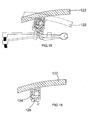
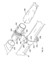
- Figure 19 shows a further embodiment of collar 202 for mounting to the rigid tube 94 and mounting the rigid tube 94 to the housing 4.
- Parts common to the embodiment of Figures 11 and 12 are denoted by like reference numerals but increased by 100.
- the collar 202 is formed as two separate parts, a first part 240 formed as an injection moulded split ring and a tubular second part 242 which is removably attachable to the first part 240.
- the first part 240 has a tubular section 244 which is placed around the tube 94 and is formed on one side with latching portion 204 having inclined surface 206.
- the latching portion is formed as a hollow component to enable the first part 240 to be injection moulded while having sufficient strength.
- the first part 240 is also provided with a generally rectangular projection 246 divided by a groove 248 at the split part of tubular section 244, the projection 246 being arranged opposite the latching portion 204.
- the second part 242 has an annular collar 250 having a slot 252 having an open end 254 and a closed end (not shown) for receiving the rectangular projection 246 on first part 240.
- the collar 250 surrounds a tubular body portion 256 having open ends for receiving an accessory 258, 260 at each end in an interference fit.
- the slot 252 can be mounted to the projection 246 from either direction, thus permitting left and right handed use of the collar 202, and the second part 242 is correctly located on the first part 240 by means of the closed end (not shown) of slot 252 and engagement of a projection (not shown) in slot 252 with groove 248 in projection 246.
- the orientation of the slot 252 relative to the body portion 256 is such that the body portion 256 and the accessories 258, 260 extend generally parallel to the longitudinal axis of tube 94. In this way, space can be particularly efficiently used for storing accessories 258, 260 on tube 94. Furthermore, by providing a collar 202 which serves the dual functions of mounting accessories 258, 260 to tube 94, and mounting tube 94 to the housing by means of latching portion 204, only a single component need by constructed, which reduces the cost of manufacturing the vacuum cleaner incorporating collar 202.
- Figures 13 to 18 show in more detail the floor cleaning head 96 shown in Figure 11.
- the cleaning head 96 has a connector portion 112 pivotally mounted to a head portion 114, so that the angle of the connector portion 112 relative to the head portion 114 can be adjusted, as shown in Figures 13 and 14.
- a brush plate 116 carries a brush member 118 and is connected to a pivot 120 located at the rear of the head portion 114.
- the position of the brush member 118 relative to the head portion 114 is adjusted by means of a lever 122 ( Figures 15 to 18) carrying actuator member 124 which pivots about axis 126 to move a projection 128 on actuator member 124 along an inclined surface 130 of brush plate 116.
- This causes pivotal movement of brush plate 116 about pivot 120 to move the brush member 118 between “brush up” and “brush down” positions.
- the brush plate 116 is urged into the "brush up” and “brush down” positions by means of suitable springs (not shown).
- the body portion 256 of Figure 19 may extend generally at right angles to the longitudinal axis of tube 94.
Abstract
Description
- The present invention relates to vacuum cleaners, and relates particularly, but not exclusively, to cylinder type vacuum cleaners.
- In conventional cylinder type vacuum cleaners, a motor arranged in a housing of the vacuum cleaner drives a fan, which causes air to be displaced radially outwards of the fan and expelled through vents in the housing. This in turn causes suction upstream of the fan, which draws dirty air into the vacuum cleaner housing, through a suitable filter such as a rigid filter unit or a flexible filter bag, the filter being located between an inlet of the housing and the fan. As a result, dirty air is drawn along a suitable accessory such as a flexible hose connected to the housing inlet, enters the inlet and passes through the filter, and cleaner air passes through the fan and is expelled through the vents in the housing.
- A vacuum cleaner of this type is disclosed in WO 02/43553, in which a housing is formed from three parts, a tank element, a middle chassis element, and a top cover element, and a fan causes dirty air to be drawn into the housing and through a duct adjacent the base of the housing between the filter and an inlet to the fan. Vacuum cleaners of this type suffer from the drawback that formation of the duct adjacent the base of the housing is a difficult procedure if the housing is to be injection moulded from plastics material, and moulds for forming the housing requires a large number of complicated components, as a result of which the housing becomes very costly to make, and/or it is difficult to provide an injection moulded housing with sufficient rigidity and strength for use as vacuum cleaners.
- Preferred embodiments of the present invention seek to overcome the above disadvantages of the prior art.
- According to an aspect of the present invention, there is provided a housing for a vacuum cleaner, the housing comprising:-
- (i) a first housing part defining:
- a first chamber having at least one first inlet for intake of air and at least one first outlet for exhaust of air, wherein said first chamber is adapted to accommodate filter means for removing particles larger than a predetermined size from air flowing from at least one said first inlet to at least one said first outlet;
- a second chamber having at least one second inlet for intake of air and at least one second outlet for exhaust of air, wherein said second chamber is adapted to accommodate suction means for causing air to flow from at least one said first inlet to at least one said second outlet; and
- at least one recess formed in an external wall of said first housing part and connecting at least one said first outlet to at least one said second inlet; and
- (ii) at least one second housing part for closing the or each said recess to define at least one duct for directing air exhausted from the or each said first outlet to at least one said second inlet.
- By providing at least one recess, connecting the or each first outlet with at least one second inlet, in an external wall of the first housing part, and by closing the recess by means of one or more second housing parts to define a duct directing air from the or each first outlet to at least one second inlet, this provides the advantage of simplifying injection moulding of the housing compared with prior art arrangements, thus reducing the cost of manufacture of a vacuum cleaner incorporating the housing. In addition, the housing can be injection moulded with the required strength and rigidity.
- At least one said second housing part may comprise valve means for allowing intake of air from the atmosphere into said duct if the pressure difference between said duct and the atmosphere exceeds a predetermined level.
- This provides the advantage of allowing bypass airflow, to prevent overheating of the vacuum cleaner motor if an inlet or a filter of the vacuum cleaner should become blocked or restricted.
- The first housing part may further define a trough surrounding at least one said first outlet.
- This provides the advantage of minimising the extent to which dirt falls into the duct when a filter is removed from the housing.
- In a preferred embodiment, the cross-sectional area of the duct in a direction transverse to the direction of airflow is greater than the total cross-sectional area of the or each said second inlet.
- This provides the advantage of minimising turbulence in airflow through the duct.
- The housing may further comprise sealing means for sealing between the periphery of the or each said recess and the or each said second housing part.
- The housing may further comprise restriction means for restricting access to at least one said second inlet.
- This provides the advantage of preventing entry of dirt into the motor.
- Said restriction means may comprise at least one grille.
- According to another aspect of the present invention, there is provided a vacuum cleaner comprising:
- a housing as defined above;
- filter means arranged in said first chamber for removing particles larger than a predetermined size from air flowing from at least one said first inlet to at least one said first outlet; and
- suction means arranged in said second chamber for causing air to flow from at least one said first inlet to at least one said second outlet.
- A preferred embodiment of the invention will now be described, by way of example only and not in any limitative sense, with reference to the accompanying drawings, in which:-
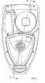
- Figure 1 is a plan view of a vacuum cleaner embodying the present invention;
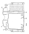
- Figure 2 is a partially cut away plan view of the vacuum cleaner housing of Figure 1;
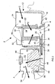
- Figure 3 is a view along the line A-A in Figure 2;
- Figure 4 is a side view of the vacuum cleaner of Figure 1;
- Figure 5 is a sectional view along the line C-C in Figure 1 with internal components of the vacuum cleaner removed;
- Figure 6 is a sectional view along the line B-B in Figure 1 with internal components of the vacuum cleaner removed;
- Figure 7 is a plan view of a removable dirt container lid of the vacuum cleaner of Figure 1;
- Figure 8 is a sectional view along the line D- D in Figure 7;
- Figure 9 is a sectional view, corresponding to Figure 8, but with the filter element removed;
- Figure 10 is a cross-sectional view of a "filter full" indicator mechanism of the vacuum cleaner of Figure 1;
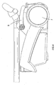
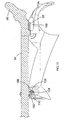
- Figure 11 is a sectional view of part of the housing of the vacuum cleaner of Figure 1, with a floor-cleaning accessory mounted to the housing;
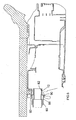
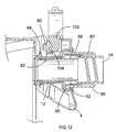
- Figure 12 is a cross-sectional view showing connection of a flexible hose to an inlet of the housing of the vacuum cleaner of Figure 1;
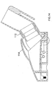
- Figure 13 is a cross-sectional view of a cleaning head of the floor-cleaning accessory of Figure 11 with a rigid tube connected thereto in a lowered position;
- Figure 14 is a sectional view, corresponding to Figure 13, of the cleaning head of Figure 13 with the rigid tube connected thereto in a raised position;
- Figure 15 is a schematic illustration of the operation of a mechanism for moving a brush plate between "brush up" and "brush down" positions in the cleaning head of Figure 13;
- Figure 16 is a schematic side view, corresponding to Figure 15, of the brush plate and actuator mechanism in the "brush up" position;
- Figure 17 is a schematic side view showing the brush plate and actuator mechanism in the "brush down" position;
- Figure 18 is a schematic side cross-sectional view of the actuator mechanism of Figures 15 to 17; and
- Figure 19 is a perspective view of a device for mounting accessories to the vacuum cleaner for storage.
- Referring to Figures 1 to 4, a cylinder
type vacuum cleaner 2 has ahousing 4 having amain housing part 5, acarrying handle 6 andwheels 7. Acable winder switch 8 and ON/OFF switch 10 are provided on an upper part of the housing. - The
housing 4 defines aninlet 12 for connection to a flexible hose 14 (Figure 12) at one end of the housing. Adirt collection receptacle 16 is removably attached to thehousing 4 by means of a suitable latching mechanism (not shown) and defines adirt collection chamber 18. Thereceptacle 16 has a central raisedportion 20 for sealing engagement with acylindrical filter element 22 formed from pleated fibrous material, such as paper or textile, covered by a breathable fabric, and is closed by alid 24 which sealingly engagesupper part 26 offilter element 22 by means of anannular seal 28, the annular seal surrounding avent 30 in thelid 24, the function of which will be described in greater detail below. Thelid 24 also has anedge 32 for gripping by a user during lifting of the lid. - The
dirt collection unit 16 is held in position by the latching mechanism against aninner wall 34 of a recess integrally formed with themain part 5 of thehousing 4. The raisedportion 20 of thedirt collection unit 16 has acentral aperture 36 cooperating with an aperture inupper wall 34 ofrecess 36, the raisedportion 20 being surrounded by first 40 and second 42 trough regions for collecting dirt, in a manner which will be described in greater detail below. - A
motor chamber 44 communicates withrecess 36 via anaperture 46, and amotor 48 is mounted viasealing mounts 50 for rotation about anaxis 52. A fan (not shown) is mounted coaxially withmotor 48 and communicates viaexhaust outlet 54 with the atmosphere. A filter cassette (not shown) containing a hepa filter is mounted inoutlet 54 for filtering air expelled out of theoutlet 54 by means of the fan. - The
recess 36 is closed by means ofclosure plate 56, which is mounted to themain housing part 4, and is provided with abypass valve 58 for allowing entry of air intorecess 36 if the air pressure withinrecess 36 falls below a predetermined value. In this way, themain housing part 4 can be easily injection moulded, theinner wall 34 forming a recessed part of themain housing part 4. Therecess 36 is then closed by means ofclosure plate 56 so that therecess 36 defines a duct between theoutlet 38 offilter unit 22 and an inlet of themotor chamber 44. - The operation of the
vacuum cleaner 2 will now be described. - Actuation of
motor 46 by means of ON/OFF switch 10 causes the fan to radially displace air out ofoutlets 54 in the direction of arrow A shown in Figure 3. As a result, suction is caused upstream of the fan, which draws air fromrecess 36 generally axially intomotor chamber 44 in the direction of arrow B. This in turn causes dirty air to be drawn through inlet 12 (to which a suitable accessory such as a floor cleaning head (Figure 5) is connected by means of a flexible hose (Figure 12)), and is drawn intodirt collection chamber 18 in the direction of arrow C and then inwardly through the walls offilter unit 22 in the direction of arrows D and E. Because ofannular seal 28 surroundingvent 30, the only source of air to themotor chamber 44 at negative pressure is viainlet 12. - The air filtered by
filter unit 22 then passes out ofaperture 38 and along the duct defined byrecess 36 in the direction of arrow F. If theinlet 12 should become blocked (for example as a result of an obstacle coming into contact with it) the resulting pressure difference between the interior ofrecess 36 and the atmosphere causesbypass valve 58 to allow air to enter therecess 36 to preventmotor 46 from overheating. The air path from theinlet 12 to theoutlet 38 via thefilter unit 22 is shown in more detail in Figure 8. - Referring now to Figure 10, a "filter full"
indicator mechanism 60 is mounted toclosure plate 56 inrecess 36 at a part of the closure plate having atransparent window portion 62. Theindicator mechanism 60 comprises ahousing 64 having anopening 66 into which air enters from externally of the vacuumcleaner housing 4 by means of a suitable valve, which may be the by-pass valve shown in Figure 3. Thehousing 64 has anoutlet 68 open to the interior ofrecess 36, and is provided with a greenperforated cover member 70 which can slide axially relative to a redperforated flag member 72, which has aflange 74 abutting a correspondingrecess 76 in thehousing 64. Acover member 70 is urged over theflag member 72 by means of acompression spring 78. - In normal operation of the vacuum cleaner (i.e. in the absence of blockages in the air flow path and with clean filters in the filter unit 22), the difference in air pressure between the
outlet 68 and theinlet 66 is insufficient to displace thecover member 70 from theflag member 72 against the force ofcompression spring 78. However, as thefilter unit 22 becomes blocked by dirt, the difference in pressure between therecess 36 and the atmosphere (and therefore between theoutlet 68 and the inlet 66) increases, as a result of which thecover member 70 is displaced against the force ofspring 78 fromflag member 72, and the redcoloured flag member 72 can then be seen viatransparent portion 62, providing the user with a visual indication that the filter needs to be cleaned. - Referring back to Figure 3, in order to clean the filter, the user lifts
lid 24 by means of grippingportion 32, and then removesfilter unit 22 anddirt collection chamber 16. Because the central portion of thedirt collection chamber 16 is raised, dirt trapped on the outer surface offilter unit 22 has a tendency to fall intotrough regions outlet 38. If themotor 46 should accidentally be actuated when thefilter unit 22 is removed, the opening provided by openedlid 24 is nearer tooutlet 38 thaninlet 12, as a result of which relatively clean air from the atmosphere passes intorecess 36 in preference to dirty air from theinlet 12, thus minimising the risk of themotor 46 being damaged by dirt. Even if thelid 24 should swing shut, relatively clean air passing throughvent 30 still passes intoduct 36 in preference to dirty air frominlet 12, in the absence offilter unit 22 blocking the path of air through thevent 30 by means ofseal 28. This arrangement is shown in more detail in Figure 9. - Referring now to Figures 5 and 12, the
flexible hose 14 is connected tohousing inlet 12 by means of ahose connection moulding 80 having a radiallyinner part 82 which cooperates with a rubber seal 84 (which also forms a seal with dirt collection chamber 16) and a radiallyouter part 86 which is provided withresilient fingers 88 havingheads 90, which locate behindedge portions 92 of themain housing part 4 to hold theconnector 80 in position. In order to release theconnector 80 from thehousing 4, theresilient fingers 88 are pushed radially inwards until theheads 90 are released from thecorresponding edge parts 92, so that theconnector 80 can be axially withdrawn from theinlet 12. - Figures 11 and 12 show a
rigid tube 94 carrying afloor cleaning head 96 removably mounted to thehousing 4 for storage by locating anelongate projection 98 provided on cleaninghead 96 in acorresponding recess 100 onhousing 4. Acollar 102 surroundingtube 94 has a latchingportion 104 and aninclined surface 106, and cooperates with a spring loaded latchingportion 108 onhousing 4 having correspondinginclined surface 110. Movement of the upper part of thetube 94 shown in Figure 11 in the direction of arrow G causes mutual engagement of latchingportion 104 andinclined surface 110, as a result of which latchingportion 108 is displaced against the action of a spring (not shown) to cause latchingportion 104 to be latched in position behind latchingmember 108 withinclined surfaces tube 94 from thehousing 4, a release catch (not shown) is depressed to displace latchingmember 108 against the action of the spring so that the latchingportion 104 ofcollar 102 can be withdrawn from the housing. - Figure 19 shows a further embodiment of
collar 202 for mounting to therigid tube 94 and mounting therigid tube 94 to thehousing 4. Parts common to the embodiment of Figures 11 and 12 are denoted by like reference numerals but increased by 100. - The
collar 202 is formed as two separate parts, afirst part 240 formed as an injection moulded split ring and a tubularsecond part 242 which is removably attachable to thefirst part 240. Thefirst part 240 has atubular section 244 which is placed around thetube 94 and is formed on one side with latchingportion 204 having inclinedsurface 206. The latching portion is formed as a hollow component to enable thefirst part 240 to be injection moulded while having sufficient strength. Thefirst part 240 is also provided with a generallyrectangular projection 246 divided by agroove 248 at the split part oftubular section 244, theprojection 246 being arranged opposite the latchingportion 204. - The
second part 242 has anannular collar 250 having aslot 252 having anopen end 254 and a closed end (not shown) for receiving therectangular projection 246 onfirst part 240. Thecollar 250 surrounds atubular body portion 256 having open ends for receiving anaccessory slot 252 can be mounted to theprojection 246 from either direction, thus permitting left and right handed use of thecollar 202, and thesecond part 242 is correctly located on thefirst part 240 by means of the closed end (not shown) ofslot 252 and engagement of a projection (not shown) inslot 252 withgroove 248 inprojection 246. The orientation of theslot 252 relative to thebody portion 256 is such that thebody portion 256 and theaccessories tube 94. In this way, space can be particularly efficiently used for storingaccessories tube 94. Furthermore, by providing acollar 202 which serves the dual functions of mountingaccessories tube 94, and mountingtube 94 to the housing by means of latchingportion 204, only a single component need by constructed, which reduces the cost of manufacturing the vacuumcleaner incorporating collar 202. - Figures 13 to 18 show in more detail the
floor cleaning head 96 shown in Figure 11. The cleaninghead 96 has aconnector portion 112 pivotally mounted to ahead portion 114, so that the angle of theconnector portion 112 relative to thehead portion 114 can be adjusted, as shown in Figures 13 and 14. - A
brush plate 116 carries abrush member 118 and is connected to apivot 120 located at the rear of thehead portion 114. The position of thebrush member 118 relative to thehead portion 114 is adjusted by means of a lever 122 (Figures 15 to 18) carryingactuator member 124 which pivots aboutaxis 126 to move aprojection 128 onactuator member 124 along aninclined surface 130 ofbrush plate 116. This causes pivotal movement ofbrush plate 116 aboutpivot 120 to move thebrush member 118 between "brush up" and "brush down" positions. Thebrush plate 116 is urged into the "brush up" and "brush down" positions by means of suitable springs (not shown). - It will be appreciated by persons skilled in the art that the above embodiment has been described by way of example only, and not in any limitative sense, and that various alterations and modifications are possible without departure from the scope of the invention as defined by the appended claims. For example, the
body portion 256 of Figure 19 may extend generally at right angles to the longitudinal axis oftube 94.
Claims (9)
- A housing for a vacuum cleaner, the housing comprising:-(i) a first housing part defining:a first chamber having at least one first inlet for intake of air and at least one first outlet for exhaust of air, wherein said first chamber is adapted to accommodate filter means for removing particles larger than a predetermined size from air flowing from at least one said first inlet to at least one said first outlet;a second chamber having at least one second inlet for intake of air and at least one second outlet for exhaust of air, wherein said second chamber is adapted to accommodate suction means for causing air to flow from at least one said first inlet to at least one said second outlet; andat least one recess formed in an external wall of said first housing part and connecting at least one said first outlet to at least one said second inlet; and(ii) at least one second housing part for closing the or each said recess to define at least one duct for directing air exhausted from the or each said first outlet to at least one said second inlet.
- A housing according to claims 1, wherein at least one said second housing part comprises valve means for allowing intake of air from the atmosphere into said duct if the pressure difference between said duct and the atmosphere exceeds a predetermined level.
- A housing according to claim 1 or 2, wherein the first housing part further defines a trough surrounding at least one said first outlet.
- A housing according to any one of the preceding claims, wherein the cross-sectional area of the duct in a direction transverse to the direction of airflow is greater than the total cross-sectional area of the or each said second inlet.
- A housing according to any one of the preceding claims, further comprising sealing means for sealing between the periphery of the or each said recess and the or each said second housing part.
- A housing according to any one of the preceding claims, further comprising restriction means for restricting access to at least one said second inlet.
- A housing according to claim 6, wherein said restriction means comprises at least one grille.
- A housing for a vacuum cleaner, the housing substantially as hereinbefore described with reference to the accompanying drawings.
- A vacuum cleaner comprising:a housing according to any one of the preceding claims;filter means arranged in said first chamber for removing particles larger than a predetermined size from air flowing from at least one said first inlet to at least one said first outlet; andsuction means arranged in said second chamber for causing air to flow from at least one said first inlet to at least one said second outlet.
Applications Claiming Priority (4)
| Application Number | Priority Date | Filing Date | Title |
|---|---|---|---|
| GB0314930 | 2003-06-26 | ||
| GB0314930A GB0314930D0 (en) | 2003-06-26 | 2003-06-26 | Vacuum cleaner |
| GB0317674 | 2003-07-29 | ||
| GB0317674A GB0317674D0 (en) | 2003-06-26 | 2003-07-29 | Vacuum cleaner |
Publications (3)
| Publication Number | Publication Date |
|---|---|
| EP1491127A2 true EP1491127A2 (en) | 2004-12-29 |
| EP1491127A3 EP1491127A3 (en) | 2008-10-15 |
| EP1491127B1 EP1491127B1 (en) | 2012-10-17 |
Family
ID=33420901
Family Applications (1)
| Application Number | Title | Priority Date | Filing Date |
|---|---|---|---|
| EP04014042A Not-in-force EP1491127B1 (en) | 2003-06-26 | 2004-06-16 | Vacuum cleaner |
Country Status (4)
| Country | Link |
|---|---|
| US (1) | US7383606B2 (en) |
| EP (1) | EP1491127B1 (en) |
| AU (1) | AU2004202719B2 (en) |
| NZ (1) | NZ533716A (en) |
Cited By (1)
| Publication number | Priority date | Publication date | Assignee | Title |
|---|---|---|---|---|
| EP2829210A3 (en) * | 2013-07-23 | 2015-04-15 | Festool GmbH | Suction device with a main filter |
Families Citing this family (3)
| Publication number | Priority date | Publication date | Assignee | Title |
|---|---|---|---|---|
| US7555811B2 (en) * | 2005-07-28 | 2009-07-07 | Panasonic Corporation Of North America | Floor cleaning apparatus equipped with removable half-plenum |
| WO2008030565A2 (en) | 2006-09-07 | 2008-03-13 | Opentv, Inc. | Method and system to navigate viewable content |
| US20130219652A1 (en) * | 2012-02-28 | 2013-08-29 | Steve Martel | Valve system and method |
Citations (2)
| Publication number | Priority date | Publication date | Assignee | Title |
|---|---|---|---|---|
| US2388279A (en) | 1943-09-27 | 1945-11-06 | Air Way Electric Appl Corp | Suction cleaner |
| WO2002043553A1 (en) | 2000-12-01 | 2002-06-06 | Nilfisk-Advance A/S | A coupling device for a detachable connection of a suction hose to a vacuum cleaner housing |
Family Cites Families (6)
| Publication number | Priority date | Publication date | Assignee | Title |
|---|---|---|---|---|
| US2515425A (en) * | 1946-03-21 | 1950-07-18 | Air Way Electric Appl Corp | Auxiliary valve for suction cleaners |
| US2688379A (en) * | 1952-02-27 | 1954-09-07 | Landers Frary & Clark | Vacuum cleaner |
| US2771151A (en) * | 1953-08-11 | 1956-11-20 | Ralph C Osborn | Vacuum cleaner |
| DE2848750C2 (en) * | 1978-11-10 | 1984-08-16 | Licentia Patent-Verwaltungs-Gmbh, 6000 Frankfurt | vacuum cleaner |
| KR100432730B1 (en) * | 2001-10-15 | 2004-05-24 | 엘지전자 주식회사 | Device for protecting moter in vacuum cleaner |
| KR100445803B1 (en) | 2002-02-05 | 2004-08-25 | 삼성광주전자 주식회사 | Air exhaust structure of an upright-type vacuum cleaner |
-
2004
- 2004-06-16 EP EP04014042A patent/EP1491127B1/en not_active Not-in-force
- 2004-06-21 AU AU2004202719A patent/AU2004202719B2/en not_active Ceased
- 2004-06-23 NZ NZ533716A patent/NZ533716A/en unknown
- 2004-06-25 US US10/876,825 patent/US7383606B2/en not_active Expired - Fee Related
Patent Citations (2)
| Publication number | Priority date | Publication date | Assignee | Title |
|---|---|---|---|---|
| US2388279A (en) | 1943-09-27 | 1945-11-06 | Air Way Electric Appl Corp | Suction cleaner |
| WO2002043553A1 (en) | 2000-12-01 | 2002-06-06 | Nilfisk-Advance A/S | A coupling device for a detachable connection of a suction hose to a vacuum cleaner housing |
Cited By (1)
| Publication number | Priority date | Publication date | Assignee | Title |
|---|---|---|---|---|
| EP2829210A3 (en) * | 2013-07-23 | 2015-04-15 | Festool GmbH | Suction device with a main filter |
Also Published As
| Publication number | Publication date |
|---|---|
| NZ533716A (en) | 2005-11-25 |
| AU2004202719A1 (en) | 2005-01-20 |
| AU2004202719B2 (en) | 2010-07-22 |
| EP1491127A3 (en) | 2008-10-15 |
| EP1491127B1 (en) | 2012-10-17 |
| US7383606B2 (en) | 2008-06-10 |
| US20050022334A1 (en) | 2005-02-03 |
Similar Documents
| Publication | Publication Date | Title |
|---|---|---|
| US11006797B1 (en) | Station | |
| US7517377B2 (en) | Dust collecting unit for use in cleaner | |
| US7669282B2 (en) | Vacuum cleaner | |
| US7581286B2 (en) | Vacuum cleaner and dust collection unit thereof | |
| CN212698706U (en) | Cleaning device and cleaning equipment | |
| US7967884B2 (en) | Bagless dustcup | |
| RU2277372C2 (en) | Dust collector of vacuum-cleaning robot | |
| WO2007146444A1 (en) | Filter cleaning system for a vacuum cleaner | |
| US20230092045A1 (en) | Cleaner | |
| US7462210B2 (en) | Dust collecting unit for vacuum cleaner | |
| US7478456B2 (en) | Mounting device for vacuum cleaner accessory | |
| EP1493374B1 (en) | Vacuum cleaner with means for preventing motor damage | |
| EP1491127B1 (en) | Vacuum cleaner | |
| US11426044B1 (en) | Cleaning device | |
| KR20190000620A (en) | Cleaner | |
| JP4269315B2 (en) | Electric vacuum cleaner | |
| KR0133761B1 (en) | Vacuum cleaner for wet-dry type | |
| KR20220140315A (en) | Cleaner |
Legal Events
| Date | Code | Title | Description |
|---|---|---|---|
| PUAI | Public reference made under article 153(3) epc to a published international application that has entered the european phase |
Free format text: ORIGINAL CODE: 0009012 |
|
| AK | Designated contracting states |
Kind code of ref document: A2 Designated state(s): AT BE BG CH CY CZ DE DK EE ES FI FR GB GR HU IE IT LI LU MC NL PL PT RO SE SI SK TR |
|
| AX | Request for extension of the european patent |
Extension state: AL HR LT LV MK |
|
| PUAL | Search report despatched |
Free format text: ORIGINAL CODE: 0009013 |
|
| AK | Designated contracting states |
Kind code of ref document: A3 Designated state(s): AT BE BG CH CY CZ DE DK EE ES FI FR GB GR HU IE IT LI LU MC NL PL PT RO SE SI SK TR |
|
| AX | Request for extension of the european patent |
Extension state: AL HR LT LV MK |
|
| 17P | Request for examination filed |
Effective date: 20081022 |
|
| AKX | Designation fees paid |
Designated state(s): AT BE BG CH CY CZ DE DK EE ES FI FR GB GR HU IE IT LI LU MC NL PL PT RO SE SI SK TR |
|
| 17Q | First examination report despatched |
Effective date: 20101116 |
|
| GRAP | Despatch of communication of intention to grant a patent |
Free format text: ORIGINAL CODE: EPIDOSNIGR1 |
|
| GRAS | Grant fee paid |
Free format text: ORIGINAL CODE: EPIDOSNIGR3 |
|
| GRAA | (expected) grant |
Free format text: ORIGINAL CODE: 0009210 |
|
| AK | Designated contracting states |
Kind code of ref document: B1 Designated state(s): AT BE BG CH CY CZ DE DK EE ES FI FR GB GR HU IE IT LI LU MC NL PL PT RO SE SI SK TR |
|
| REG | Reference to a national code |
Ref country code: GB Ref legal event code: FG4D |
|
| REG | Reference to a national code |
Ref country code: CH Ref legal event code: EP |
|
| REG | Reference to a national code |
Ref country code: IE Ref legal event code: FG4D |
|
| REG | Reference to a national code |
Ref country code: AT Ref legal event code: REF Ref document number: 579497 Country of ref document: AT Kind code of ref document: T Effective date: 20121115 |
|
| REG | Reference to a national code |
Ref country code: NL Ref legal event code: T3 |
|
| REG | Reference to a national code |
Ref country code: DE Ref legal event code: R096 Ref document number: 602004039667 Country of ref document: DE Effective date: 20121213 |
|
| REG | Reference to a national code |
Ref country code: AT Ref legal event code: MK05 Ref document number: 579497 Country of ref document: AT Kind code of ref document: T Effective date: 20121017 |
|
| PG25 | Lapsed in a contracting state [announced via postgrant information from national office to epo] |
Ref country code: SE Free format text: LAPSE BECAUSE OF FAILURE TO SUBMIT A TRANSLATION OF THE DESCRIPTION OR TO PAY THE FEE WITHIN THE PRESCRIBED TIME-LIMIT Effective date: 20121017 Ref country code: ES Free format text: LAPSE BECAUSE OF FAILURE TO SUBMIT A TRANSLATION OF THE DESCRIPTION OR TO PAY THE FEE WITHIN THE PRESCRIBED TIME-LIMIT Effective date: 20130128 Ref country code: FI Free format text: LAPSE BECAUSE OF FAILURE TO SUBMIT A TRANSLATION OF THE DESCRIPTION OR TO PAY THE FEE WITHIN THE PRESCRIBED TIME-LIMIT Effective date: 20121017 |
|
| PG25 | Lapsed in a contracting state [announced via postgrant information from national office to epo] |
Ref country code: SI Free format text: LAPSE BECAUSE OF FAILURE TO SUBMIT A TRANSLATION OF THE DESCRIPTION OR TO PAY THE FEE WITHIN THE PRESCRIBED TIME-LIMIT Effective date: 20121017 Ref country code: PT Free format text: LAPSE BECAUSE OF FAILURE TO SUBMIT A TRANSLATION OF THE DESCRIPTION OR TO PAY THE FEE WITHIN THE PRESCRIBED TIME-LIMIT Effective date: 20130218 Ref country code: BE Free format text: LAPSE BECAUSE OF FAILURE TO SUBMIT A TRANSLATION OF THE DESCRIPTION OR TO PAY THE FEE WITHIN THE PRESCRIBED TIME-LIMIT Effective date: 20121017 Ref country code: GR Free format text: LAPSE BECAUSE OF FAILURE TO SUBMIT A TRANSLATION OF THE DESCRIPTION OR TO PAY THE FEE WITHIN THE PRESCRIBED TIME-LIMIT Effective date: 20130118 Ref country code: PL Free format text: LAPSE BECAUSE OF FAILURE TO SUBMIT A TRANSLATION OF THE DESCRIPTION OR TO PAY THE FEE WITHIN THE PRESCRIBED TIME-LIMIT Effective date: 20121017 Ref country code: CY Free format text: LAPSE BECAUSE OF FAILURE TO SUBMIT A TRANSLATION OF THE DESCRIPTION OR TO PAY THE FEE WITHIN THE PRESCRIBED TIME-LIMIT Effective date: 20121017 |
|
| PG25 | Lapsed in a contracting state [announced via postgrant information from national office to epo] |
Ref country code: AT Free format text: LAPSE BECAUSE OF FAILURE TO SUBMIT A TRANSLATION OF THE DESCRIPTION OR TO PAY THE FEE WITHIN THE PRESCRIBED TIME-LIMIT Effective date: 20121017 |
|
| PG25 | Lapsed in a contracting state [announced via postgrant information from national office to epo] |
Ref country code: CZ Free format text: LAPSE BECAUSE OF FAILURE TO SUBMIT A TRANSLATION OF THE DESCRIPTION OR TO PAY THE FEE WITHIN THE PRESCRIBED TIME-LIMIT Effective date: 20121017 Ref country code: BG Free format text: LAPSE BECAUSE OF FAILURE TO SUBMIT A TRANSLATION OF THE DESCRIPTION OR TO PAY THE FEE WITHIN THE PRESCRIBED TIME-LIMIT Effective date: 20130117 Ref country code: SK Free format text: LAPSE BECAUSE OF FAILURE TO SUBMIT A TRANSLATION OF THE DESCRIPTION OR TO PAY THE FEE WITHIN THE PRESCRIBED TIME-LIMIT Effective date: 20121017 Ref country code: DK Free format text: LAPSE BECAUSE OF FAILURE TO SUBMIT A TRANSLATION OF THE DESCRIPTION OR TO PAY THE FEE WITHIN THE PRESCRIBED TIME-LIMIT Effective date: 20121017 Ref country code: EE Free format text: LAPSE BECAUSE OF FAILURE TO SUBMIT A TRANSLATION OF THE DESCRIPTION OR TO PAY THE FEE WITHIN THE PRESCRIBED TIME-LIMIT Effective date: 20121017 |
|
| PLBE | No opposition filed within time limit |
Free format text: ORIGINAL CODE: 0009261 |
|
| STAA | Information on the status of an ep patent application or granted ep patent |
Free format text: STATUS: NO OPPOSITION FILED WITHIN TIME LIMIT |
|
| PG25 | Lapsed in a contracting state [announced via postgrant information from national office to epo] |
Ref country code: RO Free format text: LAPSE BECAUSE OF FAILURE TO SUBMIT A TRANSLATION OF THE DESCRIPTION OR TO PAY THE FEE WITHIN THE PRESCRIBED TIME-LIMIT Effective date: 20121017 Ref country code: IT Free format text: LAPSE BECAUSE OF FAILURE TO SUBMIT A TRANSLATION OF THE DESCRIPTION OR TO PAY THE FEE WITHIN THE PRESCRIBED TIME-LIMIT Effective date: 20121017 |
|
| 26N | No opposition filed |
Effective date: 20130718 |
|
| REG | Reference to a national code |
Ref country code: DE Ref legal event code: R097 Ref document number: 602004039667 Country of ref document: DE Effective date: 20130718 |
|
| PG25 | Lapsed in a contracting state [announced via postgrant information from national office to epo] |
Ref country code: MC Free format text: LAPSE BECAUSE OF FAILURE TO SUBMIT A TRANSLATION OF THE DESCRIPTION OR TO PAY THE FEE WITHIN THE PRESCRIBED TIME-LIMIT Effective date: 20121017 |
|
| REG | Reference to a national code |
Ref country code: CH Ref legal event code: PL |
|
| REG | Reference to a national code |
Ref country code: IE Ref legal event code: MM4A |
|
| PG25 | Lapsed in a contracting state [announced via postgrant information from national office to epo] |
Ref country code: IE Free format text: LAPSE BECAUSE OF NON-PAYMENT OF DUE FEES Effective date: 20130616 Ref country code: CH Free format text: LAPSE BECAUSE OF NON-PAYMENT OF DUE FEES Effective date: 20130630 Ref country code: LI Free format text: LAPSE BECAUSE OF NON-PAYMENT OF DUE FEES Effective date: 20130630 |
|
| PG25 | Lapsed in a contracting state [announced via postgrant information from national office to epo] |
Ref country code: TR Free format text: LAPSE BECAUSE OF FAILURE TO SUBMIT A TRANSLATION OF THE DESCRIPTION OR TO PAY THE FEE WITHIN THE PRESCRIBED TIME-LIMIT Effective date: 20121017 |
|
| PG25 | Lapsed in a contracting state [announced via postgrant information from national office to epo] |
Ref country code: HU Free format text: LAPSE BECAUSE OF FAILURE TO SUBMIT A TRANSLATION OF THE DESCRIPTION OR TO PAY THE FEE WITHIN THE PRESCRIBED TIME-LIMIT; INVALID AB INITIO Effective date: 20040616 Ref country code: LU Free format text: LAPSE BECAUSE OF NON-PAYMENT OF DUE FEES Effective date: 20130616 |
|
| REG | Reference to a national code |
Ref country code: FR Ref legal event code: PLFP Year of fee payment: 13 |
|
| REG | Reference to a national code |
Ref country code: FR Ref legal event code: PLFP Year of fee payment: 14 |
|
| PGFP | Annual fee paid to national office [announced via postgrant information from national office to epo] |
Ref country code: DE Payment date: 20170613 Year of fee payment: 14 Ref country code: FR Payment date: 20170511 Year of fee payment: 14 Ref country code: GB Payment date: 20170614 Year of fee payment: 14 |
|
| PGFP | Annual fee paid to national office [announced via postgrant information from national office to epo] |
Ref country code: NL Payment date: 20170614 Year of fee payment: 14 |
|
| REG | Reference to a national code |
Ref country code: DE Ref legal event code: R119 Ref document number: 602004039667 Country of ref document: DE |
|
| REG | Reference to a national code |
Ref country code: NL Ref legal event code: MM Effective date: 20180701 |
|
| GBPC | Gb: european patent ceased through non-payment of renewal fee |
Effective date: 20180616 |
|
| PG25 | Lapsed in a contracting state [announced via postgrant information from national office to epo] |
Ref country code: NL Free format text: LAPSE BECAUSE OF NON-PAYMENT OF DUE FEES Effective date: 20180701 |
|
| PG25 | Lapsed in a contracting state [announced via postgrant information from national office to epo] |
Ref country code: GB Free format text: LAPSE BECAUSE OF NON-PAYMENT OF DUE FEES Effective date: 20180616 Ref country code: DE Free format text: LAPSE BECAUSE OF NON-PAYMENT OF DUE FEES Effective date: 20190101 Ref country code: FR Free format text: LAPSE BECAUSE OF NON-PAYMENT OF DUE FEES Effective date: 20180630 |