EP1490127B1 - Suction sequences for a breastpump - Google Patents
Suction sequences for a breastpump Download PDFInfo
- Publication number
- EP1490127B1 EP1490127B1 EP03707992A EP03707992A EP1490127B1 EP 1490127 B1 EP1490127 B1 EP 1490127B1 EP 03707992 A EP03707992 A EP 03707992A EP 03707992 A EP03707992 A EP 03707992A EP 1490127 B1 EP1490127 B1 EP 1490127B1
- Authority
- EP
- European Patent Office
- Prior art keywords
- breastpump
- segment
- cycle
- vacuum
- curve
- Prior art date
- Legal status (The legal status is an assumption and is not a legal conclusion. Google has not performed a legal analysis and makes no representation as to the accuracy of the status listed.)
- Expired - Lifetime
Links
Images


Classifications
-
- A—HUMAN NECESSITIES
- A61—MEDICAL OR VETERINARY SCIENCE; HYGIENE
- A61M—DEVICES FOR INTRODUCING MEDIA INTO, OR ONTO, THE BODY; DEVICES FOR TRANSDUCING BODY MEDIA OR FOR TAKING MEDIA FROM THE BODY; DEVICES FOR PRODUCING OR ENDING SLEEP OR STUPOR
- A61M1/00—Suction or pumping devices for medical purposes; Devices for carrying-off, for treatment of, or for carrying-over, body-liquids; Drainage systems
- A61M1/06—Milking pumps
- A61M1/069—Means for improving milking yield
- A61M1/0693—Means for improving milking yield with programmable or pre-programmed sucking patterns
- A61M1/06935—Means for improving milking yield with programmable or pre-programmed sucking patterns imitating the suckling of an infant
-
- A—HUMAN NECESSITIES
- A61—MEDICAL OR VETERINARY SCIENCE; HYGIENE
- A61M—DEVICES FOR INTRODUCING MEDIA INTO, OR ONTO, THE BODY; DEVICES FOR TRANSDUCING BODY MEDIA OR FOR TAKING MEDIA FROM THE BODY; DEVICES FOR PRODUCING OR ENDING SLEEP OR STUPOR
- A61M1/00—Suction or pumping devices for medical purposes; Devices for carrying-off, for treatment of, or for carrying-over, body-liquids; Drainage systems
- A61M1/06—Milking pumps
- A61M1/069—Means for improving milking yield
- A61M1/0697—Means for improving milking yield having means for massaging the breast
-
- A—HUMAN NECESSITIES
- A61—MEDICAL OR VETERINARY SCIENCE; HYGIENE
- A61M—DEVICES FOR INTRODUCING MEDIA INTO, OR ONTO, THE BODY; DEVICES FOR TRANSDUCING BODY MEDIA OR FOR TAKING MEDIA FROM THE BODY; DEVICES FOR PRODUCING OR ENDING SLEEP OR STUPOR
- A61M1/00—Suction or pumping devices for medical purposes; Devices for carrying-off, for treatment of, or for carrying-over, body-liquids; Drainage systems
- A61M1/71—Suction drainage systems
- A61M1/74—Suction control
- A61M1/75—Intermittent or pulsating suction
-
- A—HUMAN NECESSITIES
- A61—MEDICAL OR VETERINARY SCIENCE; HYGIENE
- A61M—DEVICES FOR INTRODUCING MEDIA INTO, OR ONTO, THE BODY; DEVICES FOR TRANSDUCING BODY MEDIA OR FOR TAKING MEDIA FROM THE BODY; DEVICES FOR PRODUCING OR ENDING SLEEP OR STUPOR
- A61M2205/00—General characteristics of the apparatus
- A61M2205/35—Communication
- A61M2205/3546—Range
- A61M2205/3569—Range sublocal, e.g. between console and disposable
-
- A—HUMAN NECESSITIES
- A61—MEDICAL OR VETERINARY SCIENCE; HYGIENE
- A61M—DEVICES FOR INTRODUCING MEDIA INTO, OR ONTO, THE BODY; DEVICES FOR TRANSDUCING BODY MEDIA OR FOR TAKING MEDIA FROM THE BODY; DEVICES FOR PRODUCING OR ENDING SLEEP OR STUPOR
- A61M2205/00—General characteristics of the apparatus
- A61M2205/35—Communication
- A61M2205/3576—Communication with non implanted data transmission devices, e.g. using external transmitter or receiver
- A61M2205/3584—Communication with non implanted data transmission devices, e.g. using external transmitter or receiver using modem, internet or bluetooth
-
- A—HUMAN NECESSITIES
- A61—MEDICAL OR VETERINARY SCIENCE; HYGIENE
- A61M—DEVICES FOR INTRODUCING MEDIA INTO, OR ONTO, THE BODY; DEVICES FOR TRANSDUCING BODY MEDIA OR FOR TAKING MEDIA FROM THE BODY; DEVICES FOR PRODUCING OR ENDING SLEEP OR STUPOR
- A61M2205/00—General characteristics of the apparatus
- A61M2205/50—General characteristics of the apparatus with microprocessors or computers
- A61M2205/52—General characteristics of the apparatus with microprocessors or computers with memories providing a history of measured variating parameters of apparatus or patient
-
- A—HUMAN NECESSITIES
- A61—MEDICAL OR VETERINARY SCIENCE; HYGIENE
- A61M—DEVICES FOR INTRODUCING MEDIA INTO, OR ONTO, THE BODY; DEVICES FOR TRANSDUCING BODY MEDIA OR FOR TAKING MEDIA FROM THE BODY; DEVICES FOR PRODUCING OR ENDING SLEEP OR STUPOR
- A61M2205/00—General characteristics of the apparatus
- A61M2205/82—Internal energy supply devices
- A61M2205/8206—Internal energy supply devices battery-operated
Definitions
- This invention relates to breastpumps for drawing breastmilk, and particularly to a motorized, such as electrically driven, breastpump.
- breastpumps for use by nursing mothers are well known. They allow the nursing woman to express the breastmilk as necessary or convenient, and further provide collection of the breastmilk for later use. For some mothers, breastpumps may be a necessity, such as when the child has suckling problems, or if the mother has problems with excessive or deficient milk production, or soreness, deformation or injury of the mammilla.
- Manual breastpumps are commonplace, primarily because they are relatively inexpensive and easy to transport. Being manually driven, however, stroke rate and suction pressure produced can be uneven, and operating the pump can ultimately be tiring.
- Electrically-driven breastpumps are also commonplace. They may be of a substantially large size of a non-portable or semi-portable type, typically including a vacuum pump which has an electric motor that plugs into standard house current. Advantages of this type of pump are ready controllability and regulation of the vacuum, and the ability to pump both breasts at once. That is, the nursing woman has both hands free to hold two breastpump shields in place for pumping of both breasts at the same time.
- Battery-driven breastpumps have also been developed. These breastpumps have the advantages of controllability and regulation of the vacuum, as well as being easily carried.
- a battery-driven portable breastpump is described in U.S. 4,964,851 , for example.
- This breastpump, sold under the name MINIELECTRIC by Medela, Inc. is lightweight and achieves good vacuum (i.e., negative pressure) regulation in preferred limits, for example, between about 30 and about 300 mmHg.
- the LACTINA breastpump sold by Medela, Inc. is also another type of breast pump which may be driven by battery as well as house current. It is generally disclosed in U.S. Patent No. 5,007,899 .
- Some breastpumps provide the user with the ability to vary the amount of vacuum being applied, as well as the speed of the pumping action (i.e., number of cycles per minute). In some instances in the prior art, speed and vacuum level may influence each other, such that as speed increases so does the vacuum level.
- speed and vacuum level may influence each other, such that as speed increases so does the vacuum level.
- the basic "curve” remains fixed, however, and the user must adapt as best she.can to making variations within that particular curve built into the machine, which typically has been generalized for the overall population of users.
- WO 01/047577 provides a breastpump which can be programmed to generate, among other things, a plurality of differing milk expression (extraction) sequences, or curves. It discloses a breastpump comprising a breastshield having a portion within which a woman's breast is received for the expression of milk. A source of vacuum is in communication with the breastshield. There is a mechanism for operating the source of vacuum according to a first sequence, and a controller for operating the source of vacuum according to a second sequence.
- the controller can have a present program for the second sequence which is a milk ejection sequence, for example.
- the breastpumps has a plurality of different programs for the controller wherein each program has a different sequence.
- a motorized pump e.g., compressed air, battery and/or house current
- a microprocessor-based controller e.g., compressed air, battery and/or house current
- Cards, with memory "chips,” containing different suction curves adapted for varying conditions and objectives are included for programming the controller in this embodiment.
- a user selects a desired program, and that card is then read by a mechanism providing input to the controller.
- suction curves are generally addressed in the first instance herein, the milk expression sequences may also include a positive pressure aspect.
- the programming could also be provided via other media, including discs, CDs, infrared data transfer, electronic feed (e.g., an Internet connection), and so forth.
- a significant, and heretofore unavailable advantage realized is the ready ability to modify the breastpump suction action to a variety of desired conditions, and provide this ability to the end-user.
- An attendant advantage is that, as the science of breastpumping continues to make advances, new and improved suction curves and sequences can be made available on further cards, or other program-inputting means.
- the programmable pump can also record data relating to its use and operation. That data could be stored, for instance, and then retrieved as by downloading through an Internet connection, magnetic recording (disk or card), and the like. This data retrieval would be useful in medical research, for updating the pump with new data, for monitoring usage, just for some instances.
- a program could be made of a particular infant's suckling pattern. That program could then be used to operate the pump, and then varied over time as the infant grows.
- an improved breastpump which has a pre-programmed milk ejection sequence.
- the ejection sequence is most advantageously made available through a button or the like provided on the breastpump used to actuate the sequence.
- a breastpump assembly of the prior art in one form has an aesthetically pleasing and compact design.
- the housing for the major components of the assembly is a casing 10 made of a rigid high impact plastic. As shown, it has a generally ellipsoidal cross-section along its vertical axis, yielding a pleasing smooth curving look to the casing exterior.
- the casing 10 is closed at its upper end by an upper housing part 11, to which is affixed a carrying handle 12.
- carrying handle 12 has a pair of cradles 15 formed in opposite ends thereof. These cradles 15 are adapted to receive and support the funnel portions 16 of respective breastshields 17.
- These breastshields 17 (sometimes referred to themselves as breastpumps) are of the type shown and described in U.S. Patent No. 4,964,851 and 4,929,229 , for instance. Further detail regarding the breastshields 17 may be obtained through reference to those patents, but will be omitted herein since the invective features in point in this application are not contingent upon the breastshield being used, so long as it is suitable to the task of milk expression.
- the breastshields 17 have the aforementioned funnel portion 16 which communicates with conduit structure connecting to a container (bottle) 18.
- This particular breastshield 17 is adapted for both manual as well as motorized pumping. It has a collar 20 to which a manually-driven piston pump (not shown) is screw-threaded for attachment and use in one mode of operation.
- a manually-driven piston pump (not shown) is screw-threaded for attachment and use in one mode of operation.
- a port provided inside of the collar 20 which is in communication with the funnel portion, and to which a tube from the vacuum pump is releasably connected to convey vacuum to the breastshield.
- the widened (conical) portion of the breastshield 17 is placed on the breast for drawing vacuum within the shield, and thereby drawing milk through a pulling force applied to the breast. Milk drawn from the breast is collected in the bottle 18.
- FIGS. 15 and 16 show a modified exterior for the breastpump 10' (prime numbers being used herein to refer to similar but modified parts).
- the breastshields 17 are not cradled by the handle 12', but instead are carried in a holder 26 mounted to the back of the unit.
- casing 10 has a drive unit 25 mounted therein.
- drives that may be used for diaphragm pumps such as those used in the instant embodiment.
- the type of pump (diaphragm, piston, etc.) is not necessarily significant to certain aspects of the present invention.
- the driving mechanism for the breastpump shown for the embodiment in point is a linear drive for the diaphragm pumps consisting of a reduction drive arrangement and a 12 V DC-motor 28.
- FIG. 8 embodiment is substantially the same as that of FIGS. 1 through 7 , except for a modified cover for the upper housing, which here includes the rigid shells 24 for the diaphragms 34 as part of the cover 35.
- the diaphragm pumps 30 will be further described hereafter.
- FIG. 17 shows yet another version of a breastpump of the prior art which is substantially the same as that of FIGS. 1 through 8 , except with a modified cover 35" and shell 24" for the diaphragm pump 30.
- the breastshield holder of the FIGS. 15 and 16 embodiment has also been slightly modified. It is with respect to FIG. 17 that the majority of the interior detail of the breastpump will be further understood.
- the reduction gearing contains belts 27a, 27b and 27c. Power is transferred from the shaft 29 of motor 28 to belt 27a.
- Belt 27a is received in a channel of wheel 51, which is mounted to the drive chassis 62 on rotatable shaft 52. Shaft 52 is fixed to rotate with wheel 51.
- a freewheel 53 is mounted on a shaft 54 fixed to the chassis 62 to freely rotate, and engages the outside of belt 27a, producing more surface engagement by the belt 27a with wheel 51.
- Shaft 52 has a small toothed gear 55 mounted thereon.
- Belt 27b is toothed, and engages the gear 55. Toothed belt 27b furthermore engages a larger toothed gear 56 fixed to rotating shaft 57 ( FIGS. 22 and 24 ). Part of gear 56 is small toothed gear portion 58.
- Belt 27c which is also toothed, engages gear 58 as well as toothed gear 59.
- Gear 59 is fixedly mounted to rotating shaft 70. Fixed at each end of shaft 70 are small toothed gears 71a, 71b. Toothed belts 72a, 72b respectively engage gears 71a, 71b and freely rotating toothed gears 73a, 73b.
- Diaphragm pusher (push/pull) shafts 74a, 74b are respectively clamped to belts 72a, 72b at one end. The other end engages the interior of a respective diaphragm membrane member 34 ( FIG. 22 , and also see FIGS. 20 and 21(a) ).
- a screw engagement with the shafts 74a, 74b was used, with a threaded nut-like element 37 mounted in a reinforced central area of membrane 36 (again, the diaphragm pumps 30 are described in more detail below). Both of the pusher shafts 74a, 74b move in tandem as driven by respective belts 72a, 72b.
- belt 27a rotates shaft 52 via wheel 51.
- Belt 27b is in turn thereby driven off of smaller gear 55, causing rotation of shaft 57, which in turn rotates larger gear 56 and its smaller part 58, to thereby turn shaft 70 via belt 27c which couples gear part 58 with larger gear 59.
- a forward and then backward stroke is generated, through reversal of the motor shaft 29 direction. Reduction gearing is thus obtained as desired through appropriate selection of the various gears/wheels noted above.
- position sensing mechanism 78 which can be of any standard and well known variety.
- This sensing mechanism 78 uses a toothed wheel 78a mounted to the shaft 29 of motor 28, which is registered by counter 78b. Signals generated by the counter 78b are processed by the cpu of the breastpump.
- a negative pressure, or vacuum, is generated in a pair of diaphragm pumps 30.
- Each diaphragm pump has a flexible membrane 34 mounted in the upper housing 11 assembled with a respective rigid shell 24 (and see FIGS. 20 and 21(a) through 21(c) described further below).
- the membrane and shell are in substantially airtight engagement
- a vacuum is generated in the space between the shell interior and the membrane, which can be accessed through outlet port 31 formed on the shell, to which a tube 32 is connected to communicate the vacuum to a respective breastshield 17.
- Power is provided either through ordinary house current via power cord 38, or electrochemical battery 39, such as a pair of 6V, 1.2Ah lead-acid type rechargeable batteries.
- Power cord 38 is provided on a wrap-around mount conveniently located for storage in a well in the bottom of the lower housing part 13.
- FIG. 7 shows wells 41 formed within the lower housing 13 through which the batteries 40 are inserted into receptacles formed within the casing 10, having covers 42 for the wells.
- FIG. 7 omits the detail of the wrap mount 40, for clarity.
- An on-off switch or knob 45 (and see FIG. 9 ) is provided on the casing, which can be rotary or push-button to that end. It is nonetheless rotary and push-button in this embodiment since it also acts to control the amount of vacuum being applied.
- a signal is generated which increases or decreases the level of vacuum (suction force) to be applied, depending on which way the knob is turned.
- suction force the level of vacuum
- rate the rate and force are inversely related. This is considered to have a beneficial effect.
- the knob is pushed in for on and off.
- a LCD display 48 is visible from the exterior of the casing 10 .
- a milk ejection button 49 is used to activate a pre-programmed suction sequence (described in hereinafter) particularly adapted for ejection and stimulate the milk ejection reflex.
- the slot 50 provides the interface access for programming cards used with the breastpump of this invention.
- the display 48 provides visual indications of various functions of the pump. This could include, for example, the type of sequence then programmed, the level of suction force, the battery condition, and so forth.
- the two diaphragm pumps 30 are in a well formed in the top of the casing 10.
- a cover 35 also 35' and 35" (again, primed numbers being substantially similar to their un-primed counterparts) is provided which fits over the well and is generally flush with the upper housing part 11.
- the outlets 31 extend through relieved areas in the cover 35, for example, for easy access in use.
- the shells 24 are shown formed in the cover of the embodiment of FIG. 8 .
- the FIG. 17 example has the shells 24 mounted in a removable manner in the upper housing, as through a snap fit or interference engagement, such as shown in the embodiment of FIGS. 20 and 21(a) through 21 (c) , to allow easier access for cleaning or replacing the membranes of the pumping mechanism, and for cleaning the shells themselves (which are provided with grips 33 to these ends).
- diaphragm member or membrane 34 which may be made of any suitably durable flexible and durable fluid-impervious material (to be airtight), such as silicone with a Shore A hardness in the range of 30 to 70, is molded around its perimeter to a rigid plastic collar 85.
- Collar 85 has a plurality of depending anchor posts 86 with outboard flanges formed thereon, which engage with the inside lip of the respective well in the upper housing part 11 within which the collar 85 is received to snap-fit the membrane 34 in place.
- Prophylactic (protective) disposable/cleanable covers 36 are additionally and advantageously provided, which form-fit over the diaphragms 34 and isolate them from air and other fluid from the breastshields.
- the covers 36 which can be made of the same material as the membranes but thinner, are likewise fluid-impervious.
- each of the covers 36 has an upturned cuff 87 which forms an annular well around the perimeter of the cover 36.
- Uppermost bead 88 engages in an annular rim channel 90 formed along the bottom outside of shell 24', for a substantially airtight engagement between the protective cover 36 and the shell.
- An interior channel 93 is formed within the interior bottom of the cover 36 by a bead 91 and shoulder 92, which each run circumferentially around the cover. This interior channel 93 is received on a slightly protruding edge or rim on the collar 85 of the membrane 34. An airtight fit is thus provided between the protective cover 36 and the membrane 34, which also serves to releasably fix the shell 24 in place over the membrane 34, and complete the diaphragm pump 30.
- a one-way valve 95 is provided in the membrane 34, which communicates with the possible space that may form between the membrane 34 and overlying cover 36. This valve permits any entrapped air therebetween to be exhausted, such as if the first stroke on start-up happens to be toward the shell 24, with the protective cover 36 thereafter then following the movement of the diaphragm 34 to which it will generally be in facial engagement.
- the breastpump utilizes a microprocessor-based system indicated at 60 which is provided user input through a plurality of "chip" cards 61.
- Each chip card contains one or more predetermined programs recorded on an EEPROM.
- each card could contain a specific type of sequence along with a milk ejection sequence.
- An EEPROM microcontroller of the type MB90562 may be used, for one example, or the Atmel 2-wire EEPROM chipcard microcontroller AT24C164 for another. These provide about 16K of memory, which is considered presently sufficient.
- the programs (some examples of which are described hereafter) are recorded in a conventional manner, and would be provided to the mother ready to use.
- the programmed chip card is inserted into the slot 50 in the back of the casing 10, where it engages an interface to the microprocessor.
- the particular program on the selected chip card 61 is then communicate to the microprocessor 60.
- Microprocessor 60 is integrated with the drive unit 25 to effect operation of the drive unit in accordance with the selected program, drawing upon either the AC power source as converted via standard technology to DC (indicated at 68 in FIG. 9 ), or from the battery source 39.
- the microprocessor 60 can also control power management.
- Suction force (e.g., the amount of negative pressure generated) will typically also be adjustable by the user via operation of the rotary control knob 45, as noted above.
- a pre-set range for the suction force will nonetheless ordinarily be provided in the program as an initial setting, for adjustment by the user thereafter via the knob 45.
- milk ejection sequence milk ejection reflex
- the milk ejection sequence (described below) is pre-programmed in the microprocessor 60, or may otherwise be wired into the circuitry in a manner to override the then-existing operating program.
- the mother desires to engage this sequence, she presses the button 49, which produces and sends an electrical signal, as to the microprocessor 60.
- the ejection program is then effected.
- a chip card 61 is but one way to program the microprocessor 60.
- Other input means could be used, such as more dedicated buttons like button 49, each set to actuate a given sequence pre-programmed into the microprocessor 60.
- a numeric pad could be provided to input a code.
- the programs could be provided through an electronic data link, such as a modem, or optically, or otherwise.
- Data can also be recorded by the microprocessor for downloading or transfer to the chip card. Data could also be directly recorded on the chip card. For instance, it is contemplated that the suckling action of a particular child could be recorded and reduced to a sequence. That sequence could then be programmed into the pump, and the mother would then have a suckling action from the pump very reminiscent of her own child.
- the chip card 61a with breastpump operation data thereon is then read (downloaded) at a "card station" 75, shown here as a card reader 76 linked to a computer 77.
- the computer 77 is used to transfer the data to one of a variety of available media, such as CD, floppy disk, etc. for physical transfer to a research or data monitoring facility, here indicated at 80.
- the data could also simply be transferred via modem through an Internet interface.
- FIGS. 11 through 15 An example of the kind of methods that such cycle could represent comprises FIGS. 11 through 15 .
- FIG. 11 is what is referred to by Medela, Inc. as the "Standard Classic Program". This is a method for operating a breastpump that has been developed which is considered to provide a general optimal suction curve reminiscent of an infant's normal suckling, such as provided by the 015 "CLASSIC" breastpump sold by Medela, Inc. As indicated in the graph of FIG. 11 , negative pressure is along the y-axis (in millimeters of mercury) and time (in seconds) along the x-axis. In this particular method, the cycles are fixed at about 47 per minute; the amount of suction is generally adjustable between about 100 to about 250 mmHg.
- FIG. 12 illustrates what can be termed as a "Sore Nipple Program” method.
- the lower end of the vacuum range is reduced to about 20 mmHg, and the overall suction cycle is extended in duration, i.e., from a low of about 25 cycles/min. to about 40.
- the overall suction cycle is extended in duration, i.e., from a low of about 25 cycles/min. to about 40.
- For a lower vacuum applied in this program there is an increase in the number of cycles. In general, however, there is a slower and gentler suction compared with the "CLASSIC" program of FIG. 11 .
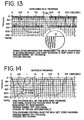
- FIG. 13 shows a method for operating a breastpump which is considered to yield an increase in milk output. This is a program that might be applied between regular pump sessions several times a day.
- the breastpump is operated at a rapid cyclical rate on the order of about 120 cycles/min., preferably with a pause after a period of vacuum application; here, 10 seconds of vacuum, then a 2 second pause.
- the negative pressure is in the range of about 50 to about 150 mmHg. Note the detail in the inset of FIG. 13 showing the rapidity and steep slopes of the vacuum application.
- FIG. 14 What has been termed a "Superior Program" for operating a breastpump is illustrated in FIG. 14 .
- a vacuum range of about 100 to about 250 mmHg has been chosen, with cycles ranging from about 47 to about 78 per minute.
- the cycle rate and the vacuum are tied, such that as, for instance, the cycles decrease, the amount of vacuum increases, i.e., there is an inverse relationship.
- this program differs from the "CLASSIC" program above in part through a sequence that initially reaches a peak negative pressure, then smoothly starts a pressure increase (less negative) along a similar (although opposite) slope to that of the negative pressure build-up, but then slows the pressure increase briefly, before continuing on essentially the initial slope for the negative pressure release.
- a milk ejection sequence is also incorporated in this "Superior Program," and utilizes a vacuum range of about 40 to about 220 mmHg, with cycles ranging between about 80 to about 160 per minute and preferably at about 120 cycles per minute.
- the above programs are disclosed in WO 01/47577 .
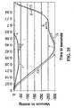
- FIG. 25 A preferred embodiment of a vacuum cycle for the purpose of eliciting milk expression by generating a cyclical pressure change with a breastpump is shown in FIG. 25 .
- a range of vacuum operation of the breastpump from a minimum curve A to a maximum curve B.
- both extremes of operation defined by curves A and B include identical or nearly identical curve envelopes.
- the envelope (the shape) of the vacuum curve over time does not change, that is, the overall pattern of the vacuum values produced over time in the breastpump does not change regardless of the amplitude. Therefore, a single mathematical expression may be used to describe the envelope of the expression cycle, which may be varied in duration and amplitude as shown.
- the duration of the expression cycle shown in FIG. 25 varies from 0.61 to 0.95 seconds from curves A to B.
- the amplitude of the minimum cycle A varies from 0 mmHg to about -36 mmHg and the maximum cycle B from 0 mmHg to about -297 mmHg.
- the duration of the cycle varies in proportion to the peak vacuum generated.
- FIG. 25 includes two separate curves that generally define the boundaries of a range of expression curves lying within having the same envelope or overall shape or pattern.
- a first curve A which pressure varies from 0 mmHg (atmospheric) to about -36 mmHg (vacuum) shows the vacuum generated during the cycle and in particular, a lower limit for the effective expression of breast milk with the curve envelope described.
- a second curve B which ranges in pressure from 0 mmHg to about -297 mmHg, represents the highest limit of the vacuum generated for the effective expression of breast milk. It can be seen that the minimum and maximum curves A, B differ in amplitude and cycle duration but share a common envelope, shape or pattern.
- a first segment S1 includes a major portion having an essentially linear negative slope leading to a peak vacuum point P.
- a second segment, S2 includes a major portion having an essentially linear positive slope after the peak vacuum point P.
- a flat rest segment R follows segment S2, characterized by no change in vacuum.
- the rest segment R is a portion of the curve having no change in pressure at a time in each cycle during about 60 to about 80 percent of the duration of the cycle. It can be seen from the illustrated maximum curve B that the rest segment occurs from about 0.63 seconds to about 0.75 seconds. Accordingly, the rest segment R occurs from about 66 percent to about 79 percent of the total cycle duration in the maximum curve B. With respect to the minimum curve A, the rest segment R occurs from about 0.40 seconds to about 0.49 seconds. Accordingly, the rest segment R spans from about 63 percent to about 77 percent of the total cycle duration in the minimum curve.
- a third segment, S3, follows the rest segment R and includes a major portion that is essentially a linear positive slope leading to a return to atmospheric pressure, the slope of S3 being more steep that the slope of S2.
- the time duration of each of the cycles varies with the amplitude of the vacuum.
- the time duration of the entire cycle is correspondingly greater.
- the time duration of the cycle ranges from about 0.63 seconds to about 0.9 seconds (minimum to maximum curve).
- each cycle may be spaced by a rest period at or near atmospheric pressure.
- the time of each rest period may be from about 0.1 to about 2.0 seconds. More preferably, the rest period is about 0.25 seconds. Including the rest period, the entire cycle sequence may be performed from about 50-75 times or cycles per minute (CPM).
- a preferred vacuum cycle for stimulating the milk ejection reflex by generating a rapid cyclical pressure change with a breastpump is shown in the graph of FIG. 26 .
- the graph includes two separate curves, but with the same envelope or overall pattern.
- a first curve C which ranges in pressure from 0 mmHg (atmospheric) to about -45 mmHg (vacuum), the minimum curve C, represents the lower limit of the range of the vacuum cycle (lower amount of peak vacuum).
- a second curve D which ranges in pressure from 0 mmHg to about -225 mmHg, the maximum curve D, represents the high limit of the range of the vacuum cycle (highest amount of peak vacuum).
- the minimum and maximum curves C, D differ in amplitude and share an envelope.
- Both the minimum and maximum curves shown in FIG. 26 may be represented by the mathematical expression of Equation 1, a polynomial, by using the values given in Table 2 below: Table 2 A 10 A 9 A 8 A 7 A 6 Maximum curve 0 0 15000000 -34920000 32800000 Minimum curve 0 0 15000000 -34920000 32800000 A 5 A 4 A 3 A 2 A 1 Maximum curve -16040000 4340000 -616300 37000 -1000 Minimum curve -16040000 4340000 -616300 37000 -1000 A 0 T V Maximum curve 8 0.95 1.3 Minimum curve 8 1 0.25
- the time duration of each of the minimum and maximum cycles C, D does not vary with the amplitude of the vacuum.
- the time duration of the entire cycle is the same as that of curve having a lesser peak amplitude.
- the time duration of the cycle remains at 0.5 seconds whether at the minimum or maximum range of vacuum operation.
- no rest period is provided between cycles.
- the frequency of operation of the breastpump remains at about 120 CPM, since there is no pause between cycles in the preferred embodiment.
- a rest period of 0.0 to 0.5 seconds is provided between vacuum cycles.
Abstract
Description
- This invention relates to breastpumps for drawing breastmilk, and particularly to a motorized, such as electrically driven, breastpump.
- Breastpumps for use by nursing mothers are well known. They allow the nursing woman to express the breastmilk as necessary or convenient, and further provide collection of the breastmilk for later use. For some mothers, breastpumps may be a necessity, such as when the child has suckling problems, or if the mother has problems with excessive or deficient milk production, or soreness, deformation or injury of the mammilla.
- Manual breastpumps are commonplace, primarily because they are relatively inexpensive and easy to transport. Being manually driven, however, stroke rate and suction pressure produced can be uneven, and operating the pump can ultimately be tiring.
- Electrically-driven breastpumps are also commonplace. They may be of a substantially large size of a non-portable or semi-portable type, typically including a vacuum pump which has an electric motor that plugs into standard house current. Advantages of this type of pump are ready controllability and regulation of the vacuum, and the ability to pump both breasts at once. That is, the nursing woman has both hands free to hold two breastpump shields in place for pumping of both breasts at the same time.
- Battery-driven breastpumps have also been developed. These breastpumps have the advantages of controllability and regulation of the vacuum, as well as being easily carried. Such a battery-driven portable breastpump is described in
U.S. 4,964,851 , for example. This breastpump, sold under the name MINIELECTRIC by Medela, Inc., is lightweight and achieves good vacuum (i.e., negative pressure) regulation in preferred limits, for example, between about 30 and about 300 mmHg. The LACTINA breastpump sold by Medela, Inc. is also another type of breast pump which may be driven by battery as well as house current. It is generally disclosed inU.S. Patent No. 5,007,899 . - Electrically driven motorized breastpumps have almost universally been developed with a single type of "cycle" for a given pump. That is, the driving mechanism for generating the vacuum (negative pressure) to be applied at the breast in the more sophisticated pumps is geared to a particular sequence, or curve, of negative pressure increase (i.e., increasing suction), and then release. This is often aimed at reproducing in some sense the suckling action of an infant, for instance. Breastpumping can cover a range of different conditions, however, such as where the mother's nipples are sore for some reason, there is a state of significant engorgement, some nipple stimulation may be particularly desired, ejection and relaxation may be of particular interest, it may be desired to increase milk production, and so on.
- Some breastpumps provide the user with the ability to vary the amount of vacuum being applied, as well as the speed of the pumping action (i.e., number of cycles per minute). In some instances in the prior art, speed and vacuum level may influence each other, such that as speed increases so does the vacuum level. The basic "curve" remains fixed, however, and the user must adapt as best she.can to making variations within that particular curve built into the machine, which typically has been generalized for the overall population of users.
-
WO 01/047577 - The controller can have a present program for the second sequence which is a milk ejection sequence, for example. Preferably, the breastpumps has a plurality of different programs for the controller wherein each program has a different sequence.
- In one example, a motorized pump (e.g., compressed air, battery and/or house current) is provided with a microprocessor-based controller. Cards, with memory "chips," containing different suction curves adapted for varying conditions and objectives are included for programming the controller in this embodiment. A user selects a desired program, and that card is then read by a mechanism providing input to the controller. It should be noted that while suction curves are generally addressed in the first instance herein, the milk expression sequences may also include a positive pressure aspect. The programming could also be provided via other media, including discs, CDs, infrared data transfer, electronic feed (e.g., an Internet connection), and so forth.
- A significant, and heretofore unavailable advantage realized is the ready ability to modify the breastpump suction action to a variety of desired conditions, and provide this ability to the end-user. An attendant advantage is that, as the science of breastpumping continues to make advances, new and improved suction curves and sequences can be made available on further cards, or other program-inputting means.
- Yet another attendant advantage is that the programmable pump can also record data relating to its use and operation. That data could be stored, for instance, and then retrieved as by downloading through an Internet connection, magnetic recording (disk or card), and the like. This data retrieval would be useful in medical research, for updating the pump with new data, for monitoring usage, just for some instances.
- Further, a program could be made of a particular infant's suckling pattern. That program could then be used to operate the pump, and then varied over time as the infant grows.
- In yet another example an improved breastpump is disclosed which has a pre-programmed milk ejection sequence. The ejection sequence is most advantageously made available through a button or the like provided on the breastpump used to actuate the sequence.
- It is an object of the invention to provide a method for operating a breastpump with one or more novel suction sequences which are considered to produce advantageous particularized results. Such sequences are defined in the appended claims.
- These and other features and advantages of the present invention will be further understood and appreciated when considered in relation to the following detailed description of embodiments of the invention, taken in conjunction with the drawings, in which:
-
- FIG. is a front perspective view of a breastpump assembly according to the prior art;
-
FIG. 2 is a side elevational view of the breastpump ofFIG. 1 ; -
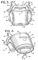
FIG. 3 is a rear perspective view of the breastpump ofFIG. 1 ; -
FIG. 4 is a perspective view of the breastpump ofFIG. 1 looking at the bottom; -
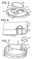
FIG. 5 is a top view of the breastpump ofFIG. 1 with a cover removed revealing diaphragm pumps; -
FIG. 6 is an enlarged side view of the breastpump ofFIG. 1 adjacent the bottom highlighting the program card insert slot; -
FIG. 7 is a bottom perspective view of the breastpump ofFIG. 1 showing battery arrangement; -
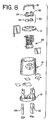
FIG. 8 is a somewhat exploded assembly view of the major components of the breastpump ofFIGS. 1 through 5 , with a modified top cover for the diaphragm pump assembly; -
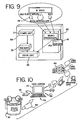
FIG. 9 is a diagrammatic representation of the interaction of various components with the controller; -
FIG. 10 is a schematic-type representation of a data stooge and retrieval process that can be effected in accordance with the prior art; -
FIGS. 11 through 14 are various methods (curves) for operating the breastpump to differing ends; -
FIG. 15 is a front perspective view of another embodiment of a breastpump assembly according to the prior art. -
FIG. 16 is a rear perspective view of theFIG. 15 embodiment; -
FIG. 17 is a somewhat exploded assembly view of the major components of yet another breastpump made in accordance with the prior art; -
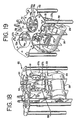
FIG. 18 is an enlarged front perspective view of the motor drive of the breastpump ofFIG. 17 ; -
FIG. 19 is a view similar to that ofFIG. 18 but from a top perspective; -
FIG. 20 is an enlarged assembly view of the diaphragm pump mechanism; -
FIG. 21 (a) is a cross-sectional view of the assembled diaphragm pump ofFIG. 20 ; -
FIG. 21(b) is an elevational view of the assembled diaphragm pump ofFIG. 20 ; -
FIG. 21(c) is a top view of the assembled diaphragm pump ofFIG. 20 ; -
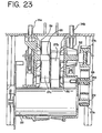
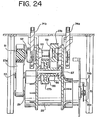
FIG. 22 is a sectional view of the assembled breastpump ofFIG. 17 taken through the middle of the breastpump along its long lateral axis (side to side) looking rearwardly; -
FIG. 23 is a sectional view similar to that ofFIG. 22 taken along a plane forwardly of that ofFIG. 22 ; -
FiG. 24 is a sectional view similar to that ofFIG. 22 taken along a plane behind the electric motor looking back to front; -
FIG. 25 is a graph depicting a method (vacuum cycle) for operating a breastpump to elicit milk expression according to the invention, and -
FIG. 26 is a graph depicting a method (vacuum, cycle) for operating a breastpump to elicit a milk ejection reflex according to the invention. - Referring to
FIGS. 1 through 7 initially, a breastpump assembly of the prior art in one form has an aesthetically pleasing and compact design. The housing for the major components of the assembly is acasing 10 made of a rigid high impact plastic. As shown, it has a generally ellipsoidal cross-section along its vertical axis, yielding a pleasing smooth curving look to the casing exterior. Thecasing 10 is closed at its upper end by anupper housing part 11, to which is affixed a carryinghandle 12. - In this first embodiment, carrying
handle 12 has a pair ofcradles 15 formed in opposite ends thereof. Thesecradles 15 are adapted to receive and support thefunnel portions 16 ofrespective breastshields 17. These breastshields 17 (sometimes referred to themselves as breastpumps) are of the type shown and described inU.S. Patent No. 4,964,851 and4,929,229 , for instance. Further detail regarding thebreastshields 17 may be obtained through reference to those patents, but will be omitted herein since the invective features in point in this application are not contingent upon the breastshield being used, so long as it is suitable to the task of milk expression. - In general, however, the
breastshields 17 have theaforementioned funnel portion 16 which communicates with conduit structure connecting to a container (bottle) 18. Thisparticular breastshield 17 is adapted for both manual as well as motorized pumping. It has acollar 20 to which a manually-driven piston pump (not shown) is screw-threaded for attachment and use in one mode of operation. When an electrically operated vacuum pump is to be employed, there is a port provided inside of thecollar 20 which is in communication with the funnel portion, and to which a tube from the vacuum pump is releasably connected to convey vacuum to the breastshield. Again, such detail is well known, and can be gleaned from the foregoing patents, among other public sources. In operation in either mode, the widened (conical) portion of thebreastshield 17 is placed on the breast for drawing vacuum within the shield, and thereby drawing milk through a pulling force applied to the breast. Milk drawn from the breast is collected in thebottle 18. -
FIGS. 15 and 16 show a modified exterior for the breastpump 10' (prime numbers being used herein to refer to similar but modified parts). In this version thebreastshields 17 are not cradled by the handle 12', but instead are carried in aholder 26 mounted to the back of the unit. - Referring to
FIG. 8 initially, casing 10 has adrive unit 25 mounted therein. There are, of course, any number of drives that may be used for diaphragm pumps such as those used in the instant embodiment. Indeed, the type of pump (diaphragm, piston, etc.) is not necessarily significant to certain aspects of the present invention. The driving mechanism for the breastpump shown for the embodiment in point, however, is a linear drive for the diaphragm pumps consisting of a reduction drive arrangement and a 12 V DC-motor 28. - It will be noted that the
FIG. 8 embodiment is substantially the same as that ofFIGS. 1 through 7 , except for a modified cover for the upper housing, which here includes therigid shells 24 for thediaphragms 34 as part of thecover 35. The diaphragm pumps 30 will be further described hereafter. -
FIG. 17 shows yet another version of a breastpump of the prior art which is substantially the same as that ofFIGS. 1 through 8 , except with a modifiedcover 35" andshell 24" for thediaphragm pump 30. The breastshield holder of theFIGS. 15 and 16 embodiment has also been slightly modified. It is with respect toFIG. 17 that the majority of the interior detail of the breastpump will be further understood. - Turning now to
FIGS. 18, 19 and22 through 24 in particular, the reduction gearing containsbelts shaft 29 ofmotor 28 tobelt 27a.Belt 27a is received in a channel ofwheel 51, which is mounted to thedrive chassis 62 onrotatable shaft 52.Shaft 52 is fixed to rotate withwheel 51. Afreewheel 53 is mounted on ashaft 54 fixed to thechassis 62 to freely rotate, and engages the outside ofbelt 27a, producing more surface engagement by thebelt 27a withwheel 51. -
Shaft 52 has a smalltoothed gear 55 mounted thereon.Belt 27b is toothed, and engages thegear 55.Toothed belt 27b furthermore engages a largertoothed gear 56 fixed to rotating shaft 57 (FIGS. 22 and24 ). Part ofgear 56 is smalltoothed gear portion 58.Belt 27c, which is also toothed, engagesgear 58 as well astoothed gear 59.Gear 59 is fixedly mounted torotating shaft 70. Fixed at each end ofshaft 70 are small toothed gears 71a, 71b.Toothed belts toothed gears - Diaphragm pusher (push/pull)
shafts belts FIG. 22 , and also seeFIGS. 20 and21(a) ). Here, a screw engagement with theshafts like element 37 mounted in a reinforced central area of membrane 36 (again, the diaphragm pumps 30 are described in more detail below). Both of thepusher shafts respective belts - Accordingly, as
motor drive shaft 29 turns,belt 27a rotatesshaft 52 viawheel 51.Belt 27b is in turn thereby driven off ofsmaller gear 55, causing rotation ofshaft 57, which in turn rotateslarger gear 56 and itssmaller part 58, to thereby turnshaft 70 viabelt 27c which couples gearpart 58 withlarger gear 59. This transfers the motion via gears 71a, 71b tobelts pusher shafts motor shaft 29 direction. Reduction gearing is thus obtained as desired through appropriate selection of the various gears/wheels noted above. - The location of the
shafts position sensing mechanism 78, which can be of any standard and well known variety. Thissensing mechanism 78 uses atoothed wheel 78a mounted to theshaft 29 ofmotor 28, which is registered bycounter 78b. Signals generated by thecounter 78b are processed by the cpu of the breastpump. - A negative pressure, or vacuum, is generated in a pair of diaphragm pumps 30. Each diaphragm pump has a
flexible membrane 34 mounted in theupper housing 11 assembled with a respective rigid shell 24 (and seeFIGS. 20 and21(a) through 21(c) described further below). The membrane and shell are in substantially airtight engagement When themembrane 34 is pulled away from theshell 24, a vacuum is generated in the space between the shell interior and the membrane, which can be accessed throughoutlet port 31 formed on the shell, to which atube 32 is connected to communicate the vacuum to arespective breastshield 17. - Power is provided either through ordinary house current via
power cord 38, orelectrochemical battery 39, such as a pair of 6V, 1.2Ah lead-acid type rechargeable batteries.Power cord 38 is provided on a wrap-around mount conveniently located for storage in a well in the bottom of thelower housing part 13.FIG. 7 showswells 41 formed within thelower housing 13 through which thebatteries 40 are inserted into receptacles formed within thecasing 10, having covers 42 for the wells.FIG. 7 omits the detail of thewrap mount 40, for clarity. - An on-off switch or knob 45 (and see
FIG. 9 ) is provided on the casing, which can be rotary or push-button to that end. It is nonetheless rotary and push-button in this embodiment since it also acts to control the amount of vacuum being applied. As theknob 45 is rotated, a signal is generated which increases or decreases the level of vacuum (suction force) to be applied, depending on which way the knob is turned. In this example, as the suction force is increased, the cycle (rate) is decreased. That is, the rate and force are inversely related. This is considered to have a beneficial effect. The knob is pushed in for on and off. - Additionally visible from the exterior of the
casing 10 is aLCD display 48, amilk ejection button 49, and a program card slot 50 (the ejection sequence and programmable aspects will also be discussed in more detail below). Milk-let downbutton 49 is used to activate a pre-programmed suction sequence (described in hereinafter) particularly adapted for ejection and stimulate the milk ejection reflex. Theslot 50 provides the interface access for programming cards used with the breastpump of this invention. - The
display 48 provides visual indications of various functions of the pump. This could include, for example, the type of sequence then programmed, the level of suction force, the battery condition, and so forth. - In this embodiment, the two
diaphragm pumps 30 are in a well formed in the top of thecasing 10. A cover 35 (also 35' and 35" (again, primed numbers being substantially similar to their un-primed counterparts)) is provided which fits over the well and is generally flush with theupper housing part 11. Theoutlets 31 extend through relieved areas in thecover 35, for example, for easy access in use. - It may be noted that the
shells 24 are shown formed in the cover of the embodiment ofFIG. 8 . TheFIG. 17 example has theshells 24 mounted in a removable manner in the upper housing, as through a snap fit or interference engagement, such as shown in the embodiment ofFIGS. 20 and21(a) through 21 (c) , to allow easier access for cleaning or replacing the membranes of the pumping mechanism, and for cleaning the shells themselves (which are provided withgrips 33 to these ends). - In the
FIG. 17 example, diaphragm member ormembrane 34, which may be made of any suitably durable flexible and durable fluid-impervious material (to be airtight), such as silicone with a Shore A hardness in the range of 30 to 70, is molded around its perimeter to a rigidplastic collar 85.Collar 85 has a plurality of depending anchor posts 86 with outboard flanges formed thereon, which engage with the inside lip of the respective well in theupper housing part 11 within which thecollar 85 is received to snap-fit themembrane 34 in place. - Prophylactic (protective) disposable/cleanable covers 36 are additionally and advantageously provided, which form-fit over the
diaphragms 34 and isolate them from air and other fluid from the breastshields. Thecovers 36, which can be made of the same material as the membranes but thinner, are likewise fluid-impervious. - Referring to
FIGS. 20 and21(a) through 21(c) in particular, each of thecovers 36 has an upturnedcuff 87 which forms an annular well around the perimeter of thecover 36. A pair ofcircumferential beads Uppermost bead 88 engages in anannular rim channel 90 formed along the bottom outside of shell 24', for a substantially airtight engagement between theprotective cover 36 and the shell. - An
interior channel 93 is formed within the interior bottom of thecover 36 by abead 91 andshoulder 92, which each run circumferentially around the cover. Thisinterior channel 93 is received on a slightly protruding edge or rim on thecollar 85 of themembrane 34. An airtight fit is thus provided between theprotective cover 36 and themembrane 34, which also serves to releasably fix theshell 24 in place over themembrane 34, and complete thediaphragm pump 30. - Note also that a one-
way valve 95 is provided in themembrane 34, which communicates with the possible space that may form between themembrane 34 andoverlying cover 36. This valve permits any entrapped air therebetween to be exhausted, such as if the first stroke on start-up happens to be toward theshell 24, with theprotective cover 36 thereafter then following the movement of thediaphragm 34 to which it will generally be in facial engagement. - One significant aspect is the ability to program the breastpump with different types of suction sequences, or cycles as they are sometimes referred to herein. With reference to
FIG. 9 , for instance, the breastpump utilizes a microprocessor-based system indicated at 60 which is provided user input through a plurality of "chip"cards 61. Each chip card contains one or more predetermined programs recorded on an EEPROM. For example, each card could contain a specific type of sequence along with a milk ejection sequence. - An EEPROM microcontroller of the type MB90562 may be used, for one example, or the Atmel 2-wire EEPROM chipcard microcontroller AT24C164 for another. These provide about 16K of memory, which is considered presently sufficient.
- The programs (some examples of which are described hereafter) are recorded in a conventional manner, and would be provided to the mother ready to use. The programmed chip card is inserted into the
slot 50 in the back of thecasing 10, where it engages an interface to the microprocessor. The particular program on the selectedchip card 61 is then communicate to themicroprocessor 60.Microprocessor 60 is integrated with thedrive unit 25 to effect operation of the drive unit in accordance with the selected program, drawing upon either the AC power source as converted via standard technology to DC (indicated at 68 inFIG. 9 ), or from thebattery source 39. Themicroprocessor 60 can also control power management. - Suction force (e.g., the amount of negative pressure generated) will typically also be adjustable by the user via operation of the
rotary control knob 45, as noted above. A pre-set range for the suction force will nonetheless ordinarily be provided in the program as an initial setting, for adjustment by the user thereafter via theknob 45. - One example provides a milk ejection sequence (milk ejection reflex) that can be engaged without need of a chip card for the same. The milk ejection sequence (described below) is pre-programmed in the
microprocessor 60, or may otherwise be wired into the circuitry in a manner to override the then-existing operating program. When the mother desires to engage this sequence, she presses thebutton 49, which produces and sends an electrical signal, as to themicroprocessor 60. The ejection program is then effected. - It will be readily understood that a
chip card 61 is but one way to program themicroprocessor 60. Other input means could be used, such as more dedicated buttons likebutton 49, each set to actuate a given sequence pre-programmed into themicroprocessor 60. A numeric pad could be provided to input a code. The programs could be provided through an electronic data link, such as a modem, or optically, or otherwise. - Data can also be recorded by the microprocessor for downloading or transfer to the chip card. Data could also be directly recorded on the chip card. For instance, it is contemplated that the suckling action of a particular child could be recorded and reduced to a sequence. That sequence could then be programmed into the pump, and the mother would then have a suckling action from the pump very reminiscent of her own child.
- Referring now to
FIG. 10 , the chip card 61a with breastpump operation data thereon is then read (downloaded) at a "card station" 75, shown here as acard reader 76 linked to acomputer 77. Thecomputer 77 is used to transfer the data to one of a variety of available media, such as CD, floppy disk, etc. for physical transfer to a research or data monitoring facility, here indicated at 80. The data could also simply be transferred via modem through an Internet interface. - It can thus be seen that a variety of different suction cycles or sequences can now be provided with the same breastpump equipment An example of the kind of methods that such cycle could represent comprises
FIGS. 11 through 15 . -
FIG. 11 , for instance, is what is referred to by Medela, Inc. as the "Standard Classic Program". This is a method for operating a breastpump that has been developed which is considered to provide a general optimal suction curve reminiscent of an infant's normal suckling, such as provided by the 015 "CLASSIC" breastpump sold by Medela, Inc. As indicated in the graph ofFIG. 11 , negative pressure is along the y-axis (in millimeters of mercury) and time (in seconds) along the x-axis. In this particular method, the cycles are fixed at about 47 per minute; the amount of suction is generally adjustable between about 100 to about 250 mmHg. -
FIG. 12 illustrates what can be termed as a "Sore Nipple Program" method. In comparison toFIG. 11 , it will be seen that the lower end of the vacuum range is reduced to about 20 mmHg, and the overall suction cycle is extended in duration, i.e., from a low of about 25 cycles/min. to about 40. For a lower vacuum applied in this program, there is an increase in the number of cycles. In general, however, there is a slower and gentler suction compared with the "CLASSIC" program ofFIG. 11 . -
FIG. 13 shows a method for operating a breastpump which is considered to yield an increase in milk output. This is a program that might be applied between regular pump sessions several times a day. In this method, the breastpump is operated at a rapid cyclical rate on the order of about 120 cycles/min., preferably with a pause after a period of vacuum application; here, 10 seconds of vacuum, then a 2 second pause. The negative pressure is in the range of about 50 to about 150 mmHg. Note the detail in the inset ofFIG. 13 showing the rapidity and steep slopes of the vacuum application. - What has been termed a "Superior Program" for operating a breastpump is illustrated in
FIG. 14 . A vacuum range of about 100 to about 250 mmHg has been chosen, with cycles ranging from about 47 to about 78 per minute. The cycle rate and the vacuum are tied, such that as, for instance, the cycles decrease, the amount of vacuum increases, i.e., there is an inverse relationship. It will be noted that this program differs from the "CLASSIC" program above in part through a sequence that initially reaches a peak negative pressure, then smoothly starts a pressure increase (less negative) along a similar (although opposite) slope to that of the negative pressure build-up, but then slows the pressure increase briefly, before continuing on essentially the initial slope for the negative pressure release. A milk ejection sequence is also incorporated in this "Superior Program," and utilizes a vacuum range of about 40 to about 220 mmHg, with cycles ranging between about 80 to about 160 per minute and preferably at about 120 cycles per minute. The above programs are disclosed inWO 01/47577 - A preferred embodiment of a vacuum cycle for the purpose of eliciting milk expression by generating a cyclical pressure change with a breastpump is shown in
FIG. 25 . What is shown is a range of vacuum operation of the breastpump from a minimum curve A to a maximum curve B. As will be discussed below, both extremes of operation defined by curves A and B include identical or nearly identical curve envelopes. In other words, while the amplitude and cycle duration of vacuum produced by the breastpump may be varied anywhere between the limits described by curves A and B, the envelope (the shape) of the vacuum curve over time does not change, that is, the overall pattern of the vacuum values produced over time in the breastpump does not change regardless of the amplitude. Therefore, a single mathematical expression may be used to describe the envelope of the expression cycle, which may be varied in duration and amplitude as shown. - The duration of the expression cycle shown in
FIG. 25 varies from 0.61 to 0.95 seconds from curves A to B. The amplitude of the minimum cycle A varies from 0 mmHg to about -36 mmHg and the maximum cycle B from 0 mmHg to about -297 mmHg. The duration of the cycle varies in proportion to the peak vacuum generated. - The expression cycle is optimize for milk expression from a mother's breast. As discussed above,
FIG. 25 includes two separate curves that generally define the boundaries of a range of expression curves lying within having the same envelope or overall shape or pattern. A first curve A, which pressure varies from 0 mmHg (atmospheric) to about -36 mmHg (vacuum) shows the vacuum generated during the cycle and in particular, a lower limit for the effective expression of breast milk with the curve envelope described. A second curve B, which ranges in pressure from 0 mmHg to about -297 mmHg, represents the highest limit of the vacuum generated for the effective expression of breast milk. It can be seen that the minimum and maximum curves A, B differ in amplitude and cycle duration but share a common envelope, shape or pattern. - The envelope of the curves may be described by defining separate adjacent portions or segments of the curves. Generally, a first segment S1, includes a major portion having an essentially linear negative slope leading to a peak vacuum point P. A second segment, S2, includes a major portion having an essentially linear positive slope after the peak vacuum point P. A flat rest segment R follows segment S2, characterized by no change in vacuum. The rest segment R is a portion of the curve having no change in pressure at a time in each cycle during about 60 to about 80 percent of the duration of the cycle. It can be seen from the illustrated maximum curve B that the rest segment occurs from about 0.63 seconds to about 0.75 seconds. Accordingly, the rest segment R occurs from about 66 percent to about 79 percent of the total cycle duration in the maximum curve B. With respect to the minimum curve A, the rest segment R occurs from about 0.40 seconds to about 0.49 seconds. Accordingly, the rest segment R spans from about 63 percent to about 77 percent of the total cycle duration in the minimum curve.
- A third segment, S3, follows the rest segment R and includes a major portion that is essentially a linear positive slope leading to a return to atmospheric pressure, the slope of S3 being more steep that the slope of S2.
- It can also be seen from the graph that the time duration of each of the cycles varies with the amplitude of the vacuum. In other words, in a curve cycle where the amplitude of the vacuum is greater, the time duration of the entire cycle is correspondingly greater. In the illustrated cycle, the time duration of the cycle ranges from about 0.63 seconds to about 0.9 seconds (minimum to maximum curve).
- Both the minimum and maximum curves A, B may be represented by the mathematical expression of Equation 1, which is a polynomial, by using the values given in Table 1 below:

Table 1 A10 A9 A8 A7 A6 Maximum curve 0 0 -516560 1787300 -2473330 Minimum curve 0 0 -516560 1787300 -2473330 A5 A4 A3 A2 A1 Maximum curve 1752850 -680860 147200 -17360 370 Minimum curve 1752850 -680860 147200 -17360 370 A0 T V Maximum curve 0 0.98 1.25 Minimum curve 0 1.5 0.15 FIG. 25 . The present invention should be understood to contemplate any equation or function that yields or approximates the vacuum envelope shown. - In a preferred embodiment, each cycle may be spaced by a rest period at or near atmospheric pressure. The time of each rest period may be from about 0.1 to about 2.0 seconds. More preferably, the rest period is about 0.25 seconds. Including the rest period, the entire cycle sequence may be performed from about 50-75 times or cycles per minute (CPM).
- A preferred vacuum cycle for stimulating the milk ejection reflex by generating a rapid cyclical pressure change with a breastpump is shown in the graph of
FIG. 26 . The graph includes two separate curves, but with the same envelope or overall pattern. A first curve C, which ranges in pressure from 0 mmHg (atmospheric) to about -45 mmHg (vacuum), the minimum curve C, represents the lower limit of the range of the vacuum cycle (lower amount of peak vacuum). A second curve D, which ranges in pressure from 0 mmHg to about -225 mmHg, the maximum curve D, represents the high limit of the range of the vacuum cycle (highest amount of peak vacuum). The minimum and maximum curves C, D differ in amplitude and share an envelope. - Both the minimum and maximum curves shown in
FIG. 26 may be represented by the mathematical expression of Equation 1, a polynomial, by using the values given in Table 2 below:Table 2 A10 A9 A8 A7 A6 Maximum curve 0 0 15000000 -34920000 32800000 Minimum curve 0 0 15000000 -34920000 32800000 A5 A4 A3 A2 A1 Maximum curve -16040000 4340000 -616300 37000 -1000 Minimum curve -16040000 4340000 -616300 37000 -1000 A0 T V Maximum curve 8 0.95 1.3 Minimum curve 8 1 0.25 - It can also be seen from the graph of
FIG. 26 that the time duration of each of the minimum and maximum cycles C, D does not vary with the amplitude of the vacuum. In other words, in a curve cycle where the peak amplitude of the vacuum is greater, the time duration of the entire cycle is the same as that of curve having a lesser peak amplitude. In the illustrated cycle, the time duration of the cycle remains at 0.5 seconds whether at the minimum or maximum range of vacuum operation. In one preferred embodiment, no rest period is provided between cycles. Accordingly, the frequency of operation of the breastpump remains at about 120 CPM, since there is no pause between cycles in the preferred embodiment. In another embodiment, a rest period of 0.0 to 0.5 seconds is provided between vacuum cycles. - The mathematical expressions of the cycles of the present invention are provided herein as a presently preferred embodiment. The specific minimum and maximum operating parameters are meant to be expressions of the best mode of practice, and should not be taken as limiting, except as otherwise stated herein.
- Thus, while the invention has been described herein with relation to certain embodiments and applications, those with skill in this art will recognize that the scope of the invention is defined in the following claims.
Claims (10)
- A method for operating a breastpump comprising varying the amount of negative pressure in a cycle, said cycle comprising:a first segment from a point adjacent an initial starting point at atmospheric pressure to a point adjacent a peak negative pressure, said first segment having a gradually increasing negative pressure, said peak negative pressure occurring at a point halfway through said cycle,a second segment having a gradually decreasing negative pressure occurring after said peak negative pressure;a rest segment occurring after said second segment, said rest segment being a period of a generally constant negative pressure, said rest segment occurring at about 60 percent to about 80 percent through said cycle; anda third segment after said rest segment being a gradually decreasing negative pressure to return to atmospheric pressure.
- The method of claim 1 comprising:generating the cycle according to the mathematical expression:
 using the values in the following table:
A10 A9 A8 A7 A6 Maximum curve 0 0 -516560 1787300 -2473330 Minimum curve 0 0 -516560 1787300 -2473330 A5 A4 A3 A2 A1 Maximum curve 1752850 -680860 147200 -17360 370 Minimum curve 1752850 -680860 147200 -17360 370 A0 Maximum curve 0 Minimum curve 0 wherein the range of T is from about 0.98 to about 1.5 and the range of V is from about 1.25 to about 0.15, x is time in seconds and y(x) is vacuum in mmHg. - The method of Claim 1 wherein the method includes providing a pause between each cycle.
- The method of Claim 3 wherein the pause is at atmospheric pressure.
- The method of Claim 4 wherein said pause is from about 0.2 to about 2 seconds in duration.
- The method Claim 5 wherein said pause is about 0.25 seconds in duration.
- The method of Claim 1 wherein a major portion of said first segment includes a substantially linear negative slope and said third segment includes a substantially linear positive slope.
- The method of Claim 7 wherein the slope of said third segment is greater than that of said second segment.
- The method of Claim 1 wherein said breastpump is operated for about ten seconds of cycles, with then a two second pause.
- The method of Claim 1 comprising providing a milk ejection cycle for said breastpump and additionally operating said breastpump with said milk ejection cycle.
Applications Claiming Priority (3)
| Application Number | Priority Date | Filing Date | Title |
|---|---|---|---|
| US10/114,686 US6808517B2 (en) | 1999-12-10 | 2002-04-02 | Suction sequences for a breastpump |
| US114686 | 2002-04-02 | ||
| PCT/CH2003/000214 WO2003082378A1 (en) | 2002-04-02 | 2003-04-02 | Suction sequences for a breastpump |
Publications (2)
| Publication Number | Publication Date |
|---|---|
| EP1490127A1 EP1490127A1 (en) | 2004-12-29 |
| EP1490127B1 true EP1490127B1 (en) | 2009-08-19 |
Family
ID=28673703
Family Applications (1)
| Application Number | Title | Priority Date | Filing Date |
|---|---|---|---|
| EP03707992A Expired - Lifetime EP1490127B1 (en) | 2002-04-02 | 2003-04-02 | Suction sequences for a breastpump |
Country Status (13)
| Country | Link |
|---|---|
| US (4) | US6808517B2 (en) |
| EP (1) | EP1490127B1 (en) |
| JP (1) | JP4401786B2 (en) |
| KR (1) | KR101011991B1 (en) |
| AT (1) | ATE439879T1 (en) |
| AU (1) | AU2003212180B2 (en) |
| CA (1) | CA2480672C (en) |
| DE (1) | DE60328877D1 (en) |
| ES (1) | ES2329779T3 (en) |
| IL (2) | IL164294A0 (en) |
| MX (1) | MXPA04009579A (en) |
| NZ (1) | NZ536195A (en) |
| WO (1) | WO2003082378A1 (en) |
Families Citing this family (41)
| Publication number | Priority date | Publication date | Assignee | Title |
|---|---|---|---|---|
| US6808517B2 (en) * | 1999-12-10 | 2004-10-26 | Medela Holding Ag | Suction sequences for a breastpump |
| US8282596B2 (en) * | 1999-12-10 | 2012-10-09 | Medela Holding Ag | Breastpump with letdown feature |
| WO2002102437A2 (en) * | 2001-06-19 | 2002-12-27 | Whisper Wear, Inc. | System for a portable hands-free breast pump and method of using the same |
| US7789865B2 (en) | 2002-06-19 | 2010-09-07 | Myers Kenneth E | Breast cup with an internal vacuum chamber for a hands-free breast pump |
| US20040024352A1 (en) * | 2001-12-27 | 2004-02-05 | Playtex Products, Inc. | Breast pump system |
| CA2471208C (en) * | 2001-12-27 | 2010-03-23 | Playtex Products, Inc. | Breast cup |
| US6749582B2 (en) * | 2002-04-30 | 2004-06-15 | The First Years Inc. | Pumping breast milk |
| US20040127845A1 (en) * | 2002-12-27 | 2004-07-01 | Playtex Products, Inc. | Breast pump system |
| US7776008B2 (en) * | 2003-08-08 | 2010-08-17 | Playtex Products, Inc. | Manual breast pump |
| US7396339B2 (en) * | 2004-04-30 | 2008-07-08 | The First Years Inc. | Pumping breast milk |
| US7569031B2 (en) * | 2004-06-22 | 2009-08-04 | The First Years Inc. | Breast pump |
| US20080203911A1 (en) * | 2005-04-29 | 2008-08-28 | Koninklijke Philips Electronics N.V. | Light Source With Glass Housing |
| US20070060873A1 (en) * | 2005-09-15 | 2007-03-15 | Katsuyuki Hiraoka | Milking apparatus |
| US20070135761A1 (en) * | 2005-12-09 | 2007-06-14 | Cheng Kai-Sheng | Breast pump |
| WO2007120622A2 (en) * | 2006-04-11 | 2007-10-25 | Playtex Products, Inc | Manual breast pump |
| US9162016B2 (en) * | 2006-09-22 | 2015-10-20 | Medela Holding Ag | Breastpump with irregular milk expression sequences |
| PL2144644T3 (en) | 2007-05-04 | 2011-04-29 | Medela Holding Ag | Hands-free breast pump with balanced reciprocating drive |
| CN101868203B (en) | 2007-11-21 | 2014-10-22 | 史密夫及内修公开有限公司 | Wound dressing |
| GB0722820D0 (en) | 2007-11-21 | 2008-01-02 | Smith & Nephew | Vacuum assisted wound dressing |
| EP2214612B1 (en) | 2007-11-21 | 2019-05-01 | Smith & Nephew PLC | Wound dressing |
| EP2323714B1 (en) * | 2008-09-09 | 2019-04-03 | Koninklijke Philips N.V. | Breast pump system |
| US8323235B2 (en) * | 2008-11-07 | 2012-12-04 | Handi-Craft Company | Liner for use with a breast pump |
| US8398584B2 (en) | 2009-01-16 | 2013-03-19 | Learning Curve Brands, Inc. | Breast pump and method of use |
| US9050404B2 (en) * | 2009-02-20 | 2015-06-09 | Medela Holding Ag | Process for use with breastpump to initiate milk in breastfeeding, particularly for premature infants |
| GB0912229D0 (en) | 2009-07-14 | 2009-08-26 | Jackel Int Ltd | A breast pump |
| EP2324868A1 (en) * | 2009-07-28 | 2011-05-25 | Koninklijke Philips Electronics N.V. | Flexible drive for breast pump |
| CN103736159B (en) * | 2012-09-24 | 2018-01-19 | 皇家飞利浦有限公司 | breast pump system |
| ES2672339T3 (en) * | 2013-10-14 | 2018-06-13 | Vesucta Aps | A milk extractor |
| CN106102455A (en) * | 2014-02-07 | 2016-11-09 | 纳亚健康公司 | For drawing the methods, devices and systems of human milk |
| US20150283311A1 (en) * | 2014-02-07 | 2015-10-08 | Naia Health, Inc. | Method, apparatus, and system for expression of human breast milk |
| CA2957424A1 (en) | 2014-08-11 | 2016-02-18 | Venita Chandra | Synchronizing breast pumping with infant feeding |
| WO2016033107A1 (en) | 2014-08-26 | 2016-03-03 | Mimeo Labs, Inc. | Breast fluid expression device |
| SG10201906186RA (en) | 2014-09-16 | 2019-08-27 | Exploramed Nc7 Inc | Systems, devices and methods for assessing milk volume expressed from a breast |
| KR102494592B1 (en) | 2015-04-27 | 2023-02-06 | 아이디얼 인더스트리즈 인코포레이티드 | Personal air sampling pump assembly |
| RU2725284C2 (en) * | 2015-11-06 | 2020-06-30 | Конинклейке Филипс Н.В. | Pumping device for double breast pump, double breast pump and method of operation |
| US10915198B2 (en) | 2016-05-31 | 2021-02-09 | Clinicare Ltd. | Breast pump or other medical devices with dynamically adaptive pump configuration providing error detection and distinctive suction profile |
| DE202018006806U1 (en) | 2017-06-15 | 2023-01-30 | Chiaro Technology Limited | breast pump system |
| USD905229S1 (en) * | 2018-10-04 | 2020-12-15 | Handi-Craft Company | Electric breast pump |
| USD935599S1 (en) * | 2019-09-23 | 2021-11-09 | Babyation Inc | Breast pump enclosure |
| EP3865158A1 (en) | 2020-02-14 | 2021-08-18 | Medela Holding AG | A method for pumping milk |
| GB202004395D0 (en) | 2020-03-26 | 2020-05-13 | Chiaro Technology Ltd | Lima |
Family Cites Families (31)
| Publication number | Priority date | Publication date | Assignee | Title |
|---|---|---|---|---|
| US2222811A (en) | 1937-08-16 | 1940-11-26 | Dinesen Laurits | Vacuum pressure pulsator |
| US3382867A (en) | 1965-03-22 | 1968-05-14 | Ruby L. Reaves | Body portion developing device with combined vacuum and vibrating means |
| US3931795A (en) * | 1974-07-11 | 1976-01-13 | Duncan Lloyd P | Pulsating teat cups |
| US4263912A (en) | 1977-06-08 | 1981-04-28 | Adams Frank H | Milking apparatus and method |
| CH662949A5 (en) | 1984-03-14 | 1987-11-13 | Ameda Ag | Breast pump for sucking breast milk. |
| CH666614A5 (en) | 1984-12-24 | 1988-08-15 | Isg Ag | METHOD OF PROMOTING LABOR IN PREGNANT WOMEN. |
| DE3738282A1 (en) | 1987-11-11 | 1989-06-01 | Richter Siegfried Dipl Ing Fh | MOTHER MILK PUMP |
| US5007899A (en) | 1988-02-29 | 1991-04-16 | Isg/Ag | Drive unit adapted for use with manual piston pump |
| US4941433A (en) * | 1988-05-23 | 1990-07-17 | Agri-Automation Company, Ltd. | Milking method and related apparatus |
| US4929229A (en) | 1988-11-30 | 1990-05-29 | Isg/Ag | Breastpump having improved valve mechanism |
| US4964851A (en) | 1989-03-23 | 1990-10-23 | Isg/Ag | Battery-powered breastpump |
| US5178095A (en) | 1991-06-13 | 1993-01-12 | Dec International, Inc. | Milking system with positive pressure on thin liner |
| US5295957A (en) * | 1991-12-23 | 1994-03-22 | Pigeon Co., Ltd. | Breast pump having a pressure adjusting mechanism |
| US5218924A (en) | 1992-03-19 | 1993-06-15 | Dec International, Inc. | Milking system with variable pressure source |
| US5676525A (en) | 1993-02-19 | 1997-10-14 | Neovation Ag | Vacuum limiting medical pump |
| US5743209A (en) * | 1994-08-01 | 1998-04-28 | La Federation Francaise De Controle Laitier (F.F.C.L.) | System and method for monitoring and controlling milk production at dairy farms |
| US5571084A (en) | 1994-12-12 | 1996-11-05 | Spread Spectrum Inc. | Microprocessor-controlled vested lactation system |
| US5685844A (en) * | 1995-01-06 | 1997-11-11 | Abbott Laboratories | Medicinal fluid pump having multiple stored protocols |
| US5601531A (en) * | 1995-02-16 | 1997-02-11 | Medela, Incorporated | Breast pump assembly and method of using same |
| JP3744570B2 (en) | 1995-07-31 | 2006-02-15 | ピジョン株式会社 | Milking machine |
| US6808517B2 (en) * | 1999-12-10 | 2004-10-26 | Medela Holding Ag | Suction sequences for a breastpump |
| US6699213B1 (en) * | 1995-08-03 | 2004-03-02 | Medela Holding Ag | Diaphragm pump protection device for a breastpump |
| US6481986B1 (en) * | 1995-08-03 | 2002-11-19 | Medela Holding Ag | Vacuum adjustment mechanism particularly adapted for a breastpump |
| US6290671B1 (en) * | 1996-10-03 | 2001-09-18 | Trimed Ag | Regulating device for a breast pump |
| WO1999044650A1 (en) | 1998-03-06 | 1999-09-10 | Ameda Ag Medical Equipment | Breast pump |
| US6045529A (en) * | 1998-10-02 | 2000-04-04 | Nuesch Logistik | Drive unit for a breastpump |
| US6676631B1 (en) * | 1999-12-10 | 2004-01-13 | Medela Holding Ag | Vacuum and rate control for a breastpump |
| US20080045887A1 (en) * | 1999-12-10 | 2008-02-21 | Medela Holding Ag | Memory function for a breastpump |
| KR100755897B1 (en) | 1999-12-10 | 2007-09-06 | 메델라 홀딩 아게 | Programmable breastpump |
| KR100371618B1 (en) * | 2000-04-19 | 2003-02-11 | 서경득 | A breast pump |
| ES2220593T3 (en) * | 2001-01-03 | 2004-12-16 | Medela Ag | MILKING PUMP. |
-
2002
- 2002-04-02 US US10/114,686 patent/US6808517B2/en not_active Expired - Lifetime
-
2003
- 2003-04-02 AT AT03707992T patent/ATE439879T1/en not_active IP Right Cessation
- 2003-04-02 EP EP03707992A patent/EP1490127B1/en not_active Expired - Lifetime
- 2003-04-02 WO PCT/CH2003/000214 patent/WO2003082378A1/en active Application Filing
- 2003-04-02 DE DE60328877T patent/DE60328877D1/en not_active Expired - Lifetime
- 2003-04-02 AU AU2003212180A patent/AU2003212180B2/en not_active Ceased
- 2003-04-02 CA CA2480672A patent/CA2480672C/en not_active Expired - Fee Related
- 2003-04-02 ES ES03707992T patent/ES2329779T3/en not_active Expired - Lifetime
- 2003-04-02 KR KR1020047015681A patent/KR101011991B1/en not_active IP Right Cessation
- 2003-04-02 NZ NZ536195A patent/NZ536195A/en not_active IP Right Cessation
- 2003-04-02 MX MXPA04009579A patent/MXPA04009579A/en active IP Right Grant
- 2003-04-02 IL IL16429403A patent/IL164294A0/en unknown
- 2003-04-02 JP JP2003579909A patent/JP4401786B2/en not_active Expired - Fee Related
-
2004
- 2004-09-03 US US10/933,740 patent/US20050085768A1/en not_active Abandoned
- 2004-09-27 IL IL164294A patent/IL164294A/en not_active IP Right Cessation
-
2010
- 2010-10-19 US US12/907,693 patent/US20110034869A1/en not_active Abandoned
-
2012
- 2012-05-17 US US13/473,862 patent/US20120289934A1/en not_active Abandoned
Also Published As
| Publication number | Publication date |
|---|---|
| AU2003212180A1 (en) | 2003-10-13 |
| NZ536195A (en) | 2006-03-31 |
| JP4401786B2 (en) | 2010-01-20 |
| US20110034869A1 (en) | 2011-02-10 |
| ES2329779T3 (en) | 2009-12-01 |
| AU2003212180B2 (en) | 2009-03-12 |
| JP2005521480A (en) | 2005-07-21 |
| IL164294A (en) | 2013-10-31 |
| ATE439879T1 (en) | 2009-09-15 |
| US6808517B2 (en) | 2004-10-26 |
| US20030069536A1 (en) | 2003-04-10 |
| US20120289934A1 (en) | 2012-11-15 |
| CA2480672A1 (en) | 2003-10-09 |
| KR101011991B1 (en) | 2011-01-31 |
| WO2003082378A1 (en) | 2003-10-09 |
| CA2480672C (en) | 2012-11-27 |
| EP1490127A1 (en) | 2004-12-29 |
| DE60328877D1 (en) | 2009-10-01 |
| MXPA04009579A (en) | 2005-05-27 |
| KR20040111471A (en) | 2004-12-31 |
| IL164294A0 (en) | 2005-12-18 |
| US20050085768A1 (en) | 2005-04-21 |
Similar Documents
| Publication | Publication Date | Title |
|---|---|---|
| EP1490127B1 (en) | Suction sequences for a breastpump | |
| US6676631B1 (en) | Vacuum and rate control for a breastpump | |
| AU2005201595B2 (en) | Programmable breastpump | |
| DK2260885T3 (en) | breast pump | |
| US6699213B1 (en) | Diaphragm pump protection device for a breastpump | |
| US20080045887A1 (en) | Memory function for a breastpump |
Legal Events
| Date | Code | Title | Description |
|---|---|---|---|
| PUAI | Public reference made under article 153(3) epc to a published international application that has entered the european phase |
Free format text: ORIGINAL CODE: 0009012 |
|
| 17P | Request for examination filed |
Effective date: 20040922 |
|
| AK | Designated contracting states |
Kind code of ref document: A1 Designated state(s): AT BE BG CH CY CZ DE DK EE ES FI FR GB GR HU IE IT LI LU MC NL PT RO SE SI SK TR |
|
| AX | Request for extension of the european patent |
Extension state: AL LT LV MK |
|
| 17Q | First examination report despatched |
Effective date: 20061128 |
|
| GRAP | Despatch of communication of intention to grant a patent |
Free format text: ORIGINAL CODE: EPIDOSNIGR1 |
|
| GRAS | Grant fee paid |
Free format text: ORIGINAL CODE: EPIDOSNIGR3 |
|
| GRAA | (expected) grant |
Free format text: ORIGINAL CODE: 0009210 |
|
| AK | Designated contracting states |
Kind code of ref document: B1 Designated state(s): AT BE BG CH CY CZ DE DK EE ES FI FR GB GR HU IE IT LI LU MC NL PT RO SE SI SK TR |
|
| REG | Reference to a national code |
Ref country code: GB Ref legal event code: FG4D |
|
| REG | Reference to a national code |
Ref country code: CH Ref legal event code: EP |
|
| REG | Reference to a national code |
Ref country code: CH Ref legal event code: NV Representative=s name: ISLER & PEDRAZZINI AG |
|
| REG | Reference to a national code |
Ref country code: IE Ref legal event code: FG4D |
|
| REF | Corresponds to: |
Ref document number: 60328877 Country of ref document: DE Date of ref document: 20091001 Kind code of ref document: P |
|
| REG | Reference to a national code |
Ref country code: SE Ref legal event code: TRGR |
|
| REG | Reference to a national code |
Ref country code: ES Ref legal event code: FG2A Ref document number: 2329779 Country of ref document: ES Kind code of ref document: T3 |
|
| PG25 | Lapsed in a contracting state [announced via postgrant information from national office to epo] |
Ref country code: AT Free format text: LAPSE BECAUSE OF FAILURE TO SUBMIT A TRANSLATION OF THE DESCRIPTION OR TO PAY THE FEE WITHIN THE PRESCRIBED TIME-LIMIT Effective date: 20090819 Ref country code: FI Free format text: LAPSE BECAUSE OF FAILURE TO SUBMIT A TRANSLATION OF THE DESCRIPTION OR TO PAY THE FEE WITHIN THE PRESCRIBED TIME-LIMIT Effective date: 20090819 |
|
| PG25 | Lapsed in a contracting state [announced via postgrant information from national office to epo] |
Ref country code: SI Free format text: LAPSE BECAUSE OF FAILURE TO SUBMIT A TRANSLATION OF THE DESCRIPTION OR TO PAY THE FEE WITHIN THE PRESCRIBED TIME-LIMIT Effective date: 20090819 |
|
| PG25 | Lapsed in a contracting state [announced via postgrant information from national office to epo] |
Ref country code: PT Free format text: LAPSE BECAUSE OF FAILURE TO SUBMIT A TRANSLATION OF THE DESCRIPTION OR TO PAY THE FEE WITHIN THE PRESCRIBED TIME-LIMIT Effective date: 20091221 Ref country code: BG Free format text: LAPSE BECAUSE OF FAILURE TO SUBMIT A TRANSLATION OF THE DESCRIPTION OR TO PAY THE FEE WITHIN THE PRESCRIBED TIME-LIMIT Effective date: 20091119 Ref country code: CY Free format text: LAPSE BECAUSE OF FAILURE TO SUBMIT A TRANSLATION OF THE DESCRIPTION OR TO PAY THE FEE WITHIN THE PRESCRIBED TIME-LIMIT Effective date: 20090819 |
|
| PG25 | Lapsed in a contracting state [announced via postgrant information from national office to epo] |
Ref country code: CZ Free format text: LAPSE BECAUSE OF FAILURE TO SUBMIT A TRANSLATION OF THE DESCRIPTION OR TO PAY THE FEE WITHIN THE PRESCRIBED TIME-LIMIT Effective date: 20090819 Ref country code: RO Free format text: LAPSE BECAUSE OF FAILURE TO SUBMIT A TRANSLATION OF THE DESCRIPTION OR TO PAY THE FEE WITHIN THE PRESCRIBED TIME-LIMIT Effective date: 20090819 Ref country code: EE Free format text: LAPSE BECAUSE OF FAILURE TO SUBMIT A TRANSLATION OF THE DESCRIPTION OR TO PAY THE FEE WITHIN THE PRESCRIBED TIME-LIMIT Effective date: 20090819 Ref country code: DK Free format text: LAPSE BECAUSE OF FAILURE TO SUBMIT A TRANSLATION OF THE DESCRIPTION OR TO PAY THE FEE WITHIN THE PRESCRIBED TIME-LIMIT Effective date: 20090819 |
|
| PG25 | Lapsed in a contracting state [announced via postgrant information from national office to epo] |
Ref country code: SK Free format text: LAPSE BECAUSE OF FAILURE TO SUBMIT A TRANSLATION OF THE DESCRIPTION OR TO PAY THE FEE WITHIN THE PRESCRIBED TIME-LIMIT Effective date: 20090819 |
|
| PLBE | No opposition filed within time limit |
Free format text: ORIGINAL CODE: 0009261 |
|
| STAA | Information on the status of an ep patent application or granted ep patent |
Free format text: STATUS: NO OPPOSITION FILED WITHIN TIME LIMIT |
|
| PG25 | Lapsed in a contracting state [announced via postgrant information from national office to epo] |
Ref country code: BE Free format text: LAPSE BECAUSE OF FAILURE TO SUBMIT A TRANSLATION OF THE DESCRIPTION OR TO PAY THE FEE WITHIN THE PRESCRIBED TIME-LIMIT Effective date: 20090819 |
|
| 26N | No opposition filed |
Effective date: 20100520 |
|
| PG25 | Lapsed in a contracting state [announced via postgrant information from national office to epo] |
Ref country code: GR Free format text: LAPSE BECAUSE OF FAILURE TO SUBMIT A TRANSLATION OF THE DESCRIPTION OR TO PAY THE FEE WITHIN THE PRESCRIBED TIME-LIMIT Effective date: 20091120 |
|
| PG25 | Lapsed in a contracting state [announced via postgrant information from national office to epo] |
Ref country code: MC Free format text: LAPSE BECAUSE OF NON-PAYMENT OF DUE FEES Effective date: 20100430 |
|
| PG25 | Lapsed in a contracting state [announced via postgrant information from national office to epo] |
Ref country code: IE Free format text: LAPSE BECAUSE OF NON-PAYMENT OF DUE FEES Effective date: 20100402 |
|
| PG25 | Lapsed in a contracting state [announced via postgrant information from national office to epo] |
Ref country code: LU Free format text: LAPSE BECAUSE OF NON-PAYMENT OF DUE FEES Effective date: 20100402 Ref country code: HU Free format text: LAPSE BECAUSE OF FAILURE TO SUBMIT A TRANSLATION OF THE DESCRIPTION OR TO PAY THE FEE WITHIN THE PRESCRIBED TIME-LIMIT Effective date: 20100220 |
|
| REG | Reference to a national code |
Ref country code: FR Ref legal event code: PLFP Year of fee payment: 13 |
|
| REG | Reference to a national code |
Ref country code: FR Ref legal event code: PLFP Year of fee payment: 14 |
|
| REG | Reference to a national code |
Ref country code: FR Ref legal event code: PLFP Year of fee payment: 15 |
|
| REG | Reference to a national code |
Ref country code: FR Ref legal event code: PLFP Year of fee payment: 16 |
|
| PGFP | Annual fee paid to national office [announced via postgrant information from national office to epo] |
Ref country code: TR Payment date: 20200319 Year of fee payment: 18 |
|
| PGFP | Annual fee paid to national office [announced via postgrant information from national office to epo] |
Ref country code: FR Payment date: 20200427 Year of fee payment: 18 Ref country code: ES Payment date: 20200504 Year of fee payment: 18 |
|
| PGFP | Annual fee paid to national office [announced via postgrant information from national office to epo] |
Ref country code: IT Payment date: 20200423 Year of fee payment: 18 Ref country code: SE Payment date: 20200429 Year of fee payment: 18 |
|
| REG | Reference to a national code |
Ref country code: SE Ref legal event code: EUG |
|
| PG25 | Lapsed in a contracting state [announced via postgrant information from national office to epo] |
Ref country code: FR Free format text: LAPSE BECAUSE OF NON-PAYMENT OF DUE FEES Effective date: 20210430 Ref country code: SE Free format text: LAPSE BECAUSE OF NON-PAYMENT OF DUE FEES Effective date: 20210403 |
|
| PGFP | Annual fee paid to national office [announced via postgrant information from national office to epo] |
Ref country code: GB Payment date: 20220323 Year of fee payment: 20 Ref country code: CH Payment date: 20220322 Year of fee payment: 20 |
|
| PGFP | Annual fee paid to national office [announced via postgrant information from national office to epo] |
Ref country code: NL Payment date: 20220322 Year of fee payment: 20 |
|
| REG | Reference to a national code |
Ref country code: ES Ref legal event code: FD2A Effective date: 20220629 |
|
| PG25 | Lapsed in a contracting state [announced via postgrant information from national office to epo] |
Ref country code: ES Free format text: LAPSE BECAUSE OF NON-PAYMENT OF DUE FEES Effective date: 20210403 |
|
| PGFP | Annual fee paid to national office [announced via postgrant information from national office to epo] |
Ref country code: DE Payment date: 20220322 Year of fee payment: 20 |
|
| REG | Reference to a national code |
Ref country code: DE Ref legal event code: R071 Ref document number: 60328877 Country of ref document: DE |
|
| REG | Reference to a national code |
Ref country code: NL Ref legal event code: MK Effective date: 20230401 |
|
| REG | Reference to a national code |
Ref country code: CH Ref legal event code: PL |
|
| REG | Reference to a national code |
Ref country code: GB Ref legal event code: PE20 Expiry date: 20230401 |
|
| PG25 | Lapsed in a contracting state [announced via postgrant information from national office to epo] |
Ref country code: IT Free format text: LAPSE BECAUSE OF NON-PAYMENT OF DUE FEES Effective date: 20200402 Ref country code: GB Free format text: LAPSE BECAUSE OF EXPIRATION OF PROTECTION Effective date: 20230401 |
|
| P01 | Opt-out of the competence of the unified patent court (upc) registered |
Effective date: 20230524 |