EP1489714B1 - Detecting electromechanical oscillations in power systems - Google Patents
Detecting electromechanical oscillations in power systems Download PDFInfo
- Publication number
- EP1489714B1 EP1489714B1 EP03405450A EP03405450A EP1489714B1 EP 1489714 B1 EP1489714 B1 EP 1489714B1 EP 03405450 A EP03405450 A EP 03405450A EP 03405450 A EP03405450 A EP 03405450A EP 1489714 B1 EP1489714 B1 EP 1489714B1
- Authority
- EP
- European Patent Office
- Prior art keywords
- model
- time
- power system
- parameters
- oscillations
- Prior art date
- Legal status (The legal status is an assumption and is not a legal conclusion. Google has not performed a legal analysis and makes no representation as to the accuracy of the status listed.)
- Expired - Lifetime
Links
Images

Classifications
-
- H—ELECTRICITY
- H02—GENERATION; CONVERSION OR DISTRIBUTION OF ELECTRIC POWER
- H02J—ELECTRIC POWER NETWORKS; CIRCUIT ARRANGEMENTS OR SYSTEMS FOR SUPPLYING OR DISTRIBUTING ELECTRIC POWER; SYSTEMS FOR STORING ELECTRIC ENERGY
- H02J3/00—Circuit arrangements for AC mains or AC distribution networks
- H02J3/001—Arrangements for handling faults or abnormalities, e.g. emergencies or contingencies
- H02J3/0014—Arrangements for handling faults or abnormalities, e.g. emergencies or contingencies for preventing or reducing power oscillations in networks
- H02J3/00144—Arrangements for handling faults or abnormalities, e.g. emergencies or contingencies for preventing or reducing power oscillations in networks using phasor measuring units [PMU]
-
- Y—GENERAL TAGGING OF NEW TECHNOLOGICAL DEVELOPMENTS; GENERAL TAGGING OF CROSS-SECTIONAL TECHNOLOGIES SPANNING OVER SEVERAL SECTIONS OF THE IPC; TECHNICAL SUBJECTS COVERED BY FORMER USPC CROSS-REFERENCE ART COLLECTIONS [XRACs] AND DIGESTS
- Y02—TECHNOLOGIES OR APPLICATIONS FOR MITIGATION OR ADAPTATION AGAINST CLIMATE CHANGE
- Y02E—REDUCTION OF GREENHOUSE GAS [GHG] EMISSIONS, RELATED TO ENERGY GENERATION, TRANSMISSION OR DISTRIBUTION
- Y02E40/00—Technologies for an efficient electrical power generation, transmission or distribution
- Y02E40/70—Smart grids as climate change mitigation technology in the energy generation sector
-
- Y—GENERAL TAGGING OF NEW TECHNOLOGICAL DEVELOPMENTS; GENERAL TAGGING OF CROSS-SECTIONAL TECHNOLOGIES SPANNING OVER SEVERAL SECTIONS OF THE IPC; TECHNICAL SUBJECTS COVERED BY FORMER USPC CROSS-REFERENCE ART COLLECTIONS [XRACs] AND DIGESTS
- Y02—TECHNOLOGIES OR APPLICATIONS FOR MITIGATION OR ADAPTATION AGAINST CLIMATE CHANGE
- Y02E—REDUCTION OF GREENHOUSE GAS [GHG] EMISSIONS, RELATED TO ENERGY GENERATION, TRANSMISSION OR DISTRIBUTION
- Y02E60/00—Enabling technologies; Technologies with a potential or indirect contribution to GHG emissions mitigation
-
- Y—GENERAL TAGGING OF NEW TECHNOLOGICAL DEVELOPMENTS; GENERAL TAGGING OF CROSS-SECTIONAL TECHNOLOGIES SPANNING OVER SEVERAL SECTIONS OF THE IPC; TECHNICAL SUBJECTS COVERED BY FORMER USPC CROSS-REFERENCE ART COLLECTIONS [XRACs] AND DIGESTS
- Y04—INFORMATION OR COMMUNICATION TECHNOLOGIES HAVING AN IMPACT ON OTHER TECHNOLOGY AREAS
- Y04S—SYSTEMS INTEGRATING TECHNOLOGIES RELATED TO POWER NETWORK OPERATION, COMMUNICATION OR INFORMATION TECHNOLOGIES FOR IMPROVING THE ELECTRICAL POWER GENERATION, TRANSMISSION, DISTRIBUTION, MANAGEMENT OR USAGE, i.e. SMART GRIDS
- Y04S10/00—Systems supporting electrical power generation, transmission or distribution
-
- Y—GENERAL TAGGING OF NEW TECHNOLOGICAL DEVELOPMENTS; GENERAL TAGGING OF CROSS-SECTIONAL TECHNOLOGIES SPANNING OVER SEVERAL SECTIONS OF THE IPC; TECHNICAL SUBJECTS COVERED BY FORMER USPC CROSS-REFERENCE ART COLLECTIONS [XRACs] AND DIGESTS
- Y04—INFORMATION OR COMMUNICATION TECHNOLOGIES HAVING AN IMPACT ON OTHER TECHNOLOGY AREAS
- Y04S—SYSTEMS INTEGRATING TECHNOLOGIES RELATED TO POWER NETWORK OPERATION, COMMUNICATION OR INFORMATION TECHNOLOGIES FOR IMPROVING THE ELECTRICAL POWER GENERATION, TRANSMISSION, DISTRIBUTION, MANAGEMENT OR USAGE, i.e. SMART GRIDS
- Y04S10/00—Systems supporting electrical power generation, transmission or distribution
- Y04S10/22—Flexible AC transmission systems [FACTS] or power factor or reactive power compensating or correcting units
Definitions
- the invention relates to the field of electric power transmission networks interconnecting a plurality of generators. It departs from a method for detecting electromechanical oscillations in power systems as described in the preamble of claim 1.
- Interconnected alternating current generators remain in synchronism because of the self-regulating properties of their interconnection. Hence, if a first generator deviates from its synchronous speed, power is transferred from the other generators in the system in such a way that the speed deviation is reduced. Since moments of inertia of the generators also come into play, this results typically in speed over-corrections and the whole system or a part thereof starts swinging in the same manner as a set of interconnected pendulums. In general, these electromagnetic oscillations with a frequency of less than a few Hz are stable and considered acceptable as long as they decay. They are initiated by the normal small changes in the system load, and they are a characteristic of any power system.
- An operator can control the power that the generators should supply under normal operating conditions and automatic control mechanisms are responsible for fast adjustments which are necessary to maintain the system voltages and line frequency (e.g. 50 Hz) within design limits following sudden changes in the system. These controls are necessary for any interconnected power system to supply power of the required quality. However there is no warning to the transmission operator if a new operating condition causes the abovementioned oscillatory modes to become lightly damped and thus potentially dangerous. Appropriate monitoring of the power system can help the operator to accurately assess power system states and avoid a total blackout by taking appropriate actions such as the connection of specially designed damping equipment.
- Electric power transmission and distribution systems or networks comprise high-voltage tie lines for connecting geographically separated regions, medium-voltage lines, and substations for transforming voltages and for switching connections between lines.
- time-stamped local information about the network in particular currents, voltages and load flows, can be provided by newly installed Phasor Measurement Units (PMU), c.f. the article " PMUs - A new approach to power network monitoring", ABB Review 1/2001, p. 58 .
- PMU Phasor Measurement Units
- a plurality of phasor measurements collected from throughout the network at a central data processor in combination provide a snapshot of the overall electrical state of the power system.
- the patent US 6 476 521 discloses a system protection scheme based on measurements of time-stamped signals in at least two locations of the power system that are evaluated in view of poorly damped power oscillations. Direct measurement of a node angle difference between the at least two points in a power system provides an improved picture of the rotor angle oscillations compared to indirect local measurements evaluated in the case of conventional Power System Stabilizers (PSS).
- PSS Power System Stabilizers
- a system quantity or signal such as e.g. amplitude or angle of the voltage or current at a selected node of the network is sampled, i.e. measured at discrete time intervals, and a series comprising several of the measured values of said system quantity is generated. From this series, the parameters of a parametric model representing the behaviour of a power transmission system, or a particular aspect thereof, are estimated. This process is carried out in an adaptive manner, i.e. every time a new value of the system quantity is measured, the parameters of the model are updated recursively. Finally, from the estimated parameters of the model, the parameters of the oscillatory modes are computed, and in particular, their oscillation frequency and damping properties are quantified.
- a system quantity or signal such as e.g. amplitude or angle of the voltage or current at a selected node of the network is sampled, i.e. measured at discrete time intervals, and a series comprising several of the measured values of said system quantity is generated. From this series, the parameters of
- the inventive process enables an almost instantaneous analysis of the state of the power system as compared to a non-adaptive identification process relying on the analysis of sampled data collected over a time-window of several minutes and evaluated only at the end of this time-window.
- the parameters of the parametric model which fit best the measured values of the system quantity are estimated subject to an optimization criterion. Further, the model is assumed to predict the next sampled value of the system quantity, based on a time series containing a linear combination of a finite number of n previous measured values.
- Such a model is called linear autoregressive, with the integer n denoting its dynamical order as well as the number of parameters to be estimated. It has the advantage of the simple form of a linear difference equation containing only n parameters and additionally is suitable to represent frequency spectra with narrow peaks.
- recursive or adaptive techniques such as recursive least square (RLS) or adaptive Kalman filtering are used to determine the parameters of the parametric model.
- RLS recursive least square
- the standard adaptive Kalman filtering algorithm can be advantageously enhanced by enforcing symmetry of the covariance or correlation matrix of the estimation error, thus increasing numerical robustness of the procedure.
- the discrete-time linear autoregressive model is preferably converted to its continuous-time form. This may be done using some known transformation techniques and providing a known and constant sampling period. Tustin's bilinear transformation has proven to be the most suitable transformation technique for the abovementioned conversion. The reason for this resides in the fact that it converts the unit circle in the z-plane into the left half of the s-plane. Hence, stable discrete-time systems are transferred into stable continuous-time systems, of which the eigenvalues, i.e. the solutions of the characteristic equation (or poles if considering the transfer function) form the basis for a calculation of the studied oscillations. In other words, the parameters of the continuous-time model yield directly the desired information about the oscillations.
- the mode information about a critical oscillation which is typically the dominant oscillatory mode having the lowest damping
- a suitable time scale which may be longer than the actual sampling rate
- the updated damping factor is compared to threshold values representing save or hazardous operation regimes, and the operator adjusts the transmitted power and thus optimally exploits the transmission resources.
- modal analysis can be carried out to select optimally the best system quantity or signal to measure (or to place the phasor measurement unit) with respect to the observability of the oscillatory mode of interest.
- a set of measured or simulated values of the system quantity may serve to compare different model systems.
- Such an off-line process may lead to the identification of suitable model systems and/or system variables like the order n or number of parameters in the abovementioned AR model and thus contribute to the synthesis of future controllers.
- Fig.1 shows an overview of a power system 1 including two generators 10 as well as a wide area monitoring system.
- the latter comprises three phase measurement units (PMUs) 20 residing, for example, at a feeder at the bay level of substations or at branching points along transmission lines of the power system.
- the PMUs provide fast sampled phasor snapshots of the power system in the form of magnitudes, phase angles or even phase angle differences of system quantities y i such as voltages or currents.
- the phasor data may be a complex or polar number, the absolute value of which corresponds to either the real magnitude or the RMS value of the system quantity, and the phase argument to the phase angle at zero time.
- conventional sensing devices used in power networks generally measure only scalar, average representations, such as the RMS value of a voltage, current or power flow.
- the signals are transmitted and collected centrally in a wide-area monitoring centre 21.
- the different PMUs must have local clocks that are synchronised with each other to within a given precision.
- a synchronisation of is preferably achieved with a known time distribution system, for example the global positioning (GPS) system 22.
- GPS global positioning
- the phasor data is determined at least every 100 milliseconds, with a temporal resolution of preferably less than 1 millisecond. Each measurement is then associated with a time stamp derived from the synchronised local clock.
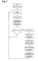
- Fig.2 depicts the basic algorithm for the detection of power system oscillations which is explained in a strongly simplified way below. A full account on the mathematical details can be found in the article " Detection of Oscillations in Power Systems using Kalman Filtering Techniques", P. Korba, M. Larsson, C. Rehtanz, IEEE (June 2003 ).
- all parameters used for recursive calculations must be initialized and the dynamical order (n) of the discrete-time autoregressive model (where n stands for the number of parameters to be estimated) must be determined.
- the latter task can be systematically solved off-line in advance based on a given set of real measured data using well-known criteria such as AIC (Akake's Information Criterion), FPE (Final Prediction Error) or MDL (minimal description length).
- AIC Alkake's Information Criterion
- FPE Frinal Prediction Error
- MDL minimal description length
- n is the most important aspect of the use of the autoregressive model. If the order is too low, the obtained spectrum in the frequency domain will be highly smoothed, and the oscillation of interest with low-level peaks in the spectrum are dissimulated. On the other hand, if the order is too high, faked low-level peaks will be introduced in the spectrum.
- Sampling a new measurement stands for storing the new measured data in a buffer having only the length n.
- the next step of the algorithm consists of solving recursively the optimal identification problem of the model parameters a i by means of the adaptive Kalman-Filter.
- the most suitable conversion of the estimated linear discrete-time autoregressive model of the power system to a continuous-time model is Tustin's approximation.
- This choice has the advantage that the left half-s-plane (s being the time continuous variable) is transferred into the unit-disc in z-plane (z being the time discrete variable of the time discrete model).
- the most important oscillations to detect regarding stability are the dominant ones. They are characterized by complex eigenvalues having the largest real part of all. Hence, in this step, the dominant eigenvalue pair is searched for in the set of all n eigenvalues calculated in the previous step.
- a negative or very small positive damping indicates that the system is (getting) unstable. This fact together with the corresponding values of frequency and damping are displayed to the operator.
- a simple signalization based on a comparison of the actual calculated value with a threshold value can be included.
- modal analysis was applied to identify a suitable system quantity corresponding to a signal of the phase angle of the current at a particular location.
- Fig.3 shows, as a function of time, the damping (top) and frequency (bottom) of a system oscillation. Every 100 sec, a transmission line was connected or disconnected, giving rise to a change in the oscillation pattern. Horizontal lines represent an alarm threshold 30 and are connected to some alarm mechanism.
- the incoming measured signal may temporarily consist of noise with a mean value close to zero rather than of realistic data. It is then advantageous to consider all measurements to equal exactly zero, otherwise the dominant frequency of the noise is estimated rather than the dominant frequency of the measured signal. Based on an observation of the average signal power, a threshold is fixed, and the estimated parameters will be frozen (not up-dated) if the actual signal power is lower than the threshold.
- the detection of electromechanical oscillations in power systems and the estimation of their parameters is based on a linear time-varying model.
- the parameters of the linear model are on-line adapted by means of Kalman filtering techniques to approximate the measured signal y (representing the behaviour of the power system) optimally in the sense of a quadratic criterion.
- the estimated model parameters are then the basis for the calculation of parameters of the oscillations.
- Adaptive algorithms are based on a recursive calculation of the estimated parameter vector for each time-step based on the new value of the measured signal and the old values of the estimated parameters.
Landscapes
- Engineering & Computer Science (AREA)
- Power Engineering (AREA)
- Supply And Distribution Of Alternating Current (AREA)
- Measurement Of Mechanical Vibrations Or Ultrasonic Waves (AREA)
- Air Bags (AREA)
Abstract
Description
- The invention relates to the field of electric power transmission networks interconnecting a plurality of generators. It departs from a method for detecting electromechanical oscillations in power systems as described in the preamble of
claim 1. - In the wake of the recent and still ongoing deregulations of the electric power markets, load transmission and wheeling of power from distant generators to local load consumers has become common practice. As a consequence of the competition between utilities and the emerging need to optimize assets, substantially increased amounts of power are transmitted through the existing networks, invariably causing transmission bottlenecks and oscillations of parts of the power transmission systems.
- Interconnected alternating current generators remain in synchronism because of the self-regulating properties of their interconnection. Hence, if a first generator deviates from its synchronous speed, power is transferred from the other generators in the system in such a way that the speed deviation is reduced. Since moments of inertia of the generators also come into play, this results typically in speed over-corrections and the whole system or a part thereof starts swinging in the same manner as a set of interconnected pendulums. In general, these electromagnetic oscillations with a frequency of less than a few Hz are stable and considered acceptable as long as they decay. They are initiated by the normal small changes in the system load, and they are a characteristic of any power system. However, an increase in the transmitted power of a few MWs may make the difference between stable oscillations and unstable oscillations which have the potential to cause a system collapse or result in lost of synchronism, lost of interconnections and ultimately the inability to supply electric power to the customer.
- An operator can control the power that the generators should supply under normal operating conditions and automatic control mechanisms are responsible for fast adjustments which are necessary to maintain the system voltages and line frequency (e.g. 50 Hz) within design limits following sudden changes in the system. These controls are necessary for any interconnected power system to supply power of the required quality. However there is no warning to the transmission operator if a new operating condition causes the abovementioned oscillatory modes to become lightly damped and thus potentially dangerous. Appropriate monitoring of the power system can help the operator to accurately assess power system states and avoid a total blackout by taking appropriate actions such as the connection of specially designed damping equipment.
- In the article "Estimation of Electro-Mechanical Parameters using Frequency Measurements" by M. Hemmingsson, O. Samuelsson, K.O.H. Pedersen and A.H. Nielsen, IEEE 2001, 0-7803-6672-7 (p. 1172) information about electro-mechanical mode parameters such as oscillation frequency and damping have been extracted from measurements made at a 230V wall-outlet during normal operation of the power system. Batches of measurements of the line frequency were taken, each lasting for a time window of at least 10 min, and subsequently analyzed. Spectral analysis of the instantaneous frequency revealed two well known electro-mechanical modes oscillating at 0.35 Hz and 0.57 Hz. A pole estimation procedure based on a stationary, time discrete model driven by white noise allowed to approximate the corresponding damping of the two modes. Due to the batch sampling technique, no on-line or real-time analysis of the power system was possible.
- Electric power transmission and distribution systems or networks comprise high-voltage tie lines for connecting geographically separated regions, medium-voltage lines, and substations for transforming voltages and for switching connections between lines. For managing the network, time-stamped local information about the network, in particular currents, voltages and load flows, can be provided by newly installed Phasor Measurement Units (PMU), c.f. the article "PMUs - A new approach to power network monitoring", ABB Review 1/2001, p. 58. A plurality of phasor measurements collected from throughout the network at a central data processor in combination provide a snapshot of the overall electrical state of the power system.
- The patent
US 6 476 521 discloses a system protection scheme based on measurements of time-stamped signals in at least two locations of the power system that are evaluated in view of poorly damped power oscillations. Direct measurement of a node angle difference between the at least two points in a power system provides an improved picture of the rotor angle oscillations compared to indirect local measurements evaluated in the case of conventional Power System Stabilizers (PSS). - It is therefore an objective of the invention to enable an operator of an electric power transmission network to identify in real-time electromechanical oscillations. This objective is achieved by a method, system and computer program for detecting electromechanical oscillations in power systems according to
claims - According to the invention, a system quantity or signal such as e.g. amplitude or angle of the voltage or current at a selected node of the network is sampled, i.e. measured at discrete time intervals, and a series comprising several of the measured values of said system quantity is generated. From this series, the parameters of a parametric model representing the behaviour of a power transmission system, or a particular aspect thereof, are estimated. This process is carried out in an adaptive manner, i.e. every time a new value of the system quantity is measured, the parameters of the model are updated recursively. Finally, from the estimated parameters of the model, the parameters of the oscillatory modes are computed, and in particular, their oscillation frequency and damping properties are quantified. The inventive process enables an almost instantaneous analysis of the state of the power system as compared to a non-adaptive identification process relying on the analysis of sampled data collected over a time-window of several minutes and evaluated only at the end of this time-window.
- In a preferred variant of the proposed approach, the parameters of the parametric model which fit best the measured values of the system quantity are estimated subject to an optimization criterion. Further, the model is assumed to predict the next sampled value of the system quantity, based on a time series containing a linear combination of a finite number of n previous measured values. Such a model is called linear autoregressive, with the integer n denoting its dynamical order as well as the number of parameters to be estimated. It has the advantage of the simple form of a linear difference equation containing only n parameters and additionally is suitable to represent frequency spectra with narrow peaks.
- According to a preferred variant of the invention, recursive or adaptive techniques such as recursive least square (RLS) or adaptive Kalman filtering are used to determine the parameters of the parametric model. The standard adaptive Kalman filtering algorithm can be advantageously enhanced by enforcing symmetry of the covariance or correlation matrix of the estimation error, thus increasing numerical robustness of the procedure.
- To obtain the parameters of the oscillations, the discrete-time linear autoregressive model is preferably converted to its continuous-time form. This may be done using some known transformation techniques and providing a known and constant sampling period. Tustin's bilinear transformation has proven to be the most suitable transformation technique for the abovementioned conversion. The reason for this resides in the fact that it converts the unit circle in the z-plane into the left half of the s-plane. Hence, stable discrete-time systems are transferred into stable continuous-time systems, of which the eigenvalues, i.e. the solutions of the characteristic equation (or poles if considering the transfer function) form the basis for a calculation of the studied oscillations. In other words, the parameters of the continuous-time model yield directly the desired information about the oscillations.
- In a preferred embodiment of the invention, the mode information about a critical oscillation, which is typically the dominant oscillatory mode having the lowest damping, is updated on a suitable time scale (which may be longer than the actual sampling rate) and presented to the operator. Optionally, the updated damping factor is compared to threshold values representing save or hazardous operation regimes, and the operator adjusts the transmitted power and thus optimally exploits the transmission resources.
- The observability of even the dominant oscillatory modes depends on the location or node of the network. Therefore, if a nominal model of the power system is available, modal analysis can be carried out to select optimally the best system quantity or signal to measure (or to place the phasor measurement unit) with respect to the observability of the oscillatory mode of interest.
- Instead of an on-line estimation of oscillation mode parameters as set forth above, a set of measured or simulated values of the system quantity may serve to compare different model systems. Such an off-line process may lead to the identification of suitable model systems and/or system variables like the order n or number of parameters in the abovementioned AR model and thus contribute to the synthesis of future controllers.
- The subject matter of the invention will be explained in more detail in the following text with reference to preferred exemplary embodiments which are illustrated in the attached drawings, of which:
- Fig.1 schematically shows a power system and wide area monitoring system,
- Fig.2 is a flowchart according to the inventive process, and
- Fig.3 depicts the real-time dependence of a dominant oscillation mode.
- The reference symbols used in the drawings, and their meanings, are listed in summary form in the list of reference symbols. In principle, identical parts are provided with the same reference symbols in the figures.
- Fig.1 shows an overview of a
power system 1 including twogenerators 10 as well as a wide area monitoring system. The latter comprises three phase measurement units (PMUs) 20 residing, for example, at a feeder at the bay level of substations or at branching points along transmission lines of the power system. The PMUs provide fast sampled phasor snapshots of the power system in the form of magnitudes, phase angles or even phase angle differences of system quantities yi such as voltages or currents. Correspondingly, the phasor data may be a complex or polar number, the absolute value of which corresponds to either the real magnitude or the RMS value of the system quantity, and the phase argument to the phase angle at zero time. By contrast, conventional sensing devices used in power networks generally measure only scalar, average representations, such as the RMS value of a voltage, current or power flow. The signals are transmitted and collected centrally in a wide-area monitoring centre 21. - If the phasor data from disparate sources, often separated by hundreds of kilometres, are analysed in conjunction, they must refer to a common phase reference. Therefore, the different PMUs must have local clocks that are synchronised with each other to within a given precision. Such a synchronisation of is preferably achieved with a known time distribution system, for example the global positioning (GPS)
system 22. In a typical implementation, the phasor data is determined at least every 100 milliseconds, with a temporal resolution of preferably less than 1 millisecond. Each measurement is then associated with a time stamp derived from the synchronised local clock. - Fig.2 depicts the basic algorithm for the detection of power system oscillations which is explained in a strongly simplified way below. A full account on the mathematical details can be found in the article "Detection of Oscillations in Power Systems using Kalman Filtering Techniques", P. Korba, M. Larsson, C. Rehtanz, IEEE (June 2003). As a first step, all parameters used for recursive calculations must be initialized and the dynamical order (n) of the discrete-time autoregressive model (where n stands for the number of parameters to be estimated) must be determined. The latter task can be systematically solved off-line in advance based on a given set of real measured data using well-known criteria such as AIC (Akake's Information Criterion), FPE (Final Prediction Error) or MDL (minimal description length).
- The selection of the order n is the most important aspect of the use of the autoregressive model. If the order is too low, the obtained spectrum in the frequency domain will be highly smoothed, and the oscillation of interest with low-level peaks in the spectrum are dissimulated. On the other hand, if the order is too high, faked low-level peaks will be introduced in the spectrum.
- Sampling a new measurement stands for storing the new measured data in a buffer having only the length n. The next step of the algorithm consists of solving recursively the optimal identification problem of the model parameters ai by means of the adaptive Kalman-Filter. In the linear autoregressive model, the time series for the predicted value ŷ (as opposed to the measured value) of the system quantity y at measurement or iteration time k is written as

rewritten also as
where y(k-i) are the buffered samples, a(k) is the vector of the model parameters a(k)=[a1(k),..., an(k)] to be estimated at iteration time k, and ε(k) is the estimation error at step k. The latter is to be minimized via the sum of squared prediction errors as a function of the model parameters ai:
This is done recursively, taking further into account the correlation matrix K(k) of the estimation error, the Kalman gains g(k) and the correlation matrix of the measurement noise Qm or process noise Qp, wherein Qm and Qp represent rather insensitive tuning parameters. For the sake of numerical robustness, the above standard adaptive filtering algorithm can be enhanced by adding the following step:
This equation enforces the symmetry of the matrix K at each iteration step, which otherwise is not automatically guaranteed anywhere in the recursive procedure above. - Unlike the recursive equations of the Kalman-Filter, where the estimates are updated as soon as new measured data are available, all the remaining steps need to be carried out only once per "Refresh_Time" period. The latter is specified in advance or during operation according to the actual slowness/fastness of the time-varying system (e.g. every 5 sec instead of once per sampling period which is typically 0.1 sec) to calculate and display the parameters of the oscillations (damping and frequency) out of the estimated model parameters.
- For the purpose of calculating the damping and frequency of the dominant oscillations, the most suitable conversion of the estimated linear discrete-time autoregressive model of the power system to a continuous-time model is Tustin's approximation. This choice has the advantage that the left half-s-plane (s being the time continuous variable) is transferred into the unit-disc in z-plane (z being the time discrete variable of the time discrete model). Hence, stable discrete-time systems are transferred into stable continuous-time systems whose eigenvalues λi (or poles if considering the transfer function) are obtained as a solution of the characteristic equation of the continuous-time model A(s)=0 and form the basis for calculation of the studied oscillations.
- The most important oscillations to detect regarding stability are the dominant ones. They are characterized by complex eigenvalues having the largest real part of all. Hence, in this step, the dominant eigenvalue pair is searched for in the set of all n eigenvalues calculated in the previous step. Finally, in the last step, the parameters characterizing quantitatively the oscillations of interest, such as frequency f and relative damping ξ, are simply calculated from the complex dominant eigenvalue pair λi = αi ± i ωi as follows:


In a normally working power system (stable dynamic system) they usually satisfy the following inequalities.
- The detection of a negative or very small positive damping indicates that the system is (getting) unstable. This fact together with the corresponding values of frequency and damping are displayed to the operator. A simple signalization based on a comparison of the actual calculated value with a threshold value can be included. By way of example, based on reduced nominal model of a real power system, modal analysis was applied to identify a suitable system quantity corresponding to a signal of the phase angle of the current at a particular location. Fig.3 shows, as a function of time, the damping (top) and frequency (bottom) of a system oscillation. Every 100 sec, a transmission line was connected or disconnected, giving rise to a change in the oscillation pattern. Horizontal lines represent an
alarm threshold 30 and are connected to some alarm mechanism. - In case of low signal to noise ratio, e.g. in case of a sensor fault, the incoming measured signal may temporarily consist of noise with a mean value close to zero rather than of realistic data. It is then advantageous to consider all measurements to equal exactly zero, otherwise the dominant frequency of the noise is estimated rather than the dominant frequency of the measured signal. Based on an observation of the average signal power, a threshold is fixed, and the estimated parameters will be frozen (not up-dated) if the actual signal power is lower than the threshold.
- To identify oscillations in a power system, different physical signals can be used (voltages, currents, amplitudes, angles) as inputs to the proposed identification procedure. However, these signals differ with respect to their magnitudes and herewith also with respect to the signal power, signal-to-noise ratio, absolute values of the autocorrelation etc. Therefore, for the sake of simplicity with respect to tuning of parameters in the estimation procedure for different measured signals, each measurement can be multiplied by an amplifying constant depending on the system quantity or signal before putting into an input buffer. This simple normalization does not improve the quality of the measured signal, but it renders the tuning (finding the right parameters for initialization) of the identification algorithm easier when working with different signals in the same power system.
- In summary, the detection of electromechanical oscillations in power systems and the estimation of their parameters (frequency f and damping ξ) is based on a linear time-varying model. The parameters of the linear model are on-line adapted by means of Kalman filtering techniques to approximate the measured signal y (representing the behaviour of the power system) optimally in the sense of a quadratic criterion. The estimated model parameters are then the basis for the calculation of parameters of the oscillations. Adaptive algorithms are based on a recursive calculation of the estimated parameter vector for each time-step based on the new value of the measured signal and the old values of the estimated parameters. As opposed to the collection of data over a time window and then performing the parameter identification at once, any change in the system can thus be detected much faster.
-
- 1
- power system
- 10
- generator
- 20
- phase measurement units
- 21
- wide-area monitoring centre
- 22
- global positioning system
- 30
- alarm threshold
Claims (10)
- Method of detecting electromechanical oscillations in a power system (1), whereina) a dynamic system quantity (y) of the power system (1) is repeatedly measured and a series of measured values (y1, y2, ...) of the dynamic system quantity (y) is generated,b) model parameters (a1, a2, ...) of afinite-order discrete-time model of the power system (1) are estimated from said series (y1, y2,...),c) frequency and damping (ν, ξ) of an electromechanical oscillation mode of the power system (1) are deduced from said model parameters (a1, a2, ...),
characterized in thatd) said model parameters (a1, a2, ...) are updated recursively every time a new value (yk) of the dynamic system quantity (y) is measured. - The method according to claim 1, characterized in that the finite order discrete-time model of the power system is a linear autoregressive model of finite order.
- The method according to claim 2, characterized in that an adaptive Kalman Filter is used to estimate the model parameters (a1, a2,..) of the linear autoregressive model.
- The method according to claim 3, characterized in that a covariance matrix K(k) of the adaptive Kalman Filter is symmetrical.
- The method according to claim 2, characterized in that a bilinear or Tustin transformation is used to convert the discrete-time linear autoregressive model to a continuous-time model.
- The method according to one of claims 1 to 5, characterized in that frequency and damping (ν, ξ) of the oscillation mode with lowest damping is updated regularly and displayed to an operator.
- The method according to claim 1, characterized in that the frequency and damping (v, ξ) of the oscillations are deduced from the model parameters (a1, a2,..) less frequently than the model parameters (a1, a2,..) are updated.
- The method according to one of the preceding claims, characterized in that the dynamic system quantity (y) is a time stamped phasor signal provided by one phasor measurement unit (20).
- An electric power transmission system (1) including means for detecting electromechanical oscillations of the power system (1), comprisinga) means (20) for repeatedly measuring a dynamic_system quantity (y) of the power system (1) and generating a series of measured values (y1, y2, ...) of the dynamic_system quantity (y),b) means for estimating, from said series (y1, y2, ...), model parameters (a1, a2, ...) of a finite-order discrete-time model of the power system (1),c) means for deducing, from said model parameters (a1, a2, ...), frequency and damping (v, ξ) of an electromechanical oscillation mode of the power system (1),
characterized in that the means for detecting electromechanical oscillations of the power system (1) comprised) means for updating recursively said model parameters (a1, a2, ...) every time a new value (yk) of the dynamic system quantity (y) is measured. - A computer program product for detecting electromechanical oscillations in electric power transmission systems which is loadable into an internal memory of a digital computer, comprising computer program code means to make, when said program is loaded in said internal memory, the computer execute the method for detecting electromechanical oscillations according to one of claims 1 to 8.
Priority Applications (6)
| Application Number | Priority Date | Filing Date | Title |
|---|---|---|---|
| EP03405450A EP1489714B1 (en) | 2003-06-21 | 2003-06-21 | Detecting electromechanical oscillations in power systems |
| DE60318408T DE60318408T2 (en) | 2003-06-21 | 2003-06-21 | Determination of electromechanical vibrations in power supply systems |
| ES03405450T ES2299678T3 (en) | 2003-06-21 | 2003-06-21 | METHOD FOR DETECTING ELECTROMECHANICAL SWINGS IN POWER SYSTEM. |
| AT03405450T ATE382975T1 (en) | 2003-06-21 | 2003-06-21 | DETERMINATION OF ELECTROMECHANICAL VIBRATIONS IN POWER SUPPLY SYSTEMS |
| SI200331168T SI1489714T1 (en) | 2003-06-21 | 2003-06-21 | Detection of electromechanical oscillations in power systems |
| US10/871,685 US7149637B2 (en) | 2003-06-21 | 2004-06-18 | Detecting electromechanical oscillations in power systems |
Applications Claiming Priority (1)
| Application Number | Priority Date | Filing Date | Title |
|---|---|---|---|
| EP03405450A EP1489714B1 (en) | 2003-06-21 | 2003-06-21 | Detecting electromechanical oscillations in power systems |
Publications (2)
| Publication Number | Publication Date |
|---|---|
| EP1489714A1 EP1489714A1 (en) | 2004-12-22 |
| EP1489714B1 true EP1489714B1 (en) | 2008-01-02 |
Family
ID=33396095
Family Applications (1)
| Application Number | Title | Priority Date | Filing Date |
|---|---|---|---|
| EP03405450A Expired - Lifetime EP1489714B1 (en) | 2003-06-21 | 2003-06-21 | Detecting electromechanical oscillations in power systems |
Country Status (6)
| Country | Link |
|---|---|
| US (1) | US7149637B2 (en) |
| EP (1) | EP1489714B1 (en) |
| AT (1) | ATE382975T1 (en) |
| DE (1) | DE60318408T2 (en) |
| ES (1) | ES2299678T3 (en) |
| SI (1) | SI1489714T1 (en) |
Cited By (1)
| Publication number | Priority date | Publication date | Assignee | Title |
|---|---|---|---|---|
| WO2013087122A1 (en) | 2011-12-16 | 2013-06-20 | Siemens Aktiengesellschaft | Method for generating a signal indicating an oscillation in an electrical energy supply network |
Families Citing this family (54)
| Publication number | Priority date | Publication date | Assignee | Title |
|---|---|---|---|---|
| US7233843B2 (en) * | 2003-08-08 | 2007-06-19 | Electric Power Group, Llc | Real-time performance monitoring and management system |
| EP1737098A1 (en) | 2005-06-24 | 2006-12-27 | Abb Research Ltd. | Damping electromagnetic oscillations in power system |
| EP1780619A1 (en) * | 2005-10-31 | 2007-05-02 | Abb Research Ltd. | Initializing an estimation of dynamic model parameters |
| EP1783499A1 (en) * | 2005-11-08 | 2007-05-09 | ABB Technology AG | Method and apparatus for verifying the accuracy of state estimation calculations |
| ES2333381T3 (en) * | 2006-05-19 | 2010-02-19 | Abb Research Ltd. | DETECTION OF FAILURES IN ENERGY SYSTEMS. |
| EP1887673A1 (en) * | 2006-08-11 | 2008-02-13 | Abb Research Ltd. | Parameter estimation of a thermal model of a power line |
| US7494271B2 (en) * | 2007-02-05 | 2009-02-24 | Abb Research Ltd. | Power-line sag calculation by way of power-system state estimation |
| US9702923B2 (en) | 2007-09-17 | 2017-07-11 | Pål Even Gaarder | Method and apparatus for monitoring electric power transmission, disturbances and forecasts |
| WO2009037163A2 (en) * | 2007-09-17 | 2009-03-26 | Ably As | Method and apparatus for monitoring power transmission |
| US8498832B2 (en) * | 2007-09-28 | 2013-07-30 | Schweitzer Engineering Laboratories Inc. | Method and device for assessing and monitoring voltage security in a power system |
| US7987059B2 (en) * | 2007-10-09 | 2011-07-26 | Schweitzer Engineering Laboratories, Inc | Real-time power system oscillation detection using modal analysis |
| US8892375B2 (en) | 2008-05-09 | 2014-11-18 | Accenture Global Services Limited | Power grid outage and fault condition management |
| US7979220B2 (en) * | 2008-08-21 | 2011-07-12 | Abb Research Ltd. | System and method for monitoring power damping compliance of a power generation unit |
| CN101685966B (en) * | 2008-09-27 | 2012-07-04 | 国家电力调度通信中心 | Method for comprehensively analyzing low-frequency oscillation and system thereof |
| CA2972362C (en) * | 2008-12-15 | 2019-08-13 | Accenture Global Services Limited | Power grid outage and fault condition management |
| CN101661069B (en) * | 2009-09-25 | 2011-07-20 | 北京四方继保自动化股份有限公司 | Dynamic process real-time estimation method of weak observable non-PMU measuring point independent of state matrix |
| EP2312506A1 (en) | 2009-10-16 | 2011-04-20 | ABB Technology AG | Computer-based method and device for automatically providing a prediction on a future energy demand to an energy source |
| WO2011050827A1 (en) * | 2009-10-29 | 2011-05-05 | Siemens Aktiengesellschaft | Monitoring of an energy transmission system or energy distribution system |
| EP2325968A1 (en) | 2009-11-18 | 2011-05-25 | ABB Research Ltd. | Tuning a power oscillation damping unit |
| CN102870308B (en) | 2010-03-17 | 2016-01-20 | Abb研究有限公司 | Strengthen the wide-area control reliability of transmission system |
| CN102055201B (en) * | 2010-12-09 | 2012-11-14 | 北京四方继保自动化股份有限公司 | Power system low-frequency oscillation mechanism analysis method based on micro-disturbance signal oscillation mode recognition |
| US9350163B2 (en) | 2011-10-19 | 2016-05-24 | General Electric Company | Inter-area oscillation detection |
| US9293949B2 (en) | 2012-02-06 | 2016-03-22 | Montana Tech Of The University Of Montana | Electric power grid signal processing methods, oscillatory mode estimation methods and mode shape estimation methods |
| RU2521768C2 (en) * | 2012-07-20 | 2014-07-10 | Открытое Акционерное Общество "Системный Оператор Единой Энергетической Системы" | Method for determination of synchronous oscillations source |
| EP2713172B1 (en) | 2012-09-26 | 2019-05-29 | Rheinisch-Westfälisch-Technische Hochschule Aachen | Measurement apparatus for electricity distribution grids |
| CN102930077B (en) * | 2012-09-27 | 2014-10-29 | 华北电力大学 | Error-resistant excitation system parameter identification method based on improved target function |
| US9864820B2 (en) * | 2012-10-03 | 2018-01-09 | Operation Technology, Inc. | Generator dynamic model parameter estimation and tuning using online data and subspace state space model |
| CN102928695A (en) * | 2012-10-18 | 2013-02-13 | 中国电力科学研究院 | Method for judging negatively-damped oscillation and forced oscillation on basis of straight line method |
| RU2513874C1 (en) * | 2012-11-02 | 2014-04-20 | Открытое Акционерное Общество "Системный Оператор Единой Энергетической Системы" | Method for monitoring of transient modes in electric energy system and device for its implementation |
| CA2898655A1 (en) | 2013-02-14 | 2014-08-21 | Schweitzer Engineering Laboratories, Inc. | Detection of poorly damped oscillation modes |
| CN103473401B (en) * | 2013-08-29 | 2016-09-21 | 国家电网公司 | Wind turbine model based on PSASP and power disturbance realistically displayed method thereof |
| CN103530816A (en) * | 2013-10-10 | 2014-01-22 | 国家电网公司 | Power supply reliability-oriented secondary optimization evaluation model for reliability of power distribution network |
| CN103646146B (en) * | 2013-12-20 | 2017-03-29 | 武汉大学 | Based on the SVC controller method for designing for improving Atomic Decomposition parameter identification |
| EP2891904A1 (en) | 2014-01-07 | 2015-07-08 | ABB Technology AB | Solar irradiance forecasting |
| US9590550B2 (en) | 2014-01-16 | 2017-03-07 | General Electric Company | Systems and methods for adaptive control of excitation and generator systems |
| EP2978095A1 (en) | 2014-07-23 | 2016-01-27 | ABB Technology AG | Power system operation |
| CN104898415B (en) * | 2015-03-31 | 2017-09-19 | 北京四方继保自动化股份有限公司 | A kind of on-line identification method of the generating set rotary inertia parameter based on LPF |
| CN105140957B (en) * | 2015-08-20 | 2017-10-10 | 华北电力大学 | Electromechanic oscillation mode evaluation method based on wind power plant and photovoltaic plant polymerization model |
| CN105866633B (en) * | 2016-05-30 | 2018-06-19 | 上海交通大学 | The replay method of transmission line malfunction current traveling wave waveform based on wave weight |
| PL3252482T3 (en) * | 2016-06-01 | 2021-08-02 | Siemens Aktiengesellschaft | Method and device of a control center for determining the phase angle of power oscillation in an electric power supply network |
| CN106169115B (en) * | 2016-06-23 | 2020-04-14 | 西南交通大学 | A method for estimating the lowest frequency of power grids in two regions by analytical-numerical method |
| CN108090270B (en) * | 2017-12-12 | 2020-12-22 | 华南理工大学 | A Transient Oscillation Parameter Identification Method Based on Morphological Filtering and Blind Source Separation |
| CN108462192B (en) * | 2018-04-28 | 2020-05-05 | 清华大学 | Mode analysis method for broadband oscillation of power system |
| JP7034978B2 (en) * | 2019-03-19 | 2022-03-14 | 株式会社東芝 | System stabilizer |
| CN110323741B (en) * | 2019-07-10 | 2022-05-13 | 国网福建省电力有限公司 | Low-frequency oscillation analysis and suppression method for power system based on wave recording curve |
| CN110728177B (en) * | 2019-09-02 | 2022-06-14 | 华南理工大学 | Noise-like data low-frequency oscillation identification method based on double covariance random subspace |
| CN112531736B (en) * | 2020-11-24 | 2023-10-31 | 国家电网有限公司 | A wide-area damping controller design method for inter-regional oscillation suppression in power systems |
| CN112366735B (en) * | 2020-12-01 | 2022-06-07 | 合肥工业大学 | Micro-grid secondary frequency modulation method based on self-adaptive online model identification |
| CN113156200B (en) * | 2020-12-14 | 2023-01-13 | 北京信息科技大学 | Power grid low-frequency oscillation real-time monitoring device |
| CN114123238B (en) * | 2021-11-12 | 2023-09-22 | 国网江苏省电力有限公司营销服务中心 | A Kalman filter control method for electrolytic aluminum load to participate in power system frequency regulation |
| CN114301077A (en) * | 2021-12-29 | 2022-04-08 | 国家电网公司西南分部 | Power system negative weak damping unit identification method and system |
| CN115378122B (en) * | 2022-04-11 | 2023-05-09 | 东南大学溧阳研究院 | Power system frequency and inertia real-time monitoring method and system based on Kalman filter |
| CN115357853B (en) * | 2022-08-22 | 2023-08-04 | 河海大学 | A Method for Identification of Modal Parameters of Engineering Structures Based on Fast Random Subspace |
| FR3141573A1 (en) | 2022-10-26 | 2024-05-03 | General Electric Company | SYSTEMS AND METHODS FOR AN ADAPTIVE ELECTRICAL SYSTEM STABILIZER (PSS) |
Family Cites Families (9)
| Publication number | Priority date | Publication date | Assignee | Title |
|---|---|---|---|---|
| US4051427A (en) * | 1974-10-29 | 1977-09-27 | Westinghouse Electric Corporation | Supervisory system for detecting torsional oscillation in the shaft of a rotating electro-mechanical system |
| US4741023A (en) * | 1986-12-23 | 1988-04-26 | General Electric Company | On-line test and diagnostic system for power system stabilizer |
| US5566092A (en) * | 1993-12-30 | 1996-10-15 | Caterpillar Inc. | Machine fault diagnostics system and method |
| DE19746719C1 (en) * | 1997-10-15 | 1999-05-06 | Siemens Ag | Power swing indication signal determination method e.g. for power supply network |
| DE19927524A1 (en) * | 1998-06-17 | 1999-12-23 | Siemens Ag | Model based design method for pendulum damping device for turbogenerators in gas and/or steam power stations |
| DE19948694B4 (en) * | 1999-09-30 | 2006-04-06 | Siemens Ag | A method of generating a signal indicative of a swing in an electrical power supply network |
| SE517714C2 (en) * | 2000-05-31 | 2002-07-09 | Abb Ab | Mains protection system for protecting the integrity of a total electrical power system against slightly damped power fluctuations, electric power system including a network protection, system protection system procedure, system protection terminal, computer program product and computer readable medium |
| DE60221668T2 (en) * | 2001-06-22 | 2008-05-21 | Psymetrix Ltd. | METHOD FOR MONITORING A HIGH VOLTAGE NETWORK |
| US20040102937A1 (en) * | 2002-11-21 | 2004-05-27 | Honeywell International Inc. | Energy forecasting using model parameter estimation |
-
2003
- 2003-06-21 DE DE60318408T patent/DE60318408T2/en not_active Expired - Lifetime
- 2003-06-21 EP EP03405450A patent/EP1489714B1/en not_active Expired - Lifetime
- 2003-06-21 SI SI200331168T patent/SI1489714T1/en unknown
- 2003-06-21 ES ES03405450T patent/ES2299678T3/en not_active Expired - Lifetime
- 2003-06-21 AT AT03405450T patent/ATE382975T1/en not_active IP Right Cessation
-
2004
- 2004-06-18 US US10/871,685 patent/US7149637B2/en not_active Expired - Lifetime
Cited By (1)
| Publication number | Priority date | Publication date | Assignee | Title |
|---|---|---|---|---|
| WO2013087122A1 (en) | 2011-12-16 | 2013-06-20 | Siemens Aktiengesellschaft | Method for generating a signal indicating an oscillation in an electrical energy supply network |
Also Published As
| Publication number | Publication date |
|---|---|
| US7149637B2 (en) | 2006-12-12 |
| EP1489714A1 (en) | 2004-12-22 |
| ES2299678T3 (en) | 2008-06-01 |
| ATE382975T1 (en) | 2008-01-15 |
| DE60318408T2 (en) | 2009-01-29 |
| SI1489714T1 (en) | 2008-06-30 |
| US20050187726A1 (en) | 2005-08-25 |
| DE60318408D1 (en) | 2008-02-14 |
Similar Documents
| Publication | Publication Date | Title |
|---|---|---|
| EP1489714B1 (en) | Detecting electromechanical oscillations in power systems | |
| Korba et al. | Detection of oscillations in power systems using Kalman filtering techniques | |
| RU2430457C2 (en) | Estimating parameters of electric power supply line thermal model | |
| US9746511B2 (en) | Estimating the locations of power system events using PMU measurements | |
| Korba | Real-time monitoring of electromechanical oscillations in power systems: first findings | |
| EP0873583B1 (en) | Digital current differential system | |
| US8340931B2 (en) | Power grid with comparison of differences in remote phasor changes | |
| EP2018694B1 (en) | Detecting faults in power systems | |
| EP2962376B1 (en) | Oscillation analysis method and apparatus therefor | |
| US20050141682A1 (en) | Power grid failure detection system and method | |
| JP2003052126A (en) | Power network stability prediction | |
| US20150168465A1 (en) | Method and apparatus for electric power system distribution state estimations | |
| WO2012060883A2 (en) | Power grid failure prediction and detection | |
| US8373309B2 (en) | Systems and methods for asynchronous sampling data conversion | |
| EP4429059A1 (en) | Processing method and processing system for processing measurements acquired in a power grid, and system comprising a power grid | |
| US10371592B2 (en) | System stability monitoring apparatus and method | |
| WO2019086946A1 (en) | System and method for analyzing fault data of a power transmission network | |
| CN120294800A (en) | A traveling wave fault location system and method based on Beidou synchronization and intelligent filtering | |
| EP2795759B1 (en) | Handling resonances in a power transmission system | |
| KR101664010B1 (en) | An Estimation Method of Line Parameter based on Synchrophasor Measurements in Power System | |
| Yu et al. | Unscented trainable Kalman filter based on deep learning method considering incomplete information | |
| Khond et al. | Detection of bad data and estimation of missing parameter values using system synergism | |
| Ghasemi et al. | Confidence intervals estimation in the identification of electromechanical modes from ambient noise | |
| Moreno-Chuquen et al. | Online dynamic assessment of system stability in power systems using the unscented kalman filter | |
| Mahmoud et al. | Out‐of‐step detection of synchronous generators using dual computational techniques based on correlation and instantaneous powers |
Legal Events
| Date | Code | Title | Description |
|---|---|---|---|
| PUAI | Public reference made under article 153(3) epc to a published international application that has entered the european phase |
Free format text: ORIGINAL CODE: 0009012 |
|
| AK | Designated contracting states |
Kind code of ref document: A1 Designated state(s): AT BE BG CH CY CZ DE DK EE ES FI FR GB GR HU IE IT LI LU MC NL PT RO SE SI SK TR |
|
| AX | Request for extension of the european patent |
Extension state: AL LT LV MK |
|
| 17P | Request for examination filed |
Effective date: 20050509 |
|
| 17Q | First examination report despatched |
Effective date: 20050629 |
|
| AKX | Designation fees paid |
Designated state(s): AT BE BG CH CY CZ DE DK EE ES FI FR GB GR HU IE IT LI LU MC NL PT RO SE SI SK TR |
|
| 17Q | First examination report despatched |
Effective date: 20050629 |
|
| GRAP | Despatch of communication of intention to grant a patent |
Free format text: ORIGINAL CODE: EPIDOSNIGR1 |
|
| GRAS | Grant fee paid |
Free format text: ORIGINAL CODE: EPIDOSNIGR3 |
|
| GRAA | (expected) grant |
Free format text: ORIGINAL CODE: 0009210 |
|
| AK | Designated contracting states |
Kind code of ref document: B1 Designated state(s): AT BE BG CH CY CZ DE DK EE ES FI FR GB GR HU IE IT LI LU MC NL PT RO SE SI SK TR |
|
| REG | Reference to a national code |
Ref country code: GB Ref legal event code: FG4D |
|
| REG | Reference to a national code |
Ref country code: IE Ref legal event code: FG4D |
|
| REG | Reference to a national code |
Ref country code: CH Ref legal event code: EP |
|
| REF | Corresponds to: |
Ref document number: 60318408 Country of ref document: DE Date of ref document: 20080214 Kind code of ref document: P |
|
| REG | Reference to a national code |
Ref country code: RO Ref legal event code: EPE |
|
| REG | Reference to a national code |
Ref country code: SE Ref legal event code: TRGR |
|
| PG25 | Lapsed in a contracting state [announced via postgrant information from national office to epo] |
Ref country code: NL Free format text: LAPSE BECAUSE OF FAILURE TO SUBMIT A TRANSLATION OF THE DESCRIPTION OR TO PAY THE FEE WITHIN THE PRESCRIBED TIME-LIMIT Effective date: 20080102 |
|
| REG | Reference to a national code |
Ref country code: ES Ref legal event code: FG2A Ref document number: 2299678 Country of ref document: ES Kind code of ref document: T3 |
|
| NLV1 | Nl: lapsed or annulled due to failure to fulfill the requirements of art. 29p and 29m of the patents act | ||
| REG | Reference to a national code |
Ref country code: HU Ref legal event code: AG4A Ref document number: E003115 Country of ref document: HU |
|
| PG25 | Lapsed in a contracting state [announced via postgrant information from national office to epo] |
Ref country code: LI Free format text: LAPSE BECAUSE OF FAILURE TO SUBMIT A TRANSLATION OF THE DESCRIPTION OR TO PAY THE FEE WITHIN THE PRESCRIBED TIME-LIMIT Effective date: 20080102 Ref country code: FI Free format text: LAPSE BECAUSE OF FAILURE TO SUBMIT A TRANSLATION OF THE DESCRIPTION OR TO PAY THE FEE WITHIN THE PRESCRIBED TIME-LIMIT Effective date: 20080102 Ref country code: CH Free format text: LAPSE BECAUSE OF FAILURE TO SUBMIT A TRANSLATION OF THE DESCRIPTION OR TO PAY THE FEE WITHIN THE PRESCRIBED TIME-LIMIT Effective date: 20080102 |
|
| REG | Reference to a national code |
Ref country code: CH Ref legal event code: PL |
|
| PG25 | Lapsed in a contracting state [announced via postgrant information from national office to epo] |
Ref country code: AT Free format text: LAPSE BECAUSE OF FAILURE TO SUBMIT A TRANSLATION OF THE DESCRIPTION OR TO PAY THE FEE WITHIN THE PRESCRIBED TIME-LIMIT Effective date: 20080102 |
|
| PG25 | Lapsed in a contracting state [announced via postgrant information from national office to epo] |
Ref country code: BE Free format text: LAPSE BECAUSE OF FAILURE TO SUBMIT A TRANSLATION OF THE DESCRIPTION OR TO PAY THE FEE WITHIN THE PRESCRIBED TIME-LIMIT Effective date: 20080102 Ref country code: PT Free format text: LAPSE BECAUSE OF FAILURE TO SUBMIT A TRANSLATION OF THE DESCRIPTION OR TO PAY THE FEE WITHIN THE PRESCRIBED TIME-LIMIT Effective date: 20080602 |
|
| PG25 | Lapsed in a contracting state [announced via postgrant information from national office to epo] |
Ref country code: SK Free format text: LAPSE BECAUSE OF FAILURE TO SUBMIT A TRANSLATION OF THE DESCRIPTION OR TO PAY THE FEE WITHIN THE PRESCRIBED TIME-LIMIT Effective date: 20080102 Ref country code: DK Free format text: LAPSE BECAUSE OF FAILURE TO SUBMIT A TRANSLATION OF THE DESCRIPTION OR TO PAY THE FEE WITHIN THE PRESCRIBED TIME-LIMIT Effective date: 20080102 |
|
| PLBE | No opposition filed within time limit |
Free format text: ORIGINAL CODE: 0009261 |
|
| STAA | Information on the status of an ep patent application or granted ep patent |
Free format text: STATUS: NO OPPOSITION FILED WITHIN TIME LIMIT |
|
| 26N | No opposition filed |
Effective date: 20081003 |
|
| PG25 | Lapsed in a contracting state [announced via postgrant information from national office to epo] |
Ref country code: MC Free format text: LAPSE BECAUSE OF NON-PAYMENT OF DUE FEES Effective date: 20080630 |
|
| PG25 | Lapsed in a contracting state [announced via postgrant information from national office to epo] |
Ref country code: CY Free format text: LAPSE BECAUSE OF FAILURE TO SUBMIT A TRANSLATION OF THE DESCRIPTION OR TO PAY THE FEE WITHIN THE PRESCRIBED TIME-LIMIT Effective date: 20080102 |
|
| PG25 | Lapsed in a contracting state [announced via postgrant information from national office to epo] |
Ref country code: LU Free format text: LAPSE BECAUSE OF NON-PAYMENT OF DUE FEES Effective date: 20080621 |
|
| PG25 | Lapsed in a contracting state [announced via postgrant information from national office to epo] |
Ref country code: TR Free format text: LAPSE BECAUSE OF FAILURE TO SUBMIT A TRANSLATION OF THE DESCRIPTION OR TO PAY THE FEE WITHIN THE PRESCRIBED TIME-LIMIT Effective date: 20080102 |
|
| PG25 | Lapsed in a contracting state [announced via postgrant information from national office to epo] |
Ref country code: GR Free format text: LAPSE BECAUSE OF FAILURE TO SUBMIT A TRANSLATION OF THE DESCRIPTION OR TO PAY THE FEE WITHIN THE PRESCRIBED TIME-LIMIT Effective date: 20080403 |
|
| PGFP | Annual fee paid to national office [announced via postgrant information from national office to epo] |
Ref country code: ES Payment date: 20150626 Year of fee payment: 13 Ref country code: GB Payment date: 20150618 Year of fee payment: 13 Ref country code: EE Payment date: 20150611 Year of fee payment: 13 Ref country code: SE Payment date: 20150618 Year of fee payment: 13 Ref country code: BG Payment date: 20150611 Year of fee payment: 13 |
|
| PGFP | Annual fee paid to national office [announced via postgrant information from national office to epo] |
Ref country code: IT Payment date: 20150622 Year of fee payment: 13 Ref country code: HU Payment date: 20150618 Year of fee payment: 13 Ref country code: IE Payment date: 20150619 Year of fee payment: 13 |
|
| REG | Reference to a national code |
Ref country code: FR Ref legal event code: PLFP Year of fee payment: 14 |
|
| PGFP | Annual fee paid to national office [announced via postgrant information from national office to epo] |
Ref country code: CZ Payment date: 20160620 Year of fee payment: 14 |
|
| PGFP | Annual fee paid to national office [announced via postgrant information from national office to epo] |
Ref country code: SI Payment date: 20160525 Year of fee payment: 14 Ref country code: RO Payment date: 20160601 Year of fee payment: 14 |
|
| REG | Reference to a national code |
Ref country code: EE Ref legal event code: MM4A Ref document number: E002047 Country of ref document: EE Effective date: 20160630 |
|
| REG | Reference to a national code |
Ref country code: SE Ref legal event code: EUG |
|
| PG25 | Lapsed in a contracting state [announced via postgrant information from national office to epo] |
Ref country code: SE Free format text: LAPSE BECAUSE OF NON-PAYMENT OF DUE FEES Effective date: 20160622 |
|
| GBPC | Gb: european patent ceased through non-payment of renewal fee |
Effective date: 20160621 |
|
| REG | Reference to a national code |
Ref country code: IE Ref legal event code: MM4A |
|
| PG25 | Lapsed in a contracting state [announced via postgrant information from national office to epo] |
Ref country code: HU Free format text: LAPSE BECAUSE OF NON-PAYMENT OF DUE FEES Effective date: 20160622 Ref country code: EE Free format text: LAPSE BECAUSE OF NON-PAYMENT OF DUE FEES Effective date: 20160630 |
|
| PG25 | Lapsed in a contracting state [announced via postgrant information from national office to epo] |
Ref country code: BG Free format text: LAPSE BECAUSE OF NON-PAYMENT OF DUE FEES Effective date: 20170131 Ref country code: IE Free format text: LAPSE BECAUSE OF NON-PAYMENT OF DUE FEES Effective date: 20160621 Ref country code: GB Free format text: LAPSE BECAUSE OF NON-PAYMENT OF DUE FEES Effective date: 20160621 |
|
| REG | Reference to a national code |
Ref country code: FR Ref legal event code: PLFP Year of fee payment: 15 |
|
| PG25 | Lapsed in a contracting state [announced via postgrant information from national office to epo] |
Ref country code: IT Free format text: LAPSE BECAUSE OF NON-PAYMENT OF DUE FEES Effective date: 20160621 |
|
| PG25 | Lapsed in a contracting state [announced via postgrant information from national office to epo] |
Ref country code: RO Free format text: LAPSE BECAUSE OF NON-PAYMENT OF DUE FEES Effective date: 20170621 Ref country code: CZ Free format text: LAPSE BECAUSE OF NON-PAYMENT OF DUE FEES Effective date: 20170621 |
|
| REG | Reference to a national code |
Ref country code: SI Ref legal event code: KO00 Effective date: 20180213 |
|
| PG25 | Lapsed in a contracting state [announced via postgrant information from national office to epo] |
Ref country code: SI Free format text: LAPSE BECAUSE OF NON-PAYMENT OF DUE FEES Effective date: 20170622 Ref country code: ES Free format text: LAPSE BECAUSE OF NON-PAYMENT OF DUE FEES Effective date: 20160622 |
|
| REG | Reference to a national code |
Ref country code: FR Ref legal event code: PLFP Year of fee payment: 16 |
|
| REG | Reference to a national code |
Ref country code: ES Ref legal event code: FD2A Effective date: 20181203 |
|
| REG | Reference to a national code |
Ref country code: DE Ref legal event code: R081 Ref document number: 60318408 Country of ref document: DE Owner name: HITACHI ENERGY SWITZERLAND AG, CH Free format text: FORMER OWNER: ABB RESEARCH LTD., ZUERICH, CH Ref country code: DE Ref legal event code: R082 Ref document number: 60318408 Country of ref document: DE Representative=s name: ZIMMERMANN & PARTNER PATENTANWAELTE MBB, DE Ref country code: DE Ref legal event code: R081 Ref document number: 60318408 Country of ref document: DE Owner name: ABB SCHWEIZ AG, CH Free format text: FORMER OWNER: ABB RESEARCH LTD., ZUERICH, CH Ref country code: DE Ref legal event code: R081 Ref document number: 60318408 Country of ref document: DE Owner name: ABB POWER GRIDS SWITZERLAND AG, CH Free format text: FORMER OWNER: ABB RESEARCH LTD., ZUERICH, CH Ref country code: DE Ref legal event code: R082 Ref document number: 60318408 Country of ref document: DE Representative=s name: DENNEMEYER & ASSOCIATES S.A., DE |
|
| REG | Reference to a national code |
Ref country code: DE Ref legal event code: R081 Ref document number: 60318408 Country of ref document: DE Owner name: HITACHI ENERGY SWITZERLAND AG, CH Free format text: FORMER OWNER: ABB SCHWEIZ AG, BADEN, CH Ref country code: DE Ref legal event code: R082 Ref document number: 60318408 Country of ref document: DE Representative=s name: DENNEMEYER & ASSOCIATES S.A., DE Ref country code: DE Ref legal event code: R081 Ref document number: 60318408 Country of ref document: DE Owner name: ABB POWER GRIDS SWITZERLAND AG, CH Free format text: FORMER OWNER: ABB SCHWEIZ AG, BADEN, CH |
|
| REG | Reference to a national code |
Ref country code: DE Ref legal event code: R081 Ref document number: 60318408 Country of ref document: DE Owner name: HITACHI ENERGY SWITZERLAND AG, CH Free format text: FORMER OWNER: ABB POWER GRIDS SWITZERLAND AG, BADEN, CH |
|
| PGFP | Annual fee paid to national office [announced via postgrant information from national office to epo] |
Ref country code: DE Payment date: 20220620 Year of fee payment: 20 |
|
| PGFP | Annual fee paid to national office [announced via postgrant information from national office to epo] |
Ref country code: FR Payment date: 20220628 Year of fee payment: 20 |
|
| REG | Reference to a national code |
Ref country code: DE Ref legal event code: R071 Ref document number: 60318408 Country of ref document: DE |
|
| P01 | Opt-out of the competence of the unified patent court (upc) registered |
Effective date: 20230527 |