EP1489561A1 - Coin- and token dispensing device - Google Patents
Coin- and token dispensing device Download PDFInfo
- Publication number
- EP1489561A1 EP1489561A1 EP04076733A EP04076733A EP1489561A1 EP 1489561 A1 EP1489561 A1 EP 1489561A1 EP 04076733 A EP04076733 A EP 04076733A EP 04076733 A EP04076733 A EP 04076733A EP 1489561 A1 EP1489561 A1 EP 1489561A1
- Authority
- EP
- European Patent Office
- Prior art keywords
- coin
- token
- dispensing device
- housing
- tokens
- Prior art date
- Legal status (The legal status is an assumption and is not a legal conclusion. Google has not performed a legal analysis and makes no representation as to the accuracy of the status listed.)
- Granted
Links
- 238000001514 detection method Methods 0.000 claims abstract description 25
- 238000006073 displacement reaction Methods 0.000 claims abstract description 3
- 238000007599 discharging Methods 0.000 claims abstract 2
- 230000003287 optical effect Effects 0.000 claims description 3
- 230000000630 rising effect Effects 0.000 claims 1
- 238000012423 maintenance Methods 0.000 description 15
- 238000004140 cleaning Methods 0.000 description 5
- 230000000737 periodic effect Effects 0.000 description 2
- 230000005540 biological transmission Effects 0.000 description 1
- 230000000694 effects Effects 0.000 description 1
- 230000002349 favourable effect Effects 0.000 description 1
- 230000001939 inductive effect Effects 0.000 description 1
- 230000002035 prolonged effect Effects 0.000 description 1
- 230000000284 resting effect Effects 0.000 description 1
- 230000007306 turnover Effects 0.000 description 1
Images

Classifications
-
- G—PHYSICS
- G07—CHECKING-DEVICES
- G07D—HANDLING OF COINS OR VALUABLE PAPERS, e.g. TESTING, SORTING BY DENOMINATIONS, COUNTING, DISPENSING, CHANGING OR DEPOSITING
- G07D1/00—Coin dispensers
-
- G—PHYSICS
- G07—CHECKING-DEVICES
- G07D—HANDLING OF COINS OR VALUABLE PAPERS, e.g. TESTING, SORTING BY DENOMINATIONS, COUNTING, DISPENSING, CHANGING OR DEPOSITING
- G07D9/00—Counting coins; Handling of coins not provided for in the other groups of this subclass
- G07D9/008—Feeding coins from bulk
Definitions
- the invention relates to a coin- and token-dispensing device in accordance with the preamble of claim 1.
- a coin- and token-dispensing device of the said type is known from US-4535794-A.
- a coin- and token-dispensing device of this type is intended, for example, to be fitted in a gaming machine.
- Coins or tokens which leave the coin- and token-dispensing device via its outlet opening generally drop into a partially vertical passage and then into a tray where a player can collect the coins or tokens.
- the coin- and token-dispensing device is made accessible by opening a housing of the gaming machine and then the coin and token holder thereof can be topped up with coins and tokens.
- the coin and token holder can also be topped up with coins and tokens which are introduced by a player when the gaming machine is closed.
- a connector, which for connection to external electrical means is connected via a cable to electrical components of the coin- and token-dispensing device, is fitted against a wall of the housing opposite a wall comprising the outlet opening.
- the housing thereof is closed apart from a filling opening for the coin and token holder and the outlet opening.
- Components arranged in the housing, such as a detection member for detecting dispensing of coins and tokens and the said cable with connector are only accessible if the coin- and token-dispensing device is moved and one or more parts of the housing thereof are removed. Consequently, for example the cleaning of an optical detection member for detecting the passage of coins and tokens at the outlet opening requires considerable effort and time. This in turn leads to high maintenance costs. Since the gaming machine cannot be used by paying customers during maintenance work of this nature, prolonged maintenance also leads to loss of turnover for an operator of the gaming machine.
- the known coin and token holder can hold 1600 coins and tokens and has a coin and token dispensing speed of 200 coins or tokens per minute. If the housing has to be dismantled, the engineer presses a button, so that the holder is emptied at the said speed. This can therefore last 8 minutes. Only then can the housing be removed in order to allow maintenance to be carried out on the desired components. After the maintenance work, the housing has to be reassembled and the coins or tokens have to be returned to the holder. Cleaning a lens of the known coin- and token-dispensing device can therefore easily take 15 minutes.
- maintenance work is to be understood as meaning all activities which may have to be carried out on the device, possibly at periodic intervals, after use of the coin- and token-dispensing device has commenced, for example cleaning, repair, adjustment and replacement work.
- this object is achieved by the provision of a coin- and token-dispensing device according to claim 1.
- an insert member which can be displaced into and out of the housing from the outside and of which a carrier carries the detection member is suitable for other electrical components of the device, in particular components which are more likely to need maintenance than others, to be arranged thereon. It is even possible for the entire insert members to be replaced without difficulty with another insert member, for example with an insert member with a different type of detection member, such as inductive, light-reflecting, light-interrupting, colour-sensitive, resistive or a combination thereof, including a suitable detection circuit.
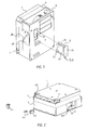
- a coin- and token-dispensing device comprises a housing with three parts: a centre part 4 with a base 5 and, at its periphery, a substantially rectangular frame 6, and on either side of the centre part 4 a first side part 7, which covers a main space of the centre part 4 delimited by the frame 6, and a second side part 9, which in combination with the centre part 4 forms a coin and token holder.
- a coin- and token-dispensing device is in use, it is oriented as shown in Fig. 1.
- the terms vertical and horizontal directions refer to the orientation illustrated in Fig. 1.
- the conveyor member 11 is guided over guide means, such as the strip 14 leading from the base 5, in such a manner that a radius of a bottom section of the loop is preferably smaller than a radius of a top section of the loop.
- a gearwheel 16 engages on an outer side, perpendicular to a main plane of the loop, of the conveyor member 11.
- the gearwheel 16 engages on a transmission wheel 17 which is arranged on the shaft of a motor 18 which is accommodated outside the centre part 4, in a space 19 of the second side part 9.
- the motor 18 is running, the conveyor member 11 is rotated in the direction 21.
- driver members On the inner side of the conveyor member 11, which cannot be seen in Fig. 3, there are driver members, for example those which are known from US-4353794-A. Each driver member is suitable for carrying a coin or token resting on it upwards with the coin or token bearing against the conveyor member 1 in its section which rises obliquely upwards with the links 12 shown.
- Coins or tokens can drop out of the coin and token holder, which is defined by the combination of the centre part 4 and the second side part 19, over an inclined base 23 of the coin or token holder and via an introduction opening 24 in the base 5 of the centre part onto a bottom section of the inner side of the conveyor member 11 or onto coins or tokens which are already located there.
- a vibratory member 26, which is not illustrated in more detail, can assist this conveying of coins or tokens through the introduction opening 24.
- the base 5 of the centre part 4 has an outlet opening, which cannot be seen in the figures but opens out into an outlet space 28 of the second side part 9.
- the outlet space 28 at least partially has an inclined base 29.
- Electrical control means receive the detection signal and power the motor 18 as a function thereof.
- One end of a cable is connected to the control means, and another end of the cable is connected to a connector.
- the coin- and token-dispensing device comprises an insert member 30 which can be displaced, for example slid, into and out of the housing of the device from the outside via an opening 32 in an outer wall of the housing.
- the insert member 30 comprises means for detecting dispensing of coins and tokens by the coin- and token-dispensing device.
- the insert member 30 comprises a carrier 31, which is in particular a printed circuit board (PCB) on which the detection member and control means of the coin- and token-dispensing device can be arranged.
- the carrier 31 is covered by a cover plate 33.
- the cover plate 33 transversely with respect to a main plane thereof, at one end has a wall plate 34 and at the other end has a bridge 35 which, together with the cover plate 33, leaves clear an aperture 36 for coins and tokens to be passed through.
- the wall plate 34 is preferably positioned flush within the boundary of the opening 32.
- cover plate 33 and the wall plate 34 are transparent and to form an integral unit, secured to the carrier 31, with the bridge 35.
- a light reflector (not shown).
- the reflector there are one or more light transmitters and receivers (not shown) on the carrier 31, making it possible to detect the passage of a coin or token through the aperture 36.
- indicators such as LEDs, (not shown) of the control means can be arranged on the carrier 31 next to the wall plate 34, indicating the operation and/or condition and therefore any need to carry out maintenance on the coin- and token-dispensing device when the carrier 31 has been screwed into the housing of the device, and these indicators are visible via the transparent wall plate 36.
- the cable with a connector 42 at one end, can be guided to one end or the other end of the passage 41, with the application of a certain force, via the slot which is left clear by the strip 40.
- Recesses in the first side part 7 and if appropriate in the centre part 4 at the ends of the passage 41 are suitable for the connector 42 to be placed in and then held captively by means of a locking member 44.
- a covering member 45 can be fitted at the other end of the passage 41 from the end having the connector 42.
- the insert member 30 could be displaced via an opening in a different wall of the housing, for example from the top or as a function of the wall of the housing in which the outlet space 28 opens out.
- a displacement of the insert member 30 into and out of the housing comprises a sliding movement, a tilting movement or other movements or combinations of movements.
- an electric circuit arranged on the insert member 30 may be connected, optionally via connectors, to internal electrical means.
- an electric circuit arranged on the insert member 30 to be connected, optionally via connectors, to internal electrical means.
Landscapes
- Physics & Mathematics (AREA)
- General Physics & Mathematics (AREA)
- Control Of Vending Devices And Auxiliary Devices For Vending Devices (AREA)
- Pinball Game Machines (AREA)
- Slot Machines And Peripheral Devices (AREA)
Abstract
Description
Claims (8)
- Coin- and token-dispensing device, comprising a housing inside which there is an endless, belt-like conveyor member (11) with, during use, substantially vertical main planes and provided on the inner side with catch members which are located at a distance from one another, a holder for coins or tokens with an introduction opening (24), which is present above a bottom section of the conveyor member (11), for guiding coins or tokens out of the holder onto the conveyor member (11), drive means (16, 17, 18) for rotational displacement, in a conveying direction (21), of the conveyor member (11) in order to displace coins or tokens upwards on the catch members, an outlet opening, arranged at a rising section of the inner side of the conveyor member (11) for discharging coins or tokens from catch members which are displaced past the outlet opening to outside the device, an electrical detection member arranged at the outlet opening for detecting the discharge of a coin or token and for supplying a corresponding detection signal, and electrical control means connected to the detection member and the drive means for controlling the drive means as a function of the detection signal, characterized by an insert member (30), which comprises a carrier (31) and which can be displaced into and out of the housing via an opening (32) in a wall of the housing, and whereby the detection member is arranged on a carrier (31).
- Coin- and token-dispensing device according to claim 1, characterized in that the insert member (30) can be displaced perpendicular to main planes of the conveyor member (11).
- Coin- and token-dispensing device according to a preceding claim, characterized in that the detection member is an optical detection member.
- Coin- and token-dispensing device according to a preceding claim, characterized in that at least a section of the control means is arranged on the carrier (31).
- Coin- and token-dispensing device according to claim 4, characterized in that the insert member (30) comprises a wall plate (34) which is transparent and which, with the insert member (30) fitted into the housing, covers the opening (32), and in that the control means comprise one or more indicators which are arranged on the insert member (30) in such a manner that they are visible via the wall plate (34).
- Coin- and token-dispensing device according to a preceding claim, characterized in that the control means are connected via a cable to a connector (42), along one side of the housing, over the entire length thereof, there is a passage (41) for laying the cable from the control means in a longitudinal direction of the passage (41) or in the opposite direction, and each end of the passage (41) being suitable for the connector (42) to be placed therein.
- Coin- and token-dispensing device according to claim 6, characterized in that each end of the cable (41) is suitable for a covering member (45) to be placed in.
- Coin- and token-dispensing device according to claim 6 or 7, characterized in that each end of the passage (41) is suitable for placing a locking member (44) in, in order to hold in place another component (42, 45) placed in the end.
Applications Claiming Priority (2)
| Application Number | Priority Date | Filing Date | Title |
|---|---|---|---|
| NL1023677A NL1023677C2 (en) | 2003-06-17 | 2003-06-17 | Coin delivery device. |
| NL1023677 | 2003-06-17 |
Publications (2)
| Publication Number | Publication Date |
|---|---|
| EP1489561A1 true EP1489561A1 (en) | 2004-12-22 |
| EP1489561B1 EP1489561B1 (en) | 2007-08-15 |
Family
ID=33411902
Family Applications (1)
| Application Number | Title | Priority Date | Filing Date |
|---|---|---|---|
| EP04076733A Revoked EP1489561B1 (en) | 2003-06-17 | 2004-06-10 | Coin- and token dispensing device |
Country Status (5)
| Country | Link |
|---|---|
| EP (1) | EP1489561B1 (en) |
| AT (1) | ATE370474T1 (en) |
| DE (1) | DE602004008155T2 (en) |
| ES (1) | ES2291811T3 (en) |
| NL (1) | NL1023677C2 (en) |
Cited By (3)
| Publication number | Priority date | Publication date | Assignee | Title |
|---|---|---|---|---|
| WO2006003212A3 (en) * | 2004-07-07 | 2006-06-22 | Money Controls Ltd | Money item dispensing apparatus |
| WO2009104034A3 (en) * | 2007-04-11 | 2009-10-29 | Paytec S.P.A. | Machine for accepting and distributing coins and/or tokens |
| ITBO20100370A1 (en) * | 2010-06-11 | 2011-12-12 | Alberici S P A | ADAPTER FOR COIN DISPENSER DEVICE |
Citations (2)
| Publication number | Priority date | Publication date | Assignee | Title |
|---|---|---|---|---|
| US4535794A (en) * | 1981-11-20 | 1985-08-20 | Coin Controls Limited | Machine having a coin or token payout mechanism |
| US20020060120A1 (en) * | 2000-11-02 | 2002-05-23 | Proindumar, S.L. | Support for a motion sensor of coins supplied by the hopper of a recreational machine |
-
2003
- 2003-06-17 NL NL1023677A patent/NL1023677C2/en not_active IP Right Cessation
-
2004
- 2004-06-10 AT AT04076733T patent/ATE370474T1/en not_active IP Right Cessation
- 2004-06-10 DE DE602004008155T patent/DE602004008155T2/en not_active Expired - Lifetime
- 2004-06-10 ES ES04076733T patent/ES2291811T3/en not_active Expired - Lifetime
- 2004-06-10 EP EP04076733A patent/EP1489561B1/en not_active Revoked
Patent Citations (2)
| Publication number | Priority date | Publication date | Assignee | Title |
|---|---|---|---|---|
| US4535794A (en) * | 1981-11-20 | 1985-08-20 | Coin Controls Limited | Machine having a coin or token payout mechanism |
| US20020060120A1 (en) * | 2000-11-02 | 2002-05-23 | Proindumar, S.L. | Support for a motion sensor of coins supplied by the hopper of a recreational machine |
Cited By (6)
| Publication number | Priority date | Publication date | Assignee | Title |
|---|---|---|---|---|
| WO2006003212A3 (en) * | 2004-07-07 | 2006-06-22 | Money Controls Ltd | Money item dispensing apparatus |
| US8181765B2 (en) | 2004-07-07 | 2012-05-22 | Money Controls Limited | Money item dispensing apparatus |
| US8844704B2 (en) | 2004-07-07 | 2014-09-30 | Money Controls Limited | Money item dispensing apparatus |
| WO2009104034A3 (en) * | 2007-04-11 | 2009-10-29 | Paytec S.P.A. | Machine for accepting and distributing coins and/or tokens |
| ITBO20100370A1 (en) * | 2010-06-11 | 2011-12-12 | Alberici S P A | ADAPTER FOR COIN DISPENSER DEVICE |
| EP2395484A1 (en) * | 2010-06-11 | 2011-12-14 | Alberici S.p.A. | Adapter for coin dispensing device |
Also Published As
| Publication number | Publication date |
|---|---|
| DE602004008155T2 (en) | 2008-05-08 |
| NL1023677C2 (en) | 2004-12-20 |
| EP1489561B1 (en) | 2007-08-15 |
| DE602004008155D1 (en) | 2007-09-27 |
| ATE370474T1 (en) | 2007-09-15 |
| ES2291811T3 (en) | 2008-03-01 |
Similar Documents
| Publication | Publication Date | Title |
|---|---|---|
| JP2000153038A (en) | Ball game machine | |
| US6761627B2 (en) | Coin dispensing apparatus with removable auxiliary storage unit | |
| EP1489561B1 (en) | Coin- and token dispensing device | |
| JP4909872B2 (en) | Amusement stand | |
| JP4457044B2 (en) | Game machine | |
| EP1530175B1 (en) | Gaming machine | |
| US5377809A (en) | Coin control systems for automatic machines | |
| JP2918203B2 (en) | Ball game machine | |
| JP2000140327A (en) | Ball payout device for pachinko machines | |
| JP2004089506A (en) | Inner frame structure of game machine, winning ball paying out mechanism | |
| GB2260206A (en) | Sheet counting machine | |
| JP7265270B2 (en) | Coin hopper, coin processing equipment | |
| JP2000079225A (en) | Game ball payout device | |
| JP2004105600A (en) | Game machine | |
| JP4140183B2 (en) | Game machine | |
| JP2000126405A (en) | Pachinko machine | |
| JPH0975523A (en) | Collective cover for safe balls in pachinko machines | |
| JP2001046680A (en) | Gaming machine | |
| JP2918217B2 (en) | Ball game machine | |
| JP2000079227A (en) | Game ball sending device | |
| EP1519334A2 (en) | Gaming machine | |
| JP2006039948A (en) | Coin delivery machine | |
| JP2000079224A (en) | Ball game machine | |
| JPH0751169B2 (en) | Pachinko machine | |
| JPH07100256A (en) | Pachinko machine winning ball set cover |
Legal Events
| Date | Code | Title | Description |
|---|---|---|---|
| PUAI | Public reference made under article 153(3) epc to a published international application that has entered the european phase |
Free format text: ORIGINAL CODE: 0009012 |
|
| 17P | Request for examination filed |
Effective date: 20040920 |
|
| AK | Designated contracting states |
Kind code of ref document: A1 Designated state(s): AT BE BG CH CY CZ DE DK EE ES FI FR GB GR HU IE IT LI LU MC NL PL PT RO SE SI SK TR |
|
| AX | Request for extension of the european patent |
Extension state: AL HR LT LV MK |
|
| 17Q | First examination report despatched |
Effective date: 20050401 |
|
| AKX | Designation fees paid |
Designated state(s): AT BE BG CH CY CZ DE DK EE ES FI FR GB GR HU IE IT LI LU MC NL PL PT RO SE SI SK TR |
|
| GRAP | Despatch of communication of intention to grant a patent |
Free format text: ORIGINAL CODE: EPIDOSNIGR1 |
|
| RAP1 | Party data changed (applicant data changed or rights of an application transferred) |
Owner name: SUZO INTERNATIONAL (NL) B.V. |
|
| GRAS | Grant fee paid |
Free format text: ORIGINAL CODE: EPIDOSNIGR3 |
|
| GRAA | (expected) grant |
Free format text: ORIGINAL CODE: 0009210 |
|
| AK | Designated contracting states |
Kind code of ref document: B1 Designated state(s): AT BE BG CH CY CZ DE DK EE ES FI FR GB GR HU IE IT LI LU MC NL PL PT RO SE SI SK TR |
|
| REG | Reference to a national code |
Ref country code: GB Ref legal event code: FG4D |
|
| REG | Reference to a national code |
Ref country code: CH Ref legal event code: EP |
|
| REG | Reference to a national code |
Ref country code: IE Ref legal event code: FG4D |
|
| REF | Corresponds to: |
Ref document number: 602004008155 Country of ref document: DE Date of ref document: 20070927 Kind code of ref document: P |
|
| PG25 | Lapsed in a contracting state [announced via postgrant information from national office to epo] |
Ref country code: FI Free format text: LAPSE BECAUSE OF FAILURE TO SUBMIT A TRANSLATION OF THE DESCRIPTION OR TO PAY THE FEE WITHIN THE PRESCRIBED TIME-LIMIT Effective date: 20070815 Ref country code: BG Free format text: LAPSE BECAUSE OF FAILURE TO SUBMIT A TRANSLATION OF THE DESCRIPTION OR TO PAY THE FEE WITHIN THE PRESCRIBED TIME-LIMIT Effective date: 20071115 |
|
| PG25 | Lapsed in a contracting state [announced via postgrant information from national office to epo] |
Ref country code: CH Free format text: LAPSE BECAUSE OF FAILURE TO SUBMIT A TRANSLATION OF THE DESCRIPTION OR TO PAY THE FEE WITHIN THE PRESCRIBED TIME-LIMIT Effective date: 20070815 Ref country code: LI Free format text: LAPSE BECAUSE OF FAILURE TO SUBMIT A TRANSLATION OF THE DESCRIPTION OR TO PAY THE FEE WITHIN THE PRESCRIBED TIME-LIMIT Effective date: 20070815 Ref country code: PL Free format text: LAPSE BECAUSE OF FAILURE TO SUBMIT A TRANSLATION OF THE DESCRIPTION OR TO PAY THE FEE WITHIN THE PRESCRIBED TIME-LIMIT Effective date: 20070815 |
|
| REG | Reference to a national code |
Ref country code: CH Ref legal event code: PL |
|
| REG | Reference to a national code |
Ref country code: ES Ref legal event code: FG2A Ref document number: 2291811 Country of ref document: ES Kind code of ref document: T3 |
|
| PG25 | Lapsed in a contracting state [announced via postgrant information from national office to epo] |
Ref country code: BE Free format text: LAPSE BECAUSE OF FAILURE TO SUBMIT A TRANSLATION OF THE DESCRIPTION OR TO PAY THE FEE WITHIN THE PRESCRIBED TIME-LIMIT Effective date: 20070815 |
|
| EN | Fr: translation not filed | ||
| PG25 | Lapsed in a contracting state [announced via postgrant information from national office to epo] |
Ref country code: DK Free format text: LAPSE BECAUSE OF FAILURE TO SUBMIT A TRANSLATION OF THE DESCRIPTION OR TO PAY THE FEE WITHIN THE PRESCRIBED TIME-LIMIT Effective date: 20070815 Ref country code: GR Free format text: LAPSE BECAUSE OF FAILURE TO SUBMIT A TRANSLATION OF THE DESCRIPTION OR TO PAY THE FEE WITHIN THE PRESCRIBED TIME-LIMIT Effective date: 20071116 |
|
| PLBI | Opposition filed |
Free format text: ORIGINAL CODE: 0009260 |
|
| PG25 | Lapsed in a contracting state [announced via postgrant information from national office to epo] |
Ref country code: CZ Free format text: LAPSE BECAUSE OF FAILURE TO SUBMIT A TRANSLATION OF THE DESCRIPTION OR TO PAY THE FEE WITHIN THE PRESCRIBED TIME-LIMIT Effective date: 20070815 Ref country code: PT Free format text: LAPSE BECAUSE OF FAILURE TO SUBMIT A TRANSLATION OF THE DESCRIPTION OR TO PAY THE FEE WITHIN THE PRESCRIBED TIME-LIMIT Effective date: 20080115 Ref country code: SK Free format text: LAPSE BECAUSE OF FAILURE TO SUBMIT A TRANSLATION OF THE DESCRIPTION OR TO PAY THE FEE WITHIN THE PRESCRIBED TIME-LIMIT Effective date: 20070815 |
|
| 26 | Opposition filed |
Opponent name: HOPPER S.R.L. Effective date: 20080506 |
|
| PG25 | Lapsed in a contracting state [announced via postgrant information from national office to epo] |
Ref country code: SE Free format text: LAPSE BECAUSE OF FAILURE TO SUBMIT A TRANSLATION OF THE DESCRIPTION OR TO PAY THE FEE WITHIN THE PRESCRIBED TIME-LIMIT Effective date: 20071115 Ref country code: RO Free format text: LAPSE BECAUSE OF FAILURE TO SUBMIT A TRANSLATION OF THE DESCRIPTION OR TO PAY THE FEE WITHIN THE PRESCRIBED TIME-LIMIT Effective date: 20070815 |
|
| NLR1 | Nl: opposition has been filed with the epo |
Opponent name: HOPPER S.R.L. |
|
| PLAX | Notice of opposition and request to file observation + time limit sent |
Free format text: ORIGINAL CODE: EPIDOSNOBS2 |
|
| PLAF | Information modified related to communication of a notice of opposition and request to file observations + time limit |
Free format text: ORIGINAL CODE: EPIDOSCOBS2 |
|
| PG25 | Lapsed in a contracting state [announced via postgrant information from national office to epo] |
Ref country code: MC Free format text: LAPSE BECAUSE OF NON-PAYMENT OF DUE FEES Effective date: 20080630 |
|
| PLBB | Reply of patent proprietor to notice(s) of opposition received |
Free format text: ORIGINAL CODE: EPIDOSNOBS3 |
|
| PG25 | Lapsed in a contracting state [announced via postgrant information from national office to epo] |
Ref country code: IE Free format text: LAPSE BECAUSE OF NON-PAYMENT OF DUE FEES Effective date: 20080610 Ref country code: EE Free format text: LAPSE BECAUSE OF FAILURE TO SUBMIT A TRANSLATION OF THE DESCRIPTION OR TO PAY THE FEE WITHIN THE PRESCRIBED TIME-LIMIT Effective date: 20070815 |
|
| PLAB | Opposition data, opponent's data or that of the opponent's representative modified |
Free format text: ORIGINAL CODE: 0009299OPPO |
|
| PG25 | Lapsed in a contracting state [announced via postgrant information from national office to epo] |
Ref country code: SI Free format text: LAPSE BECAUSE OF FAILURE TO SUBMIT A TRANSLATION OF THE DESCRIPTION OR TO PAY THE FEE WITHIN THE PRESCRIBED TIME-LIMIT Effective date: 20070815 |
|
| PG25 | Lapsed in a contracting state [announced via postgrant information from national office to epo] |
Ref country code: CY Free format text: LAPSE BECAUSE OF FAILURE TO SUBMIT A TRANSLATION OF THE DESCRIPTION OR TO PAY THE FEE WITHIN THE PRESCRIBED TIME-LIMIT Effective date: 20070815 |
|
| PGFP | Annual fee paid to national office [announced via postgrant information from national office to epo] |
Ref country code: AT Payment date: 20090625 Year of fee payment: 6 |
|
| PG25 | Lapsed in a contracting state [announced via postgrant information from national office to epo] |
Ref country code: HU Free format text: LAPSE BECAUSE OF FAILURE TO SUBMIT A TRANSLATION OF THE DESCRIPTION OR TO PAY THE FEE WITHIN THE PRESCRIBED TIME-LIMIT Effective date: 20080216 Ref country code: LU Free format text: LAPSE BECAUSE OF NON-PAYMENT OF DUE FEES Effective date: 20080610 |
|
| PG25 | Lapsed in a contracting state [announced via postgrant information from national office to epo] |
Ref country code: TR Free format text: LAPSE BECAUSE OF FAILURE TO SUBMIT A TRANSLATION OF THE DESCRIPTION OR TO PAY THE FEE WITHIN THE PRESCRIBED TIME-LIMIT Effective date: 20070815 |
|
| PG25 | Lapsed in a contracting state [announced via postgrant information from national office to epo] |
Ref country code: AT Free format text: LAPSE BECAUSE OF NON-PAYMENT OF DUE FEES Effective date: 20100610 |
|
| REG | Reference to a national code |
Ref country code: NL Ref legal event code: PLED Effective date: 20120822 |
|
| PG25 | Lapsed in a contracting state [announced via postgrant information from national office to epo] |
Ref country code: FR Free format text: LAPSE BECAUSE OF FAILURE TO SUBMIT A TRANSLATION OF THE DESCRIPTION OR TO PAY THE FEE WITHIN THE PRESCRIBED TIME-LIMIT Effective date: 20080411 |
|
| PGFP | Annual fee paid to national office [announced via postgrant information from national office to epo] |
Ref country code: DE Payment date: 20130624 Year of fee payment: 10 Ref country code: GB Payment date: 20130612 Year of fee payment: 10 |
|
| PGFP | Annual fee paid to national office [announced via postgrant information from national office to epo] |
Ref country code: IT Payment date: 20130625 Year of fee payment: 10 |
|
| PLAB | Opposition data, opponent's data or that of the opponent's representative modified |
Free format text: ORIGINAL CODE: 0009299OPPO |
|
| R26 | Opposition filed (corrected) |
Opponent name: HOPPER S.R.L. Effective date: 20080506 |
|
| PGFP | Annual fee paid to national office [announced via postgrant information from national office to epo] |
Ref country code: NL Payment date: 20130627 Year of fee payment: 10 Ref country code: ES Payment date: 20130624 Year of fee payment: 10 |
|
| RDAF | Communication despatched that patent is revoked |
Free format text: ORIGINAL CODE: EPIDOSNREV1 |
|
| REG | Reference to a national code |
Ref country code: DE Ref legal event code: R103 Ref document number: 602004008155 Country of ref document: DE Ref country code: DE Ref legal event code: R064 Ref document number: 602004008155 Country of ref document: DE |
|
| RDAG | Patent revoked |
Free format text: ORIGINAL CODE: 0009271 |
|
| STAA | Information on the status of an ep patent application or granted ep patent |
Free format text: STATUS: PATENT REVOKED |
|
| 27W | Patent revoked |
Effective date: 20140214 |
|
| GBPR | Gb: patent revoked under art. 102 of the ep convention designating the uk as contracting state |
Effective date: 20140214 |
|
| REG | Reference to a national code |
Ref country code: DE Ref legal event code: R107 Ref document number: 602004008155 Country of ref document: DE Effective date: 20140724 |
|
| REG | Reference to a national code |
Ref country code: AT Ref legal event code: MA03 Ref document number: 370474 Country of ref document: AT Kind code of ref document: T Effective date: 20140214 |